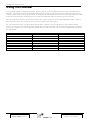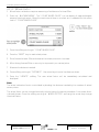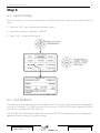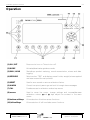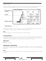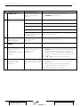
1
Canlink 3500 VRC/MON
Operator’s
Manual
Version 5.00.26
Simplicity Airseeder
VRC / Monitor
1
3500 VRC Operator’s Manual
System Overview
The canlink 3500 is a flexible instrument designed to fulfil a variety of monitoring, guidance and
control operations using GPS equipment.
The canlink VRC / Monitor cab module is setup to run variable rate control of the airseeder
through a processor (pod), mounted on the airseeder that manages up to 4 bin metering units (1
metering unit for Monitor) and monitors essential airseeder functions.
When calibrating the bins, seed and fertiliser calibration factors can be stored for up to 24 product
names, saving considerable time in the field when leaving one crop and entering another. Product
names can be edited to reflect specific seed varieties or fertiliser names.
Trip names can be edited to reflect true field names or numbers. Records of actual product areas
and weights are automatically maintained for each trip as well as overall totals of each product
applied.
Product rates set for each bin, can be pre-programmed for up to 100 trips (fields) then simply
recalled by the operator when required. Bins can be individually switched ‘off’ or ‘on’ from the cab
and application rates can be manually increased or decreased in predefined steps.
Selected rates are automatically governed by ground speed and machine operation can be stopped
at any time by pressing the “RUN/HOLD” key or by lifting the implement, if an optional ram
position sensor is installed.
The canlink provides monitoring of twin fan speed, dual air pressure, bin levels and product
metering shafts with selectable alarm points on critical functions and a control lockout if fan rpm is
too slow.
After initial installation of tractor components, refer to the airseeder manufacturer’s instructions for
correct configuration of bin controls, sensors, machine parameters and recommended alarm points.
See Steps 2 to 5 of the Setup section for instructions. Follow the procedure for product calibration
in Step 3 after initial setup is completed.
All system configuration and calibration factors including product and trip names are permanently
stored in the canlink for reuse at any time. It is recommended to recheck calibration factors before
each sowing season to account for variations in product densities.
A new feature now available on the canlink 3500 platform is parallel guidance. In guidance mode,
activated by pressing the “MODE” key a virtual road, steering prompts, row counter, heading and
cross track error are displayed. A boundary and headland function enables field area to be
calculated while notifying the operator when headland areas have been entered.
With GPS/DGPS connected to the canlink, the data card slot allows application rates to be logged,
for comparison with yield maps. With DGPS/GPS and an application map using a data card, the
canlink will automatically apply the rates assigned in the map.
Future product developments can be uploaded via the data card slot.
V5.00.26
October 2006 Revision M
Part No. : AM-3500V/M/SIMV5
Updated : 12/10/2006
2
3500 VRC Operator’s Manual
Contents
Using this manual......................................................................................................................................4
3500VRC System Diagram .......................................................................................................................5
3500VRC System Overview .....................................................................................................................6
BATTERY CONNECTION............................................................................................................................6
Step 1............................................................................................................................................................7
1.1 - Units Selection....................................................................................................................................7
1.2 – Pod Detection ....................................................................................................................................8
Step 2............................................................................................................................................................9
2 - Drive Setup............................................................................................................................................9
Step 3......................................................................................................................................................... 15
3.1 - Product Calibration...........................................................................................................................15
3.2 – Target Rate and Step Size ................................................................................................................23
3.3 - Fine Tuning Calibration Factors.........................................................................................................24
3.4 - Reusing Product Calibration Factors..................................................................................................26
Step 4......................................................................................................................................................... 27
4.1 - Machine Calibration .........................................................................................................................27
Step 5......................................................................................................................................................... 29
5.1 - Alarms Setup ....................................................................................................................................29
5.3 - Air Pressure Alarm (where fitted)......................................................................................................32
5.4 - Drive Ratio/Shaft Alarms (where fitted).............................................................................................33
5.5 - Bin Level Alarm.................................................................................................................................35
5.6 - Depth Alarm (where fitted)...............................................................................................................36
5.7 - Aux Alarm (where fitted) ..................................................................................................................37
5.8 – Pump 2 Speed (Liquid Tank Only).....................................................................................................38
5.9 – Bin Liquid Pressure Alarm (where fitted)...........................................................................................39
Step 6......................................................................................................................................................... 40
6.1 - Options Setup...................................................................................................................................40
6.2 - Pod Detection...................................................................................................................................40
6.3 – Run/Hold Input.................................................................................................................................41
6.4 - Units .................................................................................................................................................43
6.5 – Prime (Liquid Tank Only) ..................................................................................................................43
6.6 - Two Tenths of a Hectare (Liquid Tank Only)......................................................................................43
Step 7......................................................................................................................................................... 44
7.1 - Display Setup....................................................................................................................................44
7.2 - Contrast............................................................................................................................................44
7.3 - Backlighting......................................................................................................................................45
7.4 - Display Invert....................................................................................................................................45
7.5 - Lightbar Brightness...........................................................................................................................45
Step 8......................................................................................................................................................... 46
8.1 - Time, Date and GPS Setup................................................................................................................46
8.2 - Time .................................................................................................................................................46
8.3 - GPS...................................................................................................................................................47
Step 9......................................................................................................................................................... 48
9.1 - Data Card & Logging Interval............................................................................................................48
9.2 - Logging Interval................................................................................................................................49
9.3 – Upload Software ..............................................................................................................................50
9.4 – Application Maps .............................................................................................................................51
V5.00.26
October 2006 Revision M
Part No. : AM-3500V/M/SIMV5
Updated : 12/10/2006
3
3500 VRC Operator’s Manual
Step 10 ...................................................................................................................................................... 53
10.1 - Guidance Setup..............................................................................................................................53
10.2 - Guide Sensitivity .............................................................................................................................53
10.3 - GPS to Implement...........................................................................................................................54
10.4 - Headland Hold................................................................................................................................54
10.5 - Nudge.............................................................................................................................................54
Step 11 ...................................................................................................................................................... 55
11. 1 Flexi Steer (Autosteer)......................................................................................................................55
11.2 Flexi Steer calibration ........................................................................................................................57
11.3 Gyro Quick Calibration......................................................................................................................58
Operation ................................................................................................................................................. 59
Run/Hold Operation ..................................................................................................................................60
Alarm Key .................................................................................................................................................61
Cal Key......................................................................................................................................................61
Mode Key .................................................................................................................................................62
Main Screen ............................................................................................................................................. 63
Main Screen Features................................................................................................................................63
Bin Controls ..............................................................................................................................................71
Auto Control.............................................................................................................................................76
Records Screen ........................................................................................................................................ 81
Guidance................................................................................................................................................... 88
Boundary ..................................................................................................................................................88
Parallel Swath Guidance............................................................................................................................92
Flag.........................................................................................................................................................101
Nudge .....................................................................................................................................................103
Operating Flexi Steer...............................................................................................................................103
Data Card Operation ...........................................................................................................................104
Insert Data Card......................................................................................................................................104
Remove Data Card..................................................................................................................................104
Erase Data Card ......................................................................................................................................106
How the canlink Logs Data .....................................................................................................................107
Upload Software .....................................................................................................................................108
Data Card Formatting .............................................................................................................................109
Diagnostics.............................................................................................................................................111
Troubleshooting ...................................................................................................................................112
Notes .......................................................................................................................................................120
V5.00.26
October 2006 Revision M
Part No. : AM-3500V/M/SIMV5
Updated : 12/10/2006
4
3500 VRC Operator’s Manual
Using this manual
The following manual is a detailed document, which covers all, drives and applications used by the 3500VRC/MON
software. This manual covers all airseeder/spreader/combine drill types that are sold with the 3500VRC/MON. On the
bottom of each page you will find the version of software that was released at the time the manual was printed. Please
quote this software version number when you consult your Farmscan dealer or Farmscan service personnel.
Each 3500VRC/MON monitor has a communications pod, which is found on the airseeder/spreader/combine. This too
has a software version and can be found on the 3500 monitor (see SETUP menu).
For your convenience there is a table below that has been created for you to keep records of your latest software
version. Like any electronic equipment the 3500VRC/MON software will have new features and improvements added in
due course. So when your 3500 is upgraded, please send the manual in with it and our service department will update
the table below.
Version of Software (Monitor)
V5.00.26
V5.00.26
October 2006 Revision M
Version of Software (Pod)
V5.00.26
Date of Release/Upgrade
October 2006
Part No. : AM-3500V/M/SIMV5
Updated : 12/10/2006
5
3500 VRC Operator’s Manual
3500VRC System Diagram
V5.00.26
October 2006 Revision M
Part No. : AM-3500V/M/SIMV5
Updated : 12/10/2006
6
3500 VRC Operator’s Manual
3500VRC System Overview
The 3500VRC uses the A-3505/HC pod to control and receive information from sensors and motors. It is a four channel
controller with two other outputs for on/off control.
Each of the four channels can control a DC Motor, Hydraulic motor, linear actuator or liquid ball valve each. The two
additional outputs can control master valves used in liquid tanks.
BATTERY CONNECTION
Do not connect battery power until installation is complete.
The POWER CABLE must be connected DIRECT to 12 volt DC vehicle battery terminals.
DO NOT connect monitor to auxiliary power point on tractor or join monitor power cable together
with Clutch Power Cable except at Battery Terminals.
USE cable ties supplied to secure power cable away from risk of damage.
Connection to battery terminals must be clean and tight.
WARNING -Disconnect Monitors from battery connection if arc welding on machinery.
TYPICAL BATTERY
RED
BLACK
RED
BLACK
RED
BLACK
POS 24V
POS
POS
NEG
POS 12V
NEG
NEG
POS
NEG
CONNECTION NEG
DETAIL
ONE 12 VOLT BATTERY
12V Tractors
V5.00.26
October 2006 Revision M
VEHICLE
GROUND
TWO 6 VOLT BATTERIES
TWO 12 VOLT BATTERIES
24V Tractors
Part No. : AM-3500V/M/SIMV5
Updated : 12/10/2006
7
3500 VRC Operator’s Manual
Step 1
1.1 - Units Selection
To display quantities in US imperial units follow the steps below. Otherwise skip to “1.2 – Pod
Selection” on the next page.
Note
Default setting is units displayed in metric.
1.1.1 - Select US imperial
1. Press “CAL” key. The calibration menu appears.
2. Highlight “OPTIONS”.
3. Press the softkey pointing at “UNITS”.
4. Use the up and down arrow keys to toggle between “METRIC” and “US”.
V5.00.26
October 2006 Revision M
Part No. : AM-3500V/M/SIMV5
Updated : 12/10/2006
8
3500 VRC Operator’s Manual
1.2 – Pod Detection
The canlink 3500 controller will work with either the 3500 or 3000 control pod versions. Whereas,
the canlink 3000 will only work with the 3000 control pod.
The control pod version is automatically detected with version V5.00.26 and onwards in the 3500.
It will display the detected Pod on the top of the options screen (see Step 6).
V5.00.26
October 2006 Revision M
Part No. : AM-3500V/M/SIMV5
Updated : 12/10/2006
9
3500 VRC Operator’s Manual
Step 2
2 - Drive Setup
Drives for each bin must be selected and calibrated (setup) before operation.
2.1 – Drives Available
Bins 1, 2 & 3
DC MOTOR
GEAR BOX
Bin 4
DC MOTOR
GEAR BOX
HYD PROP 2
HYD PROP 2
Output 5 & 6
HYD PROP/XPRO HYD PROP/XPRO
HYD MFC
HYD MFC
HYD DANFOSS
HYD DANFOSS
HYD DANFOSS L
HYD DANFOSS L
LIQUID
MONITOR
LIQUID
MONITOR
CLUTCHSOL
CLUTCHSOL
CLUTCHLIN
Section Valve 2 wire
Section Valve 3 wire
Description
12 volt DC motor
Linear actuator over gear box (ground
drive)
Hydraulic proportional valve with
dither
Hydraulic proportional valve
Motorized flow control valve
Hydraulic PVG32 Danfoss valve
(proportional valve)
Hydraulic PVG32 Danfoss valve
(proportional valve) operating a pump
Control valve and flow sensor
Solenoid activated clutch for bin –
monitors only – no control.
Solenoid activated clutch on ‘run/hold’
Linear actuated clutch on ‘run/hold’
Motorised 2 wire section valves
Motorised 3 wire or solenoid section
valves
Note
An extra control option is available for bin 4: “CLUTCHLIN” (linear actuator clutch).
2.2 – Setting Up Drives
To calibrate a bin drive, the bin must be enabled and a drive selected. Follow the procedures below
“2.2.1 - Enable Bin Drive” and “2.2.2 - Select Bin Drive” for each bin.
V5.00.26
October 2006 Revision M
Part No. : AM-3500V/M/SIMV5
Updated : 12/10/2006
10
3500 VRC Operator’s Manual
2.2.1 - Enable Bin Drive
1. Press “CAL” key, calibration menu appears.
2. Highlight “SETUP” and press “CAL”. The “CONTROL SETUP MENU” appears.
Press & hold for
3 seconds to
enable Bin 1
CONTROL SETUP MENU
POD
BIN 1
ENABLED
BIN 2
DISABLED
BIN 3
DISABLED
BIN 4
DISABLED
<PREV
NEXT>
SELECT
RATES
BACK
EXIT
3. Press and hold the softkey pointing at the required bin for 3 seconds.
4. Bin will change from “DISABLED” to “ENABLED”.
Linear Actuator over Gearbox
No setup screen is displayed. The gearbox drive is immediately calibrated upon selection.
Output 5 & 6
These two outputs are only selected if “LIQUID” is being used. Output 5 & 6 have the ability to run
two wire and three wire master on/off valves for liquid only. They must be associated with bin 1, 2,
3 or 4. There can only be one master on/off valve per bin.
On a Simplicity Liquid setup OUTPUT 5 must be enabled as a 2 WIRE VALVE and associated to BIN
4.
This is shown below –
V5.00.26
October 2006 Revision M
Part No. : AM-3500V/M/SIMV5
Updated : 12/10/2006
11
3500 VRC Operator’s Manual
Valve 2 wire – master on/off valve is two wire configuration.
Output 5 must be associated to the liquid bin 4. This is done in the following screens –
The above shows OUTPUT 5 – VALVE 2 WIRE set up as the master on/off valve for Bin 4. Therefore
when Bin 4 is turned off or placed on hold OUTPUT 5 will trigger the master valve in the liquid
manifold.
V5.00.26
October 2006 Revision M
Part No. : AM-3500V/M/SIMV5
Updated : 12/10/2006
12
3500 VRC Operator’s Manual
Liquid
Liquid control is available on all four bins. On a Simplicity liquid bin it is set up on bin 4 however the
3500 software will allow it to work on four bins.
Note: Prior to selecting liquid, if a master valve is being used with the liquid then this
must be selected. See OUTPUT 5 & 6.
1. Check “BIN # LIQUID” is displayed. See below.
2. Select Control Type CTRL to “BYPASS” see “Bypass and Direct Control Explained”.
3. Select Control Valve Hold Status HOLD to “STOP” see “Bypass and Direct Control Explained”.
4. Press the bottom “START” softkey.
5. Press the green button on the pod.
6. The control valve (and Master On/Off Valve if fitted) will open then close again after five
seconds.
7. Press the “END” softkey. A “MAX” pulses per minute factor will be returned.
8. Repeat steps 4 & 5, if the system was not primed initially.
9. For liquid control, initially set the SPD and STEP values to 60 and 1 respectively.
10. Press “BACK” softkey. Check “SETUP OK” is displayed under the drive to confirm it has been
set up correctly.
NOTE: 3500 will return MAX PPM. MAX PPM = P/Lt (of flow meter) x Lt/Min (flow rate).
(Max of 10000PPM for 3500 = higher results will require a signal divider).
V5.00.26
October 2006 Revision M
Part No. : AM-3500V/M/SIMV5
Updated : 12/10/2006
13
3500 VRC Operator’s Manual
Bypass and Direct Control Explained
Pictured below is an example of Bypass control and Direct Control (not applicable to Simplicity
airseeder). Please consult your airseeder manufacturer if you are unsure of which control is being
used.
BYPASS CONTROL
This type of control requires a Master On/Off Valve setup on OUTPUT 5. This type of control
regulates the flow back to the tank, which in turn controls the amount of fluid output to the
airseeder bar.
The user has a choice on how the Control Valve positions itself during the Hold period – Open (max
available pressure to implement), Close (max flow back to tank) and Stop (control valve remains in
control position when on hold).
DIRECT CONTROL (not applicable to Simplicity Airseeder)
This type of control does not require a Master On/Off Valve setup on either OUTPUT 5 or 6. This
type of control regulates the flow through the flow meter (and section valve if fitted) and out to
the airseeder bar.
If a Master On/Off valve has been fitted the user has a choice on how the Control Valve positions
itself during the Hold period - Open (max available pressure to implement), Close (max flow back to
tank) and Stop (control valve remains in control position when on hold).
V5.00.26
October 2006 Revision M
Part No. : AM-3500V/M/SIMV5
Updated : 12/10/2006
14
3500 VRC Operator’s Manual
Monitor
No setup screen is displayed. The monitor reads rate from feedback wheel and displays rate of
ground drive machines only.
V5.00.26
October 2006 Revision M
Part No. : AM-3500V/M/SIMV5
Updated : 12/10/2006
15
3500 VRC Operator’s Manual
Step 3
3.1 - Product Calibration
Before seeding, product calibrations must be created. Product calibrations are the “PULSES/KG” or
“PULSES/L” values seen in the rates screen.
Each product calibration factor is bin and product specific. Product calibration factors are calculated
by dividing the number of test pulses by the test weight.
Follow the instructions 3.1.1, 3.1.2, 3.1.3 and 3.2 for all products.
3.1.1 - Before Calibrating
1. Check bins contain actual product to be applied.
2. The airseeder must be stationary.
3. Current trip records must be reset. See below.
Reset Trip
1. Press “RECORDS” key. Records for the current trip will appear.
2. Press “RESET” key twice to clear all trip records.
V5.00.26
October 2006 Revision M
Part No. : AM-3500V/M/SIMV5
Updated : 12/10/2006
16
3500 VRC Operator’s Manual
3.1.2 - Select Bin & Product
1. Press “CAL”. Calibration menu appears.
2. Highlight “RATES” and press “CAL”. The “TRP001 RATES” menu appears.
Note
If trip 2 or any other trip is active, the “TRP002 RATES” or other menu will appear.
3. Press softkey pointing at bin number. Use up and down arrow keys to select bin number.
4. Press softkey pointing at “SELECT PROD”. The “PRODUCT SELECTION MENU” screen appears.
Note
If records for the current trip have not been cleared, a message prompting you to clear the
current trip will be displayed. Follow the steps below to reset trip records.
Reset Trip Records
1. Press “RECORDS” key.
2. Press the “RESET” key twice to clear all records.
3. Press the “RATES” softkey to return to the rates menu.
V5.00.26
October 2006 Revision M
Part No. : AM-3500V/M/SIMV5
Updated : 12/10/2006
17
3500 VRC Operator’s Manual
5. Press the bottom “<PREV” or “NEXT>” softkeys to display the product to select.
6. Press the left hand softkey pointing at the product, until it has the >> arrow heads next to it.
7. Press the bottom “SELECT” softkey.
8. The rates screen will be displayed with the selected product displayed.
Note
See section “Changing Product Names” in the Operation section of the manual to change product
names and set the product type as either liquid or solid.
V5.00.26
October 2006 Revision M
Part No. : AM-3500V/M/SIMV5
Updated : 12/10/2006
18
3500 VRC Operator’s Manual
3.1.3 - Calibrate Bin & Product
1. Press softkey pointing at “CALIB PRODUCT”. The “PRODUCT CALIBRATION” screen appears.
2. Follow the drive specific instructions on the following pages to calibrate product.
V5.00.26
October 2006 Revision M
Part No. : AM-3500V/M/SIMV5
Updated : 12/10/2006
19
3500 VRC Operator’s Manual
Linear Actuator Over Variable Gearbox
1. Check ”PRODUCT CALIBRATION” screen is displayed. See below.
2. Press bottom “READY” softkey.
3. Press green button on the pod to move the gearbox actuator in one direction. Release and
press the green button again to move the gearbox actuator in the opposite direction.
4. Adjust the gearbox actuator to an approximate normal working position on the calibration dial
for the intended rate as suggested by the airseeder manufacturer.
5. Be ready to catch the product test batch from the metering system.
6. Disengage clutch. Turn the metering system manually to deliver a sizeable calibration sample as
recommended by the airseeder manufacturer. Accurately weigh the product.
7. Press the softkey pointing at “TEST WEIGHT”. Use the arrow keys to enter the weighed
amount.
8. Press the bottom “UPDATE” softkey. The “PULSE/KG” factor for that product will be
automatically calculated.
V5.00.26
October 2006 Revision M
Part No. : AM-3500V/M/SIMV5
Updated : 12/10/2006
20
3500 VRC Operator’s Manual
Liquid
1. Check “PRODUCT CALIBRATION” screen is displayed. See below.
1. Press the softkey pointing at “CAL SPEED”. Use the arrow keys to enter the airseeder
manufacturer’s recommended metering speed for the product being calibrated.
1
5
10
=
=
=
10%
50%
100%
Slowest Speed
Half Speed (Use if unknown)
Maximum Speed
PRODUCT CALIBRATION
BIN
1
0.00
PULSE/LT
Press to highlight
“CAL SPEED”
CAL SPEED
Press to highlight
“TEST PULSES”
value
TEST PULSES
600
Press to highlight
“TEST WEIGHT”
value
TEST WEIGHT
0.00LT
4
CAL
SETPRV
Press to
SETPRV
FLUSH
READY
Press to
FLUSH
Press to start
metering
product for
calibration
UPDATE
BACK
Use arrow keys to
enter: cal speed,
test pulse and
test weight
values.
EXIT
Press to
calculate
“PULSE/KG”
factor
3. Press the softkey pointing at “TEST PULSES”. Use the arrow keys to enter the recommended
number of pulses to obtain a sizeable quantity of product for measuring.
Example “TEST PULSES 600”.
4. Press the bottom “READY” softkey.
5. Be ready at the nozzles to catch product.
6. Press green button on the pod to prime flow control valve, then press red button to stop flow.
Empty bucket and reposition under nozzles.
7. Press green button to start product calibration run (red button may be used to stop and reset
the batch in case of a false start).
8. The flow control valve will stop after completing the test pulse quantity. If the original batch is
too small, repeat step 7 after completion of the first batch to double the quantity.
Note
The displayed “TEST PULSES” count may be slightly higher than the original set amount. Due to
normal motor overrun after reaching the test pulse quantity.
V5.00.26
October 2006 Revision M
Part No. : AM-3500V/M/SIMV5
Updated : 12/10/2006
21
3500 VRC Operator’s Manual
9. Accurately measure volume of product caught.
10. Press the softkey pointing at “TEST VOL”. Use the arrow keys to enter the volume of product
caught.
11. Press the bottom “UPDATE” softkey. A new “PULSE/L” factor will be calculated.
See section 3.3 Fine Tuning Calibration Factors.
SET PRESSURE RELIEF VALVE
Set Pressure Relief Valve. This feature allows the user to set the manual pressure relief valve by
allowing max pressure into the manifold. It achieves this by doing the following –
Bypass Control – Closing the bypass back to tank. Master On/Off Valve remains closed.
?? By pressing the “SETPRV” key the bypass back to tank will cease and the Master On/Off
Valve will remain closed. Once the operator has set the PRV the operator must press the
“SETPRV” button again to complete the procedure to take it out of the SETPRV mode.
Warning: This feature will dead-end the pump if the pressure relief valve has
not been adjusted to max bypass prior to the test.
FLUSH
Flush allows the user to allow max flow through the implement. It also allows the user to set the
maximum pressure on the implement. It achieves this by doing the following –
Bypass Control – Closing the bypass back to tank. Section Valve opens completely.
?? By pressing the “FLUSH” key the bypass to tank will cease and the Master On/Off valve will
open. Once the flush has been completed the operator must press the “FLUSH” button
again to stop open the control valve back to tank and the master on/off valve will close
completing the procedure.
Note: Your Simplicity airseeder also comes with a switch, which allows you to flush the system from
the manifold. This switch opens the Master On/Off valve and closes the DUMP valve
simultaneously. This overrides the flush feature in the “CALIB PROD” screen.
Warning: This feature will allow max flow to the implement. It is
recommended the manual pressure relief valve must be set prior to doing a
flush.
V5.00.26
October 2006 Revision M
Part No. : AM-3500V/M/SIMV5
Updated : 12/10/2006
22
3500 VRC Operator’s Manual
Monitor
1. Check “PRODUCT CALIBRATION” screen is displayed. See below.
2. Press the bottom “READY” softkey.
3. Be ready at the airseeder metering unit to catch product.
4. Press green button on the pod to engage the clutch of that particular bin (if fitted) and turn
the crank handle to turn the drive.
5. The metering unit will commence to turn and the 3500 will count “TEST PULSES”. Stop
turning after a reasonable size sample is metered.
6. Accurately weigh the product.
7. Press the softkey pointing at “TEST WEIGHT”. Use the arrow keys to enter the weight of
product caught.
8. Press the bottom “UPDATE” softkey. A new “PULSE/KG” factor will be calculated.
9. If the metering system was not initially primed then the above procedure will need to be
done again.
V5.00.26
October 2006 Revision M
Part No. : AM-3500V/M/SIMV5
Updated : 12/10/2006
23
3500 VRC Operator’s Manual
3.2 – Target Rate and Step Size
The target rate and step size for each bin is set in the rates screen. Follow the instructions below.
The target rate is the rate in kg/ha that the bin once turned on will automatically control to. This
rate can be increased/decreased in the main screen using the up and down arrows keys. The
amount by which the target rate is increased/decreased is the step size value and is set in the rates
screen.
3.2.1 - Set Target Rate
1. In the rate screen shown above, press the softkey pointing at “RATE”.
2. Use the arrow keys to enter the rate.
3.2.2 - Set Step Size
1. Press the softkey pointing at “STEPS” until the right most digit of the step value is highlighted.
2. Use the arrow keys to enter the step size value.
V5.00.26
October 2006 Revision M
Part No. : AM-3500V/M/SIMV5
Updated : 12/10/2006
24
3500 VRC Operator’s Manual
3.3 - Fine Tuning Calibration Factors
Calibration factors can be fine tuned in two ways. One - after metering a known quantity and
applying an adjustment formula. Two - by using the two tenths of a hectare test.
The two tenths of a hectare test runs the selected drive for 2/10th of a hectare while stationery.
Product can be caught and weighed to check bin calibration factors are correct.
3.3.1 - Metering a Known Quantity
1. Fill the bin with a pre-measured quantity.
2. Select an empty trip or reset the current trip.
3. After metering the pre-measured quantity, stop.
4. Press the “RECORDS” key. The “RECORDS” screen will be displayed.
5. Write down the weight value for the bin used to meter the known weight.
6. Apply the formula below to calculate a new calibration factor.
Formula
new calibration factor = displayed quantity ? old calibration factor ÷ actual quantity
7. Enter “TRP001 RATES” screen.
8. Press the softkey pointing at the pulses/kg (pulses/L) factor to highlight.
9. Use the arrow keys to enter the new calibration factor.
Note
Other bins can be operational while metering the pre-measured quantity using a separate bin. The
“RECORDS” screen displays quantities metered for each bin.
?? To increase product delivery, increase the calibration factor.
?? To decrease product delivery, decrease the calibration factor.
?? If bin runs out too fast, decrease the calibration factor.
V5.00.26
October 2006 Revision M
Part No. : AM-3500V/M/SIMV5
Updated : 12/10/2006
25
3500 VRC Operator’s Manual
3.3.2 - Two Tenths of a Hectare (applicable on Liquid Tank only)
1. Press the softkey pointing at “PRIME” until the “2/10 HA” speed is highlighted.
2. Use the arrow keys to enter the typical working speed while seeding.
3. Press the “EXIT” softkey to escape to the main screen. Check the bins to be tested are in the
“READY” mode.
4. Check the metering system is primed with product and ready to be caught for weighing.
5. Press and hold for three seconds the “TEST” key on the main screen and the ‘ready’ drives will
start metering for 2/10th of a hectare.
Note
?? Metering will only occur if the “FAN” alarm is disabled or the fan is operating within the low
and high alarm points.
?? The 2/10th ha test will not work on ground drive machines i.e. gearbox drive and gate actuator
drive.
Apply the formula below to calculate a new and corrected calibration factor.
Formula
new calibration factor = displayed quantity ? old calibration factor ÷ actual quantity
Example
If the bin rate was set to 50kg/ha, after a 2/10th ha test, 10kg of product should have been
metered. Assuming the “CAL SPEED” was correct during calibration (see step 3) and the metering
system is linear through its entire range.
If the metered quantity is not correct apply the formula below. Using the above example, say
11.4kg is metered instead of 10kg and 48.5pulses/kg was the product calibration factor.
Formula
new calibration factor = expected quantity ? old calibration factor ÷ actual quantity
expected quantity
old calibration factor
actual quantity
=
=
=
new calibration factor
=
=
V5.00.26
October 2006 Revision M
10 kg
48.5 pulses/kg
11.4 kg
(desired quantity in kg or litres)
(pulses per kilo or pulses per litre)
(pre-measured weight or volume)
10 ? 11.4 ? 48.5 pulses/kg
42.54 pulses/kg
Part No. : AM-3500V/M/SIMV5
Updated : 12/10/2006
26
3500 VRC Operator’s Manual
3.4 - Reusing Product Calibration Factors
Product calibration factors for each bin are saved in the active trip. To re-use the same calibration
factors simply activate this trip.
When another trip is activated previous product selections and product calibration factors will be
absent. However, bin drive setups will still be there.
Clearing a trip will delete all saved records, product selections and calibration factors.
Product calibration factors and drive setups can be copied and pasted into other trips. See
“Records” in the operation section of the manual.
V5.00.26
October 2006 Revision M
Part No. : AM-3500V/M/SIMV5
Updated : 12/10/2006
27
3500 VRC Operator’s Manual
Step 4
4.1 - Machine Calibration
Enter calibration factors to calculate area (width factor) and speed (wheel factor).
1. Press “CAL” key. Calibration menu appears.
2. Highlight “MACHINE” and press “CAL”. “MACHINE MENU” appears, see above.
4.1.1 - Width Factor
1. Press the softkey pointing at “WIDTH FACTOR”.
2. Use the up and down arrow keys to enter the width of airseeder cultivator bar measured from
tyne to tyne.
V5.00.26
October 2006 Revision M
Part No. : AM-3500V/M/SIMV5
Updated : 12/10/2006
28
3500 VRC Operator’s Manual
4.1.2 - Wheel Factor
1. Wheel factor calibration requires measuring of a distance of at least 50m.
2. Enter the “MACHINE MENU”. The “COUNT WHEEL PULSE” is a live display of magnets/targets
passing the wheel sensor. Move the machine and stop on a wheel as it is updated on the screen
next to “COUNT WHEEL PULSE”.
3. Press the softkey pointing at “COUNT WHEEL PULSE”.
4. Press the “RESET” key to reset wheel pulses.
5. Drive forward at least 50m and observe the wheel pulse count increase.
6. After driving forward 50m or more try to stop exactly on a wheel pulse.
7. Measure the distance traveled.
8. Press softkey pointing at “DISTANCE”. Use arrow keys to enter the distance driven.
9. Press the “UPDATE” softkey. The new wheel factor will be immediately calculated and
displayed.
Note
The wheel calibration factor is calculated by dividing the distance traveled by the number of wheel
sensor pulses.
The wheel factor can be changed manually without doing the above procedure if the wheel factor
is already known. Press the softkey pointing at “WHEEL FACTOR” and using the arrow keys change
the wheel factor.
V5.00.26
October 2006 Revision M
Part No. : AM-3500V/M/SIMV5
Updated : 12/10/2006
29
3500 VRC Operator’s Manual
Step 5
5.1 - Alarms Setup
Setup fan, air pressure, shaft, bin level, depth, oil and liquid pressure alarms. Sensors must be
enabled prior to setting alarm points.
5.1.1 – Alarm Points Menu
1. Press “CAL” key. Calibration menu appears.
2. Highlight “ALARMS” and press “CAL” key.
V5.00.26
October 2006 Revision M
Part No. : AM-3500V/M/SIMV5
Updated : 12/10/2006
30
3500 VRC Operator’s Manual
3. Press the “<PREV” and “NEXT>” softkeys to scroll through all the alarm screens.
V5.00.26
October 2006 Revision M
Part No. : AM-3500V/M/SIMV5
Updated : 12/10/2006
31
3500 VRC Operator’s Manual
5.2 - Fan Alarm
The 3500VRC has two RPM inputs. Both of these inputs can be set up as either a Fan rpm input or
in the case of liquid a pump rpm input (see 5.8 Pump RPM). The fan alarm warns the operator
when the fan rpm is outside the low and high set points. Two fan alarms are available. Enabling the
fan alarm displays live fan rpm on the main screen.
Fan alarms must be enabled before setting the fan low and high alarm points.
Note
DC and hydraulic drives will not start metering if either of the two fans are operating below the
low alarm points. At any one time, only one Fan and one Pump, or two fans only, or two
pumps only can be used.
5.2.1 - Enable Fan Alarm
1. For a single fan press and hold for 3 seconds the softkey pointing at “FAN 1”.
2. “DISABLED” will change to “ENABLED”. If fan 1 is operating live fan rpm will be displayed.
3. For a second fan press and hold for 3 seconds the softkey pointing at “FAN 2”.
4. “DISABLED” will change to “ENABLED”. If fan 2 is operating live fan rpm will be displayed.
5.2.2 - Set High and Low Points
1. Press the softkey pointing at “FAN 1” until the fan 1 low alarm value is highlighted.
2. Use the arrows keys to enter the fan 1 low alarm point. Refer to manufacturer recommended
settings.
3. Press the softkey pointing at “FAN 1” until the fan 1 high alarm value is highlighted.
4. Use the arrows keys to enter the fan 1 high alarm point setting. Refer to manufacturer
recommended settings.
5. To set the fan 2 alarm use the softkey pointing to “FAN 2” to highlight low and high alarm
points. Use steps 1-4 above as a guide.
After enabling the fan alarm, live rpm readings for one or both fans will be displayed in the alarms
menu and main screen.
Note
For DC motor and hydraulic drives (HYD MFC, HYD PROP2, HYD DANFOSS, HYD PROP/XPRO)
product metering will automatically stop if fan 1 or fan 2 rpm falls below the low alarm points. At
any one time, only one Fan and one Pump, or two fans only, or two pumps only can be
used.
V5.00.26
October 2006 Revision M
Part No. : AM-3500V/M/SIMV5
Updated : 12/10/2006
32
3500 VRC Operator’s Manual
5.3 - Air Pressure Alarm (where fitted)
Warns the operator when air pressure in the primary hose is outside the low and high set points.
Two air pressure alarms available in case a second fan is installed. Enabling this alarm displays a live
readout of primary hose pressure.
5.3.1 – Enable
1. For a single fan, press and hold for 3 seconds the softkey pointing at “AIR 1”.
2. “ENABLED” will change to “DISABLED”. If fan 1 is operating live pressure will be displayed.
3. For a second fan, press and hold for 3 seconds the softkey pointing at “AIR 2”.
4. “ENABLED” will change to “DISABLED”. If fan 2 is operating live pressure will be displayed.
5.3.2 - Set High and Low Points
1. Press the softkey pointing at “AIR1” until the air 1 low alarm value is highlighted.
2. Use the arrows keys to enter the air 1 low alarm point. Refer to manufacturer recommended
settings.
3. Press the softkey pointing at “AIR 1” until the air 1 high alarm value is highlighted.
4. Use the arrows keys to enter the air 1 high alarm point setting. Refer to manufacturer
recommended settings.
5. To set the air 2 alarm use the softkey pointing to “AIR 2” to highlight low and high alarm
points. Use steps 1-4 above as a guide.
V5.00.26
October 2006 Revision M
Part No. : AM-3500V/M/SIMV5
Updated : 12/10/2006
33
3500 VRC Operator’s Manual
5.4 - Drive Ratio/Shaft Alarms (where fitted)
Warns the operator of breakdown, slippage or incorrect sprockets between the controlled drive
and the final metering mechanism. Drive ratio alarms are available for all four bins.
Once enabled and set, all drive ratios are monitored continuously and will alarm if the ratio is
±10% outside of the set ratio.
Drive ratio alarms must be enabled before setting.
5.4.1 – Enable
1. While in the “ALARM POINT” menu (displaying air and fan) press the “NEXT” softkey to display
drive ratio alarm points.
2. Press and hold for 3 seconds the softkey pointing at each drive ratio alarm to be enabled.
3. “DISABLED” will change to “ENABLED”. If a bin is metering product the live drive ratio will be
displayed. See below.
V5.00.26
October 2006 Revision M
Part No. : AM-3500V/M/SIMV5
Updated : 12/10/2006
34
3500 VRC Operator’s Manual
5.4.2 - Set Ratios
If drive ratios are already known, alarm points can be manually set. If drive ratios are unknown they
can be displayed live and set while operating.
Manual Setting
1. Press softkey pointing at “DRIVE 1 RATIO” to highlight the far right column.
2. Use the arrow keys to set the recommended drive ratio.
3. Repeat steps 1 to 3 for all other active bins.
Determining Drive Ratios
When the metering system is active drive ratios are displayed live in the middle column of the
screen. It may take up to 60 seconds before the displayed ratio is updated. Wait for at least two
updates before setting the alarm point.
1. Ensure correct drive gears are fitted and correct product calibration factors are entered.
2. Start air seeder and begin operation.
3. Press softkey pointing at “DRIVE … RATIO”.
4. Press “RESET” key to clear ratio set-point to 999:1.
5. Watch until live ratio display updates at least twice, then press “SET”’ softkey at bottom of
screen to capture and set the live ratio.
6. Repeat steps 3 to 5 for each active drive.
Note
?? Drive ratios are a comparison of the number of feedback pulses generated by the drive to the
number of pulses generated at the final metering mechanism.
?? Disable the drive ratio alarm for the drive applying liquid or anhydrous NH3.
V5.00.26
October 2006 Revision M
Part No. : AM-3500V/M/SIMV5
Updated : 12/10/2006
35
3500 VRC Operator’s Manual
5.5 - Bin Level Alarm
Warns the operator when the bin level sensor (fitted at a low point in the bin) is uncovered. Bin
level alarms are available on all four bins, and must be enabled before being ready to use.
Enabling bin level alarms will display the bin level indicator bar on the main screen. The bin level
indicator bar is a vertical bar displayed on the far left of the screen adjacent to each bin. As the
level of the bin drops the shaded area of the indicator decreases, see below.
For the main screen bin level indicators to work correctly the quantity of product in each bin must
be entered. See instructions below.
1.5.1 – Enable
1. Press the “NEXT>” softkey to display bin levels.
2. Press and hold for 3 seconds the softkey pointing at “BIN LEVEL 1”.
3. “DISABLED” will change to “ENABLED”.
4. Repeat steps 2 and 3 for all other active bins.
Note
?? Bins must be enabled before for the bin level alarm will work.
?? When bins are turned off in the main screen, bin level alarms will be temporarily disabled.
5.5.2 - Set Bin Level
1. Press the softkey pointing at “BIN 1 LEVEL”. The last digit of the bin quantity will be
highlighted.
2. Use the arrows keys to enter the quantity (kilograms or litres) of product in the bin.
3. Repeat steps 1 and 2 for each bin.
Note
For liquid or gas application enter the volume of product in litres (gallons).
V5.00.26
October 2006 Revision M
Part No. : AM-3500V/M/SIMV5
Updated : 12/10/2006
36
3500 VRC Operator’s Manual
5.6 - Depth Alarm (where fitted)
Provides a visual readout of implement ram position using a scale of 0 to 99. 0 is full ram extension
and 99 is maximum depth.
The depth alarm is set using a “HOLD” point, which automatically puts the unit on hold when the
implement is raised above this point. The depth sensor must be enabled before setting the hold
point.
1.6.1 – Enable
1. Press the “NEXT>” softkey to display depth.
2. Press and hold for 3 seconds the softkey pointing at “DEPTH”.
3. “DISABLED” will change to “ENABLED”.
1.6.2 - Set Hold Point
When adjusting the implement height, the live reading provides a reference point for setting the
required hold point. Test the readout by raising and lowering the implement to ensure the depth
sensor is adjusted to provide a sufficient range of operation.
1. Press softkey pointing at “DEPTH” until the “HOLD” value is highlighted.
2. Using the live reading as a guide, adjust the implement height to display the required ‘hold’
point.
3. Use the arrow keys to set the “HOLD” point to match the live hold value.
V5.00.26
October 2006 Revision M
Part No. : AM-3500V/M/SIMV5
Updated : 12/10/2006
37
3500 VRC Operator’s Manual
5.7 - Aux Alarm (where fitted)
The AUX alarm is an optional alarm with two functions – oil and liquid pressure alarms.
5.7.1 – Enable Oil Pressure Alarm
1. Press the “NEXT>” softkey to display “AUX”.
2. Press the softkey pointing at “AUX” until “OIL” is displayed.
3. Use the up and down arrow keys to select “OIL”.
5.7.2 - Enable Liquid Pressure Alarm
1. Press the “NEXT>” softkey to display “AUX”.
2. Press the softkey pointing at “AUX” until “LIQUID” is displayed.
3. Use the up and down arrow keys to select “LIQUID”.
V5.00.26
October 2006 Revision M
Part No. : AM-3500V/M/SIMV5
Updated : 12/10/2006
38
3500 VRC Operator’s Manual
5.8 – Pump 2 Speed (Liquid Tank Only)
The 3500VRC has two RPM inputs. Both of these inputs can be set up as either a Fan rpm input
(see 5.2 Fan RPM) or in the case of liquid a pump rpm input. The pump alarm warns the operator
when the pump rpm is outside the low and high set points. Two fan alarms are available. Enabling
the fan alarm displays live fan rpm on the main screen.
Pump alarms must be enabled before setting the pump low and high alarm points.
Note
Unlike Fan RPM, Pump RPM will NOT disengage drives when the Pump RPM falls below the low
alarm point. At any one time, only one Fan and one Pump, or two fans only, or two pumps
only can be used. (NOTE: Pump 2 reads in increments of 10rpm)
5.8.1- Enable Pump Alarm (Simplicity airseeder with liquid uses PUMP 2)
1. For a single pump press and hold for 3 seconds the softkey pointing at “PUMP 2”.
2. “DISABLED” will change to “ENABLED”. If Pump 2 is operating live pump rpm will be displayed.
3. Leave “PUMP 1” disabled.
5.8.2- Set High and Low Points
1. Press the softkey pointing at “PUMP 2” until the pump 2 low alarm value is highlighted.
2. Use the arrows keys to enter the pump 2 low alarm point. Refer to manufacturer
recommended settings.
3. Press the softkey pointing at “PUMP 1” until the pump 2 high alarm value is highlighted.
4. Use the arrows keys to enter the pump 2 high alarm point setting. Refer to manufacturer
recommended settings.
After enabling the pump alarm, live rpm readings for one or both pumps will be displayed in the
alarms menu and main screen.
Note
For DC motor and hydraulic drives (HYD MFC, HYD PROP2, HYD DANFOSS, HYD DANFOSS L, HYD
PROP/XPRO) product metering will NOT stop if pump 1 or pump 2 rpm falls below the low alarm
points. At any one time, only one Fan and one Pump, or two fans only, or two pumps only
can be used.
Pump 2 reads in increments of 10rpm
V5.00.26
October 2006 Revision M
Part No. : AM-3500V/M/SIMV5
Updated : 12/10/2006
39
3500 VRC Operator’s Manual
5.9 – Bin Liquid Pressure Alarm (where fitted)
Warns the operator when the liquid pressure in the liquid manifold is outside the low and high set
points. Four liquid pressure alarms are available in the event of liquid control being used on all bins.
Enabling this alarm displays a live readout of liquid manifold pressure.
5.9.1– Enable
1. For a single liquid pressure, press and hold for 3 seconds the softkey pointing at “LIQUID 4”.
2. “DISABLED” will change to “ENABLED”. If LIQUID 4 is operating live pressure will be
displayed.
5.9.2- Set High and Low Points
3. Press the softkey pointing at “LIQUID 4” until the liquid 4 low alarm value is highlighted.
4. Use the arrows keys to enter the liquid 4 low alarm point. Refer to manufacturer
recommended settings.
5. Press the softkey pointing at “LIQUID 4” until the liquid 4 high alarm value is highlighted.
6. Use the arrows keys to enter the liquid 4 high alarm point setting. Refer to manufacturer
recommended settings.
V5.00.26
October 2006 Revision M
Part No. : AM-3500V/M/SIMV5
Updated : 12/10/2006
40
3500 VRC Operator’s Manual
Step 6
6.1 - Options Setup
Prime, two tenths of a hectare, external bin 4 hold, Run/Hold input and units are settable from this
menu.
1. Press the “CAL” key to display the calibration menu.
2. Use the arrow keys to highlight “OPTIONS”.
3. Press “CAL” to enter options menu.
6.2 - Pod Detection
The versions of pod software that are compatible with the cab controller software are displayed in
the top of the screen. The 3500 canlink will work either a 3000 or 3500 pod. However the 3000
canlink will only work with 3000 pod only.
The 3500VRC will automatically detect the correct pod (V5.00.26 onwards only). It will display the
detected Pod on the top of the options screen.
V5.00.26
October 2006 Revision M
Part No. : AM-3500V/M/SIMV5
Updated : 12/10/2006
41
3500 VRC Operator’s Manual
6.3 – Run/Hold Input
Master operation of the system can be controlled in a number of ways.
1. Run/Hold Input – Disabled
Using the front panel “RUN/HOLD” key.
2. Run/Hold Input – Clutch
This requires a connection to an external clutch switch that will activate the “RUN/HOLD” function
when operated. (Pin 20 on DB25)
3. Run/Hold Input – 3704
This requires a connection to the 3704 remote bin run/hold switch box.
The Run/Hold input option can be toggled between “DISABLED” to use the front panel
“RUN/HOLD” key, “CLUTCH” to use the remote clutch switch (pin 20) or “3704” to use the 3704
remote bin run/hold switch box.
Refer to airseeder manufacturer’s guide for the recommended setting.
6.3.1 - Clutch
1. Press the softkey pointing at “RUN/HOLD INPUT”.
2. Using the arrow key change “DISABLED” to “CLUTCH”.
3. Press the “EXIT” softkey to escape to the main screen.
4. Turn the unit off then on again to activate the clutch input.
Note
Enabling the clutch input will disable the “RUN/HOLD” key on the front panel.
V5.00.26
October 2006 Revision M
Part No. : AM-3500V/M/SIMV5
Updated : 12/10/2006
42
3500 VRC Operator’s Manual
6.3.2 – 3704
1. Press the softkey pointing at “RUN/HOLD INPUT”.
2. Using the arrow key change “DISABLED” to “3704”.
3. “3704” will appear in the bottom left hand side of the screen. Press the soft key below “3704”
to enter the setup screen of 3704.
4. Press and hold the soft key adjacent to each switch to enable them. Switch 1 is the master
on/off for Bin 1 and switch 2 is the master on/off for Bin 2. This is consistent with switch 3
being the master on/off for Bin 3 and switch 4 being the master on/off for Bin 4.
5. Press the “EXIT” softkey to escape to the main screen.
6. Turn the unit off then on again to activate the 3704 input.
Note
Enabling the 3704 input will disable the “RUN/HOLD” key on the front panel.
V5.00.26
October 2006 Revision M
Part No. : AM-3500V/M/SIMV5
Updated : 12/10/2006
43
3500 VRC Operator’s Manual
6.4 - Units
Units are selected in Step 1 before starting calibration. If the units are changed after calibration, all
stored calibration factors and records will be converted into the new system of units and can be
recovered after reverting to the previous selection.
6.5 – Prime (Liquid Tank Only)
The duration in seconds for which the drive will be primed when the “PRIME” softkey is pressed in
the main screen or when the green button on the pod is pressed.
6.5.1 – Setting Prime Time
1. Press the softkey pointing at “PRIME” to highlight the prime duration.
2. Use the arrow keys to set the duration.
6.6 - Two Tenths of a Hectare (Liquid Tank Only)
Allows the operator to test bin calibrations by running the desired drive for 2/10th of a hectare
while stationery. The operator can then catch product and check that the bin calibration is correct.
See step 3 on how to use the two tenths of hectare test.
The time taken to run the drive for 2/10th of a hectare depends on the 2/10th of a hectare speed
set. The time taken to complete 2/10th of a hectare is equal to 2/10th of a hectare divided by the
implement width and vehicle speed. See below.
Time taken in minutes = (2000m2 × 0.06) ÷ implement width metres ÷ speed km/hr
6.6.1 - Set 2/10th Hectare Speed
1. Press the softkey pointing at “2/10 HA” until the “KM/HR” value is highlighted.
2. Use the arrow keys to enter a speed.
V5.00.26
October 2006 Revision M
Part No. : AM-3500V/M/SIMV5
Updated : 12/10/2006
44
3500 VRC Operator’s Manual
Step 7
7.1 - Display Setup
The display menu provides control over contrast, backlighting brightness, display inversion and
lightbar brightness.
1. Press the “CAL” key to display the calibration menu.
2. Use the arrow keys to highlight “DISPLAY”
3. Press the “CAL” key to enter the “DISPLAY” menu.
7.2 - Contrast
Display contrast is automatically adjusted for variations in temperature. Contrast can be manually
adjusted by increasing or decreasing the contrast setting number.
7.2.1 - Adjust contrast
1. Press the softkey pointing at “CONTRAST”.
2. Use the arrow keys to increase/decrease the contrast setting number until suitable.
Note
?? While operating use the front panel left/right arrow keys to decrease/increase the contrast.
?? The display may not be suitable for viewing with polaroid sunglasses.
?? The display may appear black if switching the unit on after a significant change in temperature
eg night to day. Use the left and right arrow keys to adjust.
V5.00.26
October 2006 Revision M
Part No. : AM-3500V/M/SIMV5
Updated : 12/10/2006
45
3500 VRC Operator’s Manual
7.3 - Backlighting
Toggles the backlighting between “LOW”, “MED” and “HIGH”. The low and medium settings are
better suited to night operation while the high setting is better for day operation.
7.3.1 - Change Backlight Setting
1. Press the softkey pointing at “BACKLIGHT”.
2. Use the up and down arrow keys to change between low, med and high.
7.4 - Display Invert
The display can be inverted for in bright light operation or reversed to reduce glare for night
operation.
7.4.1 - Invert Display
1. Press the softkey pointing at “DISPLAY INVERT” to toggle the display between dark background
/ light lettering and light background / dark lettering.
7.5 - Lightbar Brightness
Adjusts the LED brightness of the optional guidance lightbar.
7.5.1 - Adjust Lightbar Brightness
1. Press the softkey pointing at “LIGHTBAR”.
2. Use the arrow keys to adjust the lightbar brightness to a suitable level.
V5.00.26
October 2006 Revision M
Part No. : AM-3500V/M/SIMV5
Updated : 12/10/2006
46
3500 VRC Operator’s Manual
Step 8
8.1 - Time, Date and GPS Setup
When GPS or DGPS data is being received co-ordinates are displayed at the top of the main screen.
Co-ordinates preceded by a “D” indicate that DGPS data is being received.
The time is always displayed in the top line of the main screen to the right of the GPS co-ordinates.
The date can be set and viewed in the “GPS/CLOCK” menu.
Setting the correct time and date eliminates confusion as log files are named using the date. Time
and date of logging is also recorded inside the log file.
1. Press “CAL” to display the calibration menu.
2. Use the arrow keys to highlight “GPS/CLOCK”.
3. Press the “CAL” key. The “GPS/CLOCK” screen is displayed. See below.
8.2 - Time
When GPS data is being received the time displayed will be GMT time (received from GPS) plus the
user set GMT offset. When no GPS data is being received the time will be displayed as manually set
(GMT offset not taken into account).
8.2.1 - Set Time
1. Press the softkey pointing at “TIME”.
2. Use the arrow keys to set the correct time in 24 hour mode.
V5.00.26
October 2006 Revision M
Part No. : AM-3500V/M/SIMV5
Updated : 12/10/2006
47
3500 VRC Operator’s Manual
8.2.2 - Set GMT offset
1. Press the softkey pointing at “GMT OFFSET”.
2. Use the arrow keys to set the correct offset. For example in Western Australia it is +8 hours.
8.3 - GPS
Differential GPS (DGPS) or raw GPS output in the NMEA data standard at frequencies of 1, 2,5 and
10 Hz will be accepted.
Important GPS Strings!
The GPS must output only the GGA and the VTG strings.
Before using GPS/DGPS, the GPS must be “ENABLED” and the correct speed of communication
(baud rate) must be set.
8.3.1 - Set Baud Rate
1. Press the softkey pointing at “GPS BAUD”.
2. Use the up and down arrow keys to select the baud rate.
V5.00.26
October 2006 Revision M
Part No. : AM-3500V/M/SIMV5
Updated : 12/10/2006
48
3500 VRC Operator’s Manual
Step 9
9.1 - Data Card & Logging Interval
Rates applied and GPS co-ordinates can be logged onto an MMC card. The data card is also used
to upload new software onto the canlink platform. To log data and upload software the data card
must be enabled. For logging, a log interval must also be set and GPS data being received.
Data cards must be the MMC type with 16,32, 64 or 128Mb capacities. The storage capacity of
data cards will be detected automatically once enabled.
1. Press “CAL” to display the calibration menu.
2. Use the arrow keys to highlight “DATA CARD”.
3. Press the “CAL” key. The “DATA CARD” screen is displayed. See below.
9.1.1 - Enable Data Card
1. Press the softkey pointing at “DATA CARD”.
2. Use the up and down arrow keys to change “DISABLED” to “ENABLED”. The data card is ready
for use.
V5.00.26
October 2006 Revision M
Part No. : AM-3500V/M/SIMV5
Updated : 12/10/2006
49
3500 VRC Operator’s Manual
9.2 - Logging Interval
The time in seconds between successive data logging events. The smaller the logging interval (time)
the less data will be logged. Intervals of 1 to 10 seconds can be set.
9.2.1 - Set Logging Interval
1. Press the softkey pointing at “LOG INT”.
2. Use the up and down arrow keys to set the interval.
V5.00.26
October 2006 Revision M
Part No. : AM-3500V/M/SIMV5
Updated : 12/10/2006
50
3500 VRC Operator’s Manual
9.3 – Upload Software
New or updated canlink software can be uploaded into the canlink and pod straight from the data
card.
Software is uploaded through the “FIELD UPLOAD V#.##.##” menu. The screen will momentarily
turn black before entering this menu.
See the “Data Card Operation” section for instructions on system recovery after an interrupted
upload procedure.
9.3.1 - Upload 3500 Software from Card
1. Insert data card with new software into the card slot.
2. Press “CAL” key. Calibration menu will appear.
3. Highlight “DATA CARD” and press “CAL”. “DATA CARD” menu will appear.
4. Press softkey pointing at “UPLOAD SOFTWARE”. “FIELD UPLOAD V#.##.##” menu will appear.
5. Press the "FIRST" or "NEXT" softkeys under "3000 NONE" to select the software file to upload.
6. Press the “UPLOAD 3500 FROM CARD” softkey.
7. Once programming is complete, press the “EXIT” softkey to activate the new software.
Note
New software to be uploaded onto the canlink must be saved on the card with the ".sof"
file extension.
9.3.2 - Upload Pod Software from Card
1. Insert the data card with the new software into the data card slot.
2. Press the "FIRST" or "NEXT" softkeys under "POD NONE" to select the software file to upload.
3. Press the softkey pointing at “UPLOAD POD FROM CARD”.
4. Once programming is complete, press the “EXIT” softkey to activate the new software.
Note
New software to be uploaded onto the pod must be saved on the card with the ".sof" file
extension.
V5.00.26
October 2006 Revision M
Part No. : AM-3500V/M/SIMV5
Updated : 12/10/2006
51
3500 VRC Operator’s Manual
9.4 – Application Maps
Application maps for auto control are uploaded into the canlink from the data card menu. See the
“AUTO CONTROL” section of this manual for more instructions.
Note
Only one application map can be uploaded into the canlink at a time.
9.4.1 – Upload Application Map
1. Press the softkey pointing at "LIST MAP FILES". Use the up and down arrow keys to scroll
through all maps on the card.
Note
?? See the “Data Card Operation” section of this manual for more information on map naming
and the recommended number of maps to store on a card.
2. With the correct map highlighted, press the "LOAD" softkey at the bottom of the screen. The
highlighted map will be uploaded. Once uploaded the map name will be displayed under
“CURRENT MAP”.
V5.00.26
October 2006 Revision M
Part No. : AM-3500V/M/SIMV5
Updated : 12/10/2006
52
3500 VRC Operator’s Manual
9.4.2 – Viewing Maps
5. In the “DATA CAD” screen press the bottom "SHOW" softkey. The application map for all four
bins will be drawn. Only rates greater than zero are drawn black. See below.
A white flashing dot is your current position on the map. If you are outside the map the message
"OUTSIDE OF MAP" will appear at the top of the screen.
V5.00.26
October 2006 Revision M
Part No. : AM-3500V/M/SIMV5
Updated : 12/10/2006
53
3500 VRC Operator’s Manual
Step 10
10.1 - Guidance Setup
Pressing the front panel “MODE” key activates parallel guidance. Settings affecting the main screen
guidance prompts are set in this screen.
1. Press “CAL” to display the calibration menu.
2. Use the arrow keys to highlight “GUIDANCE”.
3. Press the “CAL” key. The “GUIDANCE” screen is displayed. See below.
GUIDANCE SETUP
SWATHWIDTH
10.00M
GUIDE SENSITIVITY
1
GPS TO IMPLEMENT
0.00
M
HEADLAND HOLD
GUIDE
NUDGE
OFF
BACK
EXIT
10.2 - Guide Sensitivity
Is a value between 1 (minimum sensitivity) and 10 (max sensitivity) dictating how sensitive guidance
prompts will be displayed in the main screen. At high sensitivity, steering indications are more
severe for the same heading errors, than at lower sensitivities.
10.2.1 - Set Guide Sensitivity
1. Press the softkey pointing at “GUIDE SENSITIVITY”.
2. Use the arrow keys to enter a number between 1 and 10.
3. Set the guidance sensitivity value to best suit the machine being used.
V5.00.26
October 2006 Revision M
Part No. : AM-3500V/M/SIMV5
Updated : 12/10/2006
54
3500 VRC Operator’s Manual
10.3 - GPS to Implement
The distance between the GPS antenna and the bar. For example, if the GPS antenna is mounted
on the tractor and the bar is 15m away, enter 15m.
Enter GPS to Implement Distance
1. Press the softkey pointing at “GPS TO IMPLEMENT”.
2. Use the arrow keys to enter the GPS to bar distance.
10.4 - Headland Hold
The hold state can be automatically engaged when a headland area is entered. To enable this set
“HEADLAND HOLD” to “ON”. To disable set to “OFF”.
Note
A boundary must first be set before the headland hold function will work.
10.4.1 - Enable/Disable
1. Press the softkey pointing to “HEADLAND HOLD”.
2. Use the up and down arrow keys to turn headland hold on/off.
10.5 - Nudge
Compensates for errors in GPS position that may occur when guidance was stopped and resumed
after a long period.
10.5.1 – Using the Nudge Function
A swath is left half finished and on the next day the operator resumes work. The operator finds the
same unfinished swath and follows the same tyre tracks observing a cross track error.
1. Press “CAL” to display the calibration menu.
2. Use the arrow keys to highlight “GUIDANCE”.
3. Press the “CAL” key. The “GUIDANCE SETUP” menu is displayed. See below.
V5.00.26
October 2006 Revision M
Part No. : AM-3500V/M/SIMV5
Updated : 12/10/2006
55
3500 VRC Operator’s Manual
Step 11
11. 1 Flexi Steer (Autosteer)
11.1.1 Hydraulic Disable
Install the Hydraulic steering valve and hoses as per the documentation that was included in the kit.
1. Press the CAL button (6)
2. Select the Autosteer menu and press CAL (6)
3. The following screen will appear
4. The HYD Value should be “ON”. When you are moving the steering wheel it should change
to “OFF”, when you stop it should change back to “ON”
5. If the HYD value is “OFF” when not moving the wheel screw the pressure switch adjusting
screw clockwise until it changes to “ON and retry point 4
6. If the value is “ON” and does not change to “OFF” when you move the wheel, adjust the
pressure switch adjusting screw anti-clockwise and retry point 4.
V5.00.26
October 2006 Revision M
Part No. : AM-3500V/M/SIMV5
Updated : 12/10/2006
56
3500 VRC Operator’s Manual
V5.00.26
October 2006 Revision M
Part No. : AM-3500V/M/SIMV5
Updated : 12/10/2006
57
3500 VRC Operator’s Manual
11.2 Flexi Steer calibration
When you purchase the optional steering pod the 3500 VGS can steer your machine in parallel.
To set up and calibrate the Flexi Steer just follow the following simple steps.
1. Select the AUTOSTEER menu and press CAL. The following screen will appear.
2. the CMD value must be “ON”
3. Leave the MINLOOK and MAXLOOK at the defaults of 2.0 and 2.5 respectively.
4. Enter in the measurements for the TOSAXLE (Antenna to steer axle) and the TODAXLE
(Antenna to drive axle)
5. Enter in the antenna height in the HEIGHT field.
6. Move to a level surface and press the GRYO soft key.
7. Press the TILT soft key.
8. Hold down the FRONT/SIDE soft key. The value will change from FRONT to BACK or visa
versa. Depending on where the steering pod has been mounted choose the correct setting.
This is important as the pod houses the GYRO’s. The correct setup is needed for GYRO’s to
supply the correct information to the system.
9. Hold down the HEIGHT soft key until STEERING changes to SETOFFSET
V5.00.26
October 2006 Revision M
Part No. : AM-3500V/M/SIMV5
Updated : 12/10/2006
58
3500 VRC Operator’s Manual
10. With the machine running and Flexi Steer enabled (CMD in ON) increase the Value until the
machine just starts to turn LEFT. If the machine turns RIGHT then you have to swap the
connectors on the steering valve solenoids.
11. Hold down the Height soft key until Set Gain appears.
12. Move into an open area and move off with Flexi Steer enabled.
13. Adjust the SET GAIN until the machine is steering smoothly.
11.3 Gyro Quick Calibration
The internal Gyros are always self calibrating. If the gyro is incorrect the machine will hang off the
parallel line. To speed up the process of calibration when you first get started press the soft key
directly below the navigation triangle (second button in from the left at the bottom of the screen).
Shift will appear on the screen. Use the left and right cursor keys to move the machine onto the
line. Press the soft key again to stop quick calibration.
V5.00.26
October 2006 Revision M
Part No. : AM-3500V/M/SIMV5
Updated : 12/10/2006
59
3500 VRC Operator’s Manual
Operation
(1) ON / OFF
Press once to turn on. Twice to turn off.
(2) MODE
Activates/deactivates guidance mode.
(3) RUN / HOLD
Starts/stops product metering, record accumulation, alarms and data
logging.
(4) RECORDS
Selects active “TRIP” and displays overall totals, weight/volume applied
and area covered for each product.
(5) RESET
Used to zero records or various calibration factors.
(6) ALARM
Cancels low priority warnings and scrolls through alarm messages.
(7) CAL
Provides access to calibration and set up menus.
(8) arrows
Used to move the cursor, change settings and increase/decrease
calibration values. ?and ? keys adjust the contrast in the main
screen.
(9) bottom softkeys
Allow selection of bottom screen functions.
(10) left softkeys
Allow selection of left hand side screen functions.
V5.00.26
October 2006 Revision M
Part No. : AM-3500V/M/SIMV5
Updated : 12/10/2006
60
3500 VRC Operator’s Manual
Run/Hold Operation
The “RUN/HOLD” function is used to immediately stop all product metering. This function is used
when travelling to refill, covering headlands or driving between fields etc.
When on hold, trip, load and total records will stop accumulating and data logging will cease.
Speed (km/h), work rate (ha/h), air pressure, fan rpm and depth will be displayed live when on hold.
“RUN/HOLD” Key
The “RUN/HOLD” key or an external clutch switch can be used to switch the canlink on or off hold.
Go off hold
Press the “RUN/HOLD” key, to switch the canlink to the ‘run’ state.
Go on hold
Press the “RUN/HOLD” key, to switch the canlink to the ‘on hold’ state.
On Hold at Start-up
The canlink will go immediately ‘on hold’ upon power up.
Press the “RUN/HOLD” key to take the canlink off hold and start seeding.
Run/Hold Alarm
When in the hold state a “UNIT ON HOLD” alarm will sound every 30 seconds and the message
“UNIT ON HOLD” will appear in the messages section of the main screen.
Press the “RUN/HOLD” key to take the unit off hold and clear the “UNIT ON HOLD” message.
V5.00.26
October 2006 Revision M
Part No. : AM-3500V/M/SIMV5
Updated : 12/10/2006
61
3500 VRC Operator’s Manual
Alarm Key
Step through Messages
Press the “ALARM” key to step through the active messages.
Silence Non Critical Alarms
Press the “ALARM” key to silence non-critical alarms, such as the “BIN 1 RATE LOW” alarm.
Note
Critical alarms can not be silenced by pressing the “ALARM” key. The condition causing the alarm
must be rectified.
Cal Key
Is used to enter the calibration menu and calibration sub menus.
VRC 1.00.15B/5.00.07
Press CAL to enter
calibration menu
CAL
RATES
MACHINE
DISPLAY
ALARMS
DIAGNOSE
GUIDANCE
OPTIONS
PRODUCT
CLOCK/GPS
AUTOSTEER
DATA CARD
SETUP
EXIT
calibration menu
Note
The left hand side softkeys are used in the calibration screens to highlight values. And the right
hand side arrow keys are used to change values.
V5.00.26
October 2006 Revision M
Part No. : AM-3500V/M/SIMV5
Updated : 12/10/2006
62
3500 VRC Operator’s Manual
Mode Key
Is used to toggle parallel guidance mode on/off (main screen). See below.
V5.00.26
October 2006 Revision M
Part No. : AM-3500V/M/SIMV5
Updated : 12/10/2006
63
3500 VRC Operator’s Manual
Main Screen
Main Screen Features
The main screen is divided into four sections:
V5.00.26
October 2006 Revision M
Part No. : AM-3500V/M/SIMV5
Updated : 12/10/2006
64
3500 VRC Operator’s Manual
GPS/Time Information
The top of the main screen displays the time in 24 hour mode as well as latitude and longitude coordinates from a GPS/DGPS (if connected). See step 7 of the setup section to set the time and
enable the GPS.
When GPS co-ordinates are received from a differential GPS receiver, the letter ‘D’ will precede the
GPS coordinates, indicating differential GPS.
GPS co-ordinates and rates can be logged to an MMC data card for verification mapping (area map
of rates applied). GPS data is also used for automatic control to an application map stored on an
MMC data card.
Metering Control
Products and Application Rates
The left half of the main screen displays product and application rates for bins 1 to 4. With bin 1 at
the top and bin 4 at the bottom.
The current status of each bin is indicated below each product name:
“OFF”
“READY”
“NO CAL”
“PRIME”
“RUN”
“AUTO”
Bin is temporarily switched off. No metering.
Bin is switched on and has a valid product calibration selected. No metering.
Bin is switched on, but product calibration is at zero (not calibrated) or control type
setup not completed.
Bin is active and metering is running for the time set in the “OPTIONS” menu.
Bin is active and metering is being controlled. Note ‘live’ rate is displayed.
Bin is active and metering is being automatically controlled to an application map.
V5.00.26
October 2006 Revision M
Part No. : AM-3500V/M/SIMV5
Updated : 12/10/2006
65
3500 VRC Operator’s Manual
Airseeder Monitoring
Divided into 6 sections. Displaying:
V5.00.26
October 2006 Revision M
1.
2.
3.
4.
5.
6.
Speed/distance/work rate.
Fan rpm - fans 1 and 2.
Trip Hectares.
Air pressure - air 1 and 2.
Load/area covered.
Depth indicator.
Part No. : AM-3500V/M/SIMV5
Updated : 12/10/2006
66
3500 VRC Operator’s Manual
1 - Speed/Distance/Work Rate
Displays ground speed, distance travelled and work rate (hectares / hour).
Display Speed/Distance/Work Rate
1. Press bottom “SELECT” softkey until speed/distance/work rate is highlighted.
2. Use up and down arrow keys to toggle between speed, distance and work rate.
Reset Distance
1. Press front panel “RESET” key to clear distance total when displayed.
2 - Fan rpm
Displays live airseeder fan rpm for fans 1 and 2.
When the “FAN RPM” is operating outside the high/low alarm points, an audible alarm and
message “FAN 1 SLOW”, “FAN 1 FAST” or “FAN 1 STOPPED” will appear.
When the fan is slow, product metering will automatically stop, to avoid hose blockages.
Note
Fan alarms cannot be cancelled with the “ALARM” key.
Display FAN 1 and PUMP 2 rpm
1. Press the bottom “SELECT” softkey until “FAN 1” is highlighted.
2. Press the up and down arrow keys to display “FAN 1” or “PUMP 2”.
V5.00.26
October 2006 Revision M
Part No. : AM-3500V/M/SIMV5
Updated : 12/10/2006
67
3500 VRC Operator’s Manual
4 - Air Pressure
The “AIR” display shows the primary airseeder operating pressure for fans 1 and 2, if a second fan
is installed. Primary air pressure is influenced by many factors and can be used as an indication of
changed operating circumstances that may point to a problem.
When the airseeder is operating outside the set high/low alarm points, an audible alarm and
message “AIR HIGH 1” or “AIR LOW 1” will be displayed.
5 - Load/Area Covered
Displays area covered since last bin fill and should be reset after refilling any bin.
A reminder message “RESET LOAD AREA?” will be automatically triggered after a low bin level
alarm has been activated and the bin is refilled.
Note
Press the front panel “RESET” key to clear the “RESET LOAD AREA?” message. The main screen
load area will also be reset.
6 - Depth Indicator
Displays the hydraulic ram position of the implement height control as a number between 0 and
99.
A “DEPTH HOLD” point can be set to automatically place the ‘unit on hold’, when the implement is
raised above a set point.
V5.00.26
October 2006 Revision M
Part No. : AM-3500V/M/SIMV5
Updated : 12/10/2006
68
3500 VRC Operator’s Manual
Message/Memory Display
Message
The message section displays an alarm message whenever an alarm condition is activated.
If two or more messages are activated at the same time, the display will cycle the messages, and
display the total number of messages in the que.
eg:
1/3 UNIT ON HOLD
2/3 BIN 1 LOW
3/3 FAN SLOW 1
Memory
If a data card is used, the memory bar indicates the size of the current log file on the card.
The maximum size of the log file is 2Mb. When the log file is 2Mb in size the memory indicator will
be full. To activate a new log file turn the canlink off and back on again.
When any monitored or controlled function of the airseeder is not operating correctly, an alarm
message will be displayed with an audible beep repeated every 5 seconds.
V5.00.26
October 2006 Revision M
Part No. : AM-3500V/M/SIMV5
Updated : 12/10/2006
69
3500 VRC Operator’s Manual
Non Critical Alarms
Non-critical alarms such as “BIN 1 LOW” may be silenced by pressing the “ALARM” key. The alarm
message will remain in the que to be displayed until that alarm condition has been rectified.
A list of non-critical alarm messages is given below.
Message
AIR LOW 1
AIR LOW 2
AIR HIGH 1
AIR HIGH 2
BIN 1-4 LIMIT
BIN 1-4 LOW
BIN 1-4 RATE LOW
BIN 1-4 RATE HIGH
CARD REMOVED
CARD ERROR
DRIVE 1-4 FAST
FAN FAST 1
FAN FAST 2
FEEDBACK 1-4
FLAG HOLD
FLASH ERROR
GPS DISABLED
GPS FAILED
GPS LOST LOCK
HEADLAND HOLD
LIQUID PRESS
NO DIFFERENTI
MC CARD FULL
OIL FILTER
RESET LOAD AREA
SLOW TO ENGAGE
UNIT ON HOLD
Explanation
Air pressure in primary hose 1 below low alarm point.
Air pressure in primary hose 2 below low alarm point.
Air pressure in primary hose 1 above high alarm point.
Air pressure in primary hose 2 above high alarm point.
Indicated bin gate control at maximum height.
Indicated bin product level low.
Bin rate is >5% under target.
Bin rate is >5% over target.
Data card enabled and not in slot.
Unit can not read or write to data card.
Drive ratio too high (wrong gear).
Fan 1 rpm above high alarm point.
Fan 2 rpm above high alarm point.
No feedback signal being received for the indicated bin.
Unit on hold, guidance to flagged point operational.
Flash memory error.
GPS disabled, see “GPS/CLOCK” screen from calibration menu.
GPS enabled and not received.
GPS lost position lock.
Unit on hold, vehicle has entered headland area.
Indicates loss in liquid pressure on liquid bin.
Differential GPS signal dropped out.
2Mb log file full or data card full. Turn on/off to activate new log file.
Indicates loss in oil pressure.
Indicates bins refilled-reset load area meter.
Ground speed above 14 km/h, too fast to engage clutch.
System in hold state due to:
* ‘RUN/HOLD’ or clutch switch operation
* Fan too slow and/or depth hold activated.
V5.00.26
October 2006 Revision M
Part No. : AM-3500V/M/SIMV5
Updated : 12/10/2006
70
3500 VRC Operator’s Manual
Critical Alarm Messages
Critical alarm messages related to the seeding operation, such as “BIN 1 RATE LOW” or “DRIVE 2
STOPPED” can not be silenced and must be rectified to cancel the alarm.
Refer to the list of alarm messages below.
Message
BAD VOLTAGE
BIN 1-4 RATE 0
BLOCKAGE 1
BLOCKAGE 2
DEPTH HOLD
DRIVE 1-4 SLOW
DRIVE 1-4 STOP
FAN STOPPED 1
FAN STOPPED 2
FAN SLOW 1
FAN SLOW 2
NO COMMS
RAM ERROR
Explanation
+12V supply voltage is low or fluctuating. Check power supply
and connections to power supply.
Bin rate has dropped to zero.
Implement raised above hold point calibration.
Drive ratio too low or drive has stopped (slipping, wrong gear or
broken chain).
Drive has stopped (broken belt or chain).
Fan 1 stopped operating
Fan 2 stopped operating
Fan 1 RPM below low alarm point.
Fan 2 RPM below low alarm point.
failed to establish communication with POD.
Canlink internal memory error.
V5.00.26
October 2006 Revision M
Part No. : AM-3500V/M/SIMV5
Updated : 12/10/2006
71
3500 VRC Operator’s Manual
Bin Controls
Switching a Bin On/Off
1. Press and hold for 3 seconds the softkey pointing at a bin.
2. The bin will turn to “OFF” or to “READY”(on hold) or to “RUN” (off hold).
Rates
The live rate is displayed to the right of each bin. Three symbols are used to compare the live rate
to the target rate.
To indicate that a bin drive is being controlled a small moving bar is displayed above the rate
symbol.
V5.00.26
October 2006 Revision M
Part No. : AM-3500V/M/SIMV5
Updated : 12/10/2006
72
3500 VRC Operator’s Manual
Display Current Target Rate
1. Press the softkey pointing at the rate to update.
2. The target rate will be instantly displayed.
3. Within a few seconds the live rate will be displayed again.
Increasing/Decreasing Rates
The target rate can be increased/decreased using the up/down arrow keys in the main screen. Rates
are increased/decreased in steps. See step 3 of set up section to set step size.
Increase/Decrease Rate
1. Press the softkey pointing at the bin rate to increase/decrease.
2. Press the up/down arrows to increase/decrease the rate.
3. An arrow will be immediately displayed showing how the rate has changed ie
increased/decreased.
V5.00.26
October 2006 Revision M
Part No. : AM-3500V/M/SIMV5
Updated : 12/10/2006
73
3500 VRC Operator’s Manual
Return to Target Rate
1. Press the softkey pointing at the bin rate to reset.
2. Press the “RESET” softkey at bottom left of screen.
3. The set rate will return instantly to the target rate.
V5.00.26
October 2006 Revision M
Part No. : AM-3500V/M/SIMV5
Updated : 12/10/2006
74
3500 VRC Operator’s Manual
Start Airseeding
1. Check all bins are ‘READY’ and target rates are correct.
2. Activate air seeder fan/s and check both (if applicable) fan rpm’s are above ‘low alarm’ point.
3. Press “RUN/HOLD” key to clear “UNIT ON HOLD” message. Or engage clutch.
4. If using “DEPTH HOLD” function, lower implement past the ‘hold’ point.
5. Press “PRIME” softkey to pre-start product metering (optional).
6. Accelerate to working speed, system will automatically assume control.
V5.00.26
October 2006 Revision M
Part No. : AM-3500V/M/SIMV5
Updated : 12/10/2006
75
3500 VRC Operator’s Manual
Prime (Liquid Tank Only)
The “PRIME” function is only applicable on DC or hydraulic drive airseeder bins and allows the
operator to pre-start the product metering unit to avoid missed gaps at start off or to test product
delivery to the sowing boots when stationary. To set the “PRIME” time see step 6.
1. Check bins are “READY”.
2. Press the “PRIME” softkey at the bottom of the screen.
3. Product metering will start immediately to the equivalent of 8km/h working speed and
automatic control will take over when ground speed is detected.
4. If no ground speed is detected within the prime time (5-60 seconds), product metering will
stop.
Note
‘Prime’ can be activated using the pod buttons when stationary. Press the green button for 2
seconds to start. Press the red button to stop.
V5.00.26
October 2006 Revision M
Part No. : AM-3500V/M/SIMV5
Updated : 12/10/2006
76
3500 VRC Operator’s Manual
Auto Control
Is a control mode where rates will be automatically applied to different areas of the field as
assigned in an application map. A GPS and an application map saved onto a MMC data card are all
that is needed.
Application maps are generated on a PC using a yield map or a field boundary map as a template.
Such ‘templates’ can be created with Farmscan ‘Soil Sampling and Mapping’ or ‘Yield Monitoring’
software loaded onto a canlink.
Application rates are assigned to areas on the field map using Farmscan Data Manager or other PC
software packages. Finished application maps can be copied onto the card using a multimedia card
reader and Windows Explorer.
Auto Control to an Application Map
Setting Up
1. Export or copy an application map to a mmc card (see Farmscan Data Manager instructions).
2. Connect GPS. See step 8 of calibration section to enable GPS.
3. Check the top of main screen to see that GPS data is being received.
Note
?? If GPS drops out auto-control will revert to the last rate prior to GPS drop out.
?? GPS must output GGA and VTG strings to log applied rates during auto-control. Logging
during auto-control allows creation of verification maps.
4. Fill and calibrate bins with the same products specified in the application map.
V5.00.26
October 2006 Revision M
Part No. : AM-3500V/M/SIMV5
Updated : 12/10/2006
77
3500 VRC Operator’s Manual
Start Auto Control
1. Insert the data card containing saved application maps.
2. Press “CAL” key to display calibration menu. Select “DATA CARD” and press “CAL”.
3. Check that “DATA CARD ENABLED” is displayed. If not use the arrow keys to change to
“ENABLED”.
4. Press the softkey pointing at "LIST MAP FILES". Use the up and down arrow keys to scroll
through all maps on the card.
Note
?? Up to 20 maps for application can be stored on an MMC card.
?? Application maps must be saved on the data card with the ".vrc" extension. File names
must contain 6 characters or less. For example, "north1.vrc". File names must not contain
spaces.
V5.00.26
October 2006 Revision M
Part No. : AM-3500V/M/SIMV5
Updated : 12/10/2006
78
3500 VRC Operator’s Manual
5. With the correct map highlighted, press the "LOAD" softkey at the bottom of the screen. The
highlighted map will be uploaded. Once uploaded the map name will be displayed under
“CURRENT MAP”.
Note
?? Only one map can be selected at a time.
?? Once the application map is selected, the canlink is ready for auto-control.
6. Press the "SHOW" softkey at the bottom of the screen. The application map for all four bins
will be drawn. Only rates greater than zero are drawn black. See below.
A white flashing dot is your current position on the map. If you are outside the map the message
"OUTSIDE OF MAP" will appear at the top of the screen.
Note
The top of the screen points north.
V5.00.26
October 2006 Revision M
Part No. : AM-3500V/M/SIMV5
Updated : 12/10/2006
79
3500 VRC Operator’s Manual
7. Press "EXIT" softkey to return to the main screen. Once you are in the field pre-assigned rates
will be applied. If you are not in the field zero rates will be applied.
Turn off Auto Control
You can turn off automatic application to the map by pressing the “RESET” softkey at the bottom
left of the main screen.
Note
?? In the main screen when in auto control mode “AUTO” will be displayed under each active bin.
?? The rate displayed is the pre-assigned automatic rate.
?? The bottom left “RESET” softkey toggles “AUTO” on/off.
?? The map name will appear next to the memory indicator bar.
?? If the GPS signal drops out, auto-control will revert to the last rate prior to GPS drop out.
?? Changing auto-control from one map to another must be done through the “DATA CARD
MENU”. Each map must be selected separately.
V5.00.26
October 2006 Revision M
Part No. : AM-3500V/M/SIMV5
Updated : 12/10/2006
80
3500 VRC Operator’s Manual
Bin Auto Control Override
1. Highlight the bin to override using the adjacent horizontal softkeys.
2. Press “RESET” softkey at bottom left of screen to disable auto control for that bin.
3. Press “RESET” softkey again to resume auto control for the highlighted bin.
Important!
Always turn the unit off before taking the data card out of the slot.
V5.00.26
October 2006 Revision M
Part No. : AM-3500V/M/SIMV5
Updated : 12/10/2006
81
3500 VRC Operator’s Manual
Records Screen
The “RECORDS” key provides access to accumulated product areas and weights for up to 100
separate trips (fields) plus overall totals of product areas and tonnages for the season.
Before changing products or fields, operators must select a new trip number (1-100), thereby
starting a new record and retaining current records. Alternatively, the current trip record can be
reset to allow selection of new products.
If the same products are used in different fields, the current products can be copied into a new trip
record to save reprogramming/setting up each bin.
Each of the 100 trip record locations can be pre-programmed with products and rates planned for
each field, allowing a pre-calibrated sowing program to be selected whilst in the field.
The 100 trip names can be edited in the “RECORDS” screen using the arrow keys.
V5.00.26
October 2006 Revision M
Part No. : AM-3500V/M/SIMV5
Updated : 12/10/2006
82
3500 VRC Operator’s Manual
Viewing Trip Records
1. Press the front panel “RECORDS” key to display “TRIP” records.
2. Use the bottom “<PREV” and “NEXT>” softkeys to view different trip records.
Note
Press the “RECORDS” key again to toggle the display between “TRIP” and “PRODUCT TOTALS”.
Resetting Trip Records
1. Display trip screen using “RECORDS” key.
2. Use “<PREV” and “NEXT>” softkeys to display trip record to be cleared.
3. Press “RESET” key and a confirmation message will appear.
4. Press “RESET” key again to clear or any other key to cancel.
Note
Product names and calibrations (pulses/kg) saved in the trip record will also be deleted.
V5.00.26
October 2006 Revision M
Part No. : AM-3500V/M/SIMV5
Updated : 12/10/2006
83
3500 VRC Operator’s Manual
Viewing Product Totals Records
1. Press the “RECORDS” key to toggle the display from “TRIP” records to “PRODUCT TOTALS”
records.
2. Use the bottom “<PREV” and “NEXT>” softkeys to view different product records.
Note
Product totals are the sum total of product areas and weights/volumes for each trip.
Resetting Product Total Records
1. Select “PRODUCT TOTALS” screen using “RECORDS” key.
2. Use “<PREV NEXT>” keys to display product record to be cleared.
3. Press “RESET” key and a confirmation message will appear.
4. Press “RESET” key again to confirm reset or to cancel press any other key.
V5.00.26
October 2006 Revision M
Part No. : AM-3500V/M/SIMV5
Updated : 12/10/2006
84
3500 VRC Operator’s Manual
5. Press “RESET” key a 3rd time, a message asking confirmation to reset all trips and product total
records will appear.
6. Press “RESET” key a 4th time to reset all trips and product total records.
Tip
“PRODUCT TOTALS” will only be displayed for products with accumulated weight or area
records.
V5.00.26
October 2006 Revision M
Part No. : AM-3500V/M/SIMV5
Updated : 12/10/2006
85
3500 VRC Operator’s Manual
Activate a New or Pre-Programmed Trip
1. Press the “RECORDS” key to display the current trip record.
2. Use bottom “<PREV” and “NEXT>” softkeys to display the required trip memory location.
3. Press the bottom “SELECT” softkey to engage the new trip memory.
Copy Products to a New Trip
1. Press “RECORDS” key to display current trip records.
2. Use “<PREV” “NEXT>” softkeys to display trip products to be copied.
3. Press “COPY” softkey to capture bin product selections, key will change to “PASTE”.
4. Use “<PREV” and “NEXT>” softkeys to display a clear (unused) trip memory location.
5. Press “PASTE” softkey to transfer bin products into new memory location.
6. Press ”SELECT” softkey to activate the new trip, for immediate, use otherwise the previously
engaged trip will be active.
Tip
Use the “COPY / PASTE” softkey to quickly insert existing bin setups into a new trip record.
V5.00.26
October 2006 Revision M
Part No. : AM-3500V/M/SIMV5
Updated : 12/10/2006
86
3500 VRC Operator’s Manual
Changing Trip Names
To make record keeping and operation more familiar and logical to the operator, existing trip
numbers 1-100 can be edited to reflect true field names or numbers.
Note
Trip names must be 6 characters long.
Editing Trip Names
1. Press “RECORDS” key to display records screen.
2. Use “<PREV” and “NEXT>” softkeys at bottom of screen to display trip number (1-100) to
change.
3. Press the “SELECT” softkey to activate trip name editing.
Note
?? The trip number will be highlighted ready for editing.
?? The trip will also be activated for data accumulation.
4. Use the left and right arrow keys to move the curser to the character to change.
5. Use the up and down arrow keys to change the character as required.
6. Repeat steps 4 – 6 to continue editing.
Tip
Holding down the up or down arrow key for one second will scroll the highlighted character
through all available letters and numbers.
V5.00.26
October 2006 Revision M
Part No. : AM-3500V/M/SIMV5
Updated : 12/10/2006
87
3500 VRC Operator’s Manual
Changing Product Names
Up to 24 seed and fertiliser names can be created for selection when calibrating bins. Product
names have a maximum length of 6 characters.
Product type can also be set, as either liquid or solid. Setting the product type determines the units
used to display calibration factors, rates and product totals for that product. If for example a
product is given the liquid type then product totals will be displayed in litres and the calibration
factor and rate will be displayed in pulses per litre and litres per hectare respectively.
There are 16 existing common product names, which can also be edited.
1. Press “CAL” to display the calibration menu.
2. Use the arrow keys to highlight “PRODUCT”.
3. Press the “CAL” key. The “PRODUCT NAMES” screen is displayed. See below.
Edit or Create Product Names
1. Highlight “PRODUCT” in the calibration menu. Press the “CAL” key to display “PRODUCT
NAMES” menu.
2. Use “NEXT” softkey at bottom of screen to toggle between first and second page of product
names.
3. Press the left hand side softkeys pointing at the product name until it is highlighted, or select a
blank space to create new product names.
4. Use the left and right arrow keys to move the curser over the character to change.
5. Select one of the three character types “SPACE”, “0-9” or “A-Z” at the bottom of the screen.
6. Use the up and down arrow keys to change each character as required.
7. Repeat 4 – 6 to continue editing.
8. Press the bottom “TYPE” softkey to select solid or liquid for the product.
Tips
?? Holding down either the up or down arrow keys for one second will cause the highlighted
character to scroll through all available letters or numbers.
?? To insert a slash, move the curser to a new location and press the up or down arrow key.
V5.00.26
October 2006 Revision M
Part No. : AM-3500V/M/SIMV5
Updated : 12/10/2006
88
3500 VRC Operator’s Manual
Guidance
Boundary
The boundary feature calculates field areas and determines headland area locations. With a field
boundary stored, operators will be notified when a headland area has been entered.
The recorded boundary is stored attached to the active trip. If the trip that contains the boundary
recording is not active the boundary feature will not work.
Record a Boundary
1. Press the front panel “MODE” key to enter parallel guidance mode.
2. Press the “BOUNDA” softkey to mark the first point of the boundary. The message
“RECORDING BOUNDARY” will be displayed in the top right of the screen.
3. Complete a lap of the field, see diagram below.
V5.00.26
October 2006 Revision M
Part No. : AM-3500V/M/SIMV5
Updated : 12/10/2006
89
3500 VRC Operator’s Manual
4. On completion of the boundary press the “BOUNDB” softkey. “HEAD” will now replace the
“BOUNDB” softkey and the “RECORDING HEADLAND” message will appear. Indicating
headland area is being recorded.
5. Continue driving until all of the headland area has been covered. Press the “HEAD” softkey.
Guidance AB points can now be set. See the next section to setup AB points.
Note
?? If after setting up AB points a headland area has been entered, the canlink will beep and
display the message “HEADLAND WARNING” in the top right of the screen. Indicating
headland area has been entered.
?? When leaving the headland area the canlink will beep and the warning message will
disappear.
Tip
The canlink can be setup to go on hold once headland areas are entered. See “HEADLAND HOLD”
in step 10 of the setup section.
Important!
Only one boundary can be recorded. To record another boundary, the previously stored boundary
must first be cleared!
Clear a Stored Boundary
1. Press the softkey below the “RESET” icon at the bottom of the screen.
2. Press and hold the top “RESET” key for 2 seconds. The stored boundary will be cleared and a
new boundary can be set in the same or different trip.
V5.00.26
October 2006 Revision M
Part No. : AM-3500V/M/SIMV5
Updated : 12/10/2006
90
3500 VRC Operator’s Manual
Important - When Recording Boundaries!
Max 5km from “BOUNDA” Point
You can not drive more than 5 kilometres from the start of the boundary or the “BOUNDA” point.
See diagram below.
Max 1 hour Boundary and Headland Recording.
You can only record boundary and headlands for a maximum duration of 1 hour.
V5.00.26
October 2006 Revision M
Part No. : AM-3500V/M/SIMV5
Updated : 12/10/2006
91
3500 VRC Operator’s Manual
No GPS
?? If the GPS signal is lost during guidance or boundary recording the bottom three softkeys
shown below will be inoperable.
?? All guidance functions will stop.
?? To reset a boundary recording or clear AB lines you must first be receiving GPS information
before the “RESET” softkey become operable.
V5.00.26
October 2006 Revision M
Part No. : AM-3500V/M/SIMV5
Updated : 12/10/2006
92
3500 VRC Operator’s Manual
Parallel Swath Guidance
Once the setup swath (A to B) has been locked in, the parallel swath guidance feature will guide
the operator along up to 200 swaths either side (200 left & 200 right) of the setup swath.
Note
Swaths can be completed in any order.
Important - GPS Settings!
For parallel swath guidance the GPS must output the GPGGA and GPVTG strings. If the baud rate
on the GPS can be selected, select 19200 baud. And set the GPS frequency to 5Hz.
V5.00.26
October 2006 Revision M
Part No. : AM-3500V/M/SIMV5
Updated : 12/10/2006
93
3500 VRC Operator’s Manual
Set Up Parallel Swath Guidance
1. Press the front panel “MODE” key to enter parallel swath guidance mode.
2. Drive into the field, check GPS/DGPS coordinates are being received. The canlink can be on or
off hold.
3. Prepare to drive the first swath. Align the vehicle with the direction of the swath but do not
start driving the first swath.
4. Approach the start of the first swath and when it has been reached, press the bottom "POINT
A" softkey. The start co-ordinates have now been stored and "POINT B" will be displayed.
5. Keep driving along the swath and near the end of the swath press the softkey under "POINT
B". The end co-ordinates of the swath have now been stored and "RESET" is displayed.
Indicating that the setup swath has been locked in and guidance to parallel swaths will start
immediately.
“POINT B”
“POINT A”
V5.00.26
October 2006 Revision M
Part No. : AM-3500V/M/SIMV5
Updated : 12/10/2006
94
3500 VRC Operator’s Manual
Cancelling Guidance
Guidance can be cancelled at anytime.
Cancel Guidance
1. Highlight “RESET” (bottom right oef screen).
2. Press and hold the top “RESET” key for two seconds.
If canlink is Turned Off!
If the canlink is turned off or loses power during guidance, guidance to the same swath will start
again from the current position once power is restored.
Storage of Guidance Lines
Guidance data points are stored with trip information. The system will remember up to 100 sets of
guidance lines.
V5.00.26
October 2006 Revision M
Part No. : AM-3500V/M/SIMV5
Updated : 12/10/2006
95
3500 VRC Operator’s Manual
Being Guided
Guidance information is displayed in the left hand side of the main screen when in guidance mode.
The distance from the guidance line (cross track error) and heading error are displayed.
The display of heading error helps to maintain the path along the guidance line. And the display of
cross track error helps to maintain zero distance from the guidance line.
Note
Guidance information can also be displayed on the optional light bar.
Cross Track Error
Cross track error is the error to the left or right of the current swath being driven. The guidance
window also shows which side (left or right) the error is on (need to steer in the same direction as
the indicators). The number given is the actual distance the operator is off the line.
Important!
> < means 'on track'.
Heading Error Information
The line protruding from the apex of the triangle represents the rate at which the operator is
deviating off or coming on course. The greater the angle of the line the more off course the
operator is.
Note
The guide sensitivity setting (“GUIDANCE SETUP”) will affect the displayed angle of the heading
error line.
V5.00.26
October 2006 Revision M
Part No. : AM-3500V/M/SIMV5
Updated : 12/10/2006
96
3500 VRC Operator’s Manual
Swath Numbering
All swaths are numbered and displayed on the top right hand side of the main screen. The setup
swath is the middle number and is labelled "1" with swaths to the immediate right being labelled
"+2", then "+3" and so on until "+200". The swath to the immediate left of the setup swath is
labelled "-2" and so on until "-200". See the diagram below.
The swath being driven is the swath number displayed in the middle of the window. See the
diagram below. After 20 seconds of driving to the swath the middle number will be highlighted
indicating that it has been completed.
Swaths can be completed in any order, including for example completing every second swath and
on the return run completing the swaths left out, see the diagram on the next page.
Once a swath has been completed and the next adjacent swath is started, the completed swath
number will not be shown. However, if you turn onto the completed swath, its number will be
displayed again and highlighted indicating that it has been completed.
V5.00.26
October 2006 Revision M
Part No. : AM-3500V/M/SIMV5
Updated : 12/10/2006
97
3500 VRC Operator’s Manual
Completed Swaths
When driving onto previously completed swaths, the number of the finished swaths will
immediately appear highlighted.
When you have finished a swath and drive to the next swath, the number of the next swath will
appear in the middle of the top right hand side of the main screen. The number of the previously
completed swath will disappear.
Light Bar Option
The optional light bar displays the cross track error and the direction needed to steer to come 'on
track'.
LIGHT BAR DISPLAY EXAMPLE
< 0.2
"<" indicates to steer to the left to come on track. The current cross track error is 0.2m.
V5.00.26
October 2006 Revision M
Part No. : AM-3500V/M/SIMV5
Updated : 12/10/2006
98
3500 VRC Operator’s Manual
Reacting to Guidance Prompts
The two guidance prompts are cross track error and heading error information.
Heading Correction
To correct the heading error steer in the opposite direction to the direction of the error. That is
steer towards the centre line. Straighten out when you see the error almost on the centre line.
Repeat this procedure until the error disappears.
Cross Track Error Correction
Correct cross track error by steering towards the centre line. Straighten out when the error is close
to zero. Repeat this procedure in smaller steps until the error is zero.
If Using a Light Bar
If using a light bar steer in the direction indicated by the arrow (> steer right, < steer left, > < on
track hold wheel). When the error is almost zero straighten out.
Symbol
>
<
><
Steer Direction
RIGHT
LEFT
HOLD
Examples
In the diagram below the vehicle is to the left of the swath line and off course to the right. To
correct this steer right and straighten out when the heading error is almost on/over the centre line.
This will correct the heading error and reduce the cross track error to the left. Alternatively, the
driver could continue taking the same course and straighten out when the cross track error is near
zero.
V5.00.26
October 2006 Revision M
Part No. : AM-3500V/M/SIMV5
Updated : 12/10/2006
99
3500 VRC Operator’s Manual
Left Heading Error
The vehicle is to the left of the swath and has a heading error to the left (see below). To come on
track the driver must steer to the right until a heading error to the right of the centre line appears.
The driver should straighten out when the cross track error gets very close to zero, see below.
V5.00.26
October 2006 Revision M
Part No. : AM-3500V/M/SIMV5
Updated : 12/10/2006
100
3500 VRC Operator’s Manual
Running Parallel to the Swath With Cross-Track Error to the Left
The vehicle has the correct heading (no heading error) but has a cross-track error to the left. In
effect the vehicle is being driven along a line parallel to the swath but 1.7m to the left. To correct
this the driver must steer to the right until a heading error appears to the right of the centre line
and then straighten out when the cross track error is very close to zero, see below.
V5.00.26
October 2006 Revision M
Part No. : AM-3500V/M/SIMV5
Updated : 12/10/2006
101
3500 VRC Operator’s Manual
Flag
The flag function guides you back to the 'flag' position, which is a position that is stored in memory
when the “FLAG” softkey is pressed. As soon as the “FLAG” softkey is pressed guidance to the flag
position will start. The straight line distance to the 'flag position' and steering indications will be
displayed.
Steering indications are displayed by the line at the apex of the guidance triangle. At all times
during flag the line at the apex of the triangle will show you the direction you must drive to return
to the ‘flag position’. For example, if the line leans to the left you must turn to the left to return to
the ‘flag position’.
Note
?? Once the “FLAG” softkey is pressed the word “GUIDE” will be displayed in its place. Pressing
the “GUIDE” softkey will change the display back to swath guidance.
?? The flag function is mostly used to resume work after refilling the tank.
Unit on Hold During Flag!
When the flag function has been engaged the unit will be put on hold. All logging to the data card
will stop as will the accumulation of totals.
Note
Pressing the “GUIDE” softkey while flag is active returns the screen to guidance mode.
V5.00.26
October 2006 Revision M
Part No. : AM-3500V/M/SIMV5
Updated : 12/10/2006
102
3500 VRC Operator’s Manual
Flagging a Position
1. Press the softkey below "FLAG", see diagram below. "GUIDE" will appear in its place.
2. Cross track and heading error will disappear and left/right steering indications (line at apex of
triangle) and distance from the flag position will appear.
See diagram on the previous page for an example of the flag screen.
3. As you drive away from the flag position the distance count will increase and the line at the
apex of the triangle will indicate the direction to steer to return to the flag position.
4. To return to the flag position, follow the steering indications and the distance count. If the line
at the apex of the triangle is vertical (no lean) and the distance count is decreasing then you are
driving straight toward the flag position.
5. As you approach the flag position the distance count will decrease. Decrease your speed. Keep
driving until the distance count reads close to 1m or less.
Note
Due to GPS wander the distance count will never read exactly 0m.
6. Now at the flag position press the “GUIDE” softkey.
7. The guidance screen will return to normal. Cross track and heading error will be displayed. You
are ready to resume work.
V5.00.26
October 2006 Revision M
Part No. : AM-3500V/M/SIMV5
Updated : 12/10/2006
103
3500 VRC Operator’s Manual
Nudge
Compensates for errors in GPS position that may occur when guidance was stopped and resumed
after a long period.
When the nudge function would be used
A swath is left half finished and on the next day the operator resumes work. The operator finds the
same unfinished swath and follows the same tyre tracks observing a cross track error.
4. Press “CAL” to display the calibration menu.
5. Use the arrow keys to highlight “GUIDANCE”.
6. Press the “CAL” key. The “GUIDANCE SETUP” menu is displayed. See below.
To Correct Cross Track Error
Press and hold the “NUDGE” softkey down for 3 seconds. The “NUDGE” icon will then disappear
and the canlink will compensate for the cross track error. See the screen below.
Operating Flexi Steer
To operate the steering option mark out you field as described in Operation. After you have your
parallel lines marked out, pressing the left lower soft key below the navigation line will ENGAGE
Flexi Steer. The same key will also DISENGAGE Flexi Steer. Turning the wheel will disengage Flexi
Steer.
V5.00.26
October 2006 Revision M
Part No. : AM-3500V/M/SIMV5
Updated : 12/10/2006
104
3500 VRC Operator’s Manual
Data Card Operation
The canlink operates using the MultiMedia (MMC) data card type. Compatible storage capacities
are 16, 32, 64 and 128Mb.
Data cards provide the facility to upload new or upgraded product features and application maps
into the canlink.
When GPS/DGPS is connected, application rates can be logged to a data card to create “as
applied” rate maps. Which can be compared with yield maps of the same field.
Data cards also permit automatic rate control, where a card is used to upload application maps into
internal memory.
Insert Data Card
1. The flash card is inserted into the front panel of the canlink with the label facing upward.
2. The flash card can be inserted at anytime (datacard must be enabled see below).
Remove Data Card
1. Always power off the canlink before pulling out the card.
Note
If the data card is removed while the canlink is on, "INSERT CARD NOW!!!" will be displayed
together with a loud continuous beep.
V5.00.26
October 2006 Revision M
Part No. : AM-3500V/M/SIMV5
Updated : 12/10/2006
105
3500 VRC Operator’s Manual
Enable/Disable Data Card
1. Select “DATA CARD” from calibration menu and press “CAL”.
2. Press softkey pointing at “DATA CARD” key to highlight “ENABLED/DISABLED”.
3. Use the arrow keys to toggle between “ENABLED” and “DISABLED”.
Note
Data card must be disabled if not being used.
Setting Log Interval
Sets how often data is written to the card, for example every second (1) or every two seconds (2).
Setting a longer time interval will allow more information to be stored in the one log file (maximum
log file size 2Mb).
1. Press the softkey pointing at “LOG INTERVAL” to select interval time.
2. Use the arrow keys to select an interval between 1 seconds and 10 seconds.
Note
?? 2 second logging intervals are recommended for rate verification mapping.
?? When in the 'run' state a small bar will flash near the memory bar indicating that the unit is
off hold and data is being logged. See below.
Important Data Card Tips
1. Data cards can only be removed once the canlink has been switched off! Removing cards
without powering off the canlink will corrupt log files.
2. The "ERASE" command in the "DATA CARD" screen erases all log files on the card and sets the
current log file back to 'A'.
3. Only have canlink files (log, software, application maps etc) on the card.
4. Do not create subdirectories on the card.
5. Do not make filenames longer than 8 characters.
V5.00.26
October 2006 Revision M
Part No. : AM-3500V/M/SIMV5
Updated : 12/10/2006
106
3500 VRC Operator’s Manual
Erase Data Card
The erase function deletes all log files stored on the data card. Any other files will not be removed.
Note
Do not erase card while airseeding! All control rates will go to zero during erase!
Erase
1. Press the bottom “ERASE” softkey, the message “HIT RESET” will appear.
2. Press the “RESET” key to start erasing.
3. Display will ask “SURE?” and the message “HIT RESET” will appear.
4. Press the “RESET” key again to delete log files on the card or
5. Press any other key to abort.
Note
If the message “SURE?” is not displayed press the “RESET” key again. The “RESET” key must be
pressed twice to delete all log files on the card.
Tip
1. The memory bar indicator will flash during card erase.
2. To ensure that the erase operation has been successfully completed check that the memory bar
indicator is clear.
3. Make sure you have copied the logged data before erasing the card.
V5.00.26
October 2006 Revision M
Part No. : AM-3500V/M/SIMV5
Updated : 12/10/2006
107
3500 VRC Operator’s Manual
How the canlink Logs Data
The canlink logs data in files. During data logging a log file is copied onto the card. The log file is
named VRC followed by the date (day and month) with the ".log" extension.
Example
"VRC2703A.log" is a log file created on the 27th of March. "A" means that it is the first log file
created on the 27th of March. Other log files created on the same day will be named
"VRC2703B.log, VRC2703C.log” etc.
Full Log Files
Data will be logged into a single file until the log file is 2Mb in size. When the current log file is
2Mb in size the memory bar indicator in the main screen will show full.
Activate a New Log File
1. When the memory indicator is full and the message “MC CARD FULL” is displayed.
2. Turn canlink off, then on again. The memory indicator will clear and data will be logged to a
new file.
Note
If after turning the canlink off and on, the memory indicator is still full and the message “MC
CARD FULL” is displayed then the card is completely full. Download log files off the card or insert
an empty card.
V5.00.26
October 2006 Revision M
Part No. : AM-3500V/M/SIMV5
Updated : 12/10/2006
108
3500 VRC Operator’s Manual
Upload Software
New or updated canlink software can be uploaded into the canlink and pod straight from the data
card.
Software is uploaded through the “FIELD UPLOAD V#.##.##” menu. The screen will momentarily
turn black before entering this menu.
Note
The unit will be put on hold when entering the "FIELD UPLOAD" screen. Processes such as auto
control to an application map will resume once the "FIELD UPLOAD" screen is exited.
Important! - Uploading New Software Precautions
?? Software upload will delete existing calibration and configuration settings. Write down current
calibration and configuration settings before uploading new software.
?? To abort the upload procedure, switch the canlink off and then back on.
If Power is Disconnected During Upload
1. Disconnect canlink power. Reconnect canlink power.
2. Press “ON/OFF” key. As soon as the Farmscan logo appears, press the right most ‘up’ pointing
softkey. The “FIELD UPLOAD” screen appears. See below.
3. If there is no display, wait a few seconds and use left and right arrow keys to adjust contrast.
4. Restart upload software procedure.
V5.00.26
October 2006 Revision M
Part No. : AM-3500V/M/SIMV5
Updated : 12/10/2006
109
3500 VRC Operator’s Manual
Upload 3500 Software from Card
1. Insert data card with new software into the card slot.
2. Press “CAL” key. Calibration menu will appear.
3. Highlight “DATA CARD” and press “CAL”. “DATA CARD” menu will appear.
4. Press softkey pointing at “UPLOAD SOFTWARE”. “FIELD UPLOAD V#.##.##” menu will
appear.
5. Press the "FIRST" or "NEXT" softkeys under "3000 NONE" to select the software file to
upload.
6. Press the “UPLOAD 3500 FROM CARD” softkey.
7. Once programming is complete, press the “EXIT” softkey to activate the new software.
Note
New software to be uploaded onto the canlink must be saved on the card with the ".sof"
file extension.
Upload Pod Software from Card
1. Insert the data card with the new software into the data card slot.
2. Press the "FIRST" or "NEXT" softkeys under "POD NONE" to select the software file to
upload.
3. Press the softkey pointing at “UPLOAD POD FROM CARD”.
4. Once programming is complete, press the “EXIT” softkey to activate the new software.
Note
New software to be uploaded onto the pod must be saved on the card with the ".sof" file
extension.
Data Card Formatting
??
Data cards supplied by Computronics are pre formatted and ready for use.
??
Data cards formatted under “WINDOWS” can be read by the canlink.
V5.00.26
October 2006 Revision M
Part No. : AM-3500V/M/SIMV5
Updated : 12/10/2006
110
3500 VRC Operator’s Manual
PC Operations and canlink Data
??
Files (new software & application maps) to be uploaded onto the canlink can be copied using
"Windows Explorer" directly onto the card using a USB flash card reader, such as the one
supplied by Farmscan (PC-507).
??
The contents of the card can be viewed using the card reader and "Windows Explorer".
??
Log files can be copied straight off the card and stored on a PC.
??
To open log files the PC will require “WINDOWS 98” or higher and Farmscan “DATA
MANAGER” software.
V5.00.26
October 2006 Revision M
Part No. : AM-3500V/M/SIMV5
Updated : 12/10/2006
111
3500 VRC Operator’s Manual
Diagnostics
The diagnostic screen displays statistics and outputs related to the data received from all system
sensors.
Display Diagnostic Screen
1. Press the “CAL” key.
2. Highlight “DIAGNOSE” and press “CAL”.
3. The diagnostic screen shown below will appear.
GPS data received statistics, are displayed at the bottom of the diagnostic screen. A count of the
data strings received from the GPS are displayed, as well as the HDOP value, number of satellites
and GPS frequency. See below.
The counters increment every time a new string is received.
Example
If a new GGA string is received every second, then the counter will increment every second. The
counter will count up from 0 to 255 then start from 0 again.
HDOP Value
The HDOP value is displayed 10 times larger than its actual value. The GPS frequency is displayed in
Hz. Either 1, 2, 5 or 10Hz will be displayed.
GPS Diagnostics
This screen can be used to determine what strings are being output from the GPS and how often.
For guidance, auto control (application map) and data logging the GPS must output the GGA and
either the RMC or VTG strings.
For guidance the recommended GPS frequency is 5 Hz.
V5.00.26
October 2006 Revision M
Part No. : AM-3500V/M/SIMV5
Updated : 12/10/2006
112
3500 VRC Operator’s Manual
Troubleshooting
1.
PROBLEM
CANLINK DOES NOT
TURN ON.
CAUSE
Canlink not connected
correctly.
REMEDY
?? Connect black from loom directly to –ve side and
red to +ve side of battery. Check there is 12V across
the red and black power cables.
Interference
??
Make sure no other electrical device is connected to
the canlink power cable. Do not share power with
other devices.
Poor battery connections.
??
Ensure battery terminals are clean & tight. Check inline fuse holder (if fitted) for blown fuse or
corrosion.
Not enough power to the
canlink.
?? Run power cable directly to battery. Do not share
power with other devices.
2.
CANLINK TURNS ON
BUT NO DISPLAY ON
SCREEN.
Contrast set too light.
?? Use RHS arrow ?? keys to adjust contrast. If no
response, switch unit off then on, and press ?
arrow for 5 – 10 seconds.
3.
CANLINK TURNS ON
AND DISPLAYS “NO
COMMS”.
Indicates break in
communications from
canlink to pod.
?? Make sure wiring insulation has not worn through
and been caught in moving parts.
?? Check connections to pod and canlink are secure.
Dirty or faulty plugs.
?? Check the 25-pin connector at the rear of the
canlink is firmly inserted and screws are tight. Check
the tractor breakaway plug and socket for possible
ingress of moisture during hose down.
?? Check contact quality of all pins. Damaged or dirty
pins may not give correct signal.
Poor battery connections
?? Ensure battery terminals are clean & tight. Check inline fuse holder (if fitted) for blown fuse or
corrosion.
Interference
?? Ensure 2-Way and other electrical equipment is
positioned 1m away from canlink.
4.
CANLINK LOSING
CALIBRATION VALUES.
MESSAGE “CHECK
CALS” APPEARS.
5.
RELAYS IN POD KEEP
CLICKING.
Low power to canlink.
?? Ensure pod battery terminals are clean & tight.
?? Ensure batteries are charged and in good condition.
?? Ensure alternator charges batteries.
6.
UNIT WILL NOT RECORD
HECTARES.
Ensure at least one Bin is
‘ON’.
?? See Operation section in manual to turn bins ‘ON’.
Ensure canlink is not ‘ON
HOLD’.
?? See Troubleshooting point 7 on the next page.
V5.00.26
October 2006 Revision M
Part No. : AM-3500V/M/SIMV5
Updated : 12/10/2006
113
3500 VRC Operator’s Manual
7.
PROBLEM
UNIT WILL NOT COME
OFF HOLD.
CAUSE
Check fan RPM is above
‘LOW ALARM’ point.
REMEDY
?? See Step 5 of Set up section to set or check fan rpm
alarm points.
Does the alarms window on
the main screen display
‘DEPTH HOLD?’
?? Make sure the ram position is above the ‘HOLD’
point.
?? Reset ‘HOLD’ point if necessary. See Step 5 of Set
up section.
?? If ‘DEPTH HOLD’ is not used, disable feature. See
Step 5 of Set up section.
?? See Step 6 of Setup section ‘DISABLE’ Clutch Input.
If not using an external
clutch switch, make sure the
‘CLUTCH INPUT’ is disabled.
8.
CANLINK DISPLAYS
FAN SLOW OR FAN
STOPPED AND WILL
NOT COME OFF HOLD.
Is ground speed less than 15
km/h?
?? Pod will not engage if ground speed is above 15
km/h.
Check fan for correct
operation.
?? Rectify as required.
If display shows FAN SLOW:
Fan speed correct but
canlink reading incorrectly.
?? Check fan RPM ‘LOW ALARM’ point.
?? Ensure gap between sensor and magnet is 10 –
15mm. Move sensor away from magnet until reading
is stable.
?? To continue operation set fan ‘LOW ALARM’ to 0.
See Step 5 of Setup section.
If display shows FAN
STOPPED:
Fan magnet is missing or
incorrect distance from
sensor.
?? Ensure gap between sensor and magnet is 10 –
15mm. Move sensor away from magnet until
reading is stable.
?? To continue operation set fan LOW ALARM to 0.
See Step 5 of Setup section.
Break in wiring loom.
?? Make sure wiring insulation has not worn through
and been caught in moving parts.
?? Check blue/white wire on pin J in 23-pin connector
(right hand plug) to POD.
Faulty sensor.
?? Unplug sensor from harness.
?? Using a multimeter on resistance setting, check
resistance across pins on sensor.
?? Replace sensor if reading is more than 80 Ohms.
9.
CAN’T SET FAN LO OR
AIR LO ALARM POINT
Air/Fan ‘HI’ alarm point must
be greater than ‘LO’ point
10.
CANLINK DISPLAYS FAN
FAST ALARM.
fan RPM reading is double
the actual speed.
V5.00.26
October 2006 Revision M
Set HI alarm point above maximum operating point.
?? Sensor is too close to the magnet.
?? Move sensor away from magnet to a gap of 10 –
15mm or until reading is stable.
Part No. : AM-3500V/M/SIMV5
Updated : 12/10/2006
114
3500 VRC Operator’s Manual
11.
12.
PROBLEM
CANLINK DISPLAYS
DEPTH HOLD AND WILL
NOT COME OFF HOLD.
CANLINK DISPLAYS AIR
PRESS LOW OR AIR
PRESS HIGH.
V5.00.26
October 2006 Revision M
CAUSE
Incorrect ‘DEPTH HOLD’
setting. Optional function
should be ‘DISABLED’ if not
used.
REMEDY
?? Check ‘DEPTH HOLD’ setting.
Faulty wiring.
??
??
??
??
Faulty sensor.
?? Use alarms menu to view live readings from the
height sensor.
?? Operate the hydraulic ram and make sure the
readings change gradually.
?? If no change in live readings, test sensor as follows:
To Test Sensor
?? Disconnect sensor from harness.
?? If canlink displays a ‘DEPTH’ position of
approximately 60, replace sensor.
?? To continue operation, ‘DISABLE’ depth hold function
and proceed working.
Incorrect air pressure alarm
settings.
?? Check air pressure alarm setting.
Faulty wiring.
?? Check condition of wires from sensor.
?? Check breakaway connectors in wiring loom.
?? Check violet wire on pin K in 23-pin connector
(right hand plug) to POD.
To Test Wiring
?? Unplug sensor from harness and short violet and
black wires together.
?? Display should read 0 kPa pressure.
?? If reading does not go to 0kPa, check for breaks in
loom.
Faulty sensor.
?? Use alarms menu to view live readings from air
pressure sensor.
?? Operate fan and make sure readings change
gradually.
?? If no change in live readings, test sensor as follows:
To Test Sensor
?? Disconnect sensor from harness.
?? If canlink displays an air pressure of 20 kPa, replace
sensor.
?? To continue operation, ‘DISABLE’ air pressure
function and proceed working
Ensure inline power regulator to sensor is used.
Check condition of wires to sensor.
Check breakaway connectors in wiring loom.
Check black/white wire on pin M in 23-pin
connector (right hand plug) to POD.
To Test Wiring
?? Disconnect sensor from harness.
?? Short black and black/white wires together.
?? Display should show a ‘DEPTH’ position of 99.
?? If reading does not go to 99, check for breaks in
loom.
Part No. : AM-3500V/M/SIMV5
Updated : 12/10/2006
115
3500 VRC Operator’s Manual
13.
PROBLEM
UNSTABLE OR NO SPEED
READOUT. (Can be
checked by setting
canlink to Distance and
driving known distance)
CAUSE
Incorrect gap of sensor from
magnet or target.
‘WHEEL FACTOR’ incorrect ?
or zero.
Faulty sensor.
REMEDY
Proximity Sensor (3 wires).
Ensure gap between sensor and targets is no more than
3mm.
Reed Sensor (2 Wires).
Ensure gap is 10 – 15mm from magnet.
See Step 4 of Set up section.
To Test Sensor (Proximity Type) -3 wires
?? Check that the light on the sensor lights up every
time the pick-up wheel is within 3mm of the
sensor.
?? If no response, use a multimeter to check for 12
Volts between red and black wires.
?? If no 12 Volts is present, look for wiring fault.
?? If 12 Volts is present, replace sensor.
To Test Sensor (Reed Type) -2 Wires
?? Check that sensor is within 10-15mm of
magnets.
?? Disconnect sensor and use a multimeter on
Ohms range across sensor pins to check for
continuity.
?? Sensor reading should be open circuit (no
reading).
?? Magnet in front of sensor should read closed
circuit (full reading).
?? If response incorrect, replace sensor.
14.
INCORRECT AREA.
(Note: Records do not
update whilst UNIT ON
HOLD is displayed on the
screen.)
Inconsistent speed.
?? Drive at consistent speed and check that readout is
fairly stable. If speed readout is unstable see
troubleshooting 12 above.
‘WHEEL FACTOR’ incorrect.
See Step 4 in set up section in manual and ensure
wheel factor is calculated correctly.
‘WIDTH FACTOR’ incorrect.
?? If machine is not overlapping or under lapping.
See step 4 of set up section in “WIDTH FACTOR” and
enter a realistic width.
‘DEPTH HOLD’ setting (if
used) is incorrect.
?? Check to see if the ‘DEPTH HOLD’ setting is correct
ie unit not going on hold too soon. See Section 4.3
to set ‘DEPTH HOLD’.
15.
NO READING FROM ANY
SENSORS.
No connection between
sensors and POD.
?? If none of the sensors are working, check for a
break in the common Earth wire pin ‘S ‘of right
hand side 23 pin POD connector.
?? Check condition of pins in the breakaway connectors
in the wiring harness.
16.
PRODUCT SHOWS “NO
CAL” WHEN BIN IS
ACTIVATED.
No product calibration exists
for the bin or ‘DRIVE NOT
SETUP’.
?? Perform product calibration as described in Section
step 3 of set up section.
?? Check ‘SETUP’ in Step 2 of set up section.
V5.00.26
October 2006 Revision M
Part No. : AM-3500V/M/SIMV5
Updated : 12/10/2006
116
3500 VRC Operator’s Manual
PROBLEM
17.
CANLINK DISPLAYS
“RATE 0 ALARM”.
CAUSE
Ensure bins are switched to
‘READY’ in the main screen.
?? See Operation section to get Bins ready for seeding.
?? Check pulse/kg factor is correct.
Check target rate is not set
to zero.
?? Enter appropriate application rate. See step 3 of set
up section.
HYDRAULIC MOTOR
hydraulic motor operates at
maximum speed but rate
still remains zero.
?? Check gap between proximity sensor and feedback
target disc to be < 3mm. Adjust if necessary.
?? Rotate target disc manually and check that the light
on the sensor lights up every time target passes the
sensor.
?? If no response, use a multimeter to check for 12 Volts
between red and black wires.
?? If no 12 Volts is present, look for wiring fault.
?? If 12 Volts is present, replace sensor.
GEARBOX ACTUATOR
Linear actuator on gearbox
moves to maximum rate but
kg/Ha still remains zero.
?? Check gap between feedback proximity sensor and
disc target to be 3 – 4 mm. Adjust if necessary.
??Rotate target manually and check that the light on
the sensor lights up every time the pick-up disc is
within 3mm of the sensor. Replace sensor if light
fails to operate
DC MOTOR
Motor stops after a while.
Thermal fuses controlling
the seed meter motor keep
tripping out.
?? Motor is under excessive load.
CAUTION: DISCONNECT MOTOR
?? Check for obstructions in metering unit and reset
thermal fuses in pod by switching canlink off and
then on.
Motor stops immediately
when activated.
Thermal fuses controlling
seed meter motor trip out
immediately.
?? Check fuse in heavy power line at battery is not
blown.
CAUTION: DISCONNECT MOTOR
??Check for solid obstruction in metering unit. Causing
thermal fuse to trip out instantly. Switch canlink
OFF and ON to reset pod thermal fuses.
?? To test motor disconnect motor from pod and test
by connecting red and black motor wires direct to
12 volt DC battery.
?? If motor ok look for a dead short across the motor
power wires back to the pod.
Gate actuator
?? Gate may be jammed shut.
?? Incorrect ‘pulse/kg’ factor. Check to see if actuator
has stopped at full open or full closed position.
?? Check ‘pulses/kg’ calibration factor is correct, see
Section “Error! Reference source not found.”.
?? Check the operation of the actuator by following the
Setup procedure as described in Step 2 of set up
section.
??If ‘pulse/kg’ factor is correct and target rate is
realistic, check gate limits are set correctly. See Step
3 of set up section.
Gate actuator stops
moving.
Gate limits in ‘SETUP’ are
set incorrectly.
V5.00.26
October 2006 Revision M
REMEDY
Part No. : AM-3500V/M/SIMV5
Updated : 12/10/2006
117
3500 VRC Operator’s Manual
PROBLEM
18.
CANLINK DISPLAYS
“RATE LOW ALARM”.
CAUSE
DC MOTOR or
HYDRAULIC MOTOR
Indicates that motor has
reached maximum RPM and
can not deliver required
rate.
REMEDY
?? Operate at a slower speed or lower rate.
?? Increase product delivery from rollers or change
gearing of metering system and recalibrate metering
system.
GATE ACTUATOR
Indicates gate may already
be fully open or gate
actuator is jammed.
?? When ‘RATE LOW’ message is displayed, stop
machine and check if gate is physically at limit.
?? If gate not at limit, gate may have jammed causing
thermal fuses to trip out. Switch canlink ‘OFF’ and
‘ON’ to restore operation.
?? If gate at fully open position, maybe incorrect
PULSE/KG factor or set rate is unachievable.
?? Check ‘pulses/kg’ calibration factor is correct,” of
Step 3 of set up section.
?? Check the operation of the actuator by following the
set up procedure as described in Step 2 of set up
section.
?? If ‘pulse/kg’ factor is correct and target rate is
realistic, check gate limits are set correctly. See Step
2 of set up section.
Gate limits set incorrectly.
19.
20.
CANLINK DISPLAYS
ERRATIC RATE OR RATE
HIGH ALARM.
CANLINK SHOWS BIN
(1-4) LIMIT.
V5.00.26
October 2006 Revision M
HYDRAULIC DRIVE
Can not achieve the target
rate.
?? Check ‘pulse/kg’ factor is correct.
?? If operating at very low rates, close down metering
system to operate at higher rpm …Recalibrate.
GEARBOX
Cannot achieve the target
rate.
?? Check that fittings on linear actuator controlling the
gearbox are secure.
?? If operating at very low rates, reduce delivery by
closing down metering system or change gearing
and RECALIBRATE.
DC MOTOR or
HYDRAULIC DRIVE.
Indicates ground speed too
slow or drive hunting.
?? Check calibrations are correct.
?? If operating at very low rates, reduce product delivery
to metering unit or change gearing then
recalibrate.
?? Maybe tight spot in metering unit causing erratic
control.
?? If ‘HYDRAULIC DRIVE’, check metering feedback
sensor connections are good and adjustment of
sensor is within 3mm of target and light on sensor
flashes on every target.
?? If ‘DC DRIVE’, check connections in 3 pin plug to
motor and all wires back to POD.
?? Fault could be motor RPM feedback inside motor,
send motor for exchange/repair.
GATE
ACTUATOR
Gate may be jammed.
?? See Troubleshooting point 17 above.
Indicates Gate Actuator is
fully open.
?? Check product calibrations. Redetermine ‘pulse/kg’
factor. See Step 3 of set up section.
?? Change target application rate.
Part No. : AM-3500V/M/SIMV5
Updated : 12/10/2006
118
3500 VRC Operator’s Manual
21.
22.
PROBLEM
BIN LEVEL SENSOR
READS LOW.
BIN SENSOR DOES NOT
REGISTER WHEN EMPTY.
CAUSE
Sensor uncovered.
REMEDY
?? Check bin to determine if sensor is getting uncovered
prematurely.
?? Reposition sensor.
Sensor may be faulty.
?? Check to see if red LED is glowing at the cable entry
side of sensor.
?? If LED is on, covering sensor with your hand should
cause the LED to extinguish.
?? Replace sensor if LED fails to extinguish.
?? Disable bin level sensor to continue working.
Bin in air seeder is not being
used.
Press ‘BIN’ key (3 seconds) to switch unused bin ‘OFF’ or
Disable bin number to cancel bin Low warning.
Sensor unplugged from
harness.
?? Check wiring connections to bin sensor.
?? Check the following pins and wires in the right hand
connector (23 pin) to the POD for their
corresponding bin level sensors:
BIN 1 LEVEL SENSOR
Blue wire
Pin A
BIN 2 LEVEL SENSOR
Brown wire
Pin B
BIN 3 LEVEL SENSOR
Green/Yellow wire Pin C
BIN 4 LEVEL SENSOR
Green wire.
Pin D
Sensor covered with
material.
?? Clean unwanted material off sensor end.
?? Make sure nothing is touching the sensor.
?? Red LED at the cable entry side of sensor should glow
with sensor uncovered.
Sensor mounted too close
to bin wall.
The bin sensor must be installed at least 100mm away
from any adjacent sidewalls.
Sensor may be faulty.
?? Check to see if red LED is glowing at the cable entry
side of sensor.
?? If LED is off, covering sensor or removing sensor from
the bin should cause the LED to come on.
?? Replace sensor if LED fails to come on.
?? Disable bin level sensor to continue working.
To cancel warning press ‘RESET’ key or disable unused
bin number. See Operation section.
23.
CANLINK DISPLAYS
“RESET LOAD AREA”.
Bin sensors are uncovered in
unused Bins.
24.
CANLINK DISPLAYS
“DRIVE (1-4) SLOW
ALARM”.
Indicates final metering
drive is either slipping, has
failed or drive ratio is
incorrectly set.
?? Check correct gears, chains and sprockets and fitted
and operating correctly.
?? Check magnet on final shaft is not slipping or
misaligned with drive ratio sensor.
To Test Sensor (Reed Type) -2 Wires
?? Check that sensor is within 10-15mm of magnets.
?? Disconnect sensor and use a multimeter on OHMS
range across sensor pins to check for continuity.
?? Sensor reading should be open circuit. (no reading)
?? Magnet in front of sensor should read closed circuit
(Full reading)
?? If response incorrect, replace sensor.
Belt is slipping.
Check belt and tensioners for correct adjustments.
Clutch not engaging
Check clutch is not slipping or failed.
V5.00.26
October 2006 Revision M
Part No. : AM-3500V/M/SIMV5
Updated : 12/10/2006
119
3500 VRC Operator’s Manual
25.
26.
PROBLEM
CANLINK DISPLAYS
“DRIVE FAST ALARM”.
CAUSE
canlink calibrated with
incorrect ratio alarm point
or wrong gear/sprocket
selected.
REMEDY
?? Set correct ratio. See step 5 of set up section.
?? Make sure correct gear/ drive sprocket fitted,
recalibrate ‘pulse/kg’ factor.
TOO MUCH OR TOO
LITTLE PRODUCT USED
Incorrect ‘WHEEL FACTOR’.
See troubleshooting 12 above.
Incorrect ‘AREA’ recorded.
See troubleshooting 13 above
Incorrect ‘PULSE/KG
CALIBRATION FACTOR’
See Step 3 of set up section.
Incorrect gate limits set.
Reset the gate limits. Step 2 of set up section.
Gate operating at
significantly different height
to calibration height.
Recalculate new ‘pulse/kg’ factor for new target. See
Step 3 of set up section.
27.
BIN IS SWITCHED OFF
BUT PRODUCT IS STILL
BEING METERED.
HYDRAULIC DRIVE
controlling valve not
shutting off.
?? Check for ingress of dirt in controlling valve.
?? Check hydraulic fluid levels.
28.
CANLINK DISPLAYS GPS
FAILED.
No GPS signal.
Check all connections to GPS receiver and antennae.
29.
CANLINK WILL NOT
SWITCH ON AFTER
POWER WAS
DISCONNECTED DURING
UPLOAD.
All memory from canlink
has been erased and new
data upload was
interrupted.
?? If power to the canlink is disconnected during
upload, hold ‘EXIT’ key (right most horizontal key at
the bottom of the screen) and press ‘ON/OFF’ key
Canlink will switch on momentarily and switch off.
Release ‘EXIT’ softkey and switch canlink. On as per
normal.
?? Use ? & ? arrow keys to adjust contrast.
30.
CANLINK DURING POD
UPLOAD DISPLAYS
“TIMED OUT NO
RESPONSE”
No comms between pod
and canlink. Due to power
being disconnected from
pod.
?? Disconnect power to pod.
?? Hold down red button on pod while reconnecting
power to pod.
?? Repeat upload to pod procedure and message
“WAITING ERASING” will be displayed
?? Upload to pod will then commence
V5.00.26
October 2006 Revision M
Part No. : AM-3500V/M/SIMV5
Updated : 12/10/2006
120
3500 VRC Operator’s Manual
Notes
V5.00.26
October 2006 Revision M
Part No. : AM-3500V/M/SIMV5
Updated : 12/10/2006