1
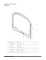
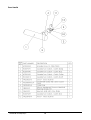
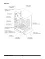
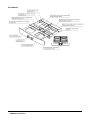
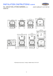
Skagen Skagen Cleanburn Stove Cleanburn Stove JINHCE08 revC 26/10/11 Installation & Operating Instructions Technical Specification Appliance Mass Total Efficiency Nominal Heat Output Mean CO Emission (@13% O2) Mean Flue Gas Temperature Flue Gas Mass Flow 125 kg 79.0 % 6.0 kW 0.16 % 280 °C 5.0 g/s This appliance is not for use in shared flue This appliance is suitable for intermittent burning JINHCE08 revB 03/10/11 Table of Contents General Guidance ............................................................................................................ 2 Competent Persons Scheme ........................................................................ 2 CO Alarms .................................................................................................. 2 Health & Safety Precautions ....................................................................... 2 Handling ...................................................................................................... 2 Fire Cement ................................................................................................. 2 Asbestos ...................................................................................................... 3 Metal Parts .................................................................................................. 3 Modification ................................................................................................ 3 Safety ............................................................................................................................... 3 Aerosols ...................................................................................................... 3 Fireguards ................................................................................................... 3 Do not Over-Fire ......................................................................................... 3 Fume Emission............................................................................................ 3 CO Alarm .................................................................................................... 4 In the Event of a Chimney Fire ................................................................... 4 Assembly Instructions ..................................................................................................... 5 Removal of Heat Shield .............................................................................. 5 Flue Collar .................................................................................................. 5 Blanking Plate ............................................................................................. 6 Rear Flue Pipe Installation .......................................................................... 6 Fitting of Heat Shield .................................................................................. 6 Removal of Internal Components ............................................................... 7 Side Bricks ............................................................................................................................................... 7 Rear Brick ................................................................................................................................................ 8 Baffle / Throat Plate Fitting ........................................................................ 8 Air Controls ................................................................................................ 8 Installation Instructions ................................................................................................... 9 Chimney ...................................................................................................... 9 Connection to the Chimney ........................................................................ 9 Flue Draught ............................................................................................. 10 Air Supply ................................................................................................. 10 Hearth/ Material Clearances ..................................................................... 10 Recessed Appliance................................................................................................................................ 11 Free-Standing Appliance ........................................................................................................................ 11 Commissioning & Handover .................................................................... 11 Operating Instructions ................................................................................................... 12 Aerosol Sprays .......................................................................................... 12 Air Controls .............................................................................................. 12 Primary Air............................................................................................................................................. 12 Secondary and Tertiary Air .................................................................................................................... 12 Riddling Grate ........................................................................................... 13 Notes on Wood burning ............................................................................ 13 JINHCE08 revB 03/10/11 Lighting the Stove ..................................................................................... 13 Reduced Combustion ................................................................................ 13 Recommended Fuels ................................................................................. 14 General Maintenance..................................................................................................... 15 Baffle......................................................................................................... 15 Stove Body ................................................................................................ 15 Glass Panel ................................................................................................ 15 Firebricks .................................................................................................. 15 Door Catch ................................................................................................ 15 Rope .......................................................................................................... 16 Chimney and Flue ways ............................................................................ 16 Periods of Prolonged Non-Use ................................................................. 16 Gaskets ...................................................................................................... 16 Troubleshooting ............................................................................................................ 16 Fire will not burn ...................................................................................... 16 Fire blazing out of control......................................................................... 17 Spares Information ........................................................................................................ 18 Door Spares ............................................................................................... 18 Door Handle .............................................................................................. 19 Body Spares .............................................................................................. 20 Air Controls .............................................................................................. 21 JINHCE08 revB 03/10/11 General Guidance It is important that your stove is correctly installed as Cleanburn cannot accept responsibility for any fault arising through incorrect use or installation. These instructions cover the basic principles to ensure satisfactory installation of the stove, although detail may need slight modification to suit particular local site conditions. The installation must comply with current Building Regulations, national and European standards, Local Authority byelaws and other specifications or regulations as they affect the installation of the stove. The Building Regulations requirements may also be met by adopting the relevant recommendations in the current issues of British Standards BS 8303 and BS EN 152871. Competent Persons Scheme Cleanburn recommend that this stove is installed by a member of an accredited competent persons scheme e.g. HETAS. If the installer is not a member of a competent persons scheme, it is a legal requirement to notify your local building control body in advance of any work starting. CO Alarms Building regulations require that whenever a new or replacement fixed solid fuel or wood/biomass appliance is installed in a dwelling, a carbon monoxide alarm must be fitted in the same room as the appliance. Further guidance on the installation of the carbon monoxide alarm is available in BS EN 50292:2002 and from the alarm manufacturer’s instructions. Provision of an alarm must not be considered a substitute for either installing the appliance correctly or ensuring regular servicing and maintenance of the appliance and chimney system. Health & Safety Precautions Special care must be taken when installing the stove such that the requirements of the Health and Safety at Work Act are met Handling Adequate facilities must be available for loading, unloading and site handling. Fire Cement Some types of fire cement are caustic and should not be allowed to come into contact with the skin. In case of contact, wash immediately with plenty of water. JINHCE08 revB 03/10/11 2 Asbestos This stove contains no asbestos. If there is a possibility of disturbing any asbestos in the course of installation then please seek specialist guidance and use appropriate protective equipment. Metal Parts When installing or servicing this stove, care should be taken to avoid the possibility of personal injury. Modification No unauthorized modification of this appliance should be carried out. Safety WARNING – This appliance will be hot when in operation and due care should be taken. The supplied operating tool or gloves may be used to open the door and operate the air controls. Aerosols Do not use an aerosol spray on or near the stove when it is alight. Fireguards Always use a fireguard in the presence of children, the elderly or the infirm. The fireguard should be manufactured in accordance with BS8423 – Fireguards for use with solid fuel appliances. Do not OverFire It is possible to fire the stove beyond its design capacity. This could damage the stove so watch for signs of overfiring. If any part of the stove starts to glow red, the stove is in an overfire situation and the controls should be adjusted accordingly. Never leave the stove unattended for long periods without first adjusting the controls to a safe setting. Careful air supply control should be exercised at all times. Fume Emission WARNING NOTE Properly installed, operated and maintained, this appliance will not emit fumes into the dwelling. The appliance door(s) must be kept closed at all times, except for when de-ashing and refueling, during which occasional fumes may occur. However, Persistent fume emission is potentially dangerous and must not be tolerated. If fume emission does persist, then the following immediate action should be taken: 1. 2. 3. 4. Open doors and windows to ventilate the room and then leave the premises. Let the fire go out. Check for flue or chimney blockage and clean if required. Do not attempt to re-light the fire until the cause of the fume emission has been identified and corrected. If necessary, seek expert advice. The most common cause of fume emission is flueway or chimney blockage. For your own safety these must be kept clean at all times. JINHCE08 revB 03/10/11 3 Adverse weather – In a small number of installations, occasional local weather conditions (e.g. wind from a particular direction) may cause downdraught in the flue and cause the stove to emit fumes. In these circumstances, the stove should not be used. A professional flue installer will be able to advise on solutions to this problem (e.g. anti-downdraught cowl). CO Alarm Your installer should have fitted a CO alarm in the same room as the appliance. If the alarm sounds unexpectedly, follow the instructions given under “Warning Note” above. Do not fit an extractor fan in the same room as this appliance. In the Event of a Chimney Fire Raise the alarm Call the Fire Brigade Close appliance air controls Move furniture, ornaments etc away Place a fireguard in front of stove Check the chimney breast for signs of excessive heat. Ensure the Fire Brigade can gain access to your roof space in order to check for fire spread. JINHCE08 revB 03/10/11 4 Assembly Instructions Instructions Removal of Heat Shield To remove the heat shield, remove the buttonhead screw and then To remove the heat shield, remove the button flex the heat shield by pulling the heat shield towards you until flex the heat shield by pulling the heat shield towards you until the righthand edge clears the stove body hand edge clears the stove body and pops out. Lift the left hand edge clear of the stove body and remove. and remove. Flue Collar Flue Collar Wind the eight M6 studs supplied into the fixing holes in the flue collar and blanking plate until finger tight. blanking plate until finger tight. Place the gasket in position on on either the top or rear outlet (as required), manoeuv manoeuvring the flue collar into position, taking care to line up the studs with taking care to line up the studs with the fixing holes. the fixing holes. Secure in place using the M6 nuts and washers. Fit the two M8 coach bolts in the flue collar to blank off the optional damper handle holes. bolts in the flue collar to blank off the optional damper handle holes. JINHCE08 revB 03/10/11 5 Blanking Plate Fit the Flue Gasket and Blanking Plate on the remaining free outlet Fit the Flue Gasket and Blanking Plate on the remaining free outlet. Secure it, using the M6 nuts and studs. studs. Heat Shield Knockout Rear Flue Pipe Installation the knockout in the rear heat shield must be For rear flue installations, the knock removed. Remove the heat shield as instructed heat shield as instructed on page 5. Carefully cut through the tabs holding the knockout section in the heat shield and remove. out section in the heat shield and remove. Carefully remove any sharp edges on the heat shield left behind by the left behind by the tabs. Fitting of Heat Shield Fitting of Heat Shield To fit the heat shield, position the lefthand edge and then flex the heat To fit the heat shield, position the left hand edge and then flex the heat shield until the righthand ri hand edge clears the stove body body and pops into place. Insert and lightly tighten the supplied buttonhead button screw to prevent any rattle. prevent any rattle. Do not over tighten the screw, as this will damage the heat shield shield JINHCE08 revB 03/10/11 6 Removal of Internal Components Removal of Internal Components The Fire Bricks, in this appliance, are factory fitted. fit The following set of diagrams diagrams show the removal sequence that you will need to employ when servicing your sequence that you will need to employ when servicing your stove. Side Bricks 1. Remove Front Plate by lifting it up out of the slots on either by lifting it up out of the slots on either side. Rotate to remove from the stove. side. Rotate to remove from the stove. 2. Remove all of the Grate Bars. Take care to notice which are the upper and which are the lower bars. This will allow correct replacement. 3. Slide the front edge of each Side Plate towards the centre of the stove. Lift the Side Plates and remove. the stove. Lift the Side Plates and remove. 4. Slide the bottom edge of the Side Bricks towards the centre of the stove. It may be necessary to rotate the cam bar to allow this. Once the Side Bricks are clear of the retaining tab at the top of the stove, they can be removed. top of the stove, they can be removed. JINHCE08 revB 03/10/11 7 Rear Brick Pull the top edge of each Rear Brick forward and lift the brick out of the Pull the top edge of Rear Brick forward and lift the brick out of the Stove. Stove. Baffle / Throat Plate Fitting hand end of the Baffle up, To install the Baffle, slide the lefthand end of the Baffle up, and over the support. Push the Baffle affle to the left until the righthand edge clears the other support. Slide the Baffle back hand edge clears the other support. Slide the Baffle back to the right until it sits centrally in the stove. Check that the two tabs at the front of the Baffle are between the Baffle Supports. Air Controls djust both control knobs to To remove the air controls, first adjust both control knobs to maximum m open (turn fully clockwise). Then, carefully pull the control unit forwards and remove it from the stove. Before refitting, fitting, adjust the controls to maximum open. ope Failure to do this may result in damage to the gasket material. JINHCE08 revB 03/10/11 8 Installation Instructions Chimney The chimney height and the position of the chimney terminal should conform to Building Regulations. Check that the chimney is in good condition, dry, free from cracks and obstructions. The diameter of the flue should not be less than 150mm and not more than 200mm. If any of these requirements are not met, the chimney should be lined by a suitable method. If there is no existing chimney then either a prefabricated block chimney in accordance with Building Regulations Approved Document J, or a twinwalled insulated stainless steel flue to BS EN 1856 can be used. These chimneys must be fitted in accordance with the manufacturer’s instructions and Building Regulations. If the chimney is believed to have previously served an open fire installation, it is possible that the higher flue gas temperature from the stove may loosen deposits that were previously firmly adhered, with the consequent risk of flue blockage. It is therefore recommended that the chimney is swept a second time within a month of regular use after installation. If you have any doubts about the suitability of your chimney, consult your local dealer/stockist. Connection to the Chimney The chimney must be swept before connection to the stove. An existing fireplace opening can be bricked up or sealed with a register plate. A short length of flue pipe of minimum 150mm internal diameter may then be used to connect the stove to the chimney. This flue pipe should be made of 316 grade stainless steel or vitreous enamelled steel, nominal thickness 1.2mm. Ensure that the pipe end is no closer than 76mm to the chimney walls. The length of any horizontal run of flue pipe must not exceed 150mm. It is essential that all connections between the stove and chimneyflue are sealed and made airtight. Both the chimney and flue pipe must be accessible for cleaning and if ANY part of the chimney cannot be reached through the stove (with baffle removed), a soot door must be fitted in a suitable position. JINHCE08 revB 03/10/11 9 Flue Draught If the draught exceeds the recommended maximum, a draught stabiliser must be fitted so that the rate of burning can be controlled and to prevent over firing. If the reading is less than the recommended minimum then the performance of the appliance will be compromised. The flue draught should be checked under fire at high output. Minimum Draught – 1.2mm Water Gauge Maximum Draught – 2.5mm Water Gauge Air Supply The room or space containing this appliance should have purpose provided ventilation (where necessary) in accordance with Building Regulations. Due consideration should be given to air requirements for any other appliance in the same room or space. Any air opening must be kept clear from blockage or obstruction. Hearth/ Material Clearances Your stove must be installed on a floor with adequate loadbearing capacity, otherwise suitable measures should be taken. Use the adjusting screws in the feet to level the stove. All noncombustible walls closer than 300mm to the stove should be at least 75mm thick. Minimum Distances to Combustible Material Behind the Stove 250mm At the Side of the Stove 200mm To Furniture 800mm Note: combustible material refers to any material that will degrade when subjected to heat e.g. plaster. No combustible material must be stored underneath the stove. Warning! Please ensure that there is sufficient clearance to combustible material from the stove and connecting flue pipe. Clearance distances to the stove and flue pipes specified in Document J of Building Regulations as well as any other relevant legislation should be followed. JINHCE08 revB 03/10/11 10 Recessed Appliance The stove can be recessed into a suitably sized fireplace with a minimum 50mm clearance all around, but The stove can be recessed into a suitably sized fireplace with a minimum 50mm clearance all around we recommend that a free air gap of 150 mm is left around the sides and top of the stove and at least 50mm at the back of the stove to obtain maximum heat output and for access to the rear of the stove. 50mm at the back of the stove to obtain maximum heat output and for access to the rear of the stove. The hearth should extend at least 225 mm from The hearth should extend at least 225 mm from the front of the stove. If If the stove is to stand in an appliance recess, it should stand wholly above a solid, noncombustible non hearth, at least 125 mm thick (this may include the thickness of a solid floor). hearth, at least 125 mm thick (this may include the thickness of a solid floor). FreeStanding Appliance If the stove is not to stand in an appliance recess, it may stand wholly above a hearth made of non non combustible board / sheet material or tiles, at least 12mm thick. combustible board / sheet material or tiles, at least 12mm thick. The hearth should extend at least 150 mm from the sides and rear of the stove, and at least 225 mm from the front of the stove. Commissioning & Handover Upon completion of the installation, allow a suitable period of time for any fire cement and mortar to dry out. A small fire may then be lit and checked to ensure the smoke and fumes are taken from the stove up the A small fire may then be lit and checked to ensure the smoke and fumes are taken from the stove u chimney and emitted safely to atmosphere. chimney and emitted safely to atmosphere. Do not run the stove at full output for at least 24 hours. Do not run the stove at full output for at least 24 hours. On completion of the installation and commissioning, ensure that the operating instructions and operating tools for the stove are left with the cust tools for the stove are left with the customer. Advise the customer on the correct use of the appliance with the fuels likely to be used on the stove and warn them to use only the recommended fuels for the stove. warn them to use only the recommended fuels for the stove. Advise the user on what to do should smoke or fumes be emitted from the stove. Advise the user on what to do should smoke or fumes be emitted from the stove. The user should be warned to use a fireguard to BS 8423 in the presence of children and/or infirm persons. user should be warned to use a fireguard to BS 8423 in the presence of children and/or infirm persons. user should be warned to use a fireguard to BS 8423 in the presence of children and/or infirm persons. JINHCE08 revB 03/10/11 11 Operating Instructions This appliance is not suitable for use in a shared flue This appliance should not be operated with the doors open Aerosol Sprays Do not use an aerosol spray on or near the stove when it is alight. Air Controls This stove has been designed to burn far more efficiently than a traditional stove, with the obvious notable feature of clean glass. However, for this product to work properly it must be used correctly. It is essential that the stove has an adequate air supply for combustion and ventilation. Primary Air Control Secondary and Tertiary Air Control Primary Air Primary air is controlled via the lefthand control knob. Turning it clockwise increases the amount of Primary Air. This provides a conventional air draught to the bed of the fire. Secondary and Tertiary Air Secondary and Tertiary air is controlled via the righthand control knob. Turning it clockwise increases the amount of Secondary and Tertiary air. The Secondary air provides “Airwash” that keeps a clean and uninterrupted view of the fire. Tertiary air aids in good secondary combustion of the fuel and reducing emissions into the chimney and environment. Warning! This Appliance will be hot when in operation and due care should be taken. We advise that suitable gloves are used when operating the Primary and Secondary air controls, and when opening the door. JINHCE08 revB 03/10/11 12 Riddling Grate Your Cleanburn stove is fitted with a locomotive type grate. So that deashing can be carried out cleanly and easily, it is riddled from the outside of the stove with the doors closed. To burn wood, push the operating tool up and away from you. When left in this position, air is restricted through the bed of the fire providing a solid base to build up a bed of ash. It might prove beneficial when burning more reactive fuels to leave the grate in a “neutral” position, thus directing some under fire air and some over fire air to the firebed. Notes on Wood burning With a 1.75kg load of wood, the stove will need to be refuelled approximately once every hour. Wood can be stacked in the stove, but care must be taken that logs do not touch the baffle. Wood burns most efficiently with the secondary air control in the open position and the primary control closed. Adjusting the secondary control will control the burn rate of the stove. Note primary and secondary air is needed to light the stove, see section entitled ‘Lighting the Stove’ Lighting the Stove We recommend that you have two or three small fires before you operate your stove to its maximum heat output. This is to allow the paint to cure in steadily and to give a long service life of the paint finish. During this curing in process you may notice an unpleasant smell. It is nontoxic, but for your comfort we would suggest that during this period you leave all doors and windows open. First, load the fire with starting fuel, i.e. paper, dry sticks and/or firelighters. Light the fire at the base leaving all air controls open. Allow the fuel to reach a steady glow and build the fire up gradually. Once you have a good fire established across the grate bed, further fuel can be added as required. Reduced Combustion In order to shut down the stove, close the primary control, then close the secondary air by turning the knobs fully anticlockwise. If the controls are left in this position, the fire will be starved of air and will die down. If you want to revive the fire it is recommended that the primary air control is open first, and then operate the secondary air control. Warning! The stove will remain hot for a considerable time after the fire has been extinguished. JINHCE08 revB 03/10/11 13 Recommended Fuels Cleanburn recommend that wood logs are burnt in this appliance. Burn only dry, wellseasoned wood, which should have been cut, split and stacked for at least 12 months, with free air movement around the sides of the stack to enable it to dry out. Burning wet or unseasoned wood will create tar deposits in the stove and chimney and will not produce a satisfactory heat output. Only authorised smokeless fuels may be used in smoke control areas. Warning! Petroleum coke fuels or household waste must not be burnt on this appliance. This appliance should not be used as an incinerator. No liquid fuels should be burnt on this appliance. Should any difficulties arise over fuel quality or suitability, consult your local approved coal merchant or: HETAS Ltd – Telephone 01242 673257 – www.hetas.co.uk Solid Fuel Association – Telephone 0800 600 000 – www.solidfuel.co.uk JINHCE08 revB 03/10/11 14 General Maintenance This Appliance requires regular maintenance by a competent engineer. Baffle This should be removed and cleaned at least once a month to prevent any build up of soot or fly ash that could lead to blocked flue ways and dangerous fume emission. If the baffle is removed the chimney/flue way can be swept through the appliance. Stove Body The stove is finished with a heat resistant paint and this can be cleaned with a soft brush. Do not clean whilst the stove is hot. The finish can be renovated with Cleanburn stove paint. Glass Panel Clean the glass panel when cool with proprietary glass cleaner. Highly abrasive substances should be avoided as these can scratch the glass and make subsequent cleaning more difficult. Wet logs on heated glass, a badly aimed poker or heavy slamming of the door could crack the glass panel. The glass will not fracture from heat. Firebricks In normal use, these can last for many years. It is possible however, to crack them if logs are continually jammed against them or if they are frequently struck with a poker. Check periodically for seriously cracked bricks, which can be replaced with new, available from your dealer. Door Catch The door catch may require adjustment to maintain the door seal. To adjust the catch: Loosen the M6 grub screw. Rotate the catch shaft one complete turn to achieve the correct door operation. Tighten the grub screw. JINHCE08 revB 03/10/11 15 Rope Check the rope around the door. If rope is becoming detached, use Cleanburn rope glue to reattach it. If the rope is in a poor condition, a replacement rope kit may be ordered from the Cleanburn stoves spares range. Chimney and Flue ways It is important that the chimney, flue ways and any connecting flue pipe are swept regularly. This means at least once a year for smokeless fuels and at least twice a year for wood and other fuels. The baffle will need to be removed from its supports in order to sweep the chimney (see assembly instructions). Only wirecentred sweeps’ brushes fitted with a guide wheel should be used. If it is not possible to sweep all parts of the chimney through the appliance, ensure there is adequate access to cleaning doors. Periods of Prolonged NonUse If the stove is to be left unused for a prolonged period of time then it should be given a thorough clean to remove ash and unburned fuel residues. To enable a good flow of air through the appliance to reduce condensation and subsequent damage, leave the air controls fully open Glass Gasket The glass gasket used on this appliance is produced from a heat resistant material called Manniglas. The glass gasket will have to be replaced when a new piece of glass is fitted as the gaskets become brittle after firing the stove. Over time you may also find that the gasket changes colour. This is due to a reduction in the pigment used in the manufacture of the product and no cause for concern. Troubleshooting Fire will not burn Check that: The air inlet is not obstructed in anyway. Chimneys and flue ways are clear. A suitable fuel is being used. There is an adequate air supply into the room. An extractor fan is not fitted in the same room as the stove. Flue draught is above minimum level (see installation instructions). JINHCE08 revB 03/10/11 16 Fire blazing out of control Check that: The doors are tightly closed. The air controls are all in the closed position. A suitable fuel is being used. The glass retaining clips are not loose. The door rope seals are in good condition Flue draught is below maximum level (see installation instructions). JINHCE08 revB 03/10/11 17 Spares Information Door Spares JINHCE08 revB 03/10/11 18 Door Handle JINHCE08 revB 03/10/11 19 Body Spares JINHCE08 revB 03/10/11 20 Air Controls 21 JINHCE08 revB 03/10/11