1
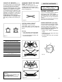
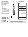
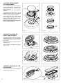
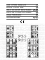
PIANI COTTURA DA INCASSO
IT
BUILT-IN COOKING HOBS
GB
TABLES DE CUISSON ENCASTRABLES
FR
BE
PLACAS DE COCCIÓN EMPOTRABLES
ES
FOGÃO POR ENCAIXE
PT
INBOUWKOMFOREN
BE
NL
TRUZIONI PER L’USO • INSTRUCTIONS FOR USE • MODE D’EMPLOI • INSTRUCCIONES PA
• MANUAL DE USO • ISTRUZIONI PER L’USO • INSTRUCTIONS FOR USE • MODE D’EMP
RUCCIONES PARA EL USO • MANUAL DE USO • ISTRUZIONI PER L’USO • INSTRUCTIONS
• MODE D’EMPLOI • INSTRUCCIONES PARA EL USO • MANUAL DE USO • ISTRUZIONI P
O • INSTRUCTIONS FOR USE • MODE D’EMPLOI • INSTRUCCIONES PARA EL USO • MAN
• ISTRUZIONI PER L’USO • INSTRUCTIONS FOR USE • MODE D’EMPLOI • INSTRUCCIONE
SO • MANUAL DE USO • ISTRUZIONI PER L’USO • INSTRUCTIONS FOR USE • MODE D’E
RUCCIONES PARA EL USO • MANUAL DE USO • ISTRUZIONI PER L’USO • INSTRUCTIONS
• MODE D’EMPLOI • INSTRUCCIONES PARA EL USO • MANUAL DE USO• ISTRUZIONI PE
STRUCTIONS FOR USE • MODE D’EMPLOI • INSTRUCCIONES PARA EL USO • MANUAL D
UZIONI PER L’USO • INSTRUCTIONS FOR USE • MODE D’EMPLOI • INSTRUCCIONES PARA
• MANUAL DE USO • ISTRUZIONI PER L’USO • INSTRUCTIONS FOR USE • MODE D’EMP
RUCCIONES PARA EL USO • MANUAL DE USO • ISTRUZIONI PER L’USO • INSTRUCTIONS
• MODE D’EMPLOI • INSTRUCCIONES PARA EL USO • MANUAL DE USO • ISTRUZIONI P
O • INSTRUCTIONS FOR USE • MODE D’EMPLOI • INSTRUCCIONES PARA EL USO • MAN
• ISTRUZIONI PER L’USO • INSTRUCTIONS FOR USE • MODE D’EMPLOI • INSTRUCCION
SO • MANUAL DE USO• ISTRUZIONI PER L’USO • INSTRUCTIONS FOR USE • MODE D’EM
RUCCIONES PARA EL USO • MANUAL DE USO • ISTRUZIONI PER L’USO • INSTRUCTIONS
• MODE D’EMPLOI • INSTRUCCIONES PARA EL USO • MANUAL DE USO • ISTRUZIONI P
O • INSTRUCTIONS FOR USE • MODE D’EMPLOI • INSTRUCCIONES PARA EL USO • MAN
• ISTRUZIONI PER L’USO • INSTRUCTIONS FOR USE • MODE D’EMPLOI • INSTRUCCIONE
SO • MANUAL DE USO• ISTRUZIONI PER L’USO • INSTRUCTIONS FOR USE • MODE D’EM
RUCCIONES PARA EL USO • MANUAL DE USO • ISTRUZIONI PER L’USO • INSTRUCTIONS
• MODE D’EMPLOI • INSTRUCCIONES PARA EL USO • MANUAL DE USO • ISTRUZIONI P
O • INSTRUCTIONS FOR USE • MODE D’EMPLOI • INSTRUCCIONES PARA EL USO • MAN
• ISTRUZIONI PER L’USO • INSTRUCTIONS FOR USE • MODE D’EMPLOI • INSTRUCCION
SO • MANUAL DE USO • ISTRUZIONI PER L’USO • INSTRUCTIONS FOR USE • MODE D’E
RUCCIONES PARA EL USO • MANUAL DE USO• ISTRUZIONI PER L’USO • INSTRUCTIONS
6
5
4
0
3
1
2
P60
P90
6
5
4
0
3
1
2
ITALIANO
Istruzioni per l’uso
Pagina
3
La Casa Costruttrice non risponde delle possibili inesattezze, imputabili ad errori di stampa o trascrizione, contenute nel presente libretto. Si riserva il diritto, pregiudicare le caratteristiche essenziali di funzionalità e sicurezza, di apportare ai propri prodotti, in qualunque
momento e senza preavviso, le eventuali modifiche opportune per qualsiasi esigenza di carattere costruttivo o commerciale.
ENGLISH
Instructions for use
Page
19
The manufacturer cannot be held responsible for possible inaccuracies due to printing or transcription errors in the present booklet.
The manufacturer reserves the right to make all modifications to its products deemed necessary for manufacture or commercial reasons at any moment and without prior notice, without jeopardising the essential functional and safety characteristics of the appliances.
FRANÇAIS
Note d’emploi
Page
33
Le fabricant n’est pas responsable des erreurs éventuelles, dues à des fautes de frappe ou d’impression, susceptibles de se trouver
dans cette notice.
Il se réserve le droit, sans porter préjudice aux caractéristiques essentielles, du point de vue fonctionnel et du point de vue sécurité,
d’apporter à ses produits, à tout moment et sans préavis, toutes les modifications éventuellement nécessaires pour faire face à des
exigences de fabrication ou de commercialisation.
ESPAÑOL
Instrucciones para el uso
Página
47
La casa constructora no responde por los posiles errores de impresion o de transcripción, contenidos en el presente manual.
Se reserva el derecho, sin comprometer las características esenciales de funcionalidad y seguridad, de aportar a sus propios prodúctos, en cualquier momento y sin preaviso, eventuales modificaciones oportunas para cualquier exigencia de carácter constructivo
o comercial.
PORTUGUÊS
Instrucoes para o uso
Página
61
O fabbricante não reponde pelas possiveis inesatesas, imputabilidades e erros de impressão ou transcrições contidas no presente
manual.
Se reserva o direito, sem prejudicar a característica essencial de funcionalidade e segurança, de produzir nos proprios produtos em
qualquer momento e sem aviso previo, eventuais modificações oportunas para as exigências de caracter construtivo ou comercial.
NEDERLAND
2
Gebruiksaanwijzing
Bladzijde
75
De fabrikant kan niet aansprakelijk gesteld worden voor onwaarheden in deze folder veroorzaakt door druk- of vertaalfouten. De fabrikant heeft het recht alle wijzigingen aan het produkt aan te brengen die zij voor commerciële- of fabricagedoeleinden noodzakelijk acht,
op ieder moment en zonder voorafgaande kennisgeving.
ENGLISH
Instructions for use
Dear Customer,
Thank you for having purchased and given your preference to our product.
The safety precautions and recommendations reported below are for your own safety and that of others. They will also provide a
means by which to make full use of the features offered by your appliance.
Please preserve this booklet carefully. It may be useful in future, either to yourself or to others in the event that doubts should arise
relating to its operation.
This appliance must be used only for the task it has explicitly been designed for, that is for cooking foodstuffs. Any other form
of usage is to be considered as inappropriate and therefore dangerous.
The manufacturer declines all responsibility in the event of damage caused by improper, incorrect or illogical use of the appliance.
IMPORTANT PRECAUTIONS AND RECOMMENDATIONS
✓ After having unpacked the appliance, check to ensure that it is not
damaged.
If you have any doubts, do not use it and consult your supplier or a
professionally qualified technician.
✓ Packing elements (i.e. plastic bags, polystyrene foam, nails, packing straps,
etc.) should not be left around within easy reach of children, as these may
cause serious injuries.
✓ The packaging material is recyclable and is marked with the recycling
symbol
.
✓ Do not attempt to modify the technical characteristics of the appliance as
this may become dangerous to use.
✓ The manufacturer cannot be considered responsible for damage caused by
unreasonable, incorrect or rash use of the appliance.
✓ If you should decide not to use this appliance any longer (or decide to
substitute an older model), before disposing of it, it is recommended that it
be made inoperative in an appropriate manner in accordance to health and
environmental protection regulations, ensuring in particular that all
potentially hazardous parts be made harmless, especially in relation to
children who could play with old appliances.
✓ The appliance should be installed and all the gas/electrical connections
made by a qualified engineer in compliance with local regulations in force
and following the manufacturer's instructions
TIPS FOR THE USER
✓ During and after use of the cooktop, certain parts will become very hot. Do not
touch hot parts.
✓ Keep children away from the cooking hob when it is in use.
✓ After use, ensure that the knobs are in position ● (off), and close the main gas
delivery valve or the gas cylinder valve.
✓ In case of difficulty in the gas taps operation, call Service.
✓ Before any cleaning or maintenance, switch off the electricity to the cooktop.
Risk of fire!
✓ Do not leave inflammable material on the cooktop.
✓ Make sure that the electrical cables of other appliances installed nearby
cannot come into contact with the cooktop.
✓ Never cook the food directly on the electric hotplates, but in special pans or
containers.
IMPORTANT PRECAUTIONS
AND RECOMMENDATIONS
FOR USE OF ELECTRICAL
APPLIANCES
Use of any electrical appliance implies
the necessity to follow a series of
fundamental rules. In particular:
✓ Never touch the appliance with wet
hands or feet;
✓ do not operate the appliance
barefooted;
✓ do not allow children or disabled
people to use the appliance without
your supervision.
The manufacturer cannot be held
responsible for any damages caused
by improper, incorrect or unreasonable
use of the appliance.
DECLARATION OF CE
CONFORMITY
– This cooking hob has been designed
to be used only for cooking. Any other
use (such as heating a room) is
improper and dangerous.
– This cooking hob has been designed,
constructed, and marketed in
compliance with:
- Safety requirements of the "Gas"
Directive 90/396/EEC;
- Safety requirements of EEC Directive
“Low voltage” 73/23
(gas or gas/electric appliances);
- Safety requirements of EEC Directive
“EMC” 89/336
(gas or gas/electric appliances);
- Requirements of EEC Directive
93/68.
These instructions are only valid
for the countries indicated by the
symbols on the cover of the
instruction booklet and on the
appliance itself.
19
1
FEATURES
14
20
12
19
10
18
22
22
Fig. 1.1a
Fig. 1.2a
14
14
13
13
12
10
10
22
22
Fig. 1.1b
12
Fig. 1.2b
14
14
13
11
13
11
22
10
22
Fig. 1.1c
12
10
Fig. 1.2c
21
14
14
13
12
10
6
4
0
3
1
20
15
5
17
12
22
10
22
2
Fig. 1.1d
Fig. 1.2d
The appliance has class 3
14
11
13
12
16
NOTE:
✓ If the appliance has a safety valve system fitted
(beside every burner is a T-shaped probe, as in Fig.
3.1 - not to be confused with the S-shaped
electrode of the gas-lighter), the flow of gas will be
stopped if and when the flame should accidentally
go out.
10
22
Fig. 1.2e
COOKING POINTS
6
5
4
0
3
1
21
17
2
14
13
12
10
1.
2.
3.
4.
5.
6.
Auxiliary burner (A)
Semirapid burner (SR)
Rapid burner (R)
Triple ring burner (TR)
Fish burner (PS)
Electric plate
- normal (1000 W)
- rapid (1500 W)
-
1,00
1,75
3,00
3,50
2,95
kW
kW
kW
kW
kW
22
Fig. 1.2f
DESCRIPTION CONTROL PANEL
10.
11.
12.
13.
14.
15.
16.
17.
18.
19.
20.
21.
22.
Auxiliary burner control knob (1)
Rapid burner control knob (3)
Triple ring burner control knob (4)
Left semirapid burner control knob (2)
Right semirapid burner control knob (2)
Central fish-burner control knob (5)
Central auxiliary burner control knob (1)
Electrical plate control knob (6)
Right triple ring burner control knob (4)
Left triple ring burner control knob (4)
Central semirapid burner control knob (2)
Electrical plate indicator light
Electric gas-lighting device;
if the device is not installed, the appliance may be provided with:
- A gas-lighter incorporated into the knob (★ symbol beside flame
- No gas-lighter (no ★ symbol beside knobs).
- max. heat/max. gas flow).
CAUTION:
If the burner is accidentally extinguished, turn the gas off at the control knob and wait at least 1 minute before attempting to relight.
CAUTION:
Gas hobs produce heat and humidity in the environment in which they are installed.
Ensure that the cooking area is well ventilated by opening the natural ventilation grilles or by installing an extractor hood connected
to an outlet duct.
CAUTION:
If the hob is used for a prolonged time it may be necessary to provide further ventilation by opening a window or by increasing the
suction power of the extractor hood (if fitted).
21
2
HOW TO USE THE COOKER TOP
GAS BURNERS
Gas flow to the burners is adjusted by turning the knobs (illustrated in figs. 2.1a 2.1b) which control the safety valves.
Turning the knob so that the indicator line
points to the symbols printed on the panel
achieves the following functions:
– full circle
●
= closed valve
– symbol
or
= maximum
aperture or flow
– symbol
Fig. 2.1a
= minimum
aperture or flow
✓ To reduce the gas flow to minimum,
rotate the knob further anti-clockwise
to point the indicator towards the small
flame symbol.
✓ The maximum aperture position permits rapid boiling of liquids, whereas
the minimum aperture position allows
slower warming of food or maintaining
boiling conditions of liquids.
✓ Other intermediate operating adjustments can be achieved by positioning
the indicator between the maximum
and minimum aperture positions, and
never between the maximum aperture
and closed positions.
N.B. If your local gas supply makes it difficult to light the burner with the knob set
to maximum, set the knob to minimum
and repeat the operation.
LIGHTING GAS BURNERS FITTED WITH SAFETY VALVE
DEVICE
In order to light the burner, you must:
1 – Turn the knob fig. 2.1b in anti-clockwise direction up to the maximum
aperture (symbol
), push in and
hold the knob; this will light the gas.
In case of black-out, bring a lighted
match close to the burner.
2 – Wait about ten seconds after the
gaslights before releasing the knob
(starting time for the valve).
3 – Adjust the gas valve to the desired
position.
If the burner flame should go out for some
reason, the safety valve will automatically stop the gas flow.
To re-light the burner, return the knob to
the closed ● position, wait for at least 1
minute and then repeat the lighting procedure.
Fig. 2.1b
LIGHTING GAS BURNERS
Models without electric ignition
To light one of the gas burners, hold a
flame (e.g. a match) close to the top part
of the burner, push in and turn the
relative knob in an anti-clockwise
direction (fig. 2.3), pointing the knob
indicator towards the large flame symbol
(i.e. max. gas flow).
Models fitted with electric spark
lighter button
Fig. 2.2
On these cooker tops, to light one of the
burners you have to push in and turn the
relative knob to the maximum aperture
position (large flame symbol
) and
press the electric lighter button (fig. 2.2)
until the flame has been lit.
Adjust the gas valve to the desired position.
Models fitted with electric lighter
incorporated into the burner
knobs
The electric ignition is incorporated in the
knobs (★ symbol beside flame
- max.
heat/max. gas flow fig. 2.1b).
To light one of the gas burners, push in
and turn the relative knob to the maximum aperture position (large flame
symbol) and hold the knob in until the
flame has been lit.
22
Fig. 2.3
The sparks produced by the lighter situated inside the relative burner will light the
flame. Adjust the gas valve to the desired position.
N.B. When the cooker top is not
being used, set the gas knobs to
their closed positions and also
close the cock valve on the gas
bottle or the main gas supply line.
CHOICE OF BURNER
(fig. 2.4)
The symbols printed on the panel beside
the gas knobs indicate the correspondence between the knob and the burner.
The most suitable burner is to be chosen
according to the diameter and volume
capacity of the container to be warmed.
It is important that the diameter of the
pots or pans suitably match the heating
potential of the burners in order not to
jeopardise the efficiency of the burners,
bringing about a waste of gas fuel.
A small diameter pot or pan placed on a
large burner does not necessarily mean
that boiling conditions are reached quicker.
AUXILIARY GRATE FOR SMALL
PANS “On request“ (fig. 2.5).
This grate is to be placed on top of the
(smaller) auxiliary burner when using
small diameter pans, in order to prevent
them from tipping over.
Never cook food directly on the
electric hotplates! Always use a
saucepan or special container.
NORMAL HOTPLATE
To turn on the electric hotplate, rotate the
knob (fig. 2.7) o the desired setting.
The numbers from 1 to 6 indicate the
operating positions with increasing number corresponding to higher temperature
settings.
When the pan comes to the boil, turn the
heat down to the level desired.
Fig. 2.5
SPECIAL WOK GRILLE”
“On request“ (fig. 2.6a e 2.6b)
This special grille for woks should be
placed over the pan-rest for the triple ring
burner.
Warning:
✓ Using woks without this special grille
may cause the burner to malfunction.
✓ Do not use the grille for ordinary, flatbottomed saucepans.
Fig. 2.4
ELECTRIC HOTPLATES
RAPID HOTPLATE (red dot)
The rapid hotplate control knob is similar
to that of the normal hotplate, with 6
selectable heating positions (fig. 3.1).
The characteristics of this hotplate, which
is also equipped with a thermostatic cutoff device, make it possible to:
✓ achieve the cooking temperature
rapidly
✓ make full use of its output power using
flat-bottomed pans
✓ limit the output power with unsuitable
saucepans.
DIAMETERS OF PANS WHICH
MAY BE USED ON THE HOBS
BURNERS
MINIMUM
MAX.
* Auxiliary
12 cm
14 cm
Semirapid
16 cm
24 cm
Rapid
24 cm
26 cm
Triple-ring
26 cm
28 cm
6
5
4
WRONG
0
Fish burner from 12x30 to 18x40 cm
3
Maximum diameter for woks: 36 cm
1
* with grill for small cookware:
minimum diameter: 6 cm
2
Fig. 2.7
do not use pans with concave or convex bases
Fig. 2.6a
CORRECT
Caution!
the cooking hob becomes very
hot during operation.
Keep children well out of reach.
Fig. 2.6b
23
PROPER USE OF THE ELECTRIC HOTPLATE (fig. 2.8)
When the pan comes to the boil, turn the
heat down to the level desired.
Remember that the hotplate will continue
to produce heat for about five minutes
after it has been turned off.
While using the electric hotplate, you
must:
✓ avoid keeping it on without something
on it;
✓ avoid pouring liquids on it while it is
hot;
✓ use flat-bottomed (electric hotplate
type) pots and pans only
✓ use cooking receptacles which cover
as much of the surface of the hotplate
as possible.
✓ to save electricity, use lids whenever
possible.
✓ never cook food directly on the hotplate: always use a pan or suitable container.
An indicator light located on the control
panel signals that the hotplate is operating.
ELECTRIC HOTPLATE
USAGE TABLE
Hob controlled by
7-position
switch
0-6
Position
of switch
1
0
Switched OFF
1
2
For melting operations
(butter, chocolate).
2
To maintain food hot and to
heat small quantities of liquid
(sauces, eggs).
3
To heat bigger quantities; to
whip creams and sauces.
(vegetables, fruits, soups).
3
4
Slow boiling, i.e.:
meats, spaghetti,
continuations of
cooking of roasts,
potatoes.
4
For every kind of frying, cutlets, uncovered cooking, i.e.:
risotto.
4
5
Browning of meats, roasted
potatoes,
fried
fish,
omelettes, and for boiling
large quantities of water.
6
Fast frying, grilled steaks,
etc.
2
3
4
5
6
= Warming
= Cooking
= Roasting - Frying
Fig. 2.9
Fig. 2.8
24
TYPE OF COOKING
Caution! the cooking hob becomes very hot during operation.
Keep children well out of reach.
boiled
soups,
steam,
stews,
3
CLEANING AND MAINTENANCE
GENERAL ADVICE
GLASS LID (optional)
✓ Before you begin cleaning you must ensure that the hob
is switched off.
✓ It is advisable to clean when the appliance is cold and especially when cleaning the enamelled parts.
✓ All enamelled surfaces have to be washed with soapy water or
some other non-abrasive product with a sponge and are to be
dried preferably with a soft cloth.
✓ Avoid leaving alkaline or acid substances (lemon juice, vinegar etc.) on the surfaces.
✓ Do not close the glass lid when the electrical plates are still
hot and when the oven, installed below the cooking hob is on
or still hot.
✓ Do not rest hot pans or heavy objects on the cooker lid.
✓ Remove any spillages from the surface of the lid before
opening.
CLEANING ELECTRIC HOTPLATES
ENAMELLED PARTS
✓ All the enamelled parts must be cleaned with a sponge and
soapy water only or other non-abrasive products.
✓ Dry preferably with a chamois leather.
If acid substances such as lemon juice, tomato conserve,
vinegar etc. are left on the enamel for a long time they will etch
it, making it opaque.
✓ Always clean when the hotplate is tepid.
✓ Use a soft cloth, dampened with water, and a little salt. To
finish off, use a soft cloth with a little oil.
✓ Do not use water, to avoid the formation of rust.
BURNERS AND GRIDS
STAINLESS STEEL ELEMENTS
✓ Stainless steel parts must be rinsed with water and dried with
a soft and clean cloth or with a chamois leather.
✓ For persistent dirt, use specific non-abrasive products available commercially or a little hot vinegar.
✓ Note: regular use could cause discolouring around the
burners, because of the high flame temperature.
CONTROL KNOB
✓ The control knobs may be removed for cleaning but care
should be taken not to damage the seal.
✓ These parts can be removed and cleaned with appropriate
products.
✓ After cleaning, the burners and their flame spreaders must be
well dried and correctly replaced.
✓ It is very important to check that the burner flame spreader
and the cap have been correctly positioned. Failure to do so
can cause serious problems.
✓ In the models with safety device, check that the probe next to
each burner is always clean to ensure correct operation of the
safety valves.
✓ In appliances with electric ignition keep the electrode clean so
that the sparks always strike.
✓ Note: To avoid damage to the electric ignition do not use
it when the burners are not in place.
GAS TAPS
✓ Periodic lubrication of the gas taps must be carried out by
specialist personnel only.
✓ In the event of operating faults in the gas taps, call the
Service Department.
Do not use steam jet cleaners because the humidity
could infiltrate into the appliance making it dangerous.
25
CORRECT REPLACEMENT
OF THE BURNERS
It is very important to check that the
burner flame spreader “F” and the cap
“C” have been correctly positioned (see
figs. 3.1 and 3.2 ).
Failure to do so can cause serious
problems.
In appliances with electric ignition, check
that the electrode “S” (fig. 3.1) is always
clean to ensure trouble-free sparking.
C
F
In the models with safety device, check
that the probe “T” (fig. 3.1) next to each
burner is always clean to ensure correct
operation of the safety valves.
Both the probe and ignition plug must
be very carefully cleaned.
T
S
Fig. 3.1
Fig. 3.2
CORRECT POSITION OF
TRIPLE RING BURNER
The triple ring burner must be correctly
positioned (see fig. 3.3); the burner rib
must be fitted in their housing as shown
by the arrow.
The burner correctly positioned must not
rotate (fig. 3.4).
Then position the cap A and the ring B
(fig. 3.4 - 3.5).
Fig. 3.3
A
B
Fig. 3.4
CORRECT POSITION OF THE
FISH BURNER
This burner must be correctly positioned
as shown in the figure 3.6.
Fig. 3.6
26
Fig. 3.5
Installation advice
4
INSTALLATION
IMPORTANT
✓ The appliance should be installed, regulated and adapted to
function with other types of gas by a QUALIFIED INSTALLATION TECHNICIAN.
Failure to comply with this condition will render the guarantee invalid.
✓ The appliance must be installed in compliance with regulations in force.
✓ Installation technicians must comply to current laws in force
concerning ventilation and the evacuation of exhaust gases.
✓ Always unplug the appliance before carrying out any maintenance operations or repairs.
✓ The appliance must be housed in heat-resistant units.
✓ These tops are designed to be embedded into kitchen
fixtures measuring 600 mm in depth.
✓ The walls of the units must not be higher than work top
and must be capable of resisting temperatures of 105
°C above room temperature.
✓ Do not instal the appliance near inflammable materials
(eg. curtains).
TECHNICAL INFORMATION FOR THE INSTALLER
In order to install the cooker top into
the kitchen fixture, a hole with the
dimensions shown in fig. 4.1 (for cooker top P90) o 4.2 (for cooker top P60)
has to be made, bearing in mind the
following:
500
✓ within the fixture, between the
bottom side of the cooker top and
the upper surface of any other
appliance or internal shelf there
must be a clearance of at least 30
mm;
✓ the cooker top must be kept no less
than 200 mm away from any side
wall (figs. 4.1 - 4.2).
200
860
60
min
840
0
48
0
–2
min
0
–2
Fig. 4.1
✓ the hob must be installed at least
60 mm from the wall.
✓ there must be a distance of at least
650 mm between the hob and any
wall cupboard or extractor hood
positioned immediately above (see
figs. 4.3-4.4).
500
580
✓ It is absolutely essential that you
place a separator between the base
of the hob and the drawer unit.
60
✓ if the hob is installed over a built-in
oven, there must be a distance of at
least 30 mm between the two appliances. The two appliances should
be connected to the gas supply with
independent connections.
200
0
48
560
0
–2
0
–2
Fig. 4.2
27
The room where the gas appliance is to
be installed must have a natural flow of
air so that the gas can burn (in
compliance with the current laws in
force).
The flow of air must come directly from
one or more openings made in the
outside walls with a free area of at least
100 cm2.
If the appliance does not have a noflame safety device this opening must
have an area of at least 200 cm2.
The openings should be near the floor
and preferably on the side opposite the
exhaust for combustion products and
must be so made that they cannot be
blocked from either the outside or the
outside.
When these openings cannot be made,
the necessary air can come from an
adjacent room which is ventilated as
required, as long as it is not a bedroom
or a danger area (in compliance with the
current laws in force).
In this case, the kitchen door must allow
the passage of the air.
in
mm
60 m
500 mm
200 mm
min
450 mm
650 mm
Fig. 4.3
m
60 m
DISCHARGING PRODUCTS
OF COMBUSTION
min
Extractor hoods connected directly to the
outside must be provided, to allow the
products of combustion of the gas appliance to be discharged (fig. 4.6).
If this is not possible, an electric fan may
be used, attached to the external wall or
the window; the fan should have a capacity to circulate air at an hourly rate of 3-5
times the total volume of the kitchen (fig.
4.7).
The fan can only be installed if the room
has suitable vents to allow air to enter, as
described under the heading “Choosing
suitable surroundings”.
500 mm
200 mm
min
Fig. 4.4
INSTALLATION IN KITCHEN
CABINET WITH DOOR (fig. 4.5)
It is recommended that a 30 mm clearance be left between the cooker top and
the fixture surface (fig. 4.5).
30 mm
Fig. 4.5
Clearance
Door
Space for
connections
28
Intensive and prolonged use may
require extra ventilation, e.g. opening
a window, or more efficient ventilation
increasing the mechanical suction
power if this is fitted.
Extractor hood
for products of
combustion
H min 650 mm
450 mm
650 mm
CHOOSING SUITABLE SURROUNDINGS
Air vent
Fig. 4.6
Electric fan to
extract products
of combustion
Air vent
Fig. 4.7
COOKING HOBS - P60 series
FASTENING THE
INSTALLATION BRACKETS
FASTENING THE COOKER TOP (figs. 4.9 and 4.10)
✓ Spread the sealing material “C” out along the fixture hole, making sure that the junctions overlap at the corners.
(figs. 4.8, 4.9, 4.10)
✓ Each cooker top is provided with an
installation kit including brackets and
screws for fastening the top to fixture
panels from 2 to 4 cm thick.
✓ Insert the cooker top into the hole and position it correctly.
✓ Turn the cooker top upside down and
fasten the brackets “F and R” to the
appropriate socket holes, without tightening the screws “B” for the moment.
✓ With a sharp cutter or trimmer knife trim the excess sealing material around the edge
of the cooker top.
✓ Adjust the position of the brackets “F and R” and tighten screws “B” to block the
cooker top firmly in position.
✓ Make sure that the brackets are fastened as shown in figure 4.8.
D
Fig. 4.8
C
C
D
R
Fig. 4.9
NT
FRO
R
B
F
F
Fig. 4.10
F
40 mm max.
B
20 mm min.
R
COOKING HOBS - P90 series
FASTENING THE
INSTALLATION BRACKETS
(fig. 4.11)
FASTENING THE COOKER TOP (fig. 4.12)
✓ Spread the sealing material “C” out along the fixture hole, making sure that the junctions overlap at the corners.
✓ Each cooker top is provided with an
installation kit including brackets and
screws for fastening the top to fixture
panels from 2 to 4 cm thick.
✓ Insert the cooker top into the hole and position it correctly.
✓ Turn the cooker top upside down and
fasten the brackets “A” to the appropriate socket holes, without tightening
the screws “B” for the moment.
✓ With a sharp cutter or trimmer knife trim the excess sealing material around the edge
of the cooker top.
✓ Adjust the position of the brackets “A” and tighten screws “B” to block the cooker top
firmly in position.
✓ Make sure that the brackets are fastened as shown in figure 4.11.
C
A
Fig. 4.11
A
A
A
B
Fig. 4.12
A
40 mm max.
A
20 mm min.
A
29
5
GAS SECTION
GAS CONNECTIONS
Type 1 connection
Make sure that the hob is adapted to function with the type of gas supply available (see
label). If not, refer to the section headed “Adapting the appliance to function with different types of gas”.
C
F
A
GASES
The gases used for the operation of cooking appliances may be grouped by their characteristics into two types:
✓ Butane/Propane gas (in cylinders)
G30/G31
✓ Natural gas
G20
F
G
Connecting to gas mains:
GB
✓
Cat:
1/2" G
conical
II 2H3+
Fig. 5.1a
Cooktop connection:
Type 1 connection (fig. 5.1a)
or
✓ nut “A”
✓ cylindrical elbow “C”
✓ conical adaptor “G”
✓ gaskets “F”
Type 2 connection (fig. 5.1b)
✓ nut “A”
✓ conical elbow “C”
✓ gasket “F”
Type 2 connection
C
F
A
Connection to the gas main must be performed by a qualified technician, in compliance
with the current laws in force.
Type 1 connection: Before connecting the appliance to the gas main, mount conical
adaptor “G” (supplied with appliance) onto the elbow “C,” upon which the washer “F”
has been placed.
1/2" G
conical
To maintain the thickness of 3 cm, the hob is fitted with a channel to contain the
connection pipe.
Fig. 5.1b
The gas inlet union can be turned in the direction required after the union elbow “C”
- nut “A” connection has been slackened (Fig. 5.2).
Never put it in the horizontal or vertical position.
IMPORTANT:
✓ Never turn union “C” using force without first slackening nut A.
✓ Gaskets “F” (Fig. 5.1) guarantee the seal of the gas connection.
Replace them whenever they are even slightly deformed or imperfect.
✓ Any connection to fixed metal pipes must be done in such a way so as not to place
undue stress on the hob chassis.
✓ If using flexible metal pipes, make sure they are not squashed, and do not come
into contact with moving parts.
✓ Any flexible pipes must be so installed as to be easily inspected along their whole
length. They must be changed before the expiry date (printed on the pipe itself)
and not exceed 2 metres in length.
✓ After connecting to the gas mains, check that the couplings are correctly sealed,
using soapy solution, but never a naked flame.
ADAPTING THE APPLIANCE TO FUNCTION WITH DIFFERENT TYPES OF GAS
If a gas different from that indicated on the label is used, adapt the cooktop to this new function.
Every cooking hob is provided with a set of injectors for the various types of gas.
Injectors not supplied can be obtained from the After-Sales Service.
Select the injectors to be replaced according to the TABLE FOR THE CHOICE OF
THE INJECTORS.
The nozzle diameters, expressed in hundredths of a millimetre, are marked on the
body of each injector.
30
Fig. 5.2
TABLE FOR THE CHOICE OF THE INJECTORS
Cat: II 2H3+
GB
NOMINAL
POWER
(HS - kW)
REDUCED
POWER
(HS - kW)
Ø INJECTOR
(1/100 mm)
Auxiliary (A)
1,00
0,30
72 (X)
Semi-rapid (SR)
1,75
0,45
97 (Z)
Gas type:
G20
BURNERS
Rapid (R)
3,00
0,75
115 (Y)
Triple ring (TC)
3,50
1,50
135 (T)
Fish burner (PS)
2,95
1,50
120 (F3)
NOMINAL
POWER
(HS - kW)
REDUCED
POWER
(HS - kW)
Ø INJECTOR
(1/100 mm)
Auxiliary (A)
1,00
0,30
50
Semi-rapid (SR)
1,75
0,45
65
Rapid (R)
3,00
0,75
85
Triple ring (TC)
3,50
1,50
95
Fish burner (PS)
2,95
1,50
85
Gas type:
G30/G31
BURNERS
OPERATIONS TO BE PERFORMED WHEN SUBSTITUTING THE INJECTORS
To replace the injectors:
✓ Remove the gratings, the burner
covers and the knobs;
✓ Using a wrench substitute the nozzle
injectors “J” (Fig. 5.3 - 5.4) with those
most suitable for the kind of gas for
which it is to be used.
The burner are conceived in such a
way so as not to require the regulation
of the primary air.
REGULATING THE BURNER
MINIMUM SETTING
When changing from one type of gas to
another, the minimum tap output must
also be correct, considering that in this
position the flame must be about 4 mm
long and must remain lit even when the
GAS
PRESSURE
(mbar)
20
GAS
PRESSURE
(mbar)
28-30/37
knob is turned sharply from the maximum
to the minimum position.
LUBRICATING THE GAS
TAPS
The adjustment is performed with the burner lit, as follows:
– Turn the knob to the minimum position.
– Remove the tap knob.
If one of the gas taps becomes difficult to
turn, dismantle it, thoroughly clean with
petrol and apply special high-temperature
grease.
On gas valves provided with adjustment screw in the centre of the shaft
(fig. 5.5):
✓ Using a screwdriver with max.
diameter 3 mm, turn the screw inside
the tap until the correct setting is
obtained.
These operations must be performed by a
specialised engineer.
On gas valves provided with adjustment screw on the valve body (fig. 5.6):
✓ Turn the screw “A” to the correct
setting with a screwdriver.
✓ In models with a gas-lighter
incorporated into the knob, turn screw
“A” via the hole in the microswitch.
For G 30/G 31 gas, tighten the adjustment screw completely.
Fig. 5.5
J
J
A
Fig. 5.3
Fig. 5.4
Fig. 5.6
31
6
ELECTRICAL SECTION
IMPORTANT: Installation has to be carried out according
to the instructions provided by the manufacturer.
Incorrect installation might cause harm and damage to
people, animals or objects, for which the manufacturer
accepts no responsibility.
DETAILS
✓ Connection to the electric power supply must be carried out by
a qualified technician and following the appropriate safety
regulations;
✓ Before carrying out the connection to the power supply, the voltage rating of the appliance (stamped on the appliance identification plate) must be checked for correspondence to the available mains supply voltage, and the mains electric wiring
should be capable of handling the cooker’s power rating (also
indicated on the identification plate);
Connection to a good earth wiring system is absolutely
essential.
The manufacturer accepts no responsibility for any
inconvenience caused by failure to comply with this rule.
– N.B. For connections to the mains power supply, never use
adaptors, reductions or multiple power points as these may
overheat and catch fire.
In the event that installation should require modifications to the
mains supply wiring system, it is recommended that a qualified
technician be called to carry out substitution.
The technician will also have to verify that the cross-section of
the electric cables on the power point match the appliance’s
power rating.
✓ If the appliance is supplied without a power supply plug and
you are not connecting directly to the mains, a standardized
plug suitable for the load must be fitted.
✓ The power point must be connected to a suitable earth wiring,
in conformity to current safety regulations.
✓ The colours of the wires in the hob power cable may not correspond with the colours marked on the terminals of your electrical plug. The plug should in any case be wired as follows:
– connect the green/yellow wire to the terminal marked with
the letter PE or the earth symbol or coloured green/yellow;
– connect the blue wire to the terminal marked with the letter
N or coloured black;
– connect the brown wire to the terminal marked with the letter
L or coloured red.
FEEDER SPECIAL CABLE SECTION
Type “HO5V2V2-F”
resistance to temperatures of 90°C
230 VAC
3 x 0,75 mm2
230 VAC
3 x 1 mm2
(for model with a rating of 1,5 kW at 230 V)
✓ It is possible to connect the appliance directly to the mains
supply by means of a heavy duty switch with 3 mm minimum
distance between the contacts.
✓ The power supply cord must not touch against any hot surfaces and must be placed so that its temperature does not
exceed 75°C at any point along its length.
✓ After having installed the appliance, the power switch or power
plug must always be in a accessible position.
✓ The supply cable must be replaced with a cable of the same
type.
✓ The electrical cable must be connected to the terminal board following the diagrams of fig. 6.1.
✓ The appliance must have its own supply; any other appliances
installed near it must be supplied separately.
230 V
L1 PE N(L2)
Before carrying out any work on the electrical section of
the appliance, it must be disconnected from the mains.
Fig. 6.1
32
Cod. 1102138
ß4
ISTRUZIONI PER L’USO • INSTRUCTIONS FOR USE • MODE D’EMPLOI • INSTRUCCIONES
SO • MANUAL DE USO • ISTRUZIONI PER L’USO • INSTRUCTIONS FOR USE • MODE D’EM
STRUCCIONES PARA EL USO • MANUAL DE USO • ISTRUZIONI PER L’USO • INSTRUCTIO
SE • MODE D’EMPLOI • INSTRUCCIONES PARA EL USO • MANUAL DE USO • ISTRUZION
USO • INSTRUCTIONS FOR USE • MODE D’EMPLOI • INSTRUCCIONES PARA EL USO • MA
SO• ISTRUZIONI PER L’USO • INSTRUCTIONS FOR USE • MODE D’EMPLOI • INSTRUCCIO
L USO • MANUAL DE USO • ISTRUZIONI PER L’USO • INSTRUCTIONS FOR USE • MODE D
STRUCCIONES PARA EL USO • MANUAL DE USO • ISTRUZIONI PER L’USO • INSTRUCTIO
SE • MODE D’EMPLOI • INSTRUCCIONES PARA EL USO • MANUAL DE USO• ISTRUZIONI
INSTRUCTIONS FOR USE • MODE D’EMPLOI • INSTRUCCIONES PARA EL USO • MANUAL
TRUZIONI PER L’USO • INSTRUCTIONS FOR USE • MODE D’EMPLOI • INSTRUCCIONES PA
SO • MANUAL DE USO • ISTRUZIONI PER L’USO • INSTRUCTIONS FOR USE • MODE D’EM
STRUCCIONES PARA EL USO • MANUAL DE USO • ISTRUZIONI PER L’USO • INSTRUCTIO
SE • MODE D’EMPLOI • INSTRUCCIONES PARA EL USO • MANUAL DE USO • ISTRUZION
USO • INSTRUCTIONS FOR USE • MODE D’EMPLOI • INSTRUCCIONES PARA EL USO • MA
SO • ISTRUZIONI PER L’USO • INSTRUCTIONS FOR USE • MODE D’EMPLOI • INSTRUCCIO
L USO • MANUAL DE USO• ISTRUZIONI PER L’USO • INSTRUCTIONS FOR USE • MODE D
STRUCCIONES PARA EL USO • MANUAL DE USO • ISTRUZIONI PER L’USO • INSTRUCTIO
SE • MODE D’EMPLOI • INSTRUCCIONES PARA EL USO • MANUAL DE USO • ISTRUZION
USO • INSTRUCTIONS FOR USE • MODE D’EMPLOI • INSTRUCCIONES PARA EL USO • MA
SO• ISTRUZIONI PER L’USO • INSTRUCTIONS FOR USE • MODE D’EMPLOI • INSTRUCCIO
L USO • MANUAL DE USO• ISTRUZIONI PER L’USO • INSTRUCTIONS FOR USE • MODE D
STRUCCIONES PARA EL USO • MANUAL DE USO • ISTRUZIONI PER L’USO • INSTRUCTIO
SE • MODE D’EMPLOI • INSTRUCCIONES PARA EL USO • MANUAL DE USO • ISTRUZION
USO • INSTRUCTIONS FOR USE • MODE D’EMPLOI • INSTRUCCIONES PARA EL USO • MA
SO • ISTRUZIONI PER L’USO • INSTRUCTIONS FOR USE • MODE D’EMPLOI • INSTRUCCIO
L USO • MANUAL DE USO • ISTRUZIONI PER L’USO • INSTRUCTIONS FOR USE • MODE D
STRUCCIONES PARA EL USO • MANUAL DE USO• ISTRUZIONI PER L’USO • INSTRUCTIO