1
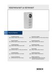
EazeoVideoIntercom.book Page 1 Thursday, December 18, 2003 5:57 PM
VSS7915/00T & VS79155T
Installation Instructions
EN
Eazeo Outdoor Video Intercom
Instruções de Instalação
PT
Manual d’installation
FR
Boîtier intercom vidéo d’extérieur Eazeo
Installationsinstruktioner
DA
Installationshandbuch
DE
Eazeo Außen-Video-Intercom-Box
Interfono Eazeo con vídeo para exteriores
Eazeo-videointercom voor buiten
Videocitofono per esterni Eazeo
Eazeo Outdoor Video Intercom
Installeringsinstruksjoner
NO
Eazeo utendørs videointercom
Οδηγίες εγκατάστασης
Istruzioni sull’installazione
IT
Eazeo Outdoor Video Intercom
Asennusohjeet
SU
Installatiehandleiding
NL
Eazeo udendørs video intercom
Installationsanvisningar
SV
Manual de instalación
ES
Intercomunicador com Vídeo Exterior Eazeo
GR
Σύστηµα βίντεο ενδοεπικοινωνίας
Eazeo για εξωτερικούς χώρους
EazeoVideoIntercom.book Page 1 Thursday, December 18, 2003 5:57 PM
VSS7915/00T & VS79155T | Installation Instructions
EN | 1
IMPORTANT SAFEGUARDS
1.
2.
3.
4.
5.
6.
7.
8.
9.
10.
11.
12.
13.
Read these instructions.
Keep these instructions.
Heed all warnings.
Follow all instructions.
Do not use this apparatus near water.
Clean only with dry cloth.
Install in accordance with the manufacturer’s instructions.
Do not install near any heat sources such as radiators, heat
registers, stoves, or other apparatus (including amplifiers) that
produce heat.
Only use attachments/accessories specified by the manufacturer.
Refer all servicing to qualified service personnel. Servicing is
required when the apparatus has been damaged in any way, such
as power-supply cord or plug is damaged, liquid has been spilled
or objects have fallen into the apparatus, the apparatus has been
exposed to rain or moisture, does not operate normally, or has
been dropped.
The apparatus shall not be exposed to dripping or splashing.
Do not attempt to service this product yourself as removing
covers expose you to dangerous voltage or other hazards.
Upon completion of any service or repairs to this product, ask the
service technician to perform safety checks to determine that the
product is in proper operating condition.
Installation Instructions
ENGLISH
EN
Warning
To reduce the risk of fire or electric shock, this apparatus should not be
exposed to rain or moisture and objects filled with liquids, such as
vases, should not be placed on this apparatus.
Bosch Security Systems | 2003-11
EazeoVideoIntercom.book Page 2 Thursday, December 18, 2003 5:57 PM
VSS7915/00T & VS79155T | Installation Instructions
EN | 2
FCC INFORMATION
This equipment has been tested and found to comply with the limits
for a Class B digital device, pursuant to Part 15 of the FCC Rules.
These limits are designed to provide reasonable protection against
harmful interference in a residential installation. This equipment
generates, uses and can radiate radio frequency energy and, if not
installed and used in accordance with the instructions, may cause
harmful interference to radio communications. However, there is no
guarantee that interference will not occur in particular installation. If
this equipment does cause harmful interference to radio or television
reception, which can be determined by turning the equipment off and
on, the user is encouraged to try to correct the interference by one or
more of the following measures:
• Reorient or relocate the receiving antenna.
• Increase the separation between the equipment and receiver.
• Connect the equipment into and outlet on a circuit different form
that to which the receiver is connected.
• Consult the dealer or an experienced radio/ TV technician for
help.
Warning
Installation should be performed by qualified service personnel only in
accordance with the national electrical code or applicable local codes.
Bosch Security Systems | 2003-11
EazeoVideoIntercom.book Page 3 Thursday, December 18, 2003 5:57 PM
VSS7915/00T & VS79155T | Installation Instructions
EN | 3
1. Introduction
This Eazeo Outdoor Video Intercom is designed for use with Bosch
Color Observation Systems only. This intercom incorporates a high
quality color camera for visual identification of visitors, a tri-color
status indicator and two-way voice communications.
2. Standard package includes
•
•
•
•
•
•
•
•
•
Eazeo Outdoor Video Intercom unit
Mounting box
Frame plate (template)
Raised-mounting surround
Protective dome
Alarm/Action box
Two dual twisted-pair cables - 15 metres / 45ft
These installation instructions
Accessory bag
• A tamper-resistant screw 3 x 10mm
• Security screwdriver
• Metal grommet with lock nut
• Rubber grommet
• Four tamper-resistant screws 4 x 50mm with clips
• Four 3.5 x 25mm screws with plugs
• Four short screws
• A cable connector
• A name plate assembly
Bosch Security Systems | 2003-11
EazeoVideoIntercom.book Page 4 Thursday, December 18, 2003 5:57 PM
VSS7915/00T & VS79155T | Installation Instructions
EN | 4
3. Installation
To obtain the best results from your new Eazeo Outdoor Video
Intercom, read these instructions carefully before use. Retain the
manual for future reference.
This manual describes the installation of the Eazeo Outdoor Video
Intercom. For more detailed information about the installation and
operation of the system monitor you should consult the monitor
manuals.
Remark: When the system configuration is altered, the system
monitor needs to check and memorise the cameras and accessories
connected to its inputs. This is done automatically when the mains
power is switched on (rear switch).
Position
First you need to determine where the intercom is to be installed. The
image sensors in modern CCD cameras are highly sensitive and
require special care for proper performance and extended lifetime.
Please follow the guidelines to get optimum results of your camera:
• Do not expose to direct sunlight or bright spotlights in operating
and non-operating conditions.
• Avoid bright lights in the field of view of the camera.
These bright lights cause a smearing effect, which is visible as white
lines above and below the highlight. Bright lights may cause
bleaching of the sensor's color filters. This will be visible as colored
spots in the picture and is irreversible.
Mounting the unit
Choose from the available mounting methods:
• Sunken mount
• Raised mount
Bosch Security Systems | 2003-11
EazeoVideoIntercom.book Page 5 Thursday, December 18, 2003 5:57 PM
VSS7915/00T & VS79155T | Installation Instructions
EN | 5
Sunken mount
Four tamper-resistant
screws 4 x 50mm with clips
Four short screws
Mounting box
Frame plate
Tamper-resistant screw 3 x 10mm
•
•
•
Using the inside of the frame plate as a template, mark the
position of the hole required for the unit.
Cut out the center hole.
Use the four tamper-resistant screws (4 x 50mm) and clips to attach
the frame plate to the surface (use the outer holes).
• If you want to mount the mounting box directly onto a wall
instead, break out the four tabs in the mounting box and drill
holes for the four 3.5 x 25mm screws (use plugs if necessary).
Bosch Security Systems | 2003-11
EazeoVideoIntercom.book Page 6 Thursday, December 18, 2003 5:57 PM
VSS7915/00T & VS79155T | Installation Instructions
•
•
•
•
•
•
EN | 6
Identify the top of the mounting box (the tamper-resistant screw
thread is at the bottom).
Decide which rear entry hole (big or small) you will use for the
cable and break out the corresponding tab in the mounting box.
Mount the metal grommet supplied (if you have chosen the
smaller rear entry point use the rubber grommet supplied).
Run the connection cable through the grommet leaving about
15cm sticking out and tighten the metal grommet.
Using the four short screws attach the mounting box to the frame
plate.
Crimp the supplied connector onto the cable (see section System
Cable).
Raised mount
Top recess
Four 3.5 x 25mm
screws with plugs
Bosch Security Systems | 2003-11
Raised-mounting
surround
EazeoVideoIntercom.book Page 7 Thursday, December 18, 2003 5:57 PM
VSS7915/00T & VS79155T | Installation Instructions
•
•
•
•
•
•
•
•
EN | 7
Identify the top of the mounting box and the top of the raisedmounting surround (the top cable entry hole is offset to the right).
Decide the entry point (top, bottom or rear) for the cable and
break out the corresponding tabs in the mounting box and (if
required) the raised-mounting surround.
Break out the four screw holes in the rear of the mounting box
and use these holes to mark the position for drilling the surface.
Fit the mounting box into the raised-mounting surround.
Mount the grommet.
Run the connection cable through the grommet leaving about
15cm sticking out (if you enter from the top leave 20cm) and
tighten the grommet.
Use the four 3.5 x 25mm screws (with plugs if necessary) to attach
these two units to the surface.
Crimp the supplied connector onto the cable (see section System
Cable).
Attaching the intercom unit
The intercom unit is now ready to be fitted to the mounting box.
• Connect the cable to the unit.
• Clip the top of the unit into the top recesses of the mounting box.
• Use a finger to fold the cable back along the side of its connector
to the center of the printed circuit board. (If the cable enters from
the top make sure that it is first firmly secured in the cable guide
of the mounting box.)
• Lower the unit into place and secure underneath with the
3 x 10mm tamper-resistant screw.
• If necessary (and without touching the lens), adjust the camera
position (check the picture on the screen).
• The protective dome cannot be removed afterwards, so ensure
that you are completely satisfied with the camera position before
you click the dome into place.
• Fill-in the name card and click into place with its transparent
cover.
Bosch Security Systems | 2003-11
EazeoVideoIntercom.book Page 8 Thursday, December 18, 2003 5:57 PM
VSS7915/00T & VS79155T | Installation Instructions
EN | 8
System Cable
For the interconnections between the system monitor and the Eazeo
Outdoor Video Intercom, a 15m/45ft system cable is supplied. For
optimum picture quality, always use a 4-wire dual twisted-pair cable
when extending the connection. The maximum cable length allowed
is 200m/600ft. Ensure that the connectors are fixed to the cable as
shown in the figure.
2 34 5
2 34 5
2
3
2
3
45
4-5
2-3
45
4-5
2-3
CAUTION:
The plugs used for the observation system have the same
dimensions as standard telephone plugs. Never connect a
telephone to the Eazeo Outdoor Video Intercom or system
monitor.
Bosch Security Systems | 2003-11
EazeoVideoIntercom.book Page 9 Thursday, December 18, 2003 5:57 PM
VSS7915/00T & VS79155T | Installation Instructions
EN | 9
Adjustments and switches
The printed circuit board has an loudspeaker level potentiometer,
two DIP switches and an anti-tamper alarm switch.
Loudspeaker
level
adjustment
DIP 1
default Off
DIP 2
Anti-tamper
override switch
(default Off)
Anti-tamper
switch
Anti-tamper switch override
When the unit is removed from the mounting box the anti-tamper
switch triggers an alarm on the monitor. To suppress this alarm while
servicing the system, set the tamper override DIP switch to the On
position. Don’t forget to reactivate the anti-tamper switch by
switching the override to the Off position.
Bosch Security Systems | 2003-11
EazeoVideoIntercom.book Page 10 Thursday, December 18, 2003 5:57 PM
VSS7915/00T & VS79155T | Installation Instructions
EN | 10
Focus
The built-in lens provides an optimal image sharpness for objects
between 0.25m / 0.82ft and infinity (depth of field). The focus is
preset. No further adjustment is required.
Operation
When the Eazeo Outdoor Video Intercom is connected to the Eazeo
Observation System and the system is switched on, the intercom
image appears on the monitor screen. If necessary adjust contrast,
brightness and color (see the View Settings menu of the monitor) to
optimize the image on the system monitor.
When the indicator light on the intercom is green, the intercom is in
the ready mode.
The button on the intercom is used as call bell. When pushed, the
buzzer in the monitor and in the intercom sounds. The monitor
switches to the intercom camera input. The indicator light on the
intercom is orange - the visitor can talk. The system monitor
reproduces the sound received from the intercom.
To talk back to your visitor push TALK. The indicator light on the
intercom is red. The system monitor does not receive sound from the
intercom when the red light is on. The sound received by the system
monitor’s microphone is reproduced by the intercom.
If you don’t react within 3 minutes then the monitor returns to its
previous status (for example, the automatic camera sequence
continues).
Bosch Security Systems | 2003-11
EazeoVideoIntercom.book Page 11 Thursday, December 18, 2003 5:57 PM
VSS7915/00T & VS79155T | Installation Instructions
EN | 11
4. Tips for maintenance
Cleaning
You can clean the outside of the Outdoor Video Intercom unit with a
moist fluff-free cloth or shammy leather cloth.
When cleaning the camera lens a special cleaning cloth should be
used. Do NOT use cleaning fluids based on alcohol, methylated
spirit, ammonia, etc.
Never touch the glass of the camera lens to prevent damaging its
delicate coating.
Avoid direct contact with water.
5. Specifications
VSS7915/00T
VS79155T
PAL
NTSC
Integrated lens
Integrated lens
Accessories
The following accessories are available:
• Extension system cables (loop resistance max. 16 Ω at 100m).
• Cable extension box for providing additional power and cable
length compensation to the Eazeo Outdoor Video Intercom at
longer distances (up to 300m / 900ft).
Electro Magnetic Compatibility (EMC)
This equipment complies with the European EMC directive used
standards:
EN50130-4, EN55022
USA standard: FCC part 15, class B
Australia AS/NZS 3548
Safety
according to European standard EN60065 ; USA UL6500
Bosch Security Systems | 2003-11
EazeoVideoIntercom.book Page 12 Thursday, December 18, 2003 5:57 PM
VSS7915/00T & VS79155T | Installation Instructions
EN | 12
Environmental conditions
Operating temperature
Non operating temperature
Relative humidity Non-condensing
-20ºC +50ºC (-4ºF +122ºF)
-25ºC +70ºC (-13ºF +158ºF)
0% to 95% RH
Input Voltage, via tp-input:
Power consumption
Weight
Dimensions
24VDC
< 3.5W
0.51 kg / 1.12 lbs
80 x 163 x 65 mm (WxHxD)
3.1 x 6.4 x 2.5 ins (WxHxD)
If you have any problems, contact your dealer.
Bosch Security Systems | 2003-11