1
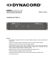
SbA750 User Manual Electro-Voice® SbA750 User Manual Important Safety Instructions The lightning flash with arrowhead symbol, within an equilateral triangle is intended to alert the user to the presence of uninsulated dangerous voltage within the products enclosure that may be of sufficient magnitude to constitute a risk of electric shock to persons. The exclamation point within an equilateral triangle is intended to alert the user to the presence of important operating and maintenance (servicing) instructions in the literature accompanying the appliance. 1. Read these instructions. 2. Keep these instructions. 3. Heed all warnings. 4. Follow all instructions. 5. Do not use this apparatus near water. Do not expose this apparatus to dripping or splashing and ensure that no objects filled with liquids, such as vases, are placed on this apparatus. 6. Clean only with a dry cloth. 7. Do not block any of the ventilation openings. Install in accordance with the manufacturers instructions. 8. Do not install near any heat sources such as radiators, heat registers, stoves, or other apparatus (including amplifiers) that produce heat. 9. Only use attachments/accessories specified by the manufacturer. 10. Refer all servicing to qualified service personnel. Servicing is required when the apparatus has been damaged in any way, such as power-supply cord or plug is damaged, liquid has been spilled or objects have fallen into the apparatus, the apparatus has been exposed to rain or moisture, does not operate normally, or has been dropped. 11.To completely disconnect AC power from this apparatus, the power supply cord must be unplugged. For US and CANADA only: Do not defeat the safety purpose of the grounding-type plug. A grounding type plug has two blades and a third grounding prong. The wide blade or the third prong are provided for your safety. When the provided plug does not fit into your outlet, consult an electrican for replacement of the absolete outlet. Important Service Instructions CAUTION: These servicing instructions are for use by qualified personnel only. To reduce the risk of electric shock, do not perform any servicing other than that contained in the Operating Instructions unless you are qualified to do so. Refer all servicing to qualified service personnel. 1. Security regulations as stated in the EN 60065 (VDE 0860 / IEC 65) and the CSA E65 - 94 have to be obeyed when servicing the appliance. 2. Use of a AC separator transformer is mandatory during maintenance while the appliance is opened, needs to be operated and is connected to the AC. 3. Switch off the power before retrofitting any extensions, changing the AC voltage or the output voltage. 4. The minimum distance between parts carrying AC voltage and any accessible metal piece (metal enclosure), respectively between the AC poles has to be 3 mm and needs to be minded at all times. The minimum distance between parts carrying AC voltage and any switches or breakers that are not connected to the AC (secondary parts) has to be 6 mm and needs to be minded at all times. 5. Replacing special components that are marked in the circuit diagram using the security symbol (Note) is only permissible when using original parts. 6. Altering the circuitry without prior consent or advice is not legitimate. 7. Any work security regulations that are applicable at the location where the appliance is being serviced have to be strictly obeyed. This applies also to any regulations about the work place itself. 8. All instructions concerning the handling of MOS - circuits have to be observed. Electro-Voice® SbA750 User Manual Table of Contents 0 Introduction .............................................................................................................................................................. 1 Unpacking and Warranty ............................................................................................................................... 1 Setup and Connections ................................................................................................................................. 1 1 Quick Start ............................................................................................................................................................... 2 2 Controls ................................................................................................................................................................... 3 Input L/Mono Input R ..................................................................................................................................... 3 Parallel Outputs L/R ....................................................................................................................................... 3 Mid-High Outputs L/R .................................................................................................................................... 3 Level .............................................................................................................................................................. 3 Status Indicators ............................................................................................................................................ 4 Power Switch ................................................................................................................................................. 4 AC Fuse ........................................................................................................................................................ 4 AC Connector ................................................................................................................................................ 4 3 Cabling .................................................................................................................................................................... 5 4 Setup Example A ..................................................................................................................................................... 6 5 Setup Example B ..................................................................................................................................................... 7 6 Setup Example C ..................................................................................................................................................... 8 7 Setup Example D ..................................................................................................................................................... 9 8 Setup Example E ................................................................................................................................................... 10 9 Specifications ......................................................................................................................................................... 11 10 Dimensions ........................................................................................................................................................... 11 11 Block Diagram ..................................................................................................................................................... 12 Electro-Voice® SbA750 User Manual TOC 0. Introduction Congratulations! In buying an Electro-Voice® SbA750 you decided on getting one of todays most advanced active subwoofers incorporating sophisticated technology. The active 15" subwoofer SbA750 with integrated 750 watt power amplifier has been specially designed to provide fundamental bass support for professional full-range and multi-channel cabinets. Through the integrated electronic frequency crossover of the SbA750 setting up an active stereo multi-channel system is truly simple. The stereo audio signals for the mid-high range cabinets are provided via the MID-HIGH outputs on the SbA750. Additionally provided are all connection facilities for using the SbA750 as active mono subwoofer in active 2-way or add-on operation. Manufactured from baltic birch and housing a highperformance Electro-Voice® DL15Y woofer, the SbA750 withstands even the hardest strain during transport and operation. While input connection is also possible via phone type jacks, all input and output signals are output via professional XLR-type connectors. The integrated High-Efficiency 750W power amplifier optimally matches the DL15Y woofer offering highest dynamic and audio performance and ensures at the same time that the DL15Y woofer is always operated in its optimum operation range. Extensive protection circuitry like VCP, DC/HF-protection, audio limiter, Back-EMF protection and thermal protection are employed to securely monitor the compliance to these operation limits guaranteeing that the SbA750 provides outstanding performance even under most demanding conditions. The SbA750 is also especially suitable for many rental applications. Compared to Class-AB-operated amps and because of utilizing Class-H HighEfficiency technology the power amplifier produces significantly less power loss, and additionally reduces thermal stress of all components. Employing fans to ensure thermal stability is not necessary because of the Class-H technology and use of comprehensively dimensioned cooling profiles. The enclosure is sealed with extremely durable Futura coating and a robust powder-coated steel grille provides protection for the Electro-Voice® DL15Y woofer against mechanical damage. All controls and the cooling profiles of the power amp module are recessed to provide optimum protection for the sensitive parts of the SbA750 even during transportation. Two carrying handles, four castors and an integrated threaded pole-mount stand flange allow comfortable transportation and optimum, space saving installation. Because of its versatility, the SbA750 can be easily integrated into any existing sound reinforcement installation. Unpacking and Warranty Open the packing and carefully take out the SbA750. Remove the protective foil from the carrying handles. A power cord and the warranty card are supplied in addition to this owners manual. Please make sure that all details are filled in on the warranty card. Only a completely filled in warranty certificate entitles you to stake any warranty claims. Therefore, keep the original invoice together with the warranty certificate at a safe place. Setup and Connections Place the SbA750 on an even ground if possibly by using the supplied rubber feet to ensure safe operation. Make sure to check the stability of the system when using pole-mount stands. Do not cover the heat sink on the subwoofers rear during operation. Otherwise, the SbA750 will enter protection mode because of thermal overload. Although this provides reliable protection for the subwoofer, sound reproduction is muted until the normal operation mode is regained. AC power is supplied via the Neutriks professional PowerCon connector system and by use of an 15 (5m) AC cord. This ensures an absolute secure and reliable power supply connection. However, with large installations consisting of several active cabinets, the use of high-quality AC distributors that allow high power consumption and offer reliable protection throughout the entire system is strongly recommended. Before establishing the AC connection for the first time, make sure that the SbA750s operation voltage setting, which can be found on a label next to the AC switch, corresponds to your local AC voltage. 1 Electro-Voice® SbA750 User Manual 1. Quick Start Caution: Before switching on the power of the SbA750 always set the LEVEL control to its counterclockwise stop. A playing sound source could otherwise lead to extreme output levels. This Quick Start Manual outlines the set up and operation of a SbA750 used as add-on subwoofer together with a Powermixer (see configuration examples). The operation procedures are equivalent for other mixers. 1. Set up your Powermixer system as usual and connect a signal source to the power mixer (e.g. CD Player or microphone). 2. Place your SbA750 somewhere between your full-range cabinets. 3. Set the SbA750s LEVEL control to its counterclockwise stop and connect the unit to a wall outlet using the supplied PowerCon mains cord. 4. Use a stereo phone plug cable to connect the Powermixers MONO OUT to the SbA750s L/MONO INPUT. 5. Move the Mixer MONO OUT fader all the way down. 6. Be sure to switch on the Mixer first and then the SbA750. Switching on the SbA750 last is recommended. Otherwise, unwanted power-on noise might occur. When switching off your equipment, please proceed in the opposite order, i.e. switch off the SbA750 first. 7. Set the SbA750s LEVEL control to its center position (0dB) and start the playback of the desired signal audio source. 8. After adjusting the desired acoustic output level of the full-range cabinets using the Powermixers master fader, establish volume setting for the subwoofer using the MONO OUT fader. Electro-Voice® SbA750 User Manual 2 2. Controls Input L/Mono, Input R Electronically balanced inputs for the connection of highlevel signal sources such as mixers, signal processors, etc. Establishing the connection is possible via phone or XLR-type jacks. Balanced connection is recommended to prevent noise or HF-interference. Caution: Before connecting or disconnecting any plugs, make sure to set the level control to its counterclockwise stop, which prevents the system, the audience and yourself from being stressed by nasty contact noise. The input section of the SbA750 also allows mono sub operation. The stereo signal is fed to the L and R inputs and the low-frequency range signals of both channels are summed prior to being processed in the power amplifier section. All other applications use only the (L)/Mono input. Please also refer to the chapter SETUP EXAMPLES. Parallel Outputs L/R Parallel connected to the main inputs these sockets are used for carrying through the input signals. Mid-High Outputs L/R The input signal is split via the integrated electronic crossover (PowerMax, 100Hz). Low-frequency signals are routed to the internal power amplifier of the SbA750 while high-frequency signals are present at the Mid-High outputs for further distribution to external power amps or active mid-high range cabinets. Level This control sets the output volume of the SbA750 in a range between -∞dB and +10dB. The internal power amplifier provides a nominal input sensitivity of +6dBu. 3 Electro-Voice® SbA750 User Manual Status Indicators These indicators provide information about the actual operational state of the SbA750s internal power amplifier. Signal Indicates that an audio signal is present at the input and that it is output. Limit When lit this indicator signals that the internal power amplifier actually operated at the threshold of clipping. Short-term blinking is not critical, because the amps audio limiter keeps distortion under control, so that the sound is unaffected. Input overdrive, which results in sound degradation, is a probable cause for a continuously lit indicator. To prevent this from happening, reduce the input level. VCP Lights when the power amplifiers Voice-Coil-Protection is activated. During dynamic peaks the integrated power amplifier is capable of producing output levels that exceed its stated nominal output capacity. Therefore, the SbA750 employs a VCP circuit (Voice-Coil-Protection), which simulates the thermal behavior of the speakers voice-coil, automatically reducing the energy fed to the speaker system on the occurrence of thermal overload. Protect Lights when one of the multiple comprehensive protections, e.g. against thermal overload, HF, DC or Back-EMF of the power amplifier is activated. Preventing the woofer from being damaged, it is shutoff via relays in the protect mode. Additionally, the input level is being reduced. During power-on the PROTECT LED lights for approximately 2 seconds, which is normal. This only indicates that all protection circuitry has been activated properly. Power Switch AC switch for switching the SbA750s power ON or OFF. The switch lights after turning the power ON. Make sure that the AC cord is correctly connected if the switch is not lit upon turning the power on. If the AC cord is correctly connected and the AC switch does not light upon power-on, please contact your local dealer. AC Fuse During normal operation the AC fuse of the SbA750 only blows at the occurrence of a malfunction. Exchanging the fuse is only permissible using a fuse of the same type (current, voltage and release characteristic). In case the fuse blows frequently, please contact your local dealer. AC Connector AC connection is established via a PowerCon connector. A 15 (5m) long AC cord with PowerCon plug is supplied. CAUTION: THIS APPLIANCE HAS NO USER-SERVICABLE PARTS INSIDE. LEAVE ANY SERVICING AND MAINTENANCE QUALIFIED SERVICE TECHNICIANS ONLY. Electro-Voice® SbA750 User Manual 4 3. Cabling LF-Cords Using balanced cables with phone or XLR-type plugs for connecting signal sources to the SbA750 is strongly recommended to prevent problems caused by noise interference. Make sure to mind the pin-assignment as shown below. 2, SIGNAL + XLR MALE XLR FEMALE 3, SIGNAL - 3, SIGNAL - 2, SIGNAL + SIGNAL SIGNAL + SIGNAL + The following illustration shows the most important cable connections and their pin-assignment. A balanced wiring is to be preferred in each case. Standard XLR-Cable signal + signal - Cable connection phone to XLR-type, unbalanced signal + signal - Cable connection phone to XLR-type, balanced signal + signal - Standard phone-type, unbalanced signal + signal - Standard phone-type, balanced signal + 5 signal - Electro-Voice® SbA750 User Manual 4. Setup Example A Add-On Operation The easiest way to expand your power mixer by means of a SbA750. Electro-Voice® SbA750 User Manual 6 5. Setup Example B Stereo 2-way Active Operation with Mono Subwoofer In this operation mode only the Mid/High signals are fed to the fullrange speaker cabinets, which allows higher acoustic output levels. 7 Electro-Voice® SbA750 User Manual 6. Setup Example C Stereo 2-way Active Operation with Stereo Subwoofer The second SbA750 provides improved SPL in the bass range, in a full Stereo Setup. Electro-Voice® SbA750 User Manual 8 7. Setup Example D Stereo 2-way Active PA-System Using two SbA750s to expand an existing fullrange-system, in a full Stereo Setup. 9 Electro-Voice® SbA750 User Manual 8. Setup Example E PA-system with Active Components SbA750 in combination with the SxA250, or other active cabinets. SxA 250 Electro-Voice® SbA750 User Manual SxA 250 10 9. Specifications Freq. Range (-10 dB): 45 Hz - 150 Hz Amplifier Design: Hi-Efficiency Class H Output Power : 750W (RMS) Sensitivity (SPL 1W/1m): 100 dB Max Calculated SPL: 128 dB Components: EV DL15Y Connectors: 2 XLR/Jack Combo Input 2 XLR Slave Through 2 XLR Mid-Hi Output Level Control: +40 dB to -10 dB Internal Crossover : PowerMax 12, 100 Hz Cooling: Convection Cooled, Passive Protection: Dynamic Limiter, DC, HF High Temperature, Peak Current Limiter Power Requirements: 100V, 120V, 230V, 240V Cabinet: 18mm Baltic Birch Vented Enclosure, 4 Wheels, Pole Mount (M20), 2 Handles Cabinet Finish: Futura Grille: Black Powder-Coated Steel Dimensions 23.7" x 16.9" x 22.0"/26.2" (H x W x D/D w/Wheels): (603mm x 428mm x 558/665mm) Net Weight: 94.7 lbs (43 kg) 10. Dimensions 11 Electro-Voice® SbA750 User Manual 11. Block Diagram Electro-Voice® SbA750 User Manual 12 U.S.A. and Canada: For customer orders, contact the Customer Service department at: 800/392-3497 Fax: 800/955-6831 For warranty repair or service information, contact the Service Repair Department at: 800/685-2606 For technical assistance, contact Technical Support at: 866/78-AUDIO Specifications subject to change without notice. All Other International Locations: 952-884-4051 Fax: 952-736-4212 www.electrovoice.com l Telex Communications, Inc. l www.telex.com Printed in U.S.A © Telex Communications, Inc. 3/2003 Part Number 38110-235 Rev A Electro-Voice® SbA750 User Manual