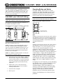
1
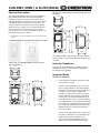
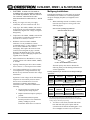
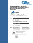
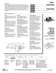
CLW-DIM1, DIMS1, & SLVD1(W/A/B)
Introduction
Features and Functions
The CLW-DIM1 (-DIM1) is a stand-alone wall box
dimmer that can also act as a Cresnet® device that reports
to a Crestron® control processor. The CLW-DIM1 has
two preset lighting levels that can be adjusted (refer to
note below). The CLW-DIM1 also includes two isolated,
non-polarized Cresnet wires (plus a ground wire) for
connecting to the Cresnet network over a twisted pair
wire with shield.
Specifications
Following are specifications for the -DIM1, -DIMS1, and
-SLVD1.
CLW-DIM1, CLW-DIMS1, & CLS-SLVD1 Specifications
SPECIFICATION
DETAILS
Power Requirements
Line Power, 120 VAC, 60 Hz
Default Net ID
-DIM1: 80
-DIMS1: 81
Switch Type
Dimmer
NOTE: The two preset levels are noted as Preset 1-High
and Preset 1- Low. “Preset 1-High” is usually used for
turning lights on to full brightness while preset “Preset 1Low” is usually used for turning the lights off. Although
“Preset 1-High” and “Preset 1-Low” are usually used for
“On” and “Off” respectively, the light level for each
preset can be customized by the user. Refer to “Operating
Button and Switch” on page 5 for more information on
customizing light levels.
Load Type
Incandescent, Tungsten-Halogen,
Magnetic Low Voltage
2-Series Control System
1,2
Update File
Version 3.117 or later
The CLW-DIM1 features a three-position mode selection
switch. Refer to “Operating Button and Switch” on page 5
for more information. In the absence of Cresnet
communications, the dimmer can still be used to control
lighting.
Operating Temperature
and Humidity
32°F to 104°F (0°C to 40°C)
10 to 90% Relative Humidity
(Non-Condensing)
Dimensions and Weight
-DIM1 and -DIMS1:
Height: 4.13 in (10.48 cm)
Width: 2.38 in (6.03 cm)
Depth: 1.91 in (4.85 cm)
Weight: 4.9 oz (0.67 kg)
-SLVD1:
Height: 4.13 in (10.48 cm)
Width: 1.75 in (4.45 cm)
Depth: 1.91 in (4.85 cm)
Weight: 3.6 oz (0.50 kg)
Load Ratings
Incandescent/Tungsten
Halogen
Magnetic Low Voltage
The CLW-DIMS1 (-DIMS1) is similar to the -DIM1 with
the added capability of working with a slave unit
(CLW-SLVD1) in a multi-switch / single circuit
application.
The CLW-SLVD1 (-SLVD1) is a slave unit that when
used in conjunction with the -DIMS1 acts as an additional
dimmer control point in a multi-dimmer / single circuit
application. It does not connect to a Cresnet system and
cannot be used without a -DIMS1. The -SLVD1 does not
have a mode selection switch and is not programmable. It
emulates the operation of the -DIMS1 to which it is
connected.
The -DIM1, -DIMS1, and -SLVD1 are available in white,
almond, and black. White units are designated by part
numbers ending in “W”. Almond units are designated by
part numbers ending in “A”. Black units are designated by
part numbers ending in “B”. Each dimmer can be covered
with a decorative faceplate (not supplied).
Crestron Electronics, Inc.
15 Volvo Drive Rockleigh, NJ 07647
Tel: 888.CRESTRON
Fax: 201.767.7576
www.crestron.com
3
4
-DIM1: 1000W
-DIMS1: 1000W
-SLVD1: N/A
-DIM1: 1000VA/750W
-DIMS1: 1000VA/750W
-SLVD1: N/A
1.
The latest versions can be obtained from the Downloads | Software
Updates section of the Crestron website (www.crestron.com).
Refer to NOTE below.
2.
Crestron 2-Series control systems include the AV2 and PRO2.
Consult the latest Crestron Product Catalog for a complete list of
2-Series control systems.
3.
Refer to Derating Charts for Multigang Installations on page 3.
4.
VA ratings are for input power to the transformer. If you do not
know the input power requirement of the transformer, use the
bulb’s wattage rating to determine proper rating.
NOTE: Crestron software and any files on the website
are for Authorized Crestron dealers and Crestron
Authorized Independent Programmers (CAIP) only. New
users may be required to register to obtain access to
certain areas of the site (including the FTP site).
Installation Guide – DOC. 6250
07.04
Specifications subject to
change without notice.
CLW-DIM1, DIMS1, & SLVD1(W/A/B)
Physical Description
The -DIM1 and -DIMS1 contain one large pushbutton, a
light emitting diode (LED) with software adjustable
brightness*, and a three-position slider-switch, shown
after this paragraph. The -SLVD1 is similar to the -DIM1
and -DIMS1 but does not have the slider-switch. Line
voltage connections are made at the rear of the dimmer.
Three Class 2 low voltage wires, located on the front of
the switch provide a Cresnet connection to a control
system. The wires are routed to the bottom of the unit for
placement outside of the wall box.
*
Physical view of CLW-SLVD1 (clockwise from top; Top, Side,
and Front)
1.91 in
(4.85 cm)
1.75 in
(4.45 cm)
LED brightness can only be adjusted through Crestron programming
software.
3.81 in
(9.68 cm)
3.28 in
(8.32 cm)
CLW-DIM1/-DIMS1 (L) and CLW-SLVD1 (R) shown in white
2.70 in
(6.86 cm)
4.13 in
(10.48 cm)
1.50 in
(3.81 cm)
The -DIM1, -DIMS1, and -SLVD1 mount in a standard
wallbox and are covered using a decorative faceplate (not
included).
Physical view of CLW-DIM1/-DIMS1 (clockwise from top;
Top, Side, and Front)
Industry Compliance
This unit has been manufactured to comply with UL’s
Standards for Safety in Canada and the United States.
Formal approval is pending.
1.75 in
(4.45 cm)
Important Notes
Read before installation.
2.38 in
(6.03 cm)
•
1.91 in
(4.85 cm)
3.81 in
(9.68 cm)
3.28 in
(8.32 cm)
2.70 in
(6.86 cm)
4.13 in
(10.48 cm)
1.50 in
(3.81 cm)
Codes: Install in accordance with all local and
national electrical codes.
Alternate wiring methods may be used for the
Class 2 wiring connection. The 2002 National
Electrical Code (Article 725-55) prohibits Class
2 conductors of the -DIM1, -DIMS1, and
-SLVD1 to occupy the same outlet box as the
power conductors. The exception is Part D of
Section 725.55 of the 2002 National Electrical
Code, which allows a device’s power conductors
to be installed near (0.25 inch minimum spacing)
associated Class 2 conductors in the same outlet
box. Consult the 2002 National Electrical Code
Handbook and your local electrical inspector
before proceeding.
Do not use the supplied butt-splice connectors if
the Class 2 conductors are to be installed in the
wallbox with the power conductors. Use
approved connectors (supplied by others) to
make Class 2 connections inside the wallbox.
2 • Stand Alone Wall Box Dimmer : CLW-DIM1, DIMS1, & SLVD1
Installation Guide – DOC. 6250
CLW-DIM1, DIMS1, & SLVD1(W/A/B)
•
CAUTION: TO REDUCE THE RISK OF
OVERHEATING AND POSSIBLE DAMAGE
TO OTHER EQUIPMENT, DO NOT INSTALL
TO CONTROL A RECEPTACLE OR A
MOTOR OPERATED APPLIANCE (i.e. BATH
FAN).
Multigang Installations
In multigang installations, several controls are grouped
horizontally in one wallbox. For a smooth appearance,
one-piece multigang faceplates (not supplied) can be
installed.
1.
•
Wiring: Use copper wire only. For supply
connections, use wires rated for at least 75°C.
•
Lamp Type: The -DIM1, -DIMS1, and -SLVD1
are designed for use with permanently installed
incandescent, magnetic low voltage, or tungstenhalogen only.
•
Temperature: The -DIM1, -DIMS1, and -SLVD1
are designed to be used where temperatures are
between 32° to 104°F (0° to 40°C).
•
Wallboxes: Devices mount in standard
wallboxes. For easy installation, Crestron
recommends using 3 ½” deep wallboxes. Several
devices can be installed in one wall box
(multigang). This requires the removal of side
sections (refer to diagram on page 3) and the
derating of the dimming device. For a smooth
appearance, one-piece multigang faceplates (not
supplied) can be installed.
•
Other Switch Devices: Mechanical 3- or 4-way
switches will not work with the -DIM1, -DIMS1,
or -SLVD1.
•
Spacing: If mounting one device above another,
leave at least 4 ½” vertical space between them.
•
Low Voltage Applications: Use with core and
coil (magnetic) low voltage transformers only.
Do not use any solid-state electronic low voltage
transformers.
Operation of a low voltage circuit with all lamps
inoperative or removed may result in current
flow in excess of normal levels. To avoid
transformer overheating and premature
transformer failure, Crestron recommends the
following:
Inner Sections of Multiganged Switches
REMOVE INNER SECTIONS
DO NOT REMOVE OUTER SECTIONS
The load capacity must also be derated. The
following charts provide derating information for
various applications.
Derating Information for Incandescent and Tungsten Halogen
Applications
Part
Number
One Side
Removed
Two Sides
Removed
-DIM1
1000W
600W
400W
-DIMS1
1000W
600W
400W
No Derating Necessary
Derating Information for Magnetic Low Voltage Applications*
Part
Number
Replace burned-out lamps as quickly as
possible.
Installation Guide – DOC. 6250
No Side
Removed
-SLVD1
Do not operate low voltage circuits
without operative lamps in place.
Use transformers that incorporate
thermal protection or fuse transformer
primary windings to prevent
transformer failure due to overcurrent.
When combining controls in a wallbox, remove
inner side sections prior to wiring (refer to the
following figure).
One Side
Removed
Two Sides
Removed
-DIM1
1000VA/750W
600VA/450W
400VA/300W
-DIMS1
1000VA/750W
600VA/450W
400VA/300W
-SLVD1
*
No Side
Removed
No Derating Necessary
VA ratings are for input power to the transformer. If you do not
know the input power requirement of the transformer, use the bulb’s
wattage rating to determine proper rating.
2.
To remove a side section, bend the side section
back and forth with a pair of pliers until the
section breaks off from the mounting plate. Use a
file or sandpaper to remove any excess metal.
Stand Alone Wall Box Dimmer: CLW-DIM1, DIMS1, & SLVD1 • 3
CLW-DIM1, DIMS1, & SLVD1(W/A/B)
Prewire for Master Application
Each device has two Class 2 low voltage wires (plus a
ground wire) that provide a Cresnet connection over
shielded twisted-pair to a Crestron control system. These
wires are routed to the bottom of the device for
connection outside of the wallbox. The low voltage wires
are pulled from each device location to the Crestron
control system or a Crestron connection block device. Use
#22 AWG, twisted, shielded, 2-conductor wire. Wiring
can be daisy chained, T-tapped, or home run back to the
control system. Refer to the following wiring diagram.
longer present. The warranty is void if the -DIM1,
-DIMS1, or -SLVD1 is installed and operated with a
shorted load.
1.
Turn power off at the circuit breaker.
2.
If installing multiple dimmers (-DIM1 or
-DIMS1), note the serial number on each device
and make sure they are being installed in the
proper location.
3.
Pull Class 2 low voltage wires through a hole in
the drywall located outside of the electrical box,
to the Crestron control system or a Crestron
connection block device. Leave wires outside of
the wallbox for connection to the -DIM1 or DIMS1.
Wiring Diagram of CLW device to Cresnet
NOTE: Alternate wiring methods may be used for the
Class 2 wiring connection. Refer to section 725-55, Part
D of the 2002 National Electric Code.
4.
NOTE: The GRAY (Cresnet) wires are not polarized.
These wires can be connected to either the Y or Z line on
a Cresnet port.
NOTE: The BLACK wire (Cresnet ground) should not
be grounded with the GREEN (Ground) wire on the
-DIM1/-DIMS1.
NOTE: Crestron recommends using Cresnet-DM cable
for connecting the -DIM1 and -DIMS1 to the Cresnet
network.
Wire the device for the appropriate application.
Choose either “CLW-DIM1 / CLW-DIMS1
Wiring” or “CLW-DIMS1 with CLW-SLVD1
Wiring”, shown on this page and the following
page.
NOTE: Alternative wiring methods can be obtained from
the Dealer/Tech Resources | Design Center section of the
Crestron website (http://www.crestron.com/dealertech_resources/design_center/hot_design_tips_and_
diagrams/tech_sales_tips/).
CLW-DIM1 / CLW-DIMS1 Wiring
Installation
NOTE: The -DIM1 and -DIMS1 require a neutral wire
for operation. If no neutral is present, contact a licensed
electrician for installation or contact Crestron customer
service for alternative wiring options.
NOTE: The -DIMS1 must be installed in the same
wallbox that contains the connections to the load.
The following wiring diagram illustrates installation of
the -DIM1 or -DIMS1.
NOTE: The -DIM1, -DIMS1, and -SLVD1 require a
neutral wire for operation. If no neutral is present, contact
a licensed electrician for installation or contact Crestron
Customer Service for alternative wiring options.
Wiring Diagram for CLW-DIM1 (L) or CLW-DIMS1 (R)
WARNING: Turn off power at the circuit breaker.
Installing with power on can result in serious personal
injury and damage to the device.
NOTE: New installations should be checked for short
circuits prior to installing the -DIM1, -DIMS1, or
-SLVD1. With power off, close the circuit and restore
power. If the lights do not work or a breaker trips, check
and correct the wiring or fixture (if necessary). Install the
-DIM1, -DIMS1, or -SLVD1 only when the short is no
Hot
Hot
BLUE
BLACK
RED
BLACK
RED
LINE
120VAC
60Hz
LINE
120VAC
60Hz
Load
WHITE
GREEN
Cresnet
Neutral
4 • Stand Alone Wall Box Dimmer : CLW-DIM1, DIMS1, & SLVD1
Load
GREEN
WHITE
Ground
Cresnet
Ground
Neutral
Installation Guide – DOC. 6250
CLW-DIM1, DIMS1, & SLVD1(W/A/B)
NOTE: The RED (Load) and BLACK (Hot) wires are
#14 AWG. The BLUE (Slave) and WHITE (Neutral)
wires are #18 AWG. The GREEN (Ground) wire is #16
AWG. The GRAY (Cresnet) wires are #22 AWG. The
BLACK wire (Cresnet ground) paired with the GRAY
(Cresnet) wires is #22 AWG.
Operating Button and Switch
The -DIM1, -DIMS1, and -SLVD1 have one large
pushbutton. The -DIM1 and -DIMS1 also have a threeposition mode selection switch. The function of the
pushbutton is determined by the position of the mode
selection switch. Refer to the following diagram.
CLW-DIMS1 with CLW-SLVD1 Wiring
NOTE: The -SLVD1 does not have a mode selection
switch. It will act in the same mode as the -DIMS1.
NOTE: The -DIMS1 must be installed in the same
wallbox that contains the connections to the load.
Buttons of CLW-DIM1, -DIMS1, and -SLVD1
The following wiring diagram illustrates installation of
the -DIMS1 with multiple -SLVD1s.
Wiring Diagram of CLW-DIMS1 with multiple CLW-SLVD1s
CLW-SLVD1
CLW-SLVD1
Button
CLW-DIMS1
Hot
BLACK
BLUE
BLACK
BLUE
BLUE
BLACK
Mode Selection Switch
(-DIM1 & -DIMS1 Only)
RED
LINE
120VAC
60Hz
Load
WHITE
GREEN
WHITE
Ground
GREEN
Ground
GREEN
WHITE
Cresnet
Ground
Neutral
NOTE: Do not connect the BLUE (Slave) wire to the
Black (Hot) or RED (Load) wires.
NOTE: The RED (Load) and BLACK (Hot) wires are
#14 AWG. The BLUE (Slave) and WHITE (Neutral)
wires are #18 AWG. The GREEN (Ground) wire is #16
AWG. The GRAY (Cresnet) wires are #22 AWG. The
BLACK wire (Cresnet ground) paired with the GRAY
(Cresnet) wires is #22 AWG.
NOTE: If a -DIMS1 is installed without a -SLVD1, the
BLUE lead (Slave) should be capped.
5.
Splice the gray wires of the -DIM1 or -DIMS1 to
the Class 2 low voltage wires connected to the
Crestron control system or a Crestron connection
block device. Push the wires and the splices into
a hole in the drywall to provide the necessary
separation.
6.
Push all Class 1 power wires back into the
wallbox and fasten the device to the wallbox
with the provided screws.
7.
Attach decorative faceplate.
8.
Restore power.
OFF
When the mode selection switch is in the “OFF” position,
the pushbutton will not have any function and the load is
disconnected from the power source. This must be used
when changing light bulbs to ensure that the load is fully
disconnected from power.
ADJ
When the mode selection switch is in the “ADJ” position,
the pushbutton is used to switch between the “Preset 1High” and “Preset 1-Low” presets (typically “On” and
“Off”) as well as adjust the lighting level. Tap the
pushbutton to fade up or down to either of the two preset
lighting levels. Tap the pushbutton while the lighting
level is fading to jump directly to the preset lighting level
without fading. (i.e., tapping while the lighting level is
fading up will jump to the “Preset 1-High” level without
fading, tapping while the lighting level is fading down
will jump to the “Preset 1-Low” level without fading).
While the light is off, double-tap the pushbutton to jump
directly to the “Preset 1-High” lighting level without
fading.
The lighting level can be adjusted by pressing and holding
the pushbutton. After a ½ second, the lighting level will
ramp up or down. The lighting level will stop at
maximum brightness (100%) if the lighting level was
ramping up or minimum brightness (0%) if the lighting
level was ramping down. To continue ramping the
lighting level in the opposite direction, release the
pushbutton, then press and hold the pushbutton again.
When the desired lighting level is reached, release the
pushbutton.
Installation Guide – DOC. 6250
Stand Alone Wall Box Dimmer: CLW-DIM1, DIMS1, & SLVD1 • 5
CLW-DIM1, DIMS1, & SLVD1(W/A/B)
If the lighting level is to be stored as a preset, move the
mode selection switch to the PRE position. Press and hold
the pushbutton until the LED flashes.
Return and Warranty Policies
Merchandise Returns / Repair Service
PRE
1.
No merchandise may be returned for credit, exchange, or
service without prior authorization from CRESTRON. To
obtain warranty service for CRESTRON products, contact
the factory and request an RMA (Return Merchandise
Authorization) number. Enclose a note specifying the nature
of the problem, name and phone number of contact person,
RMA number, and return address.
2.
Products may be returned for credit, exchange, or service
with a CRESTRON Return Merchandise Authorization
(RMA) number. Authorized returns must be shipped freight
prepaid to CRESTRON, 6 Volvo Drive, Rockleigh, N.J, or
its authorized subsidiaries, with RMA number clearly marked
on the outside of all cartons. Shipments arriving freight
collect or without an RMA number shall be subject to refusal.
CRESTRON reserves the right in its sole and absolute
discretion to charge a 15% restocking fee, plus shipping
costs, on any products returned with an RMA.
3.
Return freight charges following repair of items under
warranty shall be paid by CRESTRON, shipping by standard
ground carrier. In the event repairs are found to be nonwarranty, return freight costs shall be paid by the purchaser.
NOTE: Before storing a preset, the lighting must be
adjusted to the desired level while in the ADJ mode.
When the switch is in the PRE position, it is in the preset
mode and can be used to recall and/or store preset lighting
levels. The pushbutton is used to recall and/or store the
“Preset 1-High” and “Preset 1-Low” presets. Pressing and
releasing the pushbutton will fade to the preset lighting
level over a preset amount of time*. Tapping the
pushbutton while the light is fading will cause the light
level to “jump” directly to the preset without fading.
Pressing and holding the pushbutton until the LED flashes
will store the current lighting level.
*
The preset fade time can only be adjusted through Crestron
programming software.
To store preset values for “Preset 1-High” and “Preset 1Low”; while in the PRE mode, recall the lighting level to
be changed. Switch to the ADJ mode and adjust the
lighting to the desired level. Move the mode selection
switch to PRE. Press and hold the pushbutton until the
LED flashes to store the new preset value.
NOTE: If a new preset value for “Preset 1-High” is
lower than the stored value for “Preset 1-Low”, the
previously stored value for “Preset 1-Low” becomes
“Preset 1-High”. Similarly, if a new preset value for
“Preset 1-low” is higher than the value stored for “Preset
1-High”, the previously stored value for “Preset 1-High”
becomes “Preset 1-Low”.
NOTE: The default preset light values for each preset
are:
•
Preset 1-High: 100%
•
Preset 1-Low: 0%
NOTE: The device may be warm to the touch during
operation. This is normal.
Restoring Default Settings
To restore the dimmer’s default settings for lighting
levels, preset fade time (two seconds), and ramp time
(five seconds), move the mode selection switch to the
PRE position. While holding the pushbutton, move the
mode selection switch to the ADJ position and back to the
PRE position. Release the pushbutton. The LED will flash
to confirm that the default values have been restored.
CRESTRON Limited Warranty
CRESTRON ELECTRONICS, Inc. warrants its products to be free from
manufacturing defects in materials and workmanship under normal use
for a period of three (3) years from the date of purchase from
CRESTRON, with the following exceptions: disk drives and any other
moving or rotating mechanical parts, pan/tilt heads and power supplies
are covered for a period of one (1) year; touchscreen display and overlay
components are covered for 90 days; batteries and incandescent lamps
are not covered.
This warranty extends to products purchased directly from CRESTRON
or an authorized CRESTRON dealer. Purchasers should inquire of the
dealer regarding the nature and extent of the dealer's warranty, if any.
CRESTRON shall not be liable to honor the terms of this warranty if the
product has been used in any application other than that for which it was
intended, or if it has been subjected to misuse, accidental damage,
modification, or improper installation procedures. Furthermore, this
warranty does not cover any product that has had the serial number
altered, defaced, or removed.
This warranty shall be the sole and exclusive remedy to the original
purchaser. In no event shall CRESTRON be liable for incidental or
consequential damages of any kind (property or economic damages
inclusive) arising from the sale or use of this equipment. CRESTRON is
not liable for any claim made by a third party or made by the purchaser
for a third party.
CRESTRON shall, at its option, repair or replace any product found
defective, without charge for parts or labor. Repaired or replaced
equipment and parts supplied under this warranty shall be covered only
by the unexpired portion of the warranty.
Except as expressly set forth in this warranty, CRESTRON makes no
other warranties, expressed or implied, nor authorizes any other party to
offer any warranty, including any implied warranties of merchantability
or fitness for a particular purpose. Any implied warranties that may be
imposed by law are limited to the terms of this limited warranty. This
warranty statement supercedes all previous warranties.
Trademark Information
All brand names, product names, and trademarks are the sole property of their respective
owners. Windows is a registered trademark of Microsoft Corporation. Windows95/98/Me/XP
and WindowsNT/2000 are trademarks of Microsoft Corporation.
6 • Stand Alone Wall Box Dimmer : CLW-DIM1, DIMS1, & SLVD1
Installation Guide – DOC. 6250