1
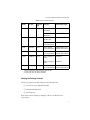
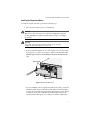
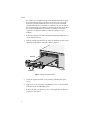
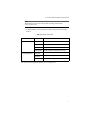
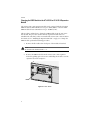
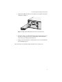
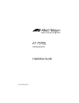
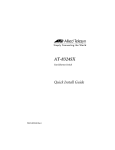
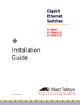
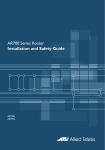
AT-A15/SX AT-A15/LX AT-A16 AT-A17 AT-A18 AT-A19 Expansion Modules Quick Install Guide PN 613-10814-00 Rev B Copyright 1999 Allied Telesyn International, Corp. 960 Stewart Drive Suite B, Sunnyvale CA 94086, USA All rights reserved. No part of this publication may be reproduced without prior written permission from Allied Telesyn International, Corp. Ethernet is a registered trademark of Xerox Corporation. All other product names, company names, logos or other designations mentioned herein are trademarks or registered trademarks of their respective owners. Allied Telesyn International, Corp. reserves the right to make changes in specifications and other information contained in this document without prior written notice. The information provided herein is subject to change without notice. In no event shall Allied Telesyn International, Corp. be liable for any incidental, special, indirect, or consequential damages whatsoever, including but not limited to lost profits, arising out of or related to this manual or the information contained herein, even if Allied Telesyn International, Corp. has been advised of, known, or should have known, the possibility of such damages. Safety Warnings Standards: This product meets the following standards U.S. Federal Communications Commission RADIATED ENERGY Note: This equipment has been tested and found to comply with the limits for a Class A digital device pursuant to Part 15 of FCC Rules. These limits are designed to provide reasonable protection against harmful interference when the equipment is operated in a commercial environment. This equipment generates, uses, and can radiate radio frequency energy and, if not installed and used in accordance with this instruction manual, may cause harmful interference to radio communications. Operation of this equipment in a residential area is likely to cause harmful interference in which case the user will be required to correct the interference at his own expense. Note: Modifications or changes not expressly approved of by the manufacturer or the FCC, can void your right to operate this equipment. Industry Canad This Class A digital apparatus meets all requirements of the Canadian Interference-Causing Equipment Regulations. Cet appareil numérique de la classe A respecte toutes les exigences du Règlement sur le matériel brouilleur du Canada. RFI Emission EN55022 Class A ! 1 WARNING: In a domestic environment this product may cause radio interference in which case the user may be required to take adequate measures. ! 2 Immunity EN50082-1 1997 ! 3 Electrical Safety TUV-EN60950, UL1950, CSA 950 ! 4 Laser EN60825 ! 5 IMPORTANT: Appendix A contains translated safety statements for installing this equipment. When you see the !, go to Appendix A for the translated safety statement in your language. WICHTIG: Anhang A enthält übersetzte Sicherheitshinweise für die Installation dieses Geräts. Wenn Sie ! sehen, schlagen Sie in Anhang A den übersetzten Sicherheitshinweis in Ihrer Sprache nach. VIGTIGT: Tillæg A indeholder oversatte sikkerhedsadvarsler, der vedrører installation af dette udstyr. Når De ser symbolet !, skal De slå op i tillæg A og finde de oversatte sikkerhedsadvarsler i Deres eget sprog. BELANGRIJK: Appendix A bevat vertaalde veiligheidsopmerkingen voor het installeren van deze apparatuur. Wanneer u de ! ziet, raadpleeg Appendix A voor vertaalde veiligheidsinstructies in uw taal. IMPORTANT: L'annexe A contient les instructions de sécurité relatives à l'installation de cet équipement. Lorsque vous voyez le symbole !, reportez-vous à l'annexe A pour consulter la traduction de ces instructions dans votre langue. TÄRKEÄÄ: Liite A sisältää tämän laitteen asentamiseen liittyvät käännetyt turvaohjeet. Kun näet !-symbolin, katso käännettyä turvaohjetta liitteestä A. IMPORTANTE: l’Appendice A contiene avvisi di sicurezza tradotti per l’installazione di questa apparecchiatura. Il simbolo !, indica di consultare l’Appendice A per l’avviso di sicurezza nella propria lingua. VIKTIG: Tillegg A inneholder oversatt sikkerhetsinformasjon for installering av dette utstyret. Når du ser !, åpner du til Tillegg A for å finne den oversatte sikkerhetsinformasjonen på ønsket språk. IMPORTANTE: O Anexo A contém advertências de segurança traduzidas para instalar este equipamento. Quando vir o símbolo !, leia a advertência de segurança traduzida no seu idioma no Anexo A. IMPORTANTE: El Apéndice A contiene mensajes de seguridad traducidos para la instalación de este equipo. Cuando vea el símbolo !, vaya al Apéndice A para ver el mensaje de seguridad traducido a su idioma. OBS! Bilaga A innehåller översatta säkerhetsmeddelanden avseende installationen av denna utrustning. När du ser !, skall du gå till Bilaga A för att läsa det översatta säkerhetsmeddelandet på ditt språk. iii Table of Contents Safety Warnings ................................................................................................................... iii Overview .................................................................................................................................1 Verifying the Package Contents .............................................................................................3 Reviewing Safety Precautions ................................................................................................4 Installing the Expansion Module ..........................................................................................5 Changing the GBIC Module in the AT-A15/SX or AT-A15/LX Expansion Module .........8 Appendix A Translated Safety Information ............................................................................................11 Appendix B AT-A1x Series Expansion Module Quick Install Guide Feedback ...................................19 Appendix C Technical Support Fax Order .............................................................................................21 Incident Summary.................................................................................................................21 Appendix D Where To Find Us ................................................................................................................23 v Overview The AT-A1x Series Expansion Modules are optional uplinks for the AT-8216FXL/ MT, AT-8216FXL/VF, AT-8216FXL/SC, and AT-8224XL Fast Ethernet Switches. The expansion modules are designed to be installed into the two expansion slots on the front of each switch. The expansion modules, which can be installed in any combination, offer you flexbility in building or expanding your network. Figure 1 through Figure 5 show the front panels while Table 1 describes each expansion module. Figure 1 AT-A15 Expansion Module (SX or LX) Figure 2 AT-A16 Expansion Module 1 Overview Figure 3 AT-A17 Expansion Module Figure 4 AT-A18 Expansion Module Figure 5 AT-A19 Expansion Module 2 AT-A1x Series Expansion Modules Quick Install Guide Table 1 Expansion Module Features Module Port Type AT-A15/SX 1000Base-SX AT-A15/LX 1000Base-LX Connector Cable Type1 Type Maximum Cable Length SC 50/125 micron multimode fiber 1,804 ft (550 m)2 62.5/125 micron multimode fiber 902 ft (275 m)3 9/125 micron singlemode fiber cable 6.2 mi (10 km) SC 50/125 or 62.5/125 1,804 ft (550 m)2 micron multimode fiber AT-A16 100Base-FX VF-45 50/125 or 62.5/125 Full-duplex 6,600 ft (2 km) micron multimode fiber Half-duplex 1,360 ft (412 m) AT-A17 100Base-FX SC 50/125 or 62.5/125 Full-duplex 6,600 ft (2 km) micron multimode fiber Half-duplex 1,360 ft (412 m) AT-A18 10/100Base-TX RJ-45 10Base-T Category 3 or better 328 ft (100 m) 100Base-T Category 5 328 ft (100 m) or better AT-A19 100Base-FX MT-RJ 50/125 or 62.5/125 Full-duplex 6,600 ft (2 km) micron multimode fiber Half-duplex 1,360 ft (412 m) 1. Refer to the IEEE 802.3 Standards for further cable information. 2. Assumes a fiber optic cable rating of 500 Mhz/Km. 3. Assumes a fiber optic cable rating of 200 Mhz/Km. Verifying the Package Contents Check your expansion module package for the following items: ❑ One AT-A1x Series Expansion Module ❑ This Quick Install Guide ❑ Warranty card If any of the items are missing or damaged, contact your Allied Telesyn representative. 3 Overview Reviewing Safety Precautions Please review the following safety precautions before you begin to install the expansion module. Laser Warning Class 1 Laser product. ! 6 Laser Warning Do not stare into the Laser beam. ! 7 Warning Lightning Danger DO NOT WORK on equipment or CABLES during periods of LIGHTNING ACTIVITY. ! 8 Warning CAUTION: POWER CORD IS USED AS A DISCONNECTION DEVICE. TO DE-ENERGISE EQUIPMENT disconnect the power cord. ! 9 Caution Air vents must not be blocked and must have free access to the room ambient air for cooling. ! 10 Caution Operating Temperature: This product is designed for a maximum ambient temperature of 40°C. ! 11 Caution All Countries: Install product in accordance with local and National Electrical Codes. ! 12 4 AT-A1x Series Expansion Modules Quick Install Guide Installing the Expansion Module To install an expansion module, perform the following steps: 1. Disconnect the switch’s power cord, if attached. Warning Make sure to disconnect the power cord before installing the expansion module. Installing an expansion module without doing so can damage the module. Warning The power cord is used as a disconnect device. To de-energize equipment, disconnect the power cord. ! 9 2. Remove a blank faceplate from one of the expansion slots by unscrewing the faceplates two captive screws. Refer to Figure 6. Do not remove the blank faceplate if you are not installing an expansion module into the slot. Captive Screws A B Blank Faceplate Figure 6 Removing the Blank Panel If you are installing only one expansion module in the switch, you should install the module in slot A. While the module will work in slot B with slot A empty, the port numbering assignments will change if you later install a module in slot A. This could affect the VLAN memberships on the switch and this could require you to adjust your VLAN configurations. 5 Overview For example, if you install an AT-A17 in slot B while leaving slot A empty, the switch will assign the port numbers 25 and 26 to the ports on the module. If you later install another AT-A17 in slot A, the switch will automatically reallocate port numbers 25 and 26 to the new modules in slot A and assign the port numbers 27 and 28 to the module in slot B. If the module in slot B had been a member of a VLAN, you would be required to reconfigure the VLAN to reflect the change to its port numbers. 3. Remove the expansion module from the packing material. Make sure you observe ESD precautions. 4. Slide the expansion module into the empty slot making sure the board is aligned properly with the card guides. Refer to Figure 7. Card Guide A ACTIVITY TX 1 RX AT-A17 TX LINK 2 ACTIVITY RX B FULL DUP HALF DUP LINK COL 100BAS E-FX/SC FULL DUP COL HALF DUP Board Dust Covers Figure 7 Installing an Expansion Module 6 5. Secure the expansion module to the switch by tightening the captive screws. 6. Apply power to the switch by re-attaching the power cord to the switch. Verify that the Power LED lights green. 7. Remove the dust cover from the port(s) on the expansion module and connect the data cable(s). AT-A1x Series Expansion Modules Quick Install Guide Note All modules except the AT-A18 modules are shipped with a dust cover over the ports. 8. Verify the LEDs on the expansion module’s front panel by referring to Table 2. Table 2 Expansion Module LEDs LED State Description Activity/Link Solid Green Indicates a 100 Mbps link. Flashing Green Indicates 100 Mbps activity. Solid Amber Indicates a 10 Mbps link (10/100 ports only). Flashing Amber Indicates 10 Mbps activity (10/100 ports only). Solid Green The port is operating at full-duplex. Solid Amber The port is operating at half-duplex. Flashing Amber Collisions are occurring on the line. Full Dup/Half Dup/Col The AT-A1x Series Expansion Module is now ready for use. 7 Overview Changing the GBIC Module in the AT-A15/SX or AT-A15/LX Expansion Module The AT-A15 (SX or LX) expansion module can be equipped with the AT-G8SX GBIC module for LED transmission of up to 1,804 ft (550 m) or the AT-G8LX GBIC module for laser transmission of up to 16,400 ft (5 km). This procedure explains how to change the GBIC module in an AT-A15 (SX or LX) module. The procedure assumes that the expansion module has been installed in the switch. If you have not installed the AT-A15 (SX or LX) module in the switch, refer to “Installing the Expansion Module” on page 5. To change the GBIC module, perform the following procedure: 1. Remove the fiber cables from both ports of the module, if attached. Laser Do not stare into the laser beam. ! 7 2. Remove the GBIC module from the AT-A15 (SX or LX) expansion module by pulling up the release wire and sliding the module out of the expansion slot. Refer to Figure 8. AT-A15 ACTIVITY LINK A 1000BASE FULL DUP -X COL HALF DUP B Release Figure 8 AT-GBIC Module 8 AT-A1x Series Expansion Modules Quick Install Guide 3. Slide the new GBIC module into the expansion slot and push it in until it clicks. Refer toFigure 9. AT-A15 ACTIVITY LINK A 1000BAS FULL DUP E-X COL HALF DUP B Figure 9 Installing a GBIC Module into the AT-A15 (SX or LX) Expansion Slot 4. Remove the dust cover and attach the fiber cables. It is important to leave the dust cover in place if you are not attaching the cables at this time. Dust in the ports will degrade transmission. 5. Apply power to the switch by re-attaching the power cord. Verify that the Power LED lights green. The AT-A15/SX or AT-A15/LX expansion module is now ready for use. 9 Appendix A Translated Safety Information IMPORTANT: This appendix contains multiple-language translations for the safety statements in this guide. WICHTIG: Dieser Anhang enthält Übersetzungen der in diesem Handbuch enthaltenen Sicherheitshinweise in mehreren Sprachen. VIGTIGT: Dette tillæg indeholder oversættelser i flere sprog af sikkerhedsadvarslerne i denne håndbog. BELANGRIJK: Deze appendix bevat vertalingen in meerdere talen van de veiligheidsopmerkingen in deze gids. IMPORTANT: Cette annexe contient la traduction en plusieurs langues des instructions de sécurité figurant dans ce guide. TÄRKEÄÄ: Tämä liite sisältää tässä oppaassa esiintyvät turvaohjeet usealla kielellä. IMPORTANTE: questa appendice contiene traduzioni in più lingue degli avvisi di sicurezza di questa guida. VIKTIG: Dette tillegget inneholder oversettelser til flere språk av sikkerhetsinformasjonen i denne veiledningen. IMPORTANTE: Este anexo contém traduções em vários idiomas das advertências de segurança neste guia. IMPORTANTE: Este apéndice contiene traducciones en múltiples idiomas de los mensajes de seguridad incluidos en esta guía. OBS! Denna bilaga innehåller flerspråkiga översättningar av säkerhetsmeddelandena i denna handledning. 11 Translated Safety Information STANDARDS: This product meets the following standards. U.S. Federal Communications Commission Note: This equipment has been tested and found to comply with the limits for a Class A digital device pursuant to Part 15 of FCC Rules. These limits are designed to provide reasonable protection against harmful interference when the equipment is operated in a commercial environment. This equipment generates, uses, and can radiate radio frequency energy and, if not installed and used in accordance with this instruction manual, may cause harmful interference to radio communications. Operation of this equipment in a residential area is likely to cause harmful interference in which case the user will be required to correct the interference at his own expense. Note: Modifications or changes not expressly approved by the manufacturer or the FCC can void your right to operate this equipment. Industry Canada Industry Canada This Class A digital apparatus meets all requirements of the Canadian InterferenceCausing Equipment Regulations. Cet appareil numérique de la classe A respecte toutes les exigences du Réglement sur le matériel brouilleur du Canada. !1 RFI Emission !2 WARNING: In a domestic environment this product may cause radio interference in which case the user may be required to take adequate measures. !3 Immunity EN50082-1 1997 !4 Electrical Safety TUV-EN60950, UL1950, CSA 950 !5 Laser EN60825 EN55022 Class A At time of installation the Fiber Optic Lasers comply with FDA Radiation Performance Standard 21CFR Subchapter J, applicable at date of manufacture. !6 Warning Class 1 Laser product. !7 Warning Do not stare into the Laser beam. Caution: Use of controls or adjustments of performance other than those specified may result in hazardous radiation exporsure. !8 LIGHTNING DANGER DANGER: DO NOT WORK on equipment or CABLES during periods of LIGHTNING ACTIVITY. !9 WARNING: POWER CORD IS USED AS A DISCONNECTION DEVICE. TO DEENERGISE EQUIPMENT disconnect the power cord. ! 10 CAUTION: Air vents must not be blocked and must have free access to the room ambient air for cooling. 12 AT-A1x Series Expansion Modules Quick Install Guide ! 11 OPERATING TEMPERATURE This product is designed for a maximum ambient temperature of 40 degrees C. ! 12 All Countries: Install product in accordance with local and National Electrical Codes. NORMEN: Dieses Produkt erfullt die Anforderungen der nachfolgenden Normen. !1 Hochfrequenzstörung !2 WARNUNG: Bei Verwendung zu Hause kann dieses Produkt Funkstörungen hervorrufen. In diesem Fall müßte der Anwender angemessene Gegenmaßnahmen ergreifen. !3 Störsicherheit EN50082-1 1997 !4 Elektrische Sicherheit TUV-EN60950, UL1950, CSA 950 !5 Laser EN60825 !6 WARNUNG Laserprodukt der Klasse 1. !7 WARNUNG Nicht direkt in den Strahl blicken. !8 GEFAHR DURCH BLITZSCHLAG GEFAHR: Keine Arbeiten am Gerät oder an den Kabeln während eines Gewitters ausführen. !9 VORSICHT: DAS NETZKABEL DIENT ZUM TRENNEN DER STROMVERSORGUNG. ZUR TRENNUNG VOM NETZ, KABEL AUS DER STECKDOSE ZIEHEN. ! 10 VORSICHT Die Entlüftungsöffnungen dürfen nicht versperrt sein und müssen zum Kühlen freien Zugang zur Raumluft haben. ! 11 BETRIEBSTEMPERATUR Dieses Produkt wurde für den Betrieb in einer Umgebungstemperatur von nicht mehr als 40° C entworfen. ! 12 ALLE LÄNDER: Installation muß örtlichen und nationalen elektrischen Vorschriften entsprechen. EN55022 Klasse A STANDARDER: Dette produkt tilfredsstiller de folgende standarder. !1 Radiofrekvens forstyrrelsesemission !2 ADVARSEL: I et hjemligt miljø kunne dette produkt forårsage radio forstyrrelse. Bliver det tilfældet, påkræves brugeren muligvis at tage tilstrækkelige foranstaltninger. !3 Immunitet EN50082-1 1997 !4 Elektrisk sikkerhed TUV-EN60950, UL1950, CSA 950 !5 Laser EN60825 EN55022 Klasse A 13 Translated Safety Information !6 ADVARSEL Laserprodukt av klasse 1. !7 ADVARSEL Stirr ikke på strålen. !8 FARE UNDER UVEJR FARE: UNDLAD at arbejde på udstyr eller KABLER i perioder med LYNAKTIVITET. !9 ADVARSEL: DEN STRØMFØRENDE LEDNING BRUGES TIL AT AFBRYDE STRØMMEN. SKAL STRØMMEN TIL APPARATET AFBRYDES, tages ledningen ud af stikket. ! 10 ADVARSEL: Ventilationsåbninger må ikke blokeres og skal have fri adgang til den omgivende luft i rummet for afkøling. ! 11 BETJENINGSTEMPERATUR Dette apparat er konstrueret til en omgivende temperatur på maksimum 40 grader C. ! 12 ALLE LANDE: Installation af produktet skal ske i overensstemmelse med lokal og national lovgivning for elektriske installationer. NORMEN: Dit product voldoet aan de volgende eisen. !1 RFI Emissie !2 WAARSCHUWING: Binnenshuis kan dit product radiostoring veroorzaken, in welk geval de gebruiker verplicht kan worden om gepaste maatregelen te nemen. !3 Immuniteit EN50082-1 1997 !4 Electrische Veiligheid TUV-EN60950, UL1950, CSA 950 !5 Laser EN60825 !6 WAARSHUWING Klasse-1 laser produkt. !7 WAARCHUWING Neit in de straal staren. !8 GEVAAR VOOR BLIKSEMINSLAG GEVAAR: NIET aan toestellen of KABELS WERKEN bij BLIKSEM. !9 WAARSCHUWING: HET TOESTEL WORDT UITGESCHAKELD DOOR DE STROOMKABEL TE ONTKOPPELEN.OM HET TOESTEL STROOMLOOS TE MAKEN: de stroomkabel ontkoppelen. ! 10 OPGELET: De ventilatiegaten mogen niet worden gesperd en moeten de omgevingslucht ongehinderd toelaten voor afkoeling. ! 11 BEDRIJFSTEMPERATUUR De omgevingstemperatuur voor dit produkt mag niet meer bedragen dan 40 graden Celsius. ! 12 ALLE LANDEN: het toestel installeren overeenkomstig de lokale en nationale elektrische voorschriften. 14 EN55022 Klasse A AT-A1x Series Expansion Modules Quick Install Guide NORMES: ce produit est conforme aux normes de suivantes: !1 Emission d’interférences radioélectriques !2 MISE EN GARDE: dans un environnement domestique, ce produit peut provoquer des interférences radioélectriques. Auquel cas, l’utilisateur devra prendre les mesures adéquates. !3 Immunité EN50082 - 1 1997 !4 Sécurité électrique TUV-EN60950, UL1950, CSA 950 !5 Laser EN60825 !6 ATTENTION Producit laser di classe 1. !7 ATTENTION Ne pas fixer le faisceau des yeux. !8 DANGER DE FOUDRE DANGER: NE PAS MANIER le matériel ou les CÂBLES lors d’activité orageuse. !9 ATTENTION: LE CORDON D’ALIMENTATION SERT DE MISE HORS CIRCUIT. POUR COUPER L’ALIMENTATION DU MATÉRIEL, débrancher le cordon. ! 10 ATTENTION: Ne pas bloquer les fentes d’aération, ceci empêcherait l’air ambiant de circuler librement pour le refroidissement. ! 11 TEMPÉRATURE DE FONCTIONNEMENT Ce matériel est capable de tolérer une température ambiante maximum de 40 degrés Celsius. ! 12 POUR TOUS PAYS: Installer le matériel conformément aux normes électriques nationales et locales. EN55022 Classe A NORMIT: Tämä tuote on seuraavien standardiem mukainen. !1 Radioaaltojen häirintä !2 VAROITUS: Kotiolosuhteissa tämä laite voi aiheuttaa radioaaltojen häiröitä, missä tapauksessa laitteen käyttäjän on mahdollisesti ryhdyttävä tarpeellisiin toimenpiteisiin. !3 Kestävyys EN50082-1 1997 !4 Sähköturvallisuus TUV-EN60950, UL1950, CSA 950 !5 Laser EN60825 !6 VAROITUS Luokan 1 Lasertuote. !7 VARIOTUS Älä katso säteeseen. !8 SALAMANISKUVAARA HENGENVAARA: ÄLÄ TYÖSKENTELE laitteiden tai KAAPELEIDEN KANSSA SALAMOINNIN AIKANA. EN55022 Luokka A 15 Translated Safety Information !9 HUOMAUTUS: VIRTAJOHTOA KÄYTETÄÄN VIRRANKATKAISULAITTEENA. VIRTA KATKAISTAAN irrottamalla virtajohto. ! 10 HUOMAUTUS: Ilmavaihtoreikiä ei pidä tukkia ja niillä täytyy olla vapaa yhteys ympäröivään huoneilmaan, jotta ilmanvaihto tapahtuisi. ! 11 KÄYTTÖLÄMPÖTILA Tämä tuote on suunniteltu ympäröivän ilman maksimilämpötilalle 40° C. ! 12 KAIKKI MAAT: Asenna tuote paikallisten ja kansallisten sähköturvallisuusmääräysten mukaisesti. STANDARD: Questo prodotto e conforme ai seguenti standard. !1 Emissione RFI (interferenza di radiofrequenza) !2 AVVERTENZA: in ambiente domestico questo prodotto potrebbe causare radio interferenza. In questo caso potrebbe richiedersi all’utente di prendere gli adeguati provvedimenti. !3 Immunit EN50082-1 1997 !4 Sicurezza elettrica TUV-EN60950, UL1950, CSA 950 !5 Laser EN60825 !6 AVVERTENZA Prodotto laser di Classe 1. !7 AVERTENZA Non fissare il raggio con gli occhi. !8 PERICOLO DI FULMINI PERICOLO: NON LAVORARE sul dispositivo o sui CAVI durante PRECIPITAZIONI TEMPORALESCHE. !9 ATTENZION : IL CAVO DI ALIMENTAZIONE È USATO COME DISPOSITIVO DI DISATTIVAZIONE. PER TOGLIERE LA CORRENTE AL DISPOSITIVO staccare il cavo di alimentazione. ! 10 ATTENZION : le prese d’aria non vanno ostruite e devono consentire il libero ricircolo dell’aria ambiente per il raffreddamento. ! 11 TEMPERATURA DI FUNZIONAMENTO Questo prodotto è concepito per una temperatura ambientale massima di 40 gradi centigradi. ! 12 TUTTI I PAESI: installare il prodotto in conformità delle vigenti normative elettriche nazionali. 16 EN55022 Classe A AT-A1x Series Expansion Modules Quick Install Guide SIKKERHETSKRAV: Dette produktet tilfredsstiller folgende sikkerhetnormer: !1 RFI stråling !2 ADVARSEL: Hvis dette produktet benyttes til privat bruk, kan produktet forårsake radioforstyrrelse. Hvis dette skjer, må brukeren ta de nødvendige forholdsregler. !3 Immunitet EN50082-1 1997 !4 Elektrisk sikkerhet TUV-EN60950, UL1950, CSA 950 !5 Laser EN60825 !6 ADVARSEL Laserprodukt av klasse 1. !7 ADVARSAL Stirr ikke på strålen. !8 FARE FOR LYNNEDSLAG FARE: ARBEID IKKE på utstyr eller KABLER i TORDENVÆR. !9 FORSIKTIG: STRØMLEDNINGEN BRUKES TIL Å FRAKOBLE UTSTYRET. FOR Å DEAKTIVISERE UTSTYRET, må strømforsyningen kobles fra. ! 10 FORSIKTIG: Lufteventilene må ikke blokkeres, og må ha fri tilgang til luft med romtemperatur for avkjøling. ! 11 DRIFTSTEMPERATUR Dette produktet er konstruert for bruk i maksimum romtemperatur på 40 grader celsius. ! 12 ALLE LAND: Produktet må installeres i samsvar med de lokale og nasjonale elektriske koder. EN55022 Klasse A PADROES: Este produto atende aos seguintes padroes: !1 Emissão de interferência de radiofrequência !2 AVISO: Num ambiente doméstico este produto pode causar interferência na radiorrecepção e, neste caso, pode ser necessário que o utente tome as medidas adequadas. !3 Imunidade EN50082-1 1997 !4 Segurança Eléctrica TUV-EN60950, UL1950, CSA 950 !5 Laser EN60825 !6 AVISO Produto laser de classe 1 !7 AVISO Não olhe fixamente para o raio. !8 PERIGO DE CHOQUE CAUSADO POR RAIO PERIGO: NÃO TRABALHE no equipamento ou nos CABOS durante períodos suscetíveis a QUEDAS DE RAIO. EN55022 Classe A 17 Translated Safety Information !9 CUIDADO: O CABO DE ALIMENTAÇÃO É UTILIZADO COMO UM DISPOSITIVO DE DESCONEXÃO. PARA DESELETRIFICAR O EQUIPAMENTO, desconecte o cabo de ALIMENTAÇÃO. ! 10 CUIDADO: As aberturas de ventilação não devem ser bloqueadas e devem ter acesso livre ao ar ambiente para arrefecimento adequado do aparelho. ! 11 TEMPERATURA DE FUNCIONAMENTO Este produto foi projetado para uma temperatura ambiente máxima de 40 graus centígrados. ! 12 TODOS OS PAÍSES: Instale o produto de acordo com as normas nacionais e locais para instalações elétricas. ESTANDARES: Este producto cumple con los siguientes estandares. !1 Emisión RFI !2 ADVERTENCIA: en un entorno doméstico, este producto puede causar radiointerferencias, en cuyo caso, puede requerirse del usuario que tome las medidas que sean convenientes al respecto. !3 Inmunidad EN50082-1 1997 !4 Seguridad eléctrica TUV-EN60950, UL1950, CSA 950 !5 Laser EN60825 !6 ¡ADVERTENCIA! Producto láser Clase 1. !7 ¡ADVERTENCIA! No mirat fijamente el haz. !8 PELIGRO DE RAYOS PELIGRO: NO REALICE NINGUN TIPO DE TRABAJO O CONEXION en los equipos o en LOS CABLES durante TORMENTAS ELECTRICAS. !9 ATENCION: EL CABLE DE ALIMENTACION SE USA COMO UN DISPOSITIVO DE DESCONEXION. PARA DESACTIVAR EL EQUIPO, desconecte el cable de alimentación. ! 10 ATENCION: Las aberturas para ventilación no deberán bloquearse y deberán tener acceso libre al aire ambiental de la sala para su enfriamiento. ! 11 TEMPERATURA REQUERIDA PARA LA OPERACIÓN Este producto está diseñado para una temperatura ambiental máxima de 40 grados C. ! 12 PARA TODOS LOS PAÍSES: Monte el producto de acuerdo con los Códigos Eléctricos locales y nacionales. 18 EN55022 Clase A Translated Safety Information STANDARDER: Denna produkt uppfyller följande standarder. !1 Radiostörning !2 VARNING: Denna produkt kan ge upphov till radiostörningar i hemmet, vilket kan tvinga användaren till att vidtaga erforderliga åtgärder. !3 Immunitet EN50082-1 1997 !4 Elsäkerhet TUV-EN60950, UL1950, CSA 950 !5 Laser EN60825 !6 VARNING! Laserprodukt av klass 1. !7 VARNING! Laserstrålning när enheten är öppen. !8 FARA FÖR BLIXTNEDSLAG FARA: ARBETA EJ på utrustningen eller kablarna vid ÅSKVÄDER. !9 VARNING: NÄTKABELN ANVÄNDS SOM STRÖMBRYTARE FÖR ATT KOPPLA FRÅN STRÖMMEN, dra ur nätkabeln. ! 10 VARNING: Luftventilerna får ej blockeras och måste ha fri tillgång till omgivande rumsluft för avsvalning. ! 11 DRIFTSTEMPERATUR Denna produkt är konstruerad för rumstemperatur ej överstigande 40 grader Celsius. ! 12 ALLA LÄNDER: Installera produkten i enlighet med lokala och statliga bestämmelser för elektrisk utrustning. 19 EN55022 Klass A Appendix B AT-A1x Series Expansion Module Quick Install Guide Feedback Please tell us what additional information you would like to see discussed in this guide. If there are topics you would like information on that were not covered in this guide, please photocopy this page, answer the questions and fax or mail this form back to Allied Telesyn. The mailing address and fax number are at the bottom of the page. Your comments are valuable when we plan future revisions of this guide. I found the following the most valuable __________________________________ ______________________________________________________________________ ______________________________________________________________________ ______________________________________________________________________ I would like the following more developed ________________________________ ______________________________________________________________________ ______________________________________________________________________ ______________________________________________________________________ I would find this guide more useful if ____________________________________ ______________________________________________________________________ ______________________________________________________________________ ______________________________________________________________________ Please fax or mail your feedback. Fax to 1-408-736-0100. Or mail to: Allied Telesyn International, Corp. c/o Technical Communications 960 Steward Drive, Suite B Sunnyvale, CA 94086 USA PN 613-10814-00 Rev B 19 Appendix C Technical Support Fax Order Name ________________________________________________________________________ Company_____________________________________________________________________ Address______________________________________________________________________ City ___________________________State/Province__________________________________ Zip/Postal Code ______________________ Country__________________________________ Phone __________________________________ Fax__________________________________ Incident Summary Allied Telesyn model number ____________________________________________________ Firmware release number of Allied Telesyn product (if applicable)______________________ Other network software products I am using (e.g., network managers) _____________________________________________________________________________ _____________________________________________________________________________ Brief summary of problem ______________________________________________________ _____________________________________________________________________________ Conditions (List the steps that led up to the problem.)________________________________ _____________________________________________________________________________ _____________________________________________________________________________ _____________________________________________________________________________ _____________________________________________________________________________ _____________________________________________________________________________ _____________________________________________________________________________ _____________________________________________________________________________ Detailed description (Please use separate sheet) Please also fax printouts of relevant files such as batch files and configuration files. When completed, fax this sheet to the appropriate Allied Telesyn office. Fax numbers can be found on page 19. 21 Appendix D Where To Find Us For Technical Support or Service Location Phone Fax Americas United States, Canada, Mexico, Central America, South America 1 (800) 428-4835 1 (503) 639-3946 Asia Singapore, Taiwan, Thailand, Malaysia, Indonesia, Korea, Philippines, China, India, Hong Kong (+65) 3815-612 (+65) 3833-830 Australia Australia, New Zealand 1 (800) 000-880 (+61) 2-9438-4966 France France, Belgium, Luxembourg, The Netherlands, Middle East, Africa (+33) 1-60-92-15-25 (+33) 1-69-28-37-49 Germany Germany, Switzerland, Austria, Eastern Europe (+49) 30-435-900-126 (+49) 30-435-70-650 Italy Italy, Spain, Portugal, Greece, Turkey, Israel (+39) 02-416047 (+39) 02-419282 Japan (+81) 3-3443-5640 (+81) 3-3443-2443 United Kingdom United Kingdom, Denmark, Norway, Sweden, Finland, Iceland (+44) 1-235-442560 (+44) 1-235-442680 Technical Support E-mail Address [email protected] FTP Server Address: gateway.centre.com [lowercase letters] Login: anonymous [lowercase letters] Password: your e-mail address [requested by the server at login] For Corporate and Sales Information Allied Telesyn International, Corp. 19800 North Creek Parkway, Suite 200 Bothell, WA 98011 Tel: 1 (425) 487-8880 Fax: 1 (425) 489-9191 Allied Telesyn International, Corp. 960 Stewart Drive, Suite B Sunnyvale, CA 94086 Tel: 1 (800) 424-4284 (USA and Canada) Fax: 1 (408) 736-0100 World Wide Web http://www.alliedtelesyn.com 23