1
Version 1.0
Produced in July 2002
Compact Color Image Sensor Camera
User’s Manual (Function and Operation)
Thank you for purchasing the SHARP IV-C35M compact color image sensor camera. Read this introductory
user's manual carefully to thoroughly familiarize yourself with the functions and proper procedures for
operation.
Store this user's manual in a safe place. We are confident that the manual will be helpful whenever you
encounter a problem.
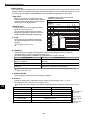
In addition to this manual, there are two other IV-C35M manuals as follows. Read them in conjunction with this
manual.
IV-C35M
User’s Manual (Introduction and Hardware)
User’s Manual (Function and Operation: This manual)
Instruction Manual
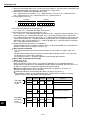
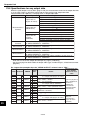
Manual type
Major subjects
- Outline of the IV-C35M (features and
functions)
IV-C35M
- Description of the hardware
User's Manual
- Startup method
(Introduction and Hardware)
- General performance specifications.
- Example of operation and instruction
- Detailed explanations of all the
measurement functions.
- How to make menu selections for
IV-C35M
each measurement
User's manual
- Details of inputting and outputting
(Function and Operation)
data and communications with other
devices.
- Troubleshooting
How to use
- Become acquainted with the IV-C35M
- Learn how to install the IV-C35M and
wire it up
- When mastering the outline of
operation.
- Learn how to specify measurement
/inspection conditions, good or NG
judgment conditions, etc.
- Lear how to connect a programmable
controller or personal computer.
- Learn what to do if a problem occurs.
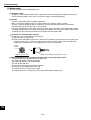
Notes
- This manual was written with the utmost care. However, if you have any questions or
inquiries concerning the product, please feel free to contact our dealers or service agents.
- Copying all or part of this booklet is prohibited.
- The contents of this manual may be revised or modified for improvement without prior
notice.
Setting the Operating and System Conditions
Chapter
Chapter
Chapter
Chapter
Chapter
Chapter
Chapter
Chapter
Chapter
Chapter
Chapter
Chapter
Chapter
Chapter
Chapter
Chapter
Chapter
Chapter
Chapter
Chapter
Chapter
Chapter
Chapter
Chapter
Setting Measurement Conditions
1:
Setting and
Operating
Outline
Positional
Deviation
Measurement
2: Setting the Operating and System Conditions
Degree of Match Inspection
3: Setting Measurement Conditions
Lead Inspection
4: Positional Deviation Measurement
BGA/CSP Inspection
5: Degree of Match Inspection
Area Measurement by Binary Conversion
6: Lead Inspection
Object Counting by Binary Conversion
7: BGA/CSP Inspection
Object Identification by Binary Conversion
8: Area Measurement by Binary Conversion
Color Evaluation
9: Object Counting by Binary Conversion
Color Unevenness Inspection
10: Object Identification by Binary Conversion
Color Position Measurement
11: Color Evaluation
Existence
Inspection by
Point Measurement
12:
Color Unevenness
Inspection
Multiple
Measurement
13:
ColorPosition
Positional
Measurement
Multiple
of Match Inspection
14:
PointDegree
Measurement
Fault
Inspection
15:
Multiple
Positional Measurements
Distance
and
Angleof
Measurement
16:
Multiple
Degree
Match Inspection
Numerical
Calculations
17:
Fault Inspection
PC Distance
Function and Angle Measurement
18:
Setting
the Input/Output
Conditions
19:
Numerical
Calculations
20:
PC Function(General Purpose Serial Interface)
Communication
21:
Setting Link
the Input/Output Conditions
Computer
22:
Communication (General Purpose Serial Interface)
Troubleshooting
23:
ComputerIndex
Link
Alphabetical
24: Troubleshooting
Alphabetical Index
Table of Contents
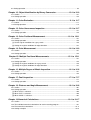
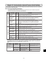
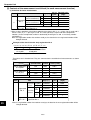
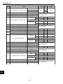
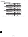
Chapter 1: Setting and Operating Outline ................................................... 1-1 to 1-31
1-1 Setting and operating procedures ................................................................................................ 1-1
1-2 Method for selecting the menu configuration ............................................................................... 1-2
[1] Menu configuration .................................................................................................................... 1-4
[2] Configuration of the setting conditions ....................................................................................... 1-5
[3] Configuration of Set Wizard ....................................................................................................... 1-6
1-3 Description of the Operation screen .......................................................................................... 1-10
1-4 Setting the measurement programs .......................................................................................... 1-13
1-5 Common operations for each menu .......................................................................................... 1-14
[1] Operations to return to the operation screen ........................................................................... 1-14
[2] Saving data .............................................................................................................................. 1-14
1-6 Power ON setting menu ............................................................................................................. 1-15
[1] Operations menu lock .............................................................................................................. 1-15
[2] Change the Japanese or English display mode ....................................................................... 1-15
1-7 Remote keypad (IV-S30RK1) .................................................................................................... 1-16
1-8 Register and display NG images ............................................................................................... 1-17
[1] How to register NG images ...................................................................................................... 1-17
[2] How to display NG images ....................................................................................................... 1-19
[3] Initializing the NG images ........................................................................................................ 1-23
1-9 Operation flow ............................................................................................................................ 1-24
[1] Power ON and main loop processing ...................................................................................... 1-24
[2] Operation flow after the measurement start input is turned ON. .............................................. 1-26
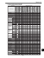
1-10 Table of controller functions ..................................................................................................... 1-29
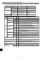
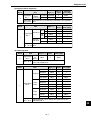
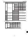
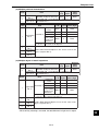
Chapter 2: Setting the Operating and System Conditions ......................... 2-1 to 2-23
2-1 Setting the operating conditions .................................................................................................. 2-1
[1] Monitor output ............................................................................................................................ 2-2
[2] Image capture ............................................................................................................................ 2-4
[3] Message display ........................................................................................................................ 2-5
[4] Pattern display ........................................................................................................................... 2-6
[5] Binary image display .................................................................................................................. 2-7
[6] θ angle correction image display ............................................................................................... 2-8
[7] Operation main display .............................................................................................................. 2-9
[8] Evaluation change display ....................................................................................................... 2-10
[9] PC monitor screen ................................................................................................................... 2-11
[10] Through display ...................................................................................................................... 2-11
[11] Extension functions ................................................................................................................ 2-12
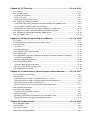
2-2 Setting the system conditions .................................................................................................... 2-14
[1] Manually setting the object type ............................................................................................... 2-14
[2] Gain/offset adjustment ............................................................................................................. 2-15
[3] Setting the system time ............................................................................................................ 2-16
2-3 Camera settings ......................................................................................................................... 2-17
[1] Camera selection ..................................................................................................................... 2-17
[2] Image capture mode ................................................................................................................ 2-18
2-4 Editing Operation screen ........................................................................................................... 2-19
2-5 Option ........................................................................................................................................ 2-20
2-6 Environment settings ................................................................................................................. 2-21
2-7 Memory card .............................................................................................................................. 2-22
Chapter 3 : Setting Measurement Conditions ............................................. 3-1 to 3-54
3-1 Outline ......................................................................................................................................... 3-1
3-2 Shared settings ............................................................................................................................ 3-4
[1] Camera selection ....................................................................................................................... 3-4
[2] Color filter ................................................................................................................................... 3-5
[3] Color extraction ...................................................................................................................... 3-10
[4] Window shape selection and settings ...................................................................................... 3-15
[5] Image settings .......................................................................................................................... 3-20
[6] Evaluation conditions ............................................................................................................... 3-28
[7] Image pre-processing .............................................................................................................. 3-29
[8] Color image correction ............................................................................................................. 3-35
[9] Image adjustment .................................................................................................................... 3-36
[10] Binary image mask ................................................................................................................ 3-37
[11] Positional correction ............................................................................................................... 3-42
[12] Title registration ...................................................................................................................... 3-45
[13] Setting shortcut function ........................................................................................................ 3-46
3-3 Input & Output / System settings ............................................................................................... 3-48
[1] Illuminance (light level) monitor ............................................................................................... 3-48
[2] Setting the shutter speed ......................................................................................................... 3-50
[3] Copying .................................................................................................................................... 3-51
[4] NG image registration .............................................................................................................. 3-52
[5] Halt on NG measurement ........................................................................................................ 3-53
[6] Window group move ................................................................................................................ 3-54
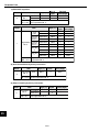
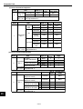
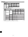
Chapter 4: Positional Deviation Measurement ............................................ 4-1 to 4-14
4-1 Outline .........................................................................................................................................
4-2 Setting operation ..........................................................................................................................
[1] Setting the register conditions for a gray search ........................................................................
[2] Setting the register conditions for edge detection ......................................................................
4-1
4-2
4-5
4-8
Chapter 5: Degree of Match Inspection ......................................................... 5-1 to 5-9
5-1 Outline ......................................................................................................................................... 5-1
5-2 Setting operation .......................................................................................................................... 5-2
Chapter 6: Lead Inspection ............................................................................. 6-1 to 6-8
6-1 Outline ......................................................................................................................................... 6-1
6-2 Setting operation .......................................................................................................................... 6-2
Chapter 7: BGA/CSP Inspection ..................................................................... 7-1 to 7-8
7-1 Outline ......................................................................................................................................... 7-1
7-2 Setting operation .......................................................................................................................... 7-2
Chapter 8: Area Measurement by Binary Conversion .................................. 8-1 to 8-9
8-1 Outline ......................................................................................................................................... 8-1
8-2 Setting operation .......................................................................................................................... 8-2
Chapter 9: Object Counting by Binary Conversion ...................................... 9-1 to 9-8
9-1 Outline ......................................................................................................................................... 9-1
9-2 Setting operation .......................................................................................................................... 9-2
Chapter 10: Object Identification by Binary Conversion .......................... 10-1 to 10-9
10-1 Outline ..................................................................................................................................... 10-1
10-2 Setting operation ...................................................................................................................... 10-2
Chapter 11: Color Evaluation ...................................................................... 11-1 to 11-7
11-1 Outline .......................................................................................................................................11-1
11-2 Setting operation ....................................................................................................................... 11-2
Chapter 12: Color Unevenness Inspection ................................................ 12-1 to 12-7
12-1 Outline ..................................................................................................................................... 12-1
12-2 Setting operation ...................................................................................................................... 12-2
Chapter 13: Color Positional Measurement ............................................. 13-1 to 13-11
13-1 Outline .....................................................................................................................................
13-2 Setting operation ......................................................................................................................
[1] Set the register conditions for a gray search ...........................................................................
[2] Setting the register conditions for edge detection ....................................................................
13-1
13-2
13-5
13-7
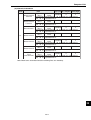
Chapter 14: Point Measurement ................................................................. 14-1 to 14-9
14-1 Outline ..................................................................................................................................... 14-1
14-2 Setting operation ...................................................................................................................... 14-2
Chapter 15: Multiple Positional Measurements ..................................... 15-1 to 15-11
15-1 Outline .....................................................................................................................................
15-2 Setting operation ......................................................................................................................
[1] Setting the register conditions for a gray search ......................................................................
[2] Setting the register conditions for edge detection ....................................................................
15-1
15-2
15-5
15-7
Chapter 16: Multiple Degree of Match Inspection ..................................... 16-1 to 16-8
16-1 Outline ..................................................................................................................................... 16-1
16-2 Setting operation ...................................................................................................................... 16-2
Chapter 17: Fault Inspection ....................................................................... 17-1 to 17-7
17-1 Outline ..................................................................................................................................... 17-1
17-2 Setting operation ...................................................................................................................... 17-2
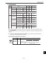
Chapter 18: Distance and Angle Measurement ......................................... 18-1 to 18-8
18-1 Outline .....................................................................................................................................
18-2 Setting operation ......................................................................................................................
[1] When "AUX" is selected ...........................................................................................................
[2] When "DST" is selected ...........................................................................................................
[3] When "ANGL" is selected ........................................................................................................
18-1
18-2
18-4
18-6
18-7
Chapter 19 Numerical Calculations .......................................................... 19-1 to 19-17
19-1 Outline ..................................................................................................................................... 19-1
19-2 The individual numerical calculations for each measuring program ........................................ 19-1
19-3 Final numerical calculations .................................................................................................... 19-11
19-4 Setting examples ................................................................................................................... 19-13
Chapter 20: PC Function ........................................................................... 20-1 to 20-19
20-1 Outline ..................................................................................................................................... 20-1
20-2 Operation cycle ........................................................................................................................ 20-1
[1] Power ON sequence ................................................................................................................ 20-2
[2] PC scan cycle .......................................................................................................................... 20-2
[3] Measurement processing cycle ............................................................................................... 20-2
20-3 Ladder circuit program creation .............................................................................................. 20-3
[1] Procedure for creating measurement output condition and a ladder circuit ............................. 20-3
[2] A list of the "OUTPUT COND" screen displays ........................................................................ 20-9
[3] Procedure for creating the final output conditions in a ladder circuit ..................................... 20-12
20-4 Program examples (shape and positional deviation inspection) ........................................... 20-17
20-5 Examples of a final output conditions ladder circuit .............................................................. 20-18
20-6 PC monitor screen ................................................................................................................ 20-19
Chapter 21: Setting the Input/Output Conditions ................................... 21-1 to 21-34
21-1 Outline ..................................................................................................................................... 21-1
21-2 Measurement start input and result output settings ................................................................. 21-5
21-3 CCD trigger ............................................................................................................................ 21-18
[1] Outline .................................................................................................................................... 21-18
[2] Setting procedure ................................................................................................................... 21-18
21-4 Setting for serial communications .......................................................................................... 21-23
21-5 Computer link ......................................................................................................................... 21-24
21-6 Output block assignment (Computer link output and general purpose serial output) ............ 21-25
[1] Data in specified blocks ......................................................................................................... 21-25
[2] Setting (operating) procedure ................................................................................................ 21-26
21-7 Setting the data output ........................................................................................................... 21-28
[1] Select "ANY" for the serial output .......................................................................................... 21-28
[2] Select "YES" or "NO" for output data ..................................................................................... 21-29
21-8 Calibrating the IV-C35M ......................................................................................................... 21-30
Chapter 22: Communication (General Purpose Serial Interface) .......... 22-1 to 22-17
22-1 List of processing functions ..................................................................................................... 22-1
22-2 Data flow .................................................................................................................................. 22-3
[1] Measurement execution 1: Command codes 10, 11, or 12 ..................................................... 22-3
[2] Measurement execution 2: Response processing for command 11 ........................................ 22-3
[3] Measurement execution 3: Command 14 ................................................................................ 22-4
[4] Processing other than measurement execution processing .................................................... 22-4
22-3 Communication format ............................................................................................................. 22-5
22-4 Processing functions ................................................................................................................ 22-7
[1] Measurement execution functions ........................................................................................... 22-7
[2] Result reading .......................................................................................................................... 22-9
[3] Setting, initialization, and diagnosis of the operation screen ................................................. 22-12
[4] Setting numerical data of the any output measuring .............................................................. 22-16
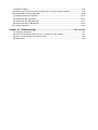
Chapter 23: Computer Link ....................................................................... 23-1 to 23-35
23-1 Compatible models ..................................................................................................................
23-2 Data flow ..................................................................................................................................
23-3 Register setting ........................................................................................................................
23-4 Measurement data blocks ........................................................................................................
23-1
23-2
23-3
23-5
[1] Number of blocks ..................................................................................................................... 23-5
[2] Contents of the measurement result block (for each measurement function) ......................... 23-6
23-5 Specifications for any output data .......................................................................................... 23-18
[1] Setting items for the IV-C35M ................................................................................................ 23-20
[2] Connection with a Sharp PC .................................................................................................. 23-21
[3] Connection with a Mitsubishi PC ........................................................................................... 23-27
[4] Connection with an OMRON PC ............................................................................................ 23-30
23-7 Program examples ................................................................................................................. 23-32
Chapter 24: Troubleshooting ...................................................................... 24-1 to 24-6
[1] Symptoms and checks .............................................................................................................
[2] Causes of termination codes (when an error occurs) and remedies .......................................
[3] Causes and treatments for error messages .............................................................................
[4] Maintenance ............................................................................................................................
24-1
24-3
24-5
24-6
Setting and Operating Outline
Chapter 1: Setting and Operating Outline
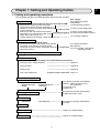
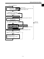
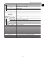
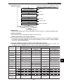
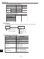
1-1 Setting and operating procedures
This paragraph describes the rough operation sequence of the IV-C35M.
1 System design
Plan your hardware environment to suit your use of the IV-C35M.
- Measurement program (positional deviation
measurement, degree of match inspection, etc.)
- Number of cameras, externally connected devices,
system components
- Selection of color and monochrome cameras
- Input/output (start measurement input, result
output, object type change, etc.)
- Lighting equipment, illumination, shutter speed, lens, etc.
2 Installation/assembly
Install the hardware you will be using.
- Connection of cameras and monitor to the controller
- Installation of the controller and camera body
- Connection of a power supply, input/output terminals
and external devices
(Ref. chapter)
User’s Manual (Instruction
and Hardware)
1-4 Measurement programs
3-1 Basic system configuration
3-1 Basic system configuration
3-2 System configuration examples
5-1 Installation conditions
User’s Manual (Instruction
and Hardware)
5-2 to 5-3 Installing, connectiong,
and wiring methods
3 Turning ON the power supply (controller and monitor)
Supply power to each device.
4 Environment settings
Set IV-C35M parameters according to the actual hardware environment.
- Setting the Input / Output conditions
Chapter 21
- Communication
Chapter 22
- Computer link
Chapter 23
- Gain / offset adjustment
Page 2-15
5 Enter measuring programs
Entered using the
wizard
Entered using the
menu tree
User’s Manual (Instruction and Hardware)
Chapter 7: Setting Examples Using
the Set Wizard
6-4 Operation chart
6-5 Menu tree
User’s Manual (Instruction and Hardware)
6-7 Editing operation screen
6 Editing Operation screen
7 Other settings
Initialization
User’s Manual (Instruction and Hardware)
6-8 Option
Self Diagnosis
8 Operation
9 Test/inspection
Chapter 24: Troubleshooting
0 Maintenance
Chapter 24: Troubleshooting
1-1
1
Setting and Operating Outline
1
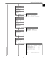
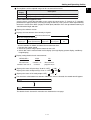
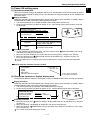
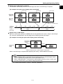
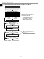
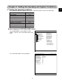
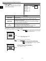
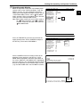
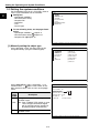
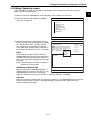
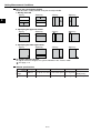
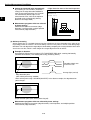
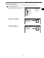
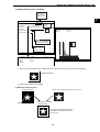
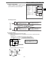
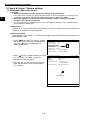
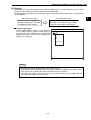
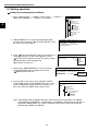
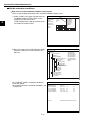
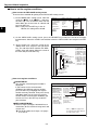
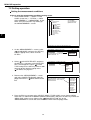
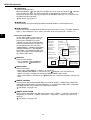
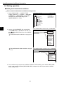
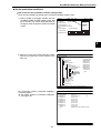
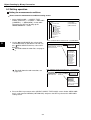
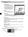
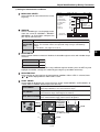
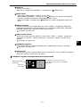
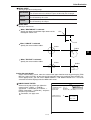
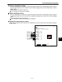
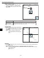
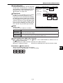
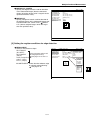
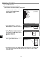
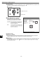
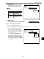
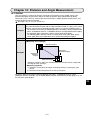
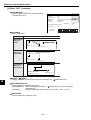
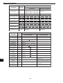
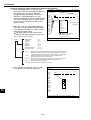
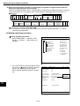
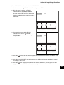
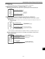
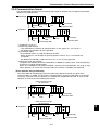
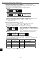
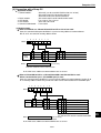
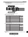
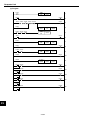
1-2 Method for selecting the menu configuration
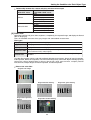
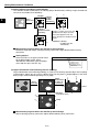
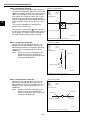
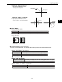
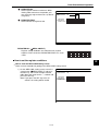
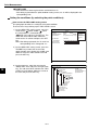
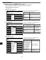
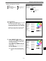
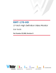
(1) Set wizard
The IV-C35M has a "Set Wizard" function to assist beginners in setting the measurement conditions.
Select "SET WIZARD" from the "MAIN MENU" and the wizard will show the
items needed for each step. You only need to make selections according the
instructions on the screen. Using the wizard, you can establish the minimum
required settings for making measurements.
STEP1
SELECT THE MEASUREMENT
START INPUT I/F
1PARALLEL+SERIAL+USB ■
2TRIG CCD START
□
STEP2
SELECT AN IMAGE CAPTURING
METHOD DURING OPERATION
1PARTIAL-IMG
■
2ALL IMAGE
□
3NO CAPTURED
□
・・・
IVC35M
SYS-CND
OBJECT TYPE COND
SET WIZARD
EDIT MAIN OPS MENU
OPTION
ENVIRONMENT SETTING
MEMORY CARD
STEP9
STORE THIS SETTING AS A
SAMPLE IN THE WIZARD?
1NO
□
2YES
■
RETURN END
NEXT DETAIL
ENTER A SHUTTER SPEED
(1/30∼1/10000)
1SHUTTER SPEED 1/00060
RETURN NEXT
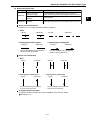
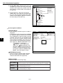
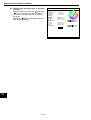
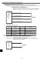
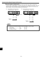
The steps that the set wizard takes you through are displayed as lists on the
"operation chart." At any point you can return to the previous step to make a
change if you want to.
TYPE00
Start
STEP1:PARALLEL+SERIAL+USB
STEP2:CAPTURE IMG/PARTIAL-IMG
STEP3:COLOR IMAGE CORRECT
STEP4:MEAS1/CAM1
STEP5:MEAS1/F/BIN-AREA
STEP6:MEAS1/WINDOW/MASK,1
STEP7:MEAS1/MEAS CND
STEP8:MEAS1/EVALUATION
STEP9:MEAS1/CALC
STEP10:MEAS1/OUT
STEP11:FINAL NUMERIC CALC
STEP12:FINAL OUTPUT COND
STEP13:SERIAL OUTPUT/ANY
STEP14:OPS MENU COND
STEP15:CALIBRATION/YES
STEP16:MOVE ALL WINDOW/YES
STEP17:TITLE/YES
End
Wizard
The "Wizard" is a program that helps users make settings for measurement operations easily and
without making mistakes. The controller asks you a series of questions at each step and you
simply answer these to complete the settings.
The wizard is convenient for making settings when beginners and inexperienced operators are
operating the machine. However, operators who are familiar with the operation may save a lot of
time by using other setting methods.
1-2
Setting and Operating Outline
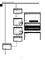
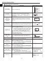
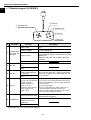
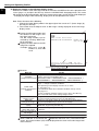
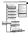
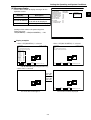
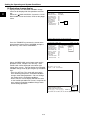
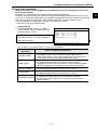
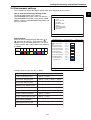
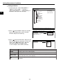
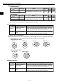
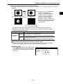
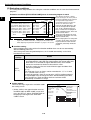
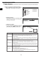
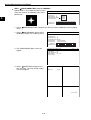
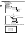
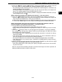
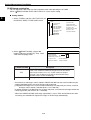
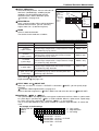
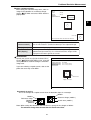
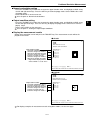
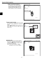
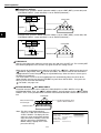
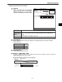
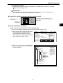
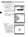
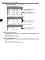
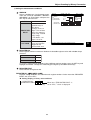
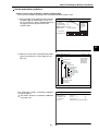
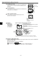
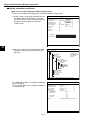
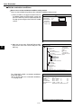
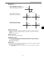
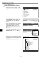
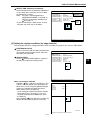
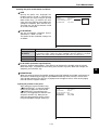
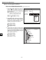
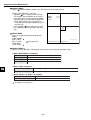
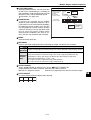
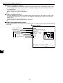
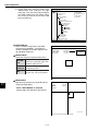
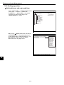
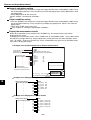
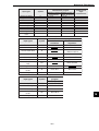
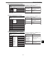
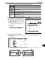
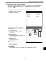
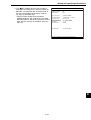
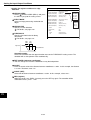
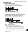
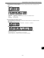
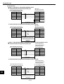
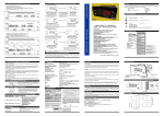
(2) Menu tree
The IV-C35M has a menu tree which is shown the hierarchy of choices on
each screen. To return to the previous screen or go to next screen, select
the corresponding item on the menu tree.
OBJECT TYPE COND
TYPE00
TYPE01
TYPE RUN COND
IMAGE-ADJ
MEA-CND(CAMERA1)
MEAS0 (POSI-DEVIATION)
POSI-CORRECT
MEAS01(MEAS-BIN-AREA F)
MEAS(NEW)
MEA-CND(CAMERA2)
FINAL NUM. CALC
FINAL OUTPUT COND
OBJ-TYPE I/0
OBJ-TYPE SYS.
TYPE(NEW)
How to enter the menu tree
On the "MAIN MENU" select "OBJECT TYPE COND" to enter the menu
tree.
and
mean that a sub men is available inside the menu.
Select
and press the SET key or the right arrow key, the next level of
menu will be opened.
When
is shown, it means that the lower menu level is already open.
Sub menu is
displayed
Have sub menus
not yet displayed
OBJECT TYPE COND
TYPE00
TYPE01
TYPE RUN COND
IMAGE-ADJ
MEA-CND(CAMERA1)
MEAS0 (POSI-DEVIATION)
POSI-CORRECT
MEAS01(MEAS-BIN-AREA F)
MEAS(NEW)
MEA-CND(CAMERA2)
FINAL NUM. CALC
FINAL OUTPUT COND
OBJ-TYPE I/0
OBJ-TYPE SYS.
TYPE(NEW)
1-3
IVC35M
SYS-CND
OBJECT TYPE COND
SET WIZARD
EDIT MAIN OPS MENU
OPTION
ENVIRONMENT SETTING
MEMORY CARD
1
Setting and Operating Outline
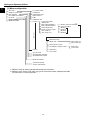
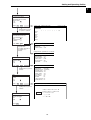
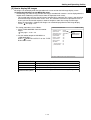
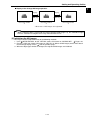
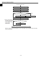
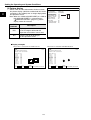
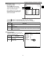
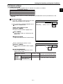
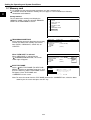
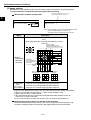
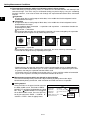
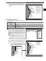
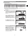
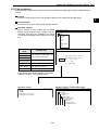
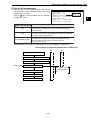
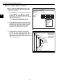
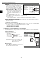
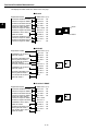
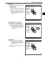
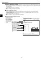
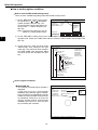
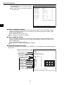
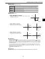
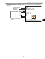
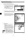
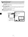
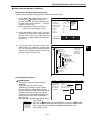
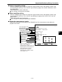
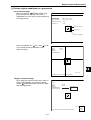
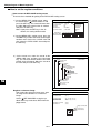
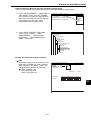
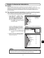
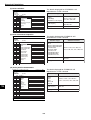
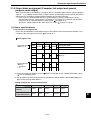
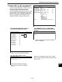
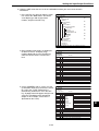
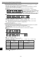
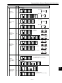
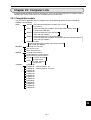
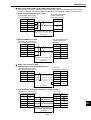
[1] Menu configuration
SYS-CND
OBJECT TYPE COND
SET WIZARD
EDIT MAIN OPS MENU
OPTION
ENVIRONMENT SETTING
MEMORY CARD
I/O CONDITIONS
COMM.SET
COMPUTER LINK
GAIN.OFFSET
TIME
CAMERA TYPE
TYPE00
(max. 32)
1
TYPE RUN COND
IMAGE-ADJ
MEA-CND(CAMERA1)
MEA-CND(CAMERA2)
FINAL NUM.CALC
FINAL OUTPUT COND
OBJ-TYPE I/O
OBJ-TYPE SYS.
(*1)
MEAS0 (POSI-DEVIATION)
POSI-CORRECT
MEAS01
MEAS02
MEAS03 *2
MEAS04
IMG PRE-PROC
MEAS CND
EVALUATION COND
DISTANCE & ANGLE COND
NUM-CALC
OUT-COND
TYPE31
1CHG-TYPE
2STANDARD WIZARD
3OPERATION CHART
MAIN OPS MENU
1INITIALIZATION
2SELF DIAGNOSIS
*1: MEAS0 is only for making "positional deviation measurements."
*2: MEAS01 to 04 can be set to make any type of measurement from "positional deviation
measurements" to "fault inspection."
1-4
REG-COND (S)
REG-COND (E)
NUM-CALC
OUT-COND
Setting and Operating Outline
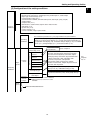
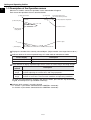
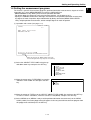
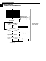
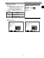
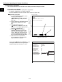
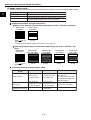
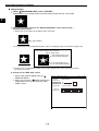
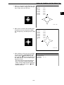
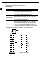
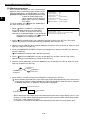
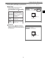
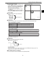
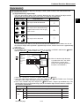
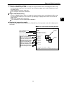
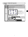
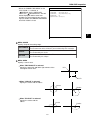
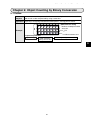
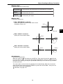
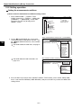
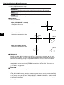
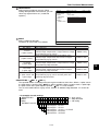
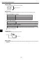
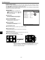
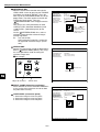
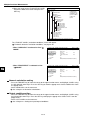
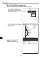
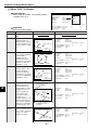
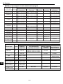
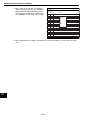
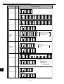
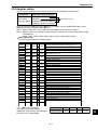
[2] Configuration of the setting conditions
- I/O conditions (21-1)
Measurement start input I/F, parallel input X6, parallel input X7, strobe output
- Object type manual change (2-14)
- Communication setting (22-1)
Communication standard, communication speed, data length, parity, stop bit,
station number
- Computer link (23 -1)
Manufacturer, station number, top line of the written results
- Gain/offset (2-15)
- System time (2-16)
- Camera setting (2-17)
Camera selection, image capture mode
System
conditions
The numbers in parentheses ( ) are page numbers for your reference.
Output monitor (2-2), image capture (2-4), message display (2-5), pattern
display (2-6), binary image display (2-7), q angle correction image display (28), operation main display (2-9), evaluation change display (2-10), PC monitor
screen (2-11), through display (2-11), extension functions (2-12).
Operating
conditions
Object
type 00
Camera
1 and 2
Measuring program
Image preprocessing (3-20)
Measurement 0,
camera 1
Measurement 0,
camera 2
Measurement 1
Measurement 2
Measurement 3
Measurement 4
Measuring
conditions
Input and output for
each object type
System for
each object
Camera 1
and NG
images
Object
type 01
・
・
・
Positional deviation
- See Chapter 4
measurement
Positional deviation measurement, degree of match
inspection, lead inspection, BGA/CSP inspection,
area measurement by binary conversion, object
See
counting by binary conversion, object identification
by binary conversion, color evaluation, color
- Chapters
4 to 17.
unevenness inspection, color position
measurement, point measurement, multiple
positions measurement, multiple degree of match
inspection, fault inspection.
CCD trigger (21-18), shutter speed (3-37), serial
output (21-24, 26), calibration setting (21-28).
Monitor light level (3-35), register NG images (3-39),
stop NG measurement (3-40), whole group move (341)
Same for Camera 1 and 2. However,
"Measurement 0, Camera 2" is not
available.
Same for "Measurement 00."
1-5
1
Setting and Operating Outline
1
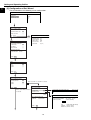
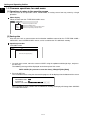
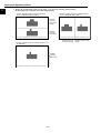
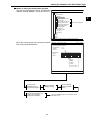
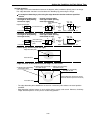
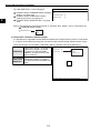
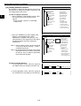
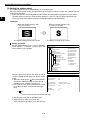
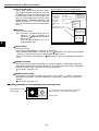
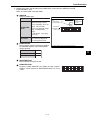
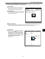
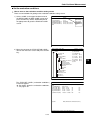
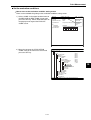
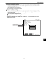
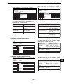
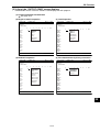
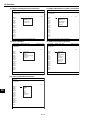
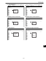
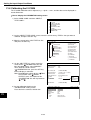
[3] Configuration of Set Wizard
The Set Wizard has the following screen configuration.
F C1 BRT
SET WIZARD SCREEN SAVE DEL
[SAMPLE]
1CHG-TYPE
2STANDARD WIZARD
3OPERATION CHART
TYPE00
Start
End
STEP1
SELECT THE MEASUREMENT
START INPUT I/F
1PARALLEL+SERIAL+USB
■
2TRIG CCD START
□
NEXT
COMM.SET
DETAIL
When "DETAIL" is selected.
STEP2
SELECT AN IMAGE CAPTURING
METHOD DURING OPERATION
1PARTIAL-IMG
■
□
2ALL IMAGE
□
3NO CAPTURED
SCREEN COND SAVE
1COMM.STANDARD
2BAUDRATE (kdps)
3NO.OF DATA BITS
4PARITY CHECK
5NO.O STOP BITS
6STATION NO.
RS232C
115.2
7BIT
EVEN
2BIT
00(0~7F)
ENTER ASHUTTER SPEED
(1/30~1/10000)
1SHUTTER SPEED 1/00060
RETURN NEXT
STEP3
CORRECT POSITION?
1NO
2CAM1
3CAM2
■
□
□
RETURN NEXT
STEP3
SELECT A CAMERA TO SPECIFY
MEASUREMENT CONDITIONS
1NO REGISTRATION
■
■
2CAM1
□
3CAM2
RETURN
NEXT
When "2CAM1" or "3CAM2" is selected.
STEP4
SELECT A COLOR IMAGE
PROCESSING MODE
When "1NO REGISTRATION" 1COLOR FILTER
is selected.
2EXTRACT COLOR
■
□
COLOR FILTER SET SCREEN COND SAVE
1FILTER TYPE
RED F C1 BRT
RED
COLOR FILTER SET
DETAIL
SELECT A MEASUREMENT TYPE
1MEAS SEL
POSI-DEVIATION
RETURN
SET EXTRACT COLOR SCREEN COND SAVE
1EXTRACT COLOR NO
2COLOR EXTRACTION AREA
3FINE ADJUSTMENT
COLOR
0(0~7)
SET (248,232) ~ (263,247)
(TO NEXT SUB-MENU)
HUE
(START PNT080 END PNT060)
CHROMA
(U.LM130 L.LM110)
BRIGHT LEV (U.LM130 L.LM110)
NEXT
1-6
Setting and Operating Outline
1
STEP4
SELECT TYPE OF CALCUATION
BETWEEN IMAGES
1COMPARE IMGS NO
SELECT WHETHER OR NOT TO
CONVERT IMGE DENSITY
1CHNG GRAY LEVELNO
SELECT FILTER TYPE FOR
IMAGE DATA
1SPACE FILTER
NO
RETERN
COMPARE IMGS
NEXT DETAIL
SCREEN
1CALC.TYPE
2CALC.AREA
NO
SET
SAVE
(232,216)-(279,263)
1Displayed when the "CAM1" or "CAM1&2" is selected in item "1COMPARE IMGS"
STEP5
1REGISTER NO.(0~7) 0
SELECT AN IMAGE PROCESSING
1NO
□
2GRAY-SRC
■
□
3EDGE DTECT
□
4SCH-EDGE
1NUM.OF DTECT
1P
ENTER A RANGE AND UNITS FOR
ROTATION ANGLE DETECTION
1DTECT ANGL NO
RETURN NEXT DETAIL
REG COND
STEP6
1REGISTER NO.
2MEAS SHAPE(MDL0)
3REFIMG AARE(MDL0)
4SEARCH ARE(MDL0)
SCREEN COND SAVE DETAIL
0(0~7)
RECTANGLE
SET (224,208)~(287,271)
SET (216,200)~(295,279)
SELECT INSPECTION PRECISION
1STANDARD(PIXEL) ■
2HIGH(SUB-PIXAEL) □
RETURN
NEXT
STEP7
COMPARE EVALUATION
CONDITIONS TO MEASUREMENT
RESULTS (YES/NO)
1NO
□
■
2YES
RETURN
NEXT DETAIL
EVALUAT COND SCREEN COND SAVE EDIT SEL
1-7
COLOR F C1 BRT
1REGISTER NO.
2CONDITION SET
3X COORD. (MDL0)
4Y COORD. (MDL0)
5x DEVIATE (MDL0)
6y DEVIATE (MDL0)
7MATCH LVL(MDL0)
0(0~7)
AUTO(–10%)
000.0~511.0
000.0~479.0
-511.0~+511.0
-479.0~+479.0
-10000~+10000
8TEST
EXEC(WITH-POSI.ADJ WITHOUT-POSI.ADJ)
[TEST RESULT]
[OUTPUT]
X0=
Y0=
x0=
y0=
M0=
NO
NO
NO
NO
NO
Setting and Operating Outline
1
STEP8
USE SETTING DISTANCE
ANGLE CONDITIONS (YES/NO)
1NO
2YES
RETURN
■
□
NEXT
DETAIL
DEST&AGL COND SCREEN COND SAVE
Displayed when "2YES"
is selected
1OBJ
2DISTANCE
3DISTANCE
COLOR F C1 BRT
DST
00(0~15)
NO
[OUTPUT]
[TEST RESULT]
STEP8
COMPARE MEASUREMENT
SETTINGS TO MEASUREMENT
RESULTS (YES/NO)
1NO
2YES(MEAS)
DETAIL
3YES(DST&AGL)
REGISTER NO.
DISTANCE
■
□
DETAIL
RETURN
NEXT
Displayed when "2YES" or
"3YES" is selected
STEP8
LADDER CIRCUIT AND RESULT
OUTPUT BASED ON MESUREMENT
AND CALCULATION RESULTS(
YES/NO)
1NO
■
2YES(MEAS)
□
DETAIL
NO2
NO3
NEXT
Displayed when "2YES" or
"3YES" is selected
STEP8
ADD MEASUREMENT CONDITIONS?
1NO
■
2YES
□
NEXT
STEP8
CALCULATE SETTINGS FOR ALL
MEASUREMENT RESULTS(YES/NO).
1NO
■
2YES
□
RETURN
COLOR F C1 BRT
OUTPUT COND SCREEN COND SAVE
INPUT00-07
CHANGE INPUT
DETAIL
RETURN
COLOR F C1 BRT
NUMERIC CALC SCREEN COND SAVE
【N00-N07】
CHG-CALC
(SET KEY)
1RUN A TEST
OBJECFORMULA
NO0
NO1
3YES(DST&AGL)
RETURN
00 01 02 0304 05 06 07 0809 10 1112 13 14 15
××××××××××××××××
NEXT
1-8
0
INPUT00
LOGIC
INPUT02
LOGIC
INPUT03
1
2
3
4
5
6
7
OUT
Setting and Operating Outline
1
STEP8
SET LADDER CIRCUIT RESULT
OUTPUT BASED ON ALL
MEASUREMENT AND CALCULATION
RESULTS (YES/NO)
1NO
■
2YES
□
RETURN
NEXT
DETAIL
OUTPUT COND SCREEN COND SAVE
INPUT00-07
CHANGE INPUT
Displayed when "2YES"
or "3YES" is selected.
STEP8
SELECT AN INTERFACE FOR
OUTPUTTING RESULTS WHEN THE
INPUT IS THE PARALLEL I/F
1NO
■
2COMPUTER LINK □
3SERIAL I/F
□
0
1
2
3
4
COLOR F C1 BRT
5
6
7
OUT
INPUT00
LOGIC
INPUT01
LOGIC
INPUT02
LOGIC
INPUT03
Displayed when "2COMPUTER LINK" is selected
RETURN
NEXT
DETAIL
Displayed when
"2COMPUTER LINK" or
"3SERIAL I/F" is
selected.
COMPUTER LINK SCREEN COND SAVE
1PC MANUFACTURER SHARP(COMM PORT)
2STATION NO.
01
3WRITE TOP ADRS
09000
Displayed when "3SERIAL I/F" is selected
COMM.SET
STEP9
CHANGE DISPLY CONTENTS OF
THE MAIN OPS MENU
1NO
■
2YES
□
RETURN
NEXT
DETAIL
Displayed when "2YES" is
selected.
STEP9
STORE A TITLE FOR THIS
SETTING?
1NO
□
2YES
■
RETURN
NEXT
DETAIL
SCREEN COND SAVE
1COMM.STANDARD
2BAUDRATE(kdps)
3NO.OF DATA BITS
4PARITY CHECK
5NO.OF STOP BITS
6STATION NO.
RS232C
115.2
7BIT
EVEN
2BIT
00(0~7F)
TYPE RUN COND SCREEN SAVE
1MONITOR OUTPUT
2CAPTURE IMG
3MESSAGE DISPLAY
4PATTERN DISPLAY
5SHOW BINARY IMG
6SHOW FIX IMG
7OPS MAIN DISP
8DISP CHG-EVAL
9PC-MNTR
0THROUCH DISPLAY
qEXTENSION FUNC.
CAM1
PARIAL-IMG
YES(NUMERIC)
YES
YES
YES
YES
NO
NO
NO
NO
STR OBJ TITLE SCREEN SAVE
COLOR F C1 BRT
Displayed when "2YES" is
selected.
AREA_
STEP9
STORE THIS SETTING AS A
SAMPLE IN THE WIZARD?
1NO
□
2YES
■
RETURN
A B C D E F G H I J K L M
N O P Q R S T U V W X Y Z
0123456789
- - ( ) < > SP
← → DEL END
END
1-9
Setting and Operating Outline
1
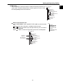
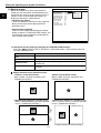
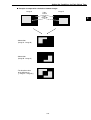
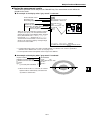
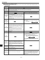
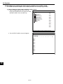
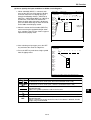
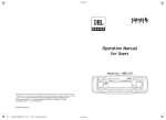
1-3 Description of the Operation screen
When the IV-C35M is started, the operation screen shown below will appear.
Each area of the operation screen is described below.
1 Object type number
7 Measuring time
2 Color mode
3 Freeze/through screen
4 Camera currently selected
COLOR F C1 BRT
(TYPE00)
5 Image brightness: bright/dark
V*.**
MEAS 0000ms 2001-10-14 10:38 MEASURE 0 CAM1 NO
6 Software version
8 Measurement
setting details
0 READY output
9 I/O relay
q Menu display
X0~7□□□□□□□□ Y0~7□□□□□□□□ READY■
MNU-CHG MAIN-COND CHG-MEA COND-CHG CHGN-REG SCREEN-CHG CHGTYPE
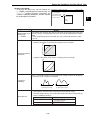
Displays the number of the currently selected object. (Object number scan ranges from 00 to 31.)
Indicates whether the current captured image is in color mode or monochrome mode.
Screen display
COLOR
No indication
Description
Appears when "color" is selected on the camera selection
Appears when "monochrome" is selected on the camera selection
Select whether to display captured images on the screen as freeze images or through images.
Display
method
Through
image
Freeze
image
Description
- Displays the stream of images captured by the camera.
- Used for adjusting the camera focus and image properties.
- Displays the single image captured at the start of making measurements.
- Used to set each of the measurement conditions and operating conditions.
To switch the image between "Through" and "Freeze" modes, press the SEL key on the remote
keypad, and then press the up and down arrow keys.
Indicates which camera is currently selected
C1: Camera 1 (the camera connected to the "CAMERA1" connector)
C2: Camera 2 (the camera connected to the "CAMERA2" connector)
1-10
Setting and Operating Outline
The brightness of the captured image can be set to one of two levels.
Screen
display
Description
BRT
Display the captured image without changing its brightness.
DRK
Display the captured image at 1/2 the actual brightness
How to select the brightness level
On any screen, except the operation screen, move the cursor to the "F" (freeze) or "T" (through)
position on the upper part of the screen by pressing the SEL key. Then, press the left or right arrow key
to move the cursor to the "BRT" (bright) or "DRK" (dark) indicator. Press the up or down arrow key to
switch between bright and dark.
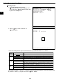
Displays the software version.
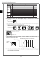
Displays the measurement time currently assigned.
Actual measurement time
(Only when changing the object type)
Time to change
object type
CCD exposure time
(Shutter operation time)
CCD image
capture time
Image
processing time
Result output
time
- Serial communication time is not included.
- Set the controller as follows to reduce the measurement time.
1. Increase the shutter speed.
2. Select the "partial" image capture feature for the CCD.
3. Select "NO" for the measurement results display (message display, pattern display, and binary
image display).
Display setting details of each measurement.
MEASURE 0
CAM1
NO
↑
Measurement
numbers from 0 to 4
↑
Camera 1 or
camera 2
↑
Measurement
program name
Displays the status of input relays X0 to X7: OFF [
], ON [
].
Displays the status of output relays Y0 to Y7: OFF [
], ON [
].
Displays the status of the ready output: OFF [
], ON [
].
The menu bar at the bottom has two rows. When this menu is selected, the second row will appear.
MNU-CHG MAIN-COND CHG-MEA COND-CHG CHNG-REG SCREEN-CHG CHG-TYPE
MNU-CHG NEXT-NG CHG-C1 CHG-C2 MANL-MEAS SHORTCUT
The details of each item on this menu bar are shown on the next page.
1-11
1
Setting and Operating Outline
1
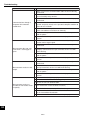
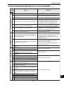
Details of each item on the menu bar
Item on the menu bar
Description
Display detail on the screen
IVC35M
MAIN-COND
(main conditions)
SYS-CND
OBJECT TYPE COND
SET WIZARD
EDIT MAIN OPS MENU
OPTION
ENVIRONMENT SETTING
MEMORY CARD
Displays the MAIN screen.
Press the up and down arrow keys to change the display of
the evaluation results for each measurement number.
CHG-MEA
(Measurement 0 camera 1 -> measurement 0 camera 2 ->
(Change measurement)
Measurement 1 -> Measurement 2 -> Measurement 3 ->
Measurement 4)
COND-CHG
(Change the
measurement
conditions)
CHNG-REG
(change registration)
Displays the condition change selection list. Change the
conditions that get displayed by pressing the up and down
arrow keys.
This part changes.
MEA-CND
DST&ANG COND...
NUMERIC CALC
COND-CHG CHNG-REG
Change the display of the set of stored details between [A00]
to [A07] and [A08] to [A15] using the up and down arrow keys
Displays the screen change selection list. Select a screen
using the up and down arrow keys.
Note: The OPS-MAIN, JDG-COND-CHG,and PC-MNTR do
not appear on the popup menu unless "YES" is selected.
for each corresponding item on "TYPE RUN COND"
SCREEN-CHG
menu. Only the currently available screens are listed.
(change screen)
When an NG image is stored, "NG-IMG-DISP" can be
selected. Press the SET key and the monitor will change to
the NG image display screen.
- See page 1-22 in this manual
Displays the object type selection list.
CHG-TYPE
Select an object type by pressing the up and down keys.
(change the object
This is enabled when Manual Object Type Change is set to
type)
"YES."
NEXT-NG *
List the NG screens that can be selected.
(change the NG image) Select a screen using the up and down keys.
Moves the image from Camera 1 up and down the screen
CHG-C1
using the up and down arrow keys.
(change the Camera 1 Note: This is enabled when "CAM1&2" or "CAM1&NG IMG" is
image position)
selected in 1MONITOR OUTPUT on the TYPE RUN
COND menu (operating conditions).
Moves the image from Camera 2 up and down the screen
CHG-C2
using the up and down arrow keys.
(change the Camera 2 Note: This is enabled when "CAM1&2" or "CAM1&NG IMG" is
image position)
selected in 1MONITOR OUTPUT on the TYPE RUN
COND (operation conditions).
Manually move the two crosshair cursors, and measure
distance between these two points, as well as coordinate
MANL-MEAS
distance on X and Y axes.
(Manual measurement) Note: Unless "MANL-MEAS" is selected on the
"qEXTENSION FUNC" line in the TYPE RUN COND
(operation conditions), this screen cannot be displayed.
SHORTCUT
MEASURE0 CAM1 NO
A0=
A08=
to
A072
to
A072
OPS-MAIN
PC-MNTR
PC-MNTR 2
SCREEN-CHG CHG-TYPE
(TYPE00)
This part changes.
MANL-MEAS
1CURSOR1-COORD MOVE(224.208)
2CURSOR2-COORD MOVE(287.271)
DIST-BETW-2PT 089.0
+
DIST-BETW-X 063.0
+
DIST-BETW-Y 063.0
1SHORTCUT1
2SHORTCUT2
3SHORTCUT3
Displays a short cut screen.
1-12
【PLACE】
NO
NO
NO
Setting and Operating Outline
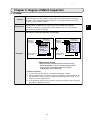
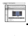
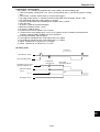
1-4 Setting the measurement programs
To execute a specific measurement program (positional deviation measurement, degree of match
inspection, etc.), select MEASUREMENT 0 to 4 on the "MEA-CND" line.
- MEASUREMENT 0 only allows you to measure positional deviation.
- For details about the settings for each measurement program, see Chapters 4 to 17.
- Specify the conditions for distance and angle measurement in the positional deviation measurement,
the degree of match inspection, object identification by binary conversion (MEAS GRAV CENTR:
YES), multiple position measurement, and for multiple degree of match inspection.
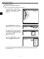
(1) Operation main screen (see page 1-10).
COLOR F C1 BRT
(TYPE00)
V*.**
MEAS 0000ms 2001-10-14 10:38 MEASURE 0 CAM1 NO
X0~7□□□□□□□□ Y0~7□□□□□□□□ READY■
MNU-CHG MAIN-COND CHG-MEA COND-CHG CHGN-REG SCREEN-CHG CHGTYPE
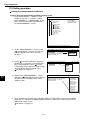
Move the cursor to the "MAIN COND" item using
the left and right arrow keys and press the SET key.
(2) Select the "OBJECT TYPE COND" using the up
and down arrow keys and press the SET key.
MAIN MENU
COLOR F C1 BRT
IVC35M
SYS-CND
OBJECT TYPE COND
SET WIZARD
EDIT MAIN OPS MENU
OPTION
ENVIRONMENT SETTING
MEMORY CARD
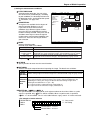
(3) Move the cursor to the "TYPE(NEW)" item on the
"OBJECT TYPE COND" line and press the SET
key.
SELECT OBJECT TYPE COND
COLOR F C1 BRT
OBJECT TYPE COND
TYPE00
TYPE(NEW)
(4) Move the cursor to "TYPE00" on the "SELECT OBJECT TYPE COND" line and press the SET key.
To select "TYPE01" and others, move the cursor to "TYPE(NEW)" and press the SET key.
(5) Select "MEAS0 to 4" (MEAS0 is only used for positional deviation measurements) on the "MEAS
COND (CAM1)" line and a popup menu will appear. Select any desired measurement program from
this popup menu and then press the SET key.
1-13
1
Setting and Operating Outline
1
1-5 Common operations for each menu
[1] Operations to return to the operation screen
You can return to the operation screen, MAIN MENU, or setting screen from any menu by a single
operation.
Menu display
When to return from the "TYPE RUN COND" menu.
F C1 BRT
SCREEN SAVE
OPS-MENU
MAIN
SELECT
RETURN
Return to the operation screen
Return to the MAIN screen.
Return to the currently selected setting screen.
Return to the previously selected screen.
[2] Saving data
All of the data such as measurement and evaluation conditions entered on the "TYPE RUN COND,"
"MEA-CND," and "SYSTEM COND" menus, can be saved into the IV-C35M flash memory.
Operation procedure
"SYS-CND" menu
SCREEN SAVE
F C1 BRT
DATA SAVE?(YES=[SET],NO=[ESC])
1. On each menu screen, move the cursor to "SAVE" using the up/down and left/right keys, and press
the SET key.
The following message will be displayed on the lower part of the screen.
DATA SAVE? (Do you want to save the data?) (YES=[SET]/NO=[ESC])
2. Press the SET key.
The IV-C35M will start saving the data and the progress will be displayed on the bottom of the screen.
SAVING
REFERENCE IMG ■■
SYSTEM I/O
■
OBJECT TYPE COND ■■■■■■■■■■■□□□□□
When the data has been saved in the IV-C35M flash memory, the display will change from "SAVING"
to "COMPLETE SAVE."
1-14
Setting and Operating Outline
1-6 Power ON setting menu
1
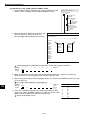
[1] Operations menu lock
To prevent accidental changes to conditions you have set, the operation screen can be locked so that the
screen cannot be changed to setting screen. The operation can only be carried out on the "POWER ON
SETTING" menu.
Display procedure
Follow the procedure described below when turning ON the power to the controller (IV-C35M), and the
"POWER ON SETTING" menu will be displayed on the monitor.
1. Turn ON the power to the IV-C35M controller, while holding down the ESC key.
2. Keep pressing the ESC key down for approx. 9 sec., after turning ON the power and the menu will
be displayed.
SEL TRG/BRT
[POWER ON SETTING]
1 MAIN OPS MENU UNLOCK LOCK
2 DISPLAY MODE JAPANESE ENGLISH
3 OPERATION
1 MAIN OPS MENU
UNLOCK
LOCK
ESC
SET
Description
All of the operating conditions for the
IV-S30 can be changed.
The MAIN OPS MENU is locked and
no change can be made.
Operation procedure
1. On the "POWER ON SETTING" menu, move the cursor to item " MAIN OPS MENU" with the up
and down keys, and press the SET key.
2. Move the cursor to "UNLOCK" or "LOCK" with the left and right keys, and press the SET key.
3. Move the cursor to item " OPERATION" with the up and down keys, and press the SET key.
Press the SET key once more.
The IV-C35M saves the settings in the flash memory and the screen will return to the operation
screen.
Display when the operation screen is locked
(TYPE00)AREA1
COLOR T.IMG C1 L
LOCK FULL VX.X
OK
MEAS XXXXms
MEASURE 0 CAM1 POSI-DEVIATION
"LOCK" will be displayed
on the MAIN OPS MENU
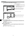
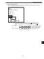
[2] Change the Japanese or English display mode
Change display between Japanese and English. Use the "POWER ON SETTING" menu for the selection.
Display procedure
Follow the procedure described below when turning ON the power to the controller (IV-C35M), and the
"POWER ON SETTING" menu will be displayed on the monitor.
1. Turn ON the power to the controller, while holding down the ESC key.
2. Keep pressing the ESC key down for approx. 9 sec., and the following menu will be displayed.
[POWER ON SETTING]
1MAIN OPS MENU
2DISPLAY MODE
3
3OPERATION
5
SEL TRG/BRT
UNLOCK LOCK
JAPANESE ENGLISH
4
ESC
SET
Operating procedure
3. Move the cursor to item " DISPLAY MODE" (display mode) with the up and down keys, and press
the SET key.
4. Move the cursor to "JAPANESE" or "ENGLISH" with the left and right keys.
5. Move the cursor to " OPERATION" using up and down keys and press the SET key. Then, again
press the SET key.
The screen will change to operation screen.
1-15
Setting and Operating Outline
1
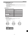
1-7 Remote keypad (IV-S30RK1)
4 SEL key
1 Direction keys
(up, down, left and right)
5 TRG/BRT key
2 SET key
3 ESC key
Key name
Direction keys*
1 (up, down, left
and right)
Function
Description
Selecting an item on a
menu screen
Select an item with the up, down, left and right
keys.
Setting a window
Set each coordinate.
Setting a value
- Select a digit or an item with the left and right
keys, and then specify a value with the up and
down keys.
- Specify a value with the up, down, right and
left keys.
To enter nested menus
2 SET key
3 ESC key
4 SEL key
Determine a highlighted
item
Determine the setting
value
Returning a setting to its On the REG-COND screen,
original state before be- - Press the left arrow key + ESC key to change
ing changed
between a display of all items and just one
Returning to the previous item at a time.
menu
- When the screen is changed from "Through"
to "Freeze," the IV-S30 will capture an image.
Use to select the display
- Change the brightness of the image displayed
of object images:
on the screen.
choose between "F"
On the setting screen,
(Freeze) and "T"
(Through) and between - Press the left arrow key and the SEL key to
change between Through and Freeze.
"BRT" (bright) and
- Press the right arrow key and the SEL key to
"DRK" (dark).
change between Bright and Dark.
Start measurement input
5 TRG/BRT key
Press this key on the run screen, and a new
measurement is triggered.
Move the cursor to the
function menu at the
upper area.
Displays popup menu.
* The direction keys have an auto-repeat function.
1-16
Setting and Operating Outline
1-8 Register and display NG images
NG image refers to any image that the controller has determined to be unacceptable after making the
measurements.
- NG images are registered in the controller’s memory. By replaying the NG images, you can review the
points with problems.
This section describes how to register, display, and initialize NG images.
Item
Reference page
Register NG images
1-17
Display when
MAIN OPS
an NG image 1-19 to 1-21
NG images menu
occurs
screen
display
Display history 1-21
NG image display screen 1-22
Initialize NG images
1-23
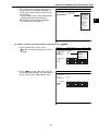
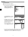
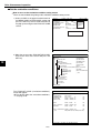
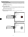
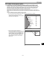
[1] How to register NG images
When the IV-C35M is used, select "YES" for NG image registration. NG images will be registered in the
controller’s memory as they occur.
To make this setting, select " REGST NG IMG" on the [OBJ-TYPE SYS.] menu.
See page 3-52.
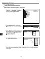
NG screen setting procedure
On the "SELECT OBJECT TYPE COND" screen,
select "MEA-CND (CAMERA2)" and press the TRG/
BRT key. From the popup menu, select "NG IMGS"
and press the SET key.
SELECT OBJECT TYPE COND
OBJECT TYPE COND
TYPE00
TYPE RUN COND
IMAGE-ADJ
MEA-CND(CAMERA1)
+ MEA-CND(CAMERA2)
FINAL NUM. CALC
FINAL OUTPUT COND
OBJ-TYPE I/0
OBJ-TYPE SYS.
TYPE(NEW)
COLOR F C1 BRT
OPS-MENU
SAVE
NG IMGS
SET=TO NEXT SUB-MENU ESC=BACK SEL=CHNG IMG TRG=POPUP
When the message shown on the right appears,
press the SET key.
BY CHANGING A SETUP, THE CONTENTS OF SETTING IN A
CAMERA 2 WILL BE INITIALIZED. DO YOU CHANGE IT?
YES=SET, NO=ESC
1-17
1
Setting and Operating Outline
1
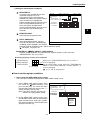
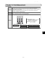
The "MEA-CND (CAMERA2)" item will change to
"MEA-CND (NG IMGS)," and show that the NG
image function has been selected.
Up to 128 NG images can be registered at one
time (the NG image numbers are 0 to 127). When
128 NG images are registered, the oldest NG
image will be deleted and replaced by the 129th
NG image. (All of numbers assigned to the NG
images will de decrement by one.)
The actual total number of NG images that can be
registered may less than the 128, depending on
the size of the images registered.
SELECT OBJECT TYPE COND
COLOR F C1 BRT
OBJECT TYPE COND
TYPE00
TYPE RUN COND
IMAGE-ADJ
MEA-CND(CAMERA1)
MEAS0 (POSI-DEVIATION)
POSI-CORRECT
MEAS(NEW)
MEA-CND(NG IMGS)
FINAL NUM. CALC
FINAL OUTPUT COND
OBJ-TYPE I/0
OBJ-TYPE SYS.
TYPE(NEW)
SET=TO NEXT SUB-MENU ESC=BACK SEL=CHNG IMG TRG=POPUP
[Limitation] The total number of NG images sizes can only occupy a maximum 8, full-size screens
(1,966,080 pixels: 512 x 480 x 8). The maximum screen size is 512 x 480 pixels.
Example: When the NG image size is 256 x 240 pixels, the controller can register up to 32
images. (256 x 240 x 32 = 1,966,080)
1-18
Setting and Operating Outline
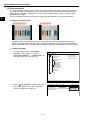
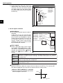
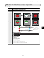
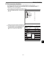
[2] How to display NG images
NG images can be displayed on the operation main screen and on the NG image display screen .
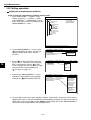
(1) Displaying NG images on the MAIN OPS menu
An NG image (the latest or any previous NG image) recorded with camera 1 can be displayed on the
monitor while conducting measurements from the operation main screen.
- This function only refreshes the NG image if another NG is captured. The screen is not refreshed
with normal image measurement results. Thus, this method is useful for an operation that has a
short cycle time and needs to process another workpiece soon after saving the NG image.
- When the measuring is stopped, NG images can also be displayed on the NG image display
screen.
See page 1-22.
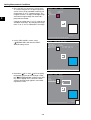
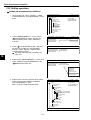
The setting procedures are as follows:
1. Select "CAM1&NG-IMG" from the monitor
output.
See page 1-17 to 1-18.
TYPE RUN COND SCREEN SAVE
2. Set the monitor output to "NG-IMGS" or
"CAM1&NG-IMG."
Select " MONITOR OUTPUT" on the "TYPE
RUN COND" menu.
1MONITOR OUTPUT
2CAPTUR IMG
3MESSAGE DISPLAY
4PATTERN DISPLAY
5SHOW BINARY
6SHOW θFIX IMG 7OPS MAIN DISP
8DISP CHG-EVAL
9PC-MNTR
0THROUGH DISPLAY
qEXTENSION FUNC.
NG INGS
PARTIAL-IMG
YES(NUMERIC)
YES
YES
YES
YES
NO
NO
NO
NO
COLOR F C1 BRT
CAM1
NG IMGS
CAM1&NG-IMG(HORIZ)
CAM1&NG-IMG(VERT)
SET=SELECT A MENU ESC=BACK SEL=CHNG IMG TRG=FUNC
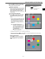
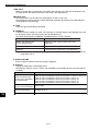
Description
①MONITOR OUTPUT
CAM1
Display the camera 1 image on the whole screen.
NG-IMGS
Display the NG image on the whole screen.
CAM1&NG-IMG (HORIZ)
Display the camera 1 image on upper half, and the NG image on lower half.
CAM1&NG-IMG (VERT)
Display the camera 1 image on left half, and the NG image on right half.
1-19
1
Setting and Operating Outline
1
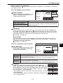
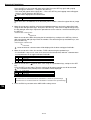
3. Return to the operation main screen (page 1-10) and start making measurements.
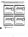
Shown below are examples of the NG image display.
- Display example when the monitor output is
set to "CAM1&NG-IMG (VERT)."
- Display example when the monitor output is
set to "CAM1&NG-IMG (HORIZ)."
(TYPE00)
(TYPE00)
COLOR CH BRT
V*.**
COLOR CV BRT
V*.**
Display
camera1
measured
image
Display
camera1
NG image
MNU-CHG MAIN-COND CHG-MEA COND-CHG CHNG-REG SCREEN-CHG CHG-TYPE
MNU-CHG MAIN-COND CHG-MEA COND-CHG CHNG-REG SCREEN-CHG CHG-TYPE
Display camera1 Display camera1 NG
measured image image
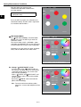
- Display example when the monitor output is set
to "NG-IMG."
(TYPE00)
COLOR C2 BRT
V*.**
Display
camera1
NG image
MNU-CHG MAIN-COND CHG-MEA COND-CHG CHNG-REG SCREEN-CHG CHG-TYPE
1-20
Setting and Operating Outline
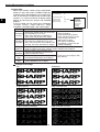
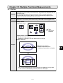
Display when an NG image is captured
The controller automatically refreshes the NG image each time a new NG image is captured.
[An example of the split screen display (above and below)]
OK4 image
NG6 image
OK7 image
Measured
image from
Camera 1
NG image
from
Camera 1
NG2 image
Camera 1
capturing
image
OK1
NG2
OK3
Refreshes to NG6 image
OK4
OK5
NG6
OK7
OK9
NG6
NG2
Camera 1
NG image
OK8
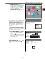
Display history of NG images
Move the cursor to the menu bar "SCREEN-CHG" on the operation main screen, using the left and right
key. Select the "NG-IMG-DISP" from the popup menu to display previous NG images.
[An example of scrolling the split screen display (above and below)]
Measured
image from
camera 1
Up key
Display NG
image
history
Up key
Down key
Down key
NG image number 9
NG image number 10
NG image number 0
- When a maximum of 10 NG images is registered.
When a new NG image is captured while displaying the history, it will be added to the history.
Note
- When "PARTIAL-IMG" is selected for image capturing (page 2-4), the NG images stored
have the maximum rectangular area set in measurements 0 to 4.
- When "CAM1&NG-IMG" is selected for the monitor output, only one camera* can be used
for each measurement (0 to 4) and for image pre-processing.
* The camera connected to the camera 1 connector (CAMERA 1).
1-21
1
Setting and Operating Outline
1
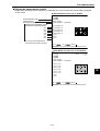
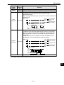
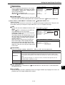
(2) Displaying images on the NG image display screen
When the IV-C35M is used, move the cursor to the menu bar "SCREEN-CHG" on the operation main
screen (page 1-10) and press the SET key. Select the "NG-IMG-DISP" from popup menu. The screen
will change to the NG image display. When the measurement stops, the NG image will be displayed.
- To display NG images while measuring, display them on the operation main screen.
Note: Please be aware of the following.
1. Change the image display mode in the upper right of the screen to "F" (freeze image) by
pressing the SET key.
2. You cannot measure objects while an NG image is being displayed on the NG image
display screen.
4
Display the NG image number and
the number of NG images that
have been registered.
The NG image number can be
selected by selecting "NEXT-NG"
on the menu bar.
Displays the date and time the NG
image was captured.
Example: 2000-10-01 10:25
October 1st, 2000, AM
10:25.
COLOR F
(TYPE00)
OK
MEAS ××××ms 2001-10-14 10:38
MEASURE 0 CAM1 POSI-DEVIATION
CH DRK ○
V*.**
1
NG-IMG 0 (1P)
2001-11-01 10:25
2
*2
X:360 Y:350
X0~7□□□□□□□□ Y0~7□□□□□□□□ READY■
MNU-CHG CHG-MEA COND-CHG CHNG-REG NEXT-NG RE-EXAM DEL NG
3
Displayed when the menu is changed.
MNU-CHG OPS-MENU DEL ALL NG
Menu bar
Menu bar
Details
Change the evaluation result display for the measurement
CHG-MEA
numbers using the up and down keys.
(change measurement) (MEASURE0 CAM1 -> MEASURE0 CAM2 -> MEASUREMENT1 ->
MEASUREMENT2 -> MEASUREMENT3 -> MEASUREMENT4 ->)
Change the operation menu using the up and down keys. "Display NG
image" -> change evaluation conditions
- The operating screen display must be set to "YES."
COND-CHG
- See page 2-9.
(change measurement
- For information about the evaluation condition change screen,
condition)
see page 2-11.
- On the evaluation condition change screen, press the SET key.
The cursor will move to the setting change screen.
CHNG-REG
Change the measurement result display of the registered numbers in
(change register)
the measurement program using the up and down keys.
NEXT-NG
Change the registered number for the NG image being displayed
(change NG image) using the up and down keys. - See the next page.
RE-EXAM
Replay the measurements made on the NG image selected with
(replay)
"NEXT-NG", by pressing the SET key.
DEL NG
Press the SET key. Only the NG image selected with "NEXT-NG" will
(delete NG image) be deleted.
DEL ALL N (delete all
Press the SET key. All the registered NG images will be deleted.
NG images)
OPS-MENU
Press the SET key, the screen will return to the operation main screen.
When "CAM1&2" is selected on the " MONITOR OUTPUT" line (TYPE RUN COND
menu), the camera numbers (CH) will be displayed on the screen next to the images from
those cameras.
1-22
Setting and Operating Outline
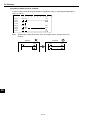
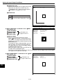
Display of the Change NG image operation
1
Up key
Up key
Down key
Down key
NG image number
4
NG image number
5
NG image number
0
- When max. 5 NG images are registered.
Note
- When "PARTIAL-IMG" is selected for the image capturing mode (page 2-4), the stored NG images
have the maximum rectangular area set by measurements 0 to 4.
[3] Initializing the NG images
NG images can be initialized with any of the following methods:
1. Item " INITIALIZATION", on the "OPTION" menu, will execute an "NG-IMG-INIT".
Page 2-20.
2. Execute a "DEL NG" (delete NG image) or "DEL ALL N" (delete all NG images) on the menu bar of
the NG image display screen.
See the previous page.
3. When the object type number is changed, the registered NG images are initialized.
1-23
Setting and Operating Outline
1
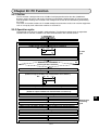
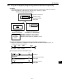
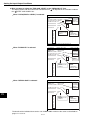
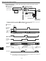
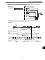
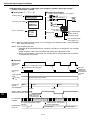
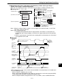
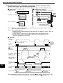
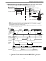
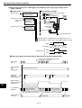
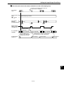
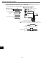
1-9 Operation flow
[1] Power ON and main loop processing
(Power ON)
Wait to complete the power ON process
Initializing (CPU, gate array)
Memory check
- System program
- Conditions other than
the conditions specified
for each object type
Transmitting from flash memory to RAM
Data setting
- CPU, variables
- Gate array
Checksum checking
NG
Processing after the
power is turned ON
OK
Display check sum results
No
Settings for all types completed
Yes
Transmitting from flash memory to RAM
Measurement conditions for
each object type
Obtaining images, capturing
specific lines of an image
ESC key
OFF
ON
Place the operation screen
in the locked state
To the next page
1-24
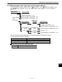
Setting and Operating Outline
1
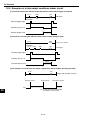
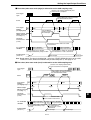
From the preceding page
Display results.
When the option has been set to "YES"
Message display
Pattern display
Crosshair cursor display
(Communication processing)
Data received
(System) Display "YES"
No
Yes
Communication processing
Receive a measurement
start input signal
Measurement start
Parallel/general-purpose serial/CCD
trigger
OFF
Main loop
processing
ON
PC calculation
PC calculation
See item [2].
Executing measurements
Measurement result output processing
Key input
Parallel/general-purpose serial
No
Yes
Process key strokes
Processing on sub-menu
(Menu configuration
See page
1-4.)
1-25
Setting and Operating Outline
1
[2] Operation flow after the measurement start input is turned ON.
Start (measurement start input ON)
PC calculation
Parallel output (Y0 to Y15), "READY" OFF
External interface inhibit
(keys, communications, parallel)
Measurement timer start
Reading the object type No.
Image capturing (camera 1/2)
No
Capture the scan line range that was
specified when setting the
measurement conditions.
*1 The measurement start input is
set to "PARALLEL" and the
’READY’ ON signal to "end of
image capture."
*1
Yes
READY ON
No
Is the light level
monitor selected?
Yes
Execute the light level
monitor function
Executing measurement 0 using
camera 1
Yes
[Measurement program that is
selected]
- Positional deviation measurement
Was an error detected?
No
Executing measurement 0 using
camera 2
Yes
Was an error detected?
No
2 (To the next page)
1 (To the next page)
1-26
Setting and Operating Outline
1
2 (From the preceding page) 1 (From the preceding page)
No
Positional correction
Yes
Setting the coordinate correction
values (X, Y, q)
(*2)
Executing measurement 1
Yes
Was an error detected?
No
Executing measurement 2
Yes
Was an error detected?
The window coordinates are
corrected within the range set for
each type of measurement,
based on the correction value
determined in the steps marked with
*2.
No
Executing measurement 3
Yes
[Measurement programs that can be
selected]
- Positional deviation measurement
- Degree of match inspection
- Lead inspection
- BGA/CSP inspection
- Area measurement by binary
conversion
- Counting by binary conversion
- Object identification by binary
conversion
- Color evaluation
- Color unevenness inspection
- Color positional measurement
- Point measurement
- Multiple positional measurements
- Multiple degree of match inspection
- Fault inspection
Was an error detected?
No
Executing measurement 4
Yes
Was an error detected?
No
No
PC calculation
Message display
Yes
No
Error display
Message display
Yes
Displaying the measurement results
(values, decisions etc.)
No
Pattern display
Yes
Positional correction yes
No
Yes
Display pattern after correction Display pattern when setting
To the next page
1-27
Setting and Operating Outline
1
From the previous page
Determining the measuring time (timer stop)
Parallel output (Y0 to Y15) OFF
External interface enabled (communications)
No
Computer link
Serial output
General purpose
General purpose serial output
Computer link output
External interface enabled (key, parallel)
*3 Set the measurement
start input to any choiceNo
other than "parallel" or
set the ’READY’ ON
signal to "end
measurement."
*3
Yes
READY ON
Waiting for a measurement start input signal or a key input
- When the stop NG measurement option is set to "YES" (page 3-53), the controller stops measuring
when an error occurs.
1-28
Setting and Operating Outline
1-10 Table of controller functions
Shown below are the functions for the individual controllers (IV-C35M).
- For details about the controller hardware (cameras, peripheral devices), see the "IV-C35M User’s
Manual, Instruction and Hardware."
Item
Image sampling system
Number of pixels
Image memory
Specifications
16,770,000 colors, 256 level gray scale, binary conversion,
edge detection
512 (horizontal) x 480 (vertical), approximately 240,000
pixels.
One screen for displaying captured images. One
monochrome screen for displaying camera information and
messages
32 object types
No.of assignable object type
Maximum number of reference images
600 / 8 screens
stored / number of whole screens stored
IV-C30C5
33.3 ms
Image
16.7 ms [full mode]
scan time
IV-S30C3/C4
8.3 ms [half mode] (Variable, with partial-image capturing)
9 ms (When the search area is 256×256 pixels, the model
Gray search time
size is 64×64 pixels, and the contraction function is set to 3.)
Gray search, edge detection precision Pixel, sub-pixel
Color filter (R, G, B, brightness, custom)
Image processing
Color extraction (hue, saturation, brightness)
Gray search
Color
Hue correction
Adjust hue level
image preAdjust brightness level
processing Brightness correction
Dividing, subtracting, and filtering
Shading correction
Subtracting, absolute value of difference (between camera 1
Comparative calculation
and reference image, between camera 2 and reference
Gray
between images
image, between camera 1 and camera 2)
image preMagnification by "n" processing, g (+/-) correction, histogram
processing
Gray level changes
widening, mid-range emphasis
Smoothing (center/average), edge emphasis, edge extraction,
Space filter
horizontal edge, vertical edge
Fixed and threshold value corrections (variation
Binary threshold value
difference/variation rate)
Expansion to contraction, contraction to expansion, area filter
Binary noise elimination
Specified window (rectangle, circle, oval), any binary image
Binary image mask
mask
X/Y correction, rotation correction
Positional correction method
1-29
1
Setting and Operating Outline
Specifications
Item
Area, hue (average), saturation (average), color degree of match
[Maximum 8 windows ]
Number of objects [Maximum 128 windows ]
Color unevenness
Total area, hue (max./min.), number of faults of hue, saturation (max./min.), and
inspection
number of faults of saturation. [Maximum 4 windows ]
XY coordinate, XY deviation amount, color degree of match (1-point search, 2-point
Color position
search, 1-point edge, 2-point edge, 1-point search and 1-point edge)
measurement
[Maximum 8 windows x 2 models]
Fault inspection
Density (max./min.), density difference (max.) [Maximum 8 windows ]
XY coordinate, deviation amount in X and Y axes, degree of match (1-point search, 2Positional deviation point search, 1-point edge, 2-point edge, 1-point search and 1-point edge)
measurement
Angle: ±15 , ±30 , ±45 , 360 (1-point search, 1-point search + 1-point edge)
[Maximum 8 windows x 2 models]
Degree of match Degree of match, XY coordinate, density (1-point search, 2-point search)
inspection
[Maximum 16 windows x 2 models]
Area measurement
Area [Maximum 16 windows]
by binary conversion
Object counting by
Quantity (maximum 3,000 items per window), total area [Maximum 4 windows]
binary conversion
Quantity (maximum 128 per window), total area, area of each object identified, gravity
Object identification
center, main axis angle, fillet diameter, peripheral length, center point
by binary conversion
[Maximum 4 windows]
Point measurement Number in binary image (maximum 256 points), average density [Maximum 128 points]
Number of leads, distance between leads (max., min.), lead width (max., min.), lead
Lead inspection
length (max., min.)
[Maximum 16 windows]
Number of labels, total area, area of each label, XY pitch (max., min.) XY fillet diameter
BGA/CSP inspection
(max., min.), [Maximum 4 windows ]
Multiple positional Number of objects (max. 128), degree of match, XY coordinate (1-point search, 1-point
measurement
edge)
[Maximum 4 windows]
Multiple degree of Number of objects (max. 128), degree of match, XY coordinate (1-point search)
match inspection [Maximum 4 windows]
Maximum 6 per object type (measurement 0 - camera 1, measurement 0 - camera 2,
Number of measurement
measurements 1 to 4)
programs
Note: Measurement 0 is only used for positional deviation measurement.
Rectangle, circle, oval (when using color evaluation, color unevenness inspection, area
measurement by binary conversion, object counting by binary conversion, object
Window shape
identification by binary measurement), circumference (when using fault inspection), and
arc (when using fault inspection).
Measure distance (between two points, X coordinate, Y coordinate), measure angle (3
Distance and angle
points, 2 points against horizontal line, 2 points against vertical line), auxiliary point
measurement
(center, circle center, gravity center, line over 2 points, crossing point of two straight
lines)
Four basic operations (+, -, X, /), root, absolute value, TAN, ATAN, maximum,
Arithmetic operation
minimum, average , total.
NG image memory
Maximum 128 images (8 images for all images)
function
Possible extension when using a memory card (compact flash memory)
Memory card slot
One slot (compatible card : up to 192 MB)
Calendar/timer
Year, month, day, hour, minute
Display measuring time, light level monitor function, crosshair cursor display, change
display language between Japanese and English, Run screen lock function, setting
Other functions
menu display "yes/no", change image display (through/freeze), change image
brightness (bright/dark)
Input relays
Parallel input: 8 points (X0 to X7)
Parallel output: 8 points (Y0 to Y7)
Output relays
General-purpose serial interface, computer link: 16 points (Y0 to Y15)
Auxiliary relays
128 points (C000 to C127), special area 18 points (C110 to C127)
Timers
8 points (TM0 to TM7), timer setting range: 0.01 to 9.99 seconds (countdown timer)
Counters
8 points (CN0 to CN7), counter setting range: 000 to 999 (counts down)
Measurement program
Color evaluation
Micro PLC
section
1
1-30
External interface
Setting and Operating Outline
Item
Parallel interface
General-purpose serial
interface
Computer link
USB
Image output
Number of cameras
Connecting camera
Make settings
Terminal block
Measurement
start input
Inputs
Outputs
Internal trigger
External trigger
Number of points
Common terminal
Number of points
Common terminal
Power
Power supply
supply
terminal
Power supply voltage
Power consumption
Storage ambient temperature
Operation ambient temperature
Operation ambient humidity
Operation atmosphere
Vibration resistance
Shock resistance
Noise immunity
Outside dimensions
Weight
Specifications
Input: 8 points, Output: 9 points, 12/24 VDC
RS232C/RS422 (2.4 to 115.2 kbps)
Built-in compatibility with certain SHARP, OMRON, Mitsubishi and
Yokogawa models
USB device node (Compatible with USB1.1)
1 channel, Equivalent to NTSC system, 2:1 interlace
Maximum of 2
IV-C30C5, IV-S30C3, IV-S30C4
Using the IV-S30RK1 remote keypad and/or the IV-S30SP parameter
setting support software
Color CCD trigger, (Gray) CCD trigger
Trigger input (parallel I/F), general-purpose serial I/F, keypad trigger (for
manual measuring)
8 points: External trigger; 1 point (X0), Object type change; 5 points (X1 to
X5), external input; 2 points (X6, X7)
1 point: + or - common
9 points: 1 READY , 8 user settable logical outputs (Y0 to Y7)
1 point: + or - common
2 points: +24 VDC, 0 V
24 VDC (±10%)
12 W
-20 to 70oC
0 to 45oC
35 to 85% RH (non-condensing)
No corrosive gases or dust
JIS C 0911 or equivalent
JIS C 0912 or equivalent
1000 Vp-p 1ms width impulse (by noise simulator) when applied to the
primary side (100 VAC) of an external DC power supply
130 (W) · 100 (D) · 42 (H) mm (except protruding portions)
Approx. 600 g
1-31
1
Setting the Operating and System Conditions
Chapter 2: Setting the Operating and System Conditions
2
2-1 Setting the operating conditions
Set the following operating condition items on the "TYPE RUN COND" menu for each object type.
Item to set
Monitor output
Image capture
Message display
Pattern display
Binary image display
q angle correction image display
Operation main display
Evaluation change display
PC monitor screen
Through display
Extension function
Reference page
2-2
2-4
2-5
2-6
2-7
2-8
2-9
2-10
2-11
2-11
2-12
How to display the TYPE RUN COND screen
On the "MAIN MENU," select "OBJECT TYPE
COND", "TYPE 00", and "TYPE RUN COND" in this
order.
SELECT OBJECT TYPE COND
OBJECT TYPE COND
TYPE00
TYPE RUN COND
IMAGE-ADJ
+ MEA-CND(CAMERA1)
+ MEA-CND(CAMERA2)
FINAL NUM.CALC
FINAL OUTPUT COND
OBJ-TYPE I/O
OBJ-TYPE SYS.
TYPE(NEW)
COLOR F C1 BRT
1MONITOR OUTPUT
2CAPTURE IMG
3MESSAGE DISPLAY
4PATTERN DISPLAY
5SHOW BINARY IMG
6SHOW θFIX IMG
7OPS MAIN DESP
8DESP CHG-EVAL
9PC-MNTR
0THROUGH DISPLAY
qEXTENSION FUNC.
wDISPLAY+CURSOR 1
eCLOSS CURSOR COORD
rDISPLAY+CURSOR 2
tCLOSS CURSOR COORD
SET=TO NEXT SUB-MENU ESC=BACK SEL=CHNG IMG TRG=POPUP
The "TYPE RUN COND" screen will appear.
TYPE RUN COND SCREEN SAVE
1MONITOR OUTPUT
2CAPTURE IMG
3MESSAGE DISPLAY
4PATTERN DISPLAY
5SHOW BINARY IMG
6SHOW θ FIX IMG
7OPS MAIN DISP
8DISP CHG-EVAL
9PC-MNTR
0THROUGH DISPLAY
qEXTENSION FUNC.
COLOR F C1 BRT
CAM1
PARTIAL-IMG
YES(NUMERIC)
YES
YES
YES
YES
NO
NO
NO
NO
SET=SELECT A MENU ESC=BACK SEL=CHNG IMG TRG=FUNC
2-1
Setting the Operating and System Conditions
[1] Monitor output
1MONITOR OUTPUT
2CAPTURE IMG
3MESSAGE DISPLAY
4PATTERN DISPLAY
5SHOW BINARY IMG
6SHOW θ FIX IMG
7OPS MAIN DISP
8DISP CHG-EVAL
9PC-MNTR
0THROUGH DISPLAY
qEXTENSION FUNC.
COLOR F C1 BRT
CAM1
PARTIAL-IMG
YES(NUMERIC)
YES
YES
YES
YES
NO
NO
NO
NO
CAM1
CAM2
CAM1&2(HORIZ)
CAM1&2(VERT)
- Output monitor switching
There are two methods for changing the monitor
output: change the TYPE RUN COND settings, use
external input signals through the parallel port to
make changes from outside.
SET=SELECT A MENU ESC=BACK SEL=CHNG IMG TRG=FUNC
(1) Change the monitor output by changing the TYPE RUN COND settings
Select the " MONITOR OUTPUT" item on the "TYPE RUN COND" screen and then select an
item from the popup menu.
1MONITOR OUTPUT
Description
CAM1
CAM2
Display the camera 1 image on the whole screen.
CAM1&2(HORIZ)
Display the camera 1 image on upper half, and the camera 2 image
on lower half.
Display the camera 1 image on left half, and the camera 2 image on
right half.*
Display the camera 2 image on the whole screen.
CAM1&2(VERT)
Display examples on the operation screen
- Camera 1 on the whole screen
(When "CAM1" has been specified in item
1MONITOR OUTPUT.)
- Camera 2 on the whole screen.
(When "CAM2" has been specified in item
1MONITOR OUTPUT.)
COLOR F C2 H
COLOR F C1 H
SERIAL NO.
8F053G26
MODEL
IV-C35M
COLOR F CH H
SERIAL NO.
8F053G26
MODEL
IV-C35M
- Simultaneous display on a divided screen
(When "CAM1&2 (VERT)" has been specified
in item "1MONITOR OUTPUT.")
COLOR F CV H
Camera 2
image
- Simultaneous display on a divided screen
(When "CAM1&2(HORIZ)" has been specified
in item "1MONITOR OUTPUT.")
Camera 1
image
2
TYPE RUN COND SCREEN SAVE
When two cameras have been connected to IVC35M, you can switch back and forth between the
image from the cameras on one monitor. Also, the
monitor screen can be divided into two parts to
display the two images simultaneously.
- Purpose of the setting
To set the conditions in which an image captured
during measurement will be displayed on the
operation screen.
SERIAL NO.
8F053G26
MODEL
IV-C35M
Camera 1 image
2-2
Camera 2 image
Setting the Operating and System Conditions
(2) Output monitor switching by parallel input
On the operation screen, select "MAIN-COND" ->
"SYS-CND" -> "I/O CONDITIONS" in that order.
Move the cursor to the " PARALLEL INP X7"
line using up/down arrow keys and press the SET
key. Select "CHNG-IMG-OUT-CAM" on the popup
menu that is displayed and then press the SET
key.
I/O CONDITION SCREEN COND SAVE
1MEAS INP I/F
COLOR F C1 BRT
PARALLEL+SERIAL+USB
2OUT I/F(PARAL.) NO
3MANL TYPE CHNG NO
4PARALLEL INP X6 EXT-INP
5PARALLEL INP X7 CHNG-IMG-OUT-CAM
6STROBE OUT
NO
7’READY’ON
CAPTURE COMPLETE
2
EXT-INP
CHNG-IMG-OUT-CAM
CAM-MEAS
Every time the X7 signal is turned from OFF to
ON, the selected camera display will be changed.
CAM1
whole screen
CAM2
whole screen
CAM1&2(HORIZ)
divided screen
*CAM1&2(VERT) divided screen
The display example of the operation screen is
the same as in section (1).
2-3
SET=SELECT A MENU ESC=BACK SEL=CHNG IMG TRG=FUNC
Setting the Operating and System Conditions
[2] Image capture
2
TYPE RUN COND SCREEN SAVE
In item " CAPTURE IMG" on the "TYPE RUN
COND" screen, specify the range which will be
captured during operation.
2CAPTURE IMG
1MONITOR OUTPUT
2CAPTURE IMG
3MESSAGE DISPLAY
4PATTERN DISPLAY
5SHOW BINARY IMG
6SHOW θ FIX IMG
7OPS MAIN DISP
8DISP CHG-EVAL
9PC-MNTR
0THROUGH DISPLAY
qEXTENSION FUNC.
CAM1
PARTIAL-IMG
YES(NUMERIC)
YES
YES
YES
YES
NO
NO
NO
NO
COLOR F C1 BRT
PARTIAL-IMG
WHOLE-IMG
NO
Description
- An image of the specified lines, required for inspection or measurement,
will be captured.
- The processing time is shorter than in the "WHOLE-IMG" mode.
PARTIAL-IMG
(partial image)
WHOLE-IMG
(whole image)
- A whole image will be captured, irrespective of the window settings for
inspection or measurement.
- This mode is used to monitor portions of an image outside the window
set up for inspection or measurement
NO
(no image)
- No image will be captured during operation. Measurements will be
carried out with an image being displayed.
- This mode only used to carry out measurements on an image
transmitted from a personal computer to the IV-C35M.
Example of a comparison of the capture times
- When "WHOLE-IMG" is selected
IV-C35M
Capture whole image
16.7 ms (high-speed camera and full mode)
8.3 ms (high-speed camera and half mode)
33.3 ms (color camera)
480 lines
- Image capture mode (full/half mode)
- See page 2-18.
- When the "PARTIAL-IMG" is selected (when there are 240 scan lines)
IV-C35M
8.3 ms (high-speed camera and full mode)*
4.2 ms (high-speed camera and half mode)*
12.5 ms (high-speed camera and full + half mode)*
16.6 ms (color camera)
Capture partial image
* The image capture time may vary with the
position of the partial image. (In the following
case, maximum 0.4 ms)
240 lines
2-4
Setting the Operating and System Conditions
[3] Message display
TYPE RUN COND SCREEN SAVE
Select "YES" or "NO" to display messages on the
operation screen.
MESSAGE
DISPLAY
YES (NUMERIC)
1MONITOR OUTPUT
2CAPTURE IMG
3MESSAGE DISPLAY
4PATTERN DISPLAY
5SHOW BINARY IMG
6SHOW θ FIX IMG
7OPS MAIN DISP
8DISP CHG-EVAL
9PC-MNTR
0THROUGH DISPLAY
qEXTENSION FUNC.
Description
All data will be displayed.
YES (NO NUMERIC) Data other than the numerical
result will not be displayed.
No messages will be displayed.
NO
CAM1
PARTIAL-IMG
YES(NUMERIC)
YES
YES
YES
YES
NO
NO
NO
NO
COLOR F C1 BRT
YES(NUMERIC)
YES(NO NUMERIC)
NO
Setting to "NO" reduces the processing time.
Processing time:
YES(NUMERIC) > YES(NO NUMERIC) > NO
SET=SELECT A MENU ESC=BACK SEL=CHNG IMG TRG=FUNC
Display examples
- When "YES(NUMERIC)" is selected
(TYPE00)AREA1
OK
- When "YES(NO NUMERIC)" is selected
COLOR F C1 DRK
V*.**
(TYPE00)AREA1
OK
MEAS XXXXms XXXX-XX-XX XX:XX
MEASURE 0 CAM1 POSI-DEVIATION
COLOR F C1 DRK
V*.**
MEAS XXXXms XXXX-XX-XX XX:XX
MEASURE 0 CAM1 POSI-DEVIATION
REGST.NO 0(0~7)
X0=176.0
OK
Y0=322.0
OK
x0=+000.0
OK
y0=+000.0
OK
M0=+10000
OK
B0=+001.7
OK
X1=534.0
OK
Y1=480.0
OK
x1=+001.0
OK
y1=+001.0
OK
M1=+09999
OK
X0~7
Y0~7
READY
MNU-CHG MAIN-COND CHG-MEA COND-CHG CHNG-REG SCREEN-CHG CHG-TYPE
X0~7
Y0~7
READY
MNU-CHG MAIN-COND CHG-MEA COND-CHG CHNG-REG SCREEN-CHG CHG-TYPE
Can be deleted by pressing the SET key.
- When "NO" is selected
Press the
SET key
Press the
ESC key
X0~7
Y0~7
READY
MNU-CHG MAIN-COND CHG-MEA COND-CHG CHNG-REG SCREEN-CHG CHG-TYPE
The menu bar will disappear.
The menu bar will be displayed.
2-5
2
Setting the Operating and System Conditions
[4] Pattern display
2
TYPE RUN COND SCREEN SAVE
Select "YES" or "NO" to determine whether to show
the pattern display (solid lines and dashed lines of the
rectangles in the window) over an image displayed on
the operation screen.
Note: When the "CAM1&2(HORIZ/VERT)" or "CAM1&
NG IMG(HORIZ/VERT)" is selected on the
" MONITOR OUTPUT" (page 2-2), pattern
display cannot be selected.
PATTERN
DISPLAY
YES
NO
1MONITOR OUTPUT
2CAPTURE IMG
3MESSAGE DISPLAY
4PATTERN DISPLAY
5SHOW BINARY IMG
6SHOW θ FIX IMG
7OPS MAIN DISP
8DISP CHG-EVAL
9PC-MNTR
0THROUGH DISPLAY
qEXTENSION FUNC.
CAM1
PARTIAL-IMG
YES(NUMERIC)
YES
YES
YES
YES
NO
NO
NO
NO
COLOR F C1 BRT
YES
NO
Description
Displays patterns in the window, such
as the rectangles defined for the
inspection area and the search area.
Patterns will not be displayed
on the operation screen.
SET=SELECT A MENU ESC=BACK SEL=CHNG IMG TRG=FUNC
Display examples
- When "NO" is selected for PATTERN DISPLAY
- When "YES" is selected for PATTERN DISPLAY.
(TYPE00)
OK
COLOR F C1 DRK
VX.XX
MEAS XXXXms XXXX-XX-XX XX:XX
MEASURE 0 CAM1 POSI-DEVIATION
(TYPE00)
OK
COLOR F C1 DRK
VX.XX
MEAS XXXXms XXXX-XX-XX XX:XX
MEASURE 0 CAM1 POSI-DEVIATION
REGST. NO. 0(0~7)
X0=176.0
OK
Y0=322.0
OK
x0=+000.0
OK
y0=+000.0
OK
M0=+10000
OK
B0=+001.7
OK
X1=534.0
OK
Y1=480.0
OK
x1=+001.0
OK
y1=+001.0
OK
M1=+09999
OK
REGST. NO. 0(0~7)
X0=176.0
OK
Y0=322.0
OK
x0=+000.0
OK
y0=+000.0
OK
M0=+10000
OK
B0=+001.7
OK
X1=534.0
OK
Y1=480.0
OK
x1=+001.0
OK
y1=+001.0
OK
M1=+09999
OK
X0~7
Y0~7
READY
MNU-CHG MAIN-COND CHG-MEA COND-CHG CHNG-REG SCREEN-CHG CHG-TYPE
2-6
X0~7
Y0~7
READY
MNU-CHG MAIN-COND CHG-MEA COND-CHG CHNG-REG SCREEN-CHG CHG-TYPE
Setting the Operating and System Conditions
[5] Binary image display
TYPE RUN COND SCREEN SAVE
Select "YES" or "NO" to display a binary image on the
operation screen.
Note: When "CAM1&2(HORIZ/VERT)" or "CAM1&NG
IMG(HORIZ/VERT) is selected on the
"MONITOR OUTPUT" (page 2-2), the binary
image display cannot be selected.
- When "NO" is selected on the " PATTERN
DISPLAY," the " SHOW BINARY IMG" item will
not appear.
SHOW BINARY
IMG
1MONITOR OUTPUT
2CAPTURE IMG
3MESSAGE DISPLAY
4PATTERN DISPLAY
5SHOW BINARY IMG
6SHOW θ FIX IMG
7OPS MAIN DISP
8DISP CHG-EVAL
9PC-MNTR
0THROUGH DISPLAY
qEXTENSION FUNC.
COLOR F C1 BRT
CAM1
PARTIAL-IMG
YES(NUMERIC)
YES
YES
YES
NO
YES
YES
NO
NO
NO
NO
2
Description
YES
A binary image will be displayed on
the operation screen.
NO
A binary image will not be displayed
on the operation screen.
SET=SELECT A MENU ESC=BACK SEL=CHNG IMG TRG=FUNC
Display examples
- When "YES" is selected for the "5SHOW BINARY IMG"
(TYPE00)
(TYPE00)
COLOR F C1 DRK
VX.XX
OK
- When "NO" is selected for the "5SHOW BINARY IMG"
COLOR F C1 DRK
VX.XX
OK
MEAS XXXXms XXXX-XX-XX XX:XX
MEASUREMENT1 CNT-BIN-OBJ
MEAS XXXXms XXXX-XX-XX XX:XX
MEASUREMENT1 CNT-BIN-OBJ
K0=00006
A0=015781
K1=00020
A1=087620
K2=00010
A2=042680
K3=
A3=
K0=00006
A0=015781
K1=00020
A1=087620
K2=00010
A2=042680
K3=
A3=
OK
OK
OK
OK
OK
OK
X0∼7
Y0∼7
READY
MNU-CHG MAIN-COND CHG-MEA COND-CHG CHNG-REG SCREEN-CHG CHG-TYPE
OK
OK
OK
OK
OK
OK
X0∼7
Y0∼7
READY
MNU-CHG MAIN-COND CHG-MEA COND-CHG CHNG-REG SCREEN-CHG CHG-TYPE
2-7
Setting the Operating and System Conditions
[6] θ angle correction image display
TYPE RUN COND SCREEN SAVE
Select "YES" or "NO" to display a θ angle corrected
image on the operation screen.
2
SHOW
FIX q IMG
YES
NO
Description
A q angle corrected image will be
displayed on the operation screen.
A q angle corrected image will not be
displayed on the operation screen.
1MONITOR OUTPUT
2CAPTURE IMG
3MESSAGE DISPLAY
4PATTERN DISPLAY
5SHOW BINARY IMG
6SHOW θ FIX IMG
7OPS MAIN DISP
8DISP CHG-EVAL
9PC-MNTR
0THROUGH DISPLAY
qEXTENSION FUNC.
COLOR F C1 BRT
CAM1
PARTIAL-IMG
YES(NUMERIC)
YES
YES
YES
YES
NO
YES
NO
NO
NO
NO
SET=SELECT A MENU ESC=BACK SEL=CHNG IMG TRG=FUNC
Display examples
(Reference image)
(Measured image)
Position of
reference image
- When the q angle correction
image display mode has
been set to YES.
- When the q angle correction
image display mode has
been set to NO.
2-8
Setting the Operating and System Conditions
[7] Operation main display
When the operation screen was set to display other
screens (such as the "DISP CHG-EVAL" and "PCMNTR" screens), this item should be selected to
return to the main display from other screens. On the
"TYPE RUN COND" screen, select " OPS MAIN
DISP" and then "YES" on the popup menu. That will
return you to the main operation screen.
Note: When other screens are set to "YES" (such as
the " DISP CHG-EVAL" and " PC-MNTR"
screens), make sure to select "YES" from the
OPS MAIN DISP.
TYPE RUN COND SCREEN SAVE
1MONITOR OUTPUT
2CAPTURE IMG
3MESSAGE DISPLAY
4PATTERN DISPLAY
5SHOW BINARY IMG
6SHOW θ FIX IMG
7OPS MAIN DISP
8DISP CHG-EVAL
9PC-MNTR
0THROUGH DISPLAY
qEXTENSION FUNC.
COLOR F C1 BRT
CAM1
PARTIAL-IMG
YES(NUMERIC)
YES
YES
YES
YES
YES
NO
NO
NO
NO
NO
2
SET=SELECT A MENU ESC=BACK SEL=CHNG IMG TRG=FUNC
Press the TRG/BRT key to move the cursor to the
upper function menu. Select "SCREEN" and press
the SET key. Then select "OPS-MENU."
Select "SCREEN-CHG" on the lower menu on the
operation screen and press the SET key. "OPSMAIN" will be displayed in the lower right corner of
the screen. While the "OPS-MAIN" line is highlighted,
press the SET key. The main display will then change
back to the operation screen from the other screens
(e.g. the JDG-COND-CHG and PC-MNTR screens).
TYPE RUN COND SCREEN SAVE
1MONITOR OUTPUT
2CAPTURE IMG
3MESSAGE DISPLAY
4PATTERN DISPLAY
5SHOW BINARY IMG
6SHOW θ FIX IMG
7OPS MAIN DISP
8DISP CHG-EVAL
9PC-MNTR
0THROUGH DISPLAY
qEXTENSION FUNC.
CAM1
PARTIAL-IMG
YES(NUMERIC)
YES
YES
YES
YES
NO
NO
NO
NO
(TYPE00) AREA1
OK
MEAS XXXXms 2001-10-14 10:38
COLOR
F C1 BRT
OPS-MENU
MAIN
SELECT
RETURN
COLOR F C1 DRK○
V*.**
C1=002.2 OK
C2=100.0 OK
MEASURE 0 CAM1 POSI-DEVIATION
OPS-MAIN
PC-MNTR
PC-MNTR 2
X0∼7 □□□□□□□□ Y0∼7 □□□□□□□□ READY ■□
MNU-CHG MAIN-COND CHG-MEA COND-CHG CHNG-REG SCREEN-CHG CHG-TYPE
2-9
Setting the Operating and System Conditions
[8] Evaluation change display
2
Specify whether the evaluation condition change
menu can be displayed on the operation screen or
not.
Select the " DISP CHG-EVAL" line on the "TYPE
RUN COND" screen and select "YES" on the popup
menu.
TYPE RUN COND SCREEN SAVE
1MONITOR OUTPUT
2CAPTURE IMG
3MESSAGE DISPLAY
4PATTERN DISPLAY
5SHOW BINARY IMG
6SHOW θ FIX IMG
7OPS MAIN DISP
8DISP CHG-EVAL
9PC-MNTR
0THROUGH DISPLAY
qEXTENSION FUNC.
COLOR F C1 BRT
CAM1
PARTIAL-IMG
YES(NUMERIC)
YES
YES
YES
YES
YES
YES
NO
NO
NO
NO
SET=SELECT A MENU ESC=BACK SEL=CHNG IMG TRG=FUNC
Press the TRG/BRT key to move the cursor to the
upper function menu. Select "SCREEN" and press
the SET key. Then select "OPS-MENU."
Select "SCREEN-CHG" on the lower menu on the
operation screen, and press the SET key. "JDGCOND CHG" will be displayed in the lower right
corner of the screen. You can display the evaluation
condition change menu by pressing the up and down
keys.
- Press the SET key. The cursor will move to the
area containing the phrase "evaluation condition
change menu during operation." You can change
the settings for the evaluation conditions.
- At this time, the screen display will look the same
as the normal operation main screen, except for the
area marked "evaluation condition change menu
shown during operation."
TYPE RUN COND SCREEN SAVE
1MONITOR OUTPUT
2CAPTURE IMG
3MESSAGE DISPLAY
4PATTERN DISPLAY
5SHOW BINARY IMG
6SHOW θ FIX IMG
7OPS MAIN DISP
8DISP CHG-EVAL
9PC-MNTR
0THROUGH DISPLAY
qEXTENSION FUNC.
CAM1
PARTIAL-IMG
YES(NUMERIC)
YES
YES
YES
YES
NO
NO
NO
NO
(TYPE00)
COLOR
F C1 BRT
OPS-MENU
MAIN
SELECT
RETURN
COLOR F C1 BRT
MEAS 0000ms 2001-10-14 10:38
MEASURE 0 CAM1 POSI-DEVIATION
JDG-COND-CHG
PC-MNTR
Display evaluation condition
PC-MNTR 2
change menu while in operation
X0∼7 □□□□□□□□ Y0∼7 □□□□□□□□ READY □■
MNU-CHG MAIN-COND CHG-MEA COND-CHG CHNG-REG SCREEN-CHG CHG-TYPE
2-10
Setting the Operating and System Conditions
[9] PC monitor screen
(TYPE00)AREA1
Specify whether to display the PC monitor
on the operation screen.
Select the " PC-MNTR" line on the
"TYPE RUN COND" screen and select
"YES" on the popup menu. Now the PC
monitor screen can be displayed.
OK
MEAS XXXXms 2001-10-14 10:38
1
2
3
X00∼ 07
Y000∼007
C000∼007
4
2
READY
[NUMERIC CALC]
AN00= +00000250.0 OK
AN01= -00000300.0 OK
AN02=NOT SET
AN03=NOT SET
AN04=NOT SET
AN05=NOT SET
AN06=NOT SET
AN07=NOT SET
Select "SCREEN-CHG" on the lower menu
bar of the operation screen and then select
"PC-MNTR" on the popup menu. The PC
monitor will be displayed.
COLOR T C1 DRK
○
LOCK FULL V*.**
C1=002.2 OK
[TMR]
TM0:200
TM1:300
TM2:NOT SET
TM3:NOT SET
TM4:NOT SET
TM5:NOT SET
TM6:NOTSET
TM7:NOT SET
[CNTR]
CN0:100
CN1:150
CN2:NOT SET
CN3:NOT SET
CN4:NOT SET
CN5:NOT SET
CN6:NOT SET
CN7:NOT SET
MMU-CHG MAIN-COND SEL-OUT SEL-AUX SEL-NUM SCREEN-CHG CHG-TYPE
1 The ON (■) or OFF (□) status of the input relays (X00 to X07) is displayed.
2 The ON (■) or OFF (□) status of the output relays (Y00 to Y15) is displayed.
3 The ON (■) or OFF (□) status of the auxiliary relays (C000 to C127) is displayed.
4 Menu bar
Menu bar
Description
SEL-OUT
Change the output relay address (Y00 to Y15) using the up and down keys (in units of
8 points).
SEL-AUX
Change the auxiliary relay address (C000 to C127) using the up and down keys (in
units of 8 points).
Change the final numerical calculation address (AN00 to AN15) using the up and down
SEL-NUM keys (in units of 8 points).
The other data displayed is the same as on the operation screen. -See page 1-10.
[10] Through display
Select the desired measurement image status
(FREEZE or THROUGH) by choosing either "YES"
or "NO" on the operation screen.
THROUGH
DISPLAY
Description
NO
Measurements can be made on a
frozen image.
YES
Measurements can be made on a
through image.
TYPE RUN COND SCREEN SAVE
1MONITOR OUTPUT
2CAPTURE IMG
3MESSAGE DISPLAY
4PATTERN DISPLAY
5SHOW BINARY IMG
6SHOW θ FIX IMG
7OPS MAIN DISP
8DISP CHG-EVAL
9PC-MNTR
0THROUGH DISPLAY
qEXTENSION FUNC.
COLOR F C1 BRT
CAM1
PARTIAL-IMG
YES(NUMERIC)
YES
YES
YES
YES
NO
NO
YES
YES
NO
NO
SET=SELECT A MENU ESC=BACK SEL=CHNG IMG TRG=FUNC
2-11
Setting the Operating and System Conditions
[11] Extension functions
The extension function has crosshair cursor display and manual display functions.
(1) Crosshair cursor display
The crosshair cursor can be displayed on any position.
- "1" equals a 16-pixel line. "2" equals a full line.
- The initial coordinates of the crosshair cursor center are (256, 240).
[Display example]
(TYPE00)AREA1
Measurement image of
camera 1.
Operation procedure
1. On the "TYPE RUN COND" screen,
move the cursor to item
" EXTENSION FUNC." using the
up and down keys, and press the
SET key.
2. Select "DISPLAY+CURSOR" on the
popup menu and press the SET
key.
3. Press the SET key on the
" DISPLAY+CURSOR 1" line and
select "1" or "2" on the popup menu.
Then press the SET key.
4. Select " CROSS CURSOR
COORD" and press the SET key.
Now, the crosshair appear on the
screen. Move the crosshair cursor
using the up/down/left/right arrow
keys. (It moves one pixel at a time)
5. When the cursor is positioned
where you want it, press the SET
key to confirm the position.
Measurement image of
camera 2.
2
OK
MEAS XXXXms 2002-10-14 10:38
MEASURE 0 CAM1 POSI DEVIATION
X0∼7
Y0∼7
READY
MNU-CHG MAIN-COND CHG-MEA COND-CHG CHNG-REG SCREEN-CHG CHG-TYPE
Displays two crosshair cursors.
If you select " DISPLAY+CURSOR 2," you
can display two cursors when you output
monitor images from Cameras 1 and 2.
TYPE RUN COND SCREEN SAVE
1MONITOR OUTPUT
2CAPTURE IMG
3MESSAGE DISPLAY
4PATTERN DISPLAY
5SHOW BINARY IMG
6SHOW θ FIX IMG
7OPS MAIN DISP
8DISP CHG-EVAL
9PC-MNTR
0THROUGH DISPLAY
qEXTENSION FUNC.
wDISPLAY+CURSOR 1
eCLOSS CURSOR COORD
rDISPLAY+CURSOR 2
CAM1
PARTIAL-IMG
YES(NUMERIC)
YES
YES
YES
YES
NO
NO
NO
DISPLAY+CURSOR
1
SET
(256,240)
NO
COLOR F C1 BRT
1
2
NO
DISPLAY+CURSOR
MANL-MEAS
SET=SELECT A MENU ESC=BACK SEL=CHNG IMG TRG=FUNC
2-12
Setting the Operating and System Conditions
(2) Manual measurement
With this function, you can measure distance between two points, the distance between X
coordinates, or the distance between Y coordinates that were selected manually on the operation
main screen.
Operation procedure
1. Select " EXTENSION FUNC." on the
"TYPE RUN COND" screen using the up
and down arrow keys. Then press the SET
key.
2. Select "MANL-MEAS" on the popup menu
and press the SET key.
3. Move the cursor to the upper function menu
by pressing the TRG/BRT key and select
"SCREEN." Then press the SET key.
Select "OPS-MENU" on the popup menu
and return to the operation screen.
TYPE RUN COND SCREEN SAVE
1MONITOR OUTPUT
2CAPTURE IMG
3MESSAGE DISPLAY
4PATTERN DISPLAY
5SHOW BINARY IMG
6SHOW θ FIX IMG
7OPS MAIN DISP
8DISP CHG-EVAL
9PC-MNTR
0THROUGH DISPLAY
qEXTENSION FUNC.
CAM1
PARTIAL-IMG
YES(NUMERIC)
YES
YES
YES
YES
NO
NO
NO
MANL-MEAS
TYPE RUN COND SCREEN SAVE
1MONITOR OUTPUT
2CAPTURE IMG
3MESSAGE DISPLAY
4PATTERN DISPLAY
5SHOW BINARY IMG
6SHOW θ FIX IMG
7OPS MAIN DISP
8DISP CHG-EVAL
9PC-MNTR
0THROUGH DISPLAY
qEXTENSION FUNC.
CAM1
PARTIAL-IMG
YES(NUMERIC)
YES
YES
YES
YES
NO
NO
NO
NO
COLOR F C1 BRT
NO
DISPLAY+CURSOR
MANL-MEAS
COLOR
OPS-MENU
MAIN
SELECT
RETURN
Manual measurement
menu
4. Move the cursor to the "MNU-CHG"
(TYPE00)AREA1
(menu change) item on the bottom of
the operation screen and press the
OK
SET key to change the bottom menu
MEAS XXXXms 2002-10-14 10:38
MEASURE 0 CAM1 POSI DEVIATION
display. Move the cursor to "MANLMEAS" (manual measurement) and
MANL-MEAS
press the SET key.
1CURSOR1-COORD MOVE(224,208)
2CURSOR2-COORD MOVE(287,271)
5. The menu items for manual
DIST-BETW-2PT 089.0
measurements will appear on the
DIST-BETW-X
063.0
DEST-BETW-Y
063.0
screen.
6. Select " CURSOR1-COORD" or "
CURSOR2-COORD" and press
the SET key.
7. Move cursor 1 or cursor 2 using the
up/down/left/right keys. (They move
one pixel at a time.)
The distance between the two
X0∼7
Y0∼7
READY
points, and between the X
MNU-CHG NEXT-NG CHG-C1 CHG-C2 MANL-MEAS SHORTCUT
coordinates and Y coordinates
Crosshair cursor 1
Crosshair cursor 2
for the two points, will change on
real time basis.
8. After the positions of the points are determined, press the SET key.
9. When the operation is complete, press the ESC key.
The manual measurement menu items will disappear.
2-13
F C1 BRT
2
Setting the Operating and System Conditions
2-2 Setting the system conditions
2
Set the following items on the "SYS-CND" menu to
set the system conditions for the controller.
Setting item
- Input/output conditions
- Communication setting
- Computer link
- Gain/offset
- Time
- Camera type
MAIN MENU
COLOR F C1 BRT
IVC35M
SYS-CND
OBJECT TYPE COND
SET WIZARD
EDIT MAIN OPS MENU
OPTION
ENVIRONMENT SETTING
MEMORY CARD
For the following items, see the pages listed
below.
- Input/output conditions
Chapter 21
- Communication setting
Chapter 22
Chapter 23
- Computer link
SET=TO NEXT SUB-MENU ESC=BACK SEL=CHNG IMG TRG=POPUP
[1] Manually setting the object type
On the operation screen, the object type can be
changed manually (using the remote keypad).
SYSTEM COND SET
COLOR F C1 BRT
SYS-COND
I/O CONDITIONS
COMM-SET
COMPUTER LINK
GAIN-OFFSET
TIME
CAMERA TYPE
1MEAS INP I/F
2OUT I/F(PARAL.)
3MANL TYPE CHNG
4PARALLEL INP X6
5PARALLEL INP X7
6STROBE OUT
7’READY’ON
SET=SELECT A MENU ESC=BACK SEL=CHNG IMG TRG=POPUP
On the MAIN MENU, select "SYS-CND" -> "I/O
CONDITIONS" -> " MANL TYPE CHNG" in that
order and then select "YES" or "NO" on the popup
menu.
MANL
TYPE
CHNG
Description
YES
The type can be manually changed on the
operation screen.
Note: If the "3MANL TYPE CHNG" is set to
"YES," the type cannot be changed
with an external interface (parallel I/O
or general purpose serial interface).
NO
The type cannot be manually changed on the
operation screen.
I/O CONDITION SCREEN COND SAVE
1MEAS INP I/F
COLOR F C1 BRT
PARALLEL+SERIAL+USB
2OUT I/F(PARAL.) NO
3MANL TYPE CHNG NO
4PARALLEL INP X6 EXT-INP
NO
YES
5PARALLEL INP X7 EXT-INP
6STROBE OUT
NO
7’READY’ON
CAPTURE COMPLETE
SET=SELECT A MENU ESC=BACK SEL=CHNG IMG TRG=FUNC
2-14
Setting the Operating and System Conditions
[2] Gain/offset adjustment
The gain and offset of the IV-C35M can only be adjusted by our service engineers. Users must
not try to change them.
The data which can be adjusted is shown below for reference purpose only.
Generally, an image from the CCD camera can be optimized by adjusting the optical system, such as
the lens iris. To make fine adjustments, the IV-C35M is equipped with functions to adjust the offset and
gain of image signals from cameras 1 and 2 and the contrast on an external monitor screen.
- The gain and offset are adjusted by checking the display on the screen.
- The screen is kept in the through mode.
Setting method
On the MAIN MENU, select "SYS-CND" ->
"GAIN OFFSET" and the following message
will appear on the screen.
GAIN-OFFSET SCREEN COND SAVE
CHANGING A SETUP MAY LEAD TO A
MACHINE FAILURE. DO YOU CHANGE IT?
1OFFSET
2GAIN
3OFFSET
4GAIN
5CONTRAST
(CAM1)
(CAM1)
(CAM2)
(CAM2)
(MNTR)
+(↑)
+(↑)
+(↑)
+(↑)
+(↑)
−(↓)
−(↓)
−(↓)
−(↓)
−(↓)
COLOR F C1 BRT
(026)
(245)
(026)
(245)
(055)
(YES=SET,NO=ESC)
SET=VALUE INPUT ESC=BACK SEL=CHNG IMG TRG=FUNC
Press the SET key the "GAIN OFFSET" screen at the right appears.
Gain and offset
adjustment
1OFFSET (CAM1)
2GAIN (CAM1)
3OFFSET (CAM2)
Details of adjustment (selection)
The offset for camera 1 is adjusted with the up and down keys.
- The complete signal level is shifted leaving the amplitude of the
image signals from the CCD camera unchanged. As the offset value
is increased, the whole screen will becomes more white.
The gain for camera 1 is adjusted with the up and down keys.
- The amplitude of the image signals from the CCD camera is
changed. As the gain value is reduced, the screen will become lighter,
and as the gain value is increased, the screen will become darker.
The offset for camera 2 is adjusted with the up and down keys.
- The adjustment procedure is the same as that in Item ①.
The gain for camera 2 is adjusted with the up and down keys.
- The adjustment procedure is the same as that in Item ②.
The monitor contrast is adjusted with the up and down keys.
5CONTRAST (MNTR) - The intensity of image signals sent to the monitor is adjusted.
As the contrast value is increased, the contrast on the screen will
become stronger.
4GAIN (CAM2)
2-15
2
Setting the Operating and System Conditions
[3] Setting the system time
2
When the IV-C35M is used, set the time displayed on the monitor.
When delivered, the IV-C35M is set to Japanese standard time. If the time in your location is different,
please adjust the time.
Operating procedure
1. Select "TIME" on the "SYS-CND" menu and
press the SET key.
TIME
1TIME
SCREEN COND SAVE
2001-10-24 15:29
2. Move the cursor to "Minute," "Day," "Hour,"
"Month," and "Year" using the left and right
keys, and enter the correct value at each
location using the up and down keys.
Y = 1999 to 2098
M = 01 to 12
D = 01 to 31
H = 00 to 23
MIN. = 00 to 59
3. Press the SET key. The time will be set and the
system will start using the new time.
SET=VALUE INPUT ESC=BACK SEL=CHNG IMG TRG=FUNC
2-16
COLOR F C1 DRK
Setting the Operating and System Conditions
2-3 Camera settings
[1] Camera selection
The cameras that are compatible with the controller (IV-C35M) are as follows:
Compatible cameras
IV-C30C5 (color camera)
IV-S30C3 (high-speed monochrome camera)
IV-S30C4 (micro, high-speed monochrome camera)
2
* Mixed use of color camera (IV-C30C5) and high-speed monochrome camera (IV-S30C3/C4) is not
supported.
Operating procedure
1. Select the "CAMERA TYPE" item on the "SYSCND" screen and press the SET key.
CAMERA SET SCREEN COND SAVE
2. Select "COLOR" or "MONOCHROME" on the
" SELECT CAMERA" line.
COLOR F C1 DRK
1SELECT CAMERA
COLOR
2SEL-CAMERA
3WHITE BALANCE
CAMERA1
SET[(224.208) ~ (287.271)]
COLOR
MONOCHROME
CAMERA1
CAMERA2
When a color camera is used.
SELECT CAMERA
Select "COLOR" from the popup menu.
SEL-CAMERA
Select either "CAM1" or "CAM2" from the
popup menu.
WHITE BALANCE
Adjust the white balance of camera image.
SET=SELECT A MENU ESC=BACK SEL=CHNG IMG TRG=FUNC
When a monochrome camera is used
SELECT CAMERA
Select "MONOCHROME" from the popup
menu.
CAMERA SET SCREEN COND SAVE
Camera
Camera selection
settings
Image capture mode
(system
conditions) - See page 2-18
COLOR
MONOCHROME
1SELECT CAMERA
MONOCHROME
2CAPTURE IMG MODE FULL
FULL
HALF
FULL + HALF
CAPTURE IMG MODE
Select image capture mode from "FULL,"
"HALF" or "FLL+HALF."
Compatible cameras
COLOR F C1 DRK
IV-C30C5 (color)
IV-S30C3 (high-speed)
IV-S30C4 (micro and high-speed)
Color
Monochrome
---
Full, half, or full + half mode
2-17
Setting the Operating and System Conditions
[2] Image capture mode
When you are using the IV-S30C3/C4 high-speed camera, you have to select an image capture mode.
2
Image capture mode
Details
Full
Capture all of the lines in the image
Half
Capture the odds lines in the image
In the partial image mode, the measurement target lines
Full + half
are in full mode and the others are in half mode
Comparative examples of image capture times
When a color camera is used and the partial image size is 50 % (240 lines / 480 lines).
Whole image
(full mode)
Partial image
(full mode)
Image 33.3 ms
16.7 ms
capture time
- For details about whole and partial images - See page 2-4.
When a high-speed camera is used and the partial image size is 50 % (240 lines / 480
lines).
Whole image
(full mode)
Partial image
(full + half mode)
Image 16.7 ms
capture time
12.5 ms
Whole image
(half mode)
8.3 ms
Partial image
(full mode)
Partial image
(half mode)
8.3 ms
4.2 ms
Processing details of the image capture mode
Image capture
mode
Image capture
Full
- Transfer the
specified lines
Full + half
- Transfer only the
full mode area
Half
- Correct the specified area
and transfer
- The even line image will
be supplemented by the
odd line image.
- Put all of the
- Put all of the
- Put all of the captured line
captured line area captured line area
area in the half mode.
in the full mode
in the full mode
Process from run to
- Delete the half
----setting up the screen
mode area
Process for setting up
the screen
2-18
Setting the Operating and System Conditions
2-4 Editing Operation screen
In this controller (IV-C35M), the operation screen display can be changed. You can move, enlarge,
reduce, or hide any block of text.
2
(1) Move the cursor to "MAIN-MENU" on the operation screen and press the SET key.
(2) Move the cursor to "EDIT MAIN OPS MENU"
and press the SET key.
MAIN MENU
COLOR F C1 BRT
IVC35M
SYS-CND
OBJECT TYPE COND
SET WIZARD
EDIT MAIN OPS MENU
OPTION
ENVIRONMENT SETTING
MEMORY CARD
SET=TO NEXT SUB-MENU ESC=BACK SEL=CHNG IMG TRG=POPUP
(3) Now the operation screen will appear. Select a
block of text you want to edit using the up, down,
left, and right arrow keys, and press the SET
key. A pop up menu will appear and you can
select from move, enlarge, reduce, and hide. (In
this example, the block of text "OK" is selected.)
-
MOVE
Select "MOVE" using the SET key. Now the
highlighted block of text can be moved using the
up, down, left, and right arrow keys. When the
text is in the desired new position, press the SET
key again.
Note: If you do not press the SET key lastly, the
movement is not executed.
OPS-MAIN
SCREEN OBJECT SAVE RESET
F C1 DRK ○
(TYPE00)SAMPLE00
LOCK FULL V*.* ■
OK
C1=002.2 OK
MEAS XXXXms 2001-10-14 10:38
MEAS1 MEAS-BIN-AREA MOVE
MEAS PROGRAM
MEAS RESULT
COLOR F C1 BRT
C2=100.0 OK
NG-IMG 00(00)
MAGNIFCATION
REDUCTION
NON-DISP
-
MAGNIFICATION/REDUCTION
Move the cursor to the "MAGNIFCATION" or
X0∼7 Y0∼7 READY
"REDUCTION" line and press the SET key. The
highlighted block of text can be enlarged or
reduced. (Selectable sizes are two: enlarge <-> standard, reduced <-> standard.)
-
NON-DISP
Move the cursor to the "NON-DISP" line and press the SET key. The highlighted block of text will be
deleted. Select it again, the menu is the popup window changed to "DISP." Select this line to
display the deleted item again.
2-19
Setting the Operating and System Conditions
2-5 Option
With the IV-C35M, you can initialize the measurement settings, and run a self-diagnosis from the option
menu.
2
Setting method
1) Display the "OPTION" from the "MAIN MENU."
MAIN MENU
COLOR F C1 BRT
IVC35M
SYS-CND
OBJECT TYPE COND
SET WIZARD
EDIT MAIN OPS MENU
OPTION
ENVIRONMENT SETTING
MEMORY CARD
SET=TO NEXT SUB-MENU ESC=BACK SEL=CHNG IMG TRG=POPUP
2) Select the operation you want, such as
" INITIALIZATION" or " SELF DIAGNOSIS."
OPTION
SCREEN SAVE
1INITIALIZATION
2SELF DIAGNOSIS
ALL-INIT
EXEC
COLOR F C1 BRT
INIT-RAM
NG-IMG-INIT
INITIALIZATION
Select any of the "ALL-INIT" (initialize both FROM and RAM), "INIT-RAM" or "NG-IMG-INIT"
and the following message will appear.
MEM INIT?(YES=[SET], NO=[ESC] )
Press the SET key to start the initialization. The bar shown below will appear and display the
progress of the initialization.
INITIALIZING
REFERENCE IMG
SYSTEM I/O
OBJECT TYPE COND
■■
■
■■■■■■■□□□
After the initialization is complete, the word "INITIALIZING" will change to "COMPLETE INIT."
Press the ESC key to return to main screen.
SELF DIAGNOSIS
Select " SELF DIAGNOSIS" and press the
SET key twice. The controller will execute a
self-diagnosis and display the results of the
diagnosis, as shown right. If the diagnosis
results are normal, "OK" will be displayed. If
the results are abnormal, "NO" will be
displayed.
When the diagnosis is complete, the
"DIAGNOSING" display will change to
"COMPLETE DIAGNOSIS ."
OPTION
SCREEN SAVE
1INITIALIZATION
2SELF DIAGNOSIS
ALL-INIT
EXEC
COLOR
INIT-RAM
NG-IMG-INIT
When the diagnosis is complete, the
"DIAGNOSING" display will change to
"COMPLETE DIAGNOSIS ."
DIAGNOSING
VRAM
SDRAM
TIME
OK
OK
OK
TYPE COND
REFFERENCE IMG
BOOT-PROG
SYSTEM-PROG
OK
OK
OK
OK
SET=EXEC ESC=BACK SEL=CHNG IMG TRG=FUNC
2-20
F C1 BRT
Setting the Operating and System Conditions
2-6 Environment settings
The IV-C35M can change the display color of each items displayed on the screens.
How to enter the environment setting screen
To change color of each item, enter the
"ENVIRONMENT SETTING" screen. To enter the
"ENVIRONMENT SETTING" screen, on the "MAIN
MENU," select the "ENVIRONMENT SETTING" and
press the SET key.
2
MAIN MENU
COLOR F C1 BRT
IVC35M
SYS-CND
OBJECT TYPE COND
SET WIZARD
EDIT MAIN OPS MENU
OPTION
ENVIRONMENT SETTING
MEMORY CARD
SET=TO NEXT SUB-MENU ESC=BACK SEL=CHNG IMG TRG=POPUP
Setting method
Select an item to change display color from
to
, and press the SET key, and select the color
number using up and down arrow keys. The frame
at right changes color. Color numbers are allocated
as follows.
Color No.
0
1
2
3
4
5
6
7
Display
Black Red Green Yellow Blue Magenta Cyan White
color
ENVIRONMENT SETTING
SCREEN COND SAVE
[DISPLAY TYPE]
[COLOR NUMBER]
1OBJ TYPE NO. &TITLE
7(0∼7)
2FIN EVAL RESULT(OK)
4(0∼7)
3FIN EVAL RESULT(NG)
1(0∼7)
4MEAS EVAL RESULT(OK)
7(0∼7)
5MEAS EVAL RESULT(NG)
7(0∼7)
6ERROR MESSAGE 7(0∼7)
7DISP A MENU(NORMAL)
7(0∼7)
8DISP A MENU(SELECTED)
7(0∼7)
9BIN IMAGE(NORMAL)
3(0∼7)
0BIN IMAGE(SELECTED)
6(0∼7)
qPATTERN DISPLAY 2(0∼7)
SET=VALUE INPUT ESC=BACK SEL=CHNG IMG TRG=FUNC
Available colors of each item are as follows.
Display items
Available colors
1OBJ TYPE NO.&TITLE
0 (black), 7 (white)
2FIN EVAL RESULT(OK)
0 (black), 1 (red), 4 (blue), 7 (white)
3FIN EVAL RESULT(NG)
0 (black), 1 (red), 4 (blue), 7 (white)
4MEAS EVAL RESULT(OK)
0 (black), 7 (white)
5MEAS EVAL RESULT(NG)
0 (black), 7 (white)
6ERROR MESSAGE
0 (black), 7 (white)
7DISP A MENU(NORMAL)
0 (black), 7 (white)
8DISP A MENU(SELECTED)
0 (black), 7 (white)
9BIN IMAGE(NORMAL)
0 to 7 (all colors)
0BIN IMAGE(SELECTED)
0 to 7 (all colors)
qPATTERN DISPLAY
0 to 7 (all colors)
2-21
COLOR F C1 BRT
Setting the Operating and System Conditions
2-7 Memory card
2
The IV-C35M can store measurement parameters etc. into a memory card.
For details to how to install the memory card, see page 6-17 on IV-C35M User's Manual,
Introduction and Hardware.
Storage method
To save data into a memory card, display the
"MEMORY CARD" screen by selecting "MEMORY
CARD" on the "MAIN MENU" screen.
MAIN MENU
COLOR F C1 BRT
IVC35M
SYS-CND
OBJECT TYPE COND
SET WIZARD
EDIT MAIN OPS MENU
OPTION
ENVIRONMENT SETTING
MEMORY CARD
SET=TO NEXT SUB-MENU ESC=BACK SEL=CHNG IMG TRG=POPUP
TRANSMISSION METHOD
Select whether to transfer data from the memory
card or save data to the memory card. Select
from "READ," "NEW SAVE," "SAVE AS," or
"DELETE."
When "NEW SAVE" is selected
When "NEW SAVE" is selected on the
" TRANSMISSION METHOD," the screen
shown right will appear.
MEMORY CARD
SCREEN SAVE
C1 BRT
COLOR F
C1 BRT
1TRANSMISSION METHOD READ
(TO NEXT SUB-MENU)
2SELECT FILE
FILE TYPE
FILE NAME
(SET KEY)
3EXEC
MEMORY CARD
SCREEN SAVE
1TRANSMISSION METHOD
2INPUT FILE NAME
3FILE TYPE
FILE NAME
4EXEC
INPUT FILE NAME
Select " INPUT FILE NAME (TO NEXT SUBMENU)" using the up and down arrow keys, and
press the SET key; "INPUT FILE NAME" screen
will appear. Enter "FILE NAME" and
"COMMENT" on this screen.
COLOR F
INPUT FILE NAME
NEW SAVE
(TO NEXT SUB-MENU)
PARAM
READ
NEW SAVE
SAVE AS
DELET
(SET KEY)
SCREEN SAVE
COLOR F
C1 BRT
[FILE NAME]
[COMMENT]
A B C D E F G H I J L M
N O P Q R S T U V W Y Z
0 1 2 3 4 5 6 7 8 9
= - ( )
← → ↑ ↓ DEL END
Note: To move the cursor from the "FILE NAME" block to the "COMMENT" box, select the down
arrow key on the screen and press the SET key.
2-22
Setting the Operating and System Conditions
FILE TYPE
Select file type to save.
MEMORY CARD
SCREEN SAVE
1TRANSMISSION METHOD
2INPUT FILE NAME
3FILE TYPE
FILE NAME
4EXEC
NEW SAVE
(TO NEXT SUB-MENU)
PARAM
COLOR F C1 BRT
PARAM
NG-IMG
(SET KEY)
EXEC
After completing entry, select " EXEC" and press the SET key.
A screen shown below will appear and the controller will start saving data to the memory card.
SAVING...
When this screen disappears, saving is complete.
When "READ" or "SAVE AS" is selected
SELECT FILE (TO NEXT SUB-MENU)
Select " SELECT FILE (TO NEXT SUBMENU)" using the up and down arrow keys, and
press the SET key to go to a sub menu.
On the "FILE LIST" screen, file names currently
stored in the memory card are displayed. Select
a file to read or overwrite, and press the SET
key.
MEMORY CARD
1TRANSMISSION METHOD
2SELECT FILE
FILE TYPE
FILE NAME
3EXEC
FILE LIST
EXEC
Select " EXEC" and press the SET key.
A screen shown below will appear.
READ
(TO NEXT SUB-MENU)
PARAM
AAA
(SET KEY)
SCREEN SAVE
TYPE
SIZE
PARAM 210
MEMORY CARD
COLOR F C1 BRT
RENEWAL DATE MODEL COMMENT
0115
Sample1
SCREEN SAVE
1TRANSMISSION METHOD
2SELECT FILE
FILE TYPE
FILE NAME
3EXEC
MEMORY CARD
READ
(TO NEXT SUB-MENU)
PARAM
AAA
(SET KEY)
Note: When "SAVE AS" is selected, "UNDER ACCESS..." will appear on the screen.
2-23
COLOR F C1 BRT
READ
(TO NEXT SUB-MENU)
PARAM
AAA
(SET KEY)
SCREEN SAVE
1TRANSMISSION METHOD
2SELECT FILE
FILE TYPE
FILE NAME
3EXEC
UNDER ACCESS...
COLOR F C1 BRT
PAGE NO.
1PAGE CHNG
FILE NAME
SMPL1
The selected file name will be displayed under
the "FILE TYPE" line.
SCREEN SAVE
COLOR F C1 BRT
2
Setting the Conditions for Each Object Type
Chapter 3 : Setting Measurement Conditions
3-1 Outline
The measuring conditions for each object type (0 to 31) are set on the "OBJECT
TYPE COND" (conditions for object type) screen.
How to enter the setting screen
On the MAIN MENU, move the cursor to "OBJECT TYPE COND" and
press the SET key. The "SELECT OBJECT TYPE COND" screen will
appear. Select "TYPE00," "MEA-CND(CAMERA1)," and "MEAS0" or
"MEAS(NEW)."
Note: "MEAS0" is only used for measuring positional deviation.
Choose a measurement program from the
popup menu at " MEAS SELECTION" to bring
up the "MEAS CND" screen.
Note: New measurement programs are
allocated to "MEAS01" through
"MEAS04." The smallest measurement
number available (from 1 to 4) will be
assigned. "MEAS0" is dedicated to
positional deviation measurements.
SELECT OBJECT TYPE COND
OBJECT TYPE COND
+ TYPE00
+ TYPE01
+ TYPE02
+ TYPE03
+ TYPE04
+ TYPE05
TYPE(NEW)
SELECT OBJECT TYPE COND
OBJECT TYPE COND
TYPE00
TYPE RUN COND
IMAGE-ADJ
MEA-CND(CAMERA1)
+ MEAS0
POSI-CORRECT
MEAS (NEW)
+ MEA-CND(CAMERA2)
FINAL NUM.CALC
FINAL OUTPUT COND
OBJ-TYPE I/O
OBJ-TYPE SYS.
TYPE(NEW)
MEASUREMENT1 SCREEN COND SAVE
1COLOR MODE
COLOR FILTER
2COLOR FILTER SET (TO NEXT SUB-MENU)
3MEAS SELECTION POSI-DEVIATION
RED
NO
POSI-DEVIATION
CHK-DEG-MATCH
INSPECT-LEAD
INSPECT-BAG/CSP
MEAS-BIN-AREA
CNT-BIN-OBJ
LABEL-BIN-OBJ
POINT-MEAS
MULTI-POSI
MULTI MATCHES
INSPECT NG
SET=SELECT A MENU ESC=BACK SEL=CHNG IMG TRG=FUNC
3-1
F C1 BRT
3
Setting Measurement Conditions
Setting procedure
A general outline of the setting procedures is shown below. For details, see each chapter.
Setting the measurement program
conditions
3
MEASURE 0
MEASURE 1
MEASURE 2
MEASURE 3
MEASURE 4
Jump to the next page
Select the image pre-processing
method
Image pre-processing - See page 3-29.
Set final numerical calculation
"FINAL NUM.CALC" - See Chapter 19.
Set final output condition
"FINAL OUTPUT COND" - See Chapter 20.
Setting the input/output conditions
"OBJ-TYPE I/O" - See Chapter 21.
Setting the system conditions
"OBJ-TYPE SYS"
Save the settings in the flash memory
"SAVE"
Return to the MAIN OPS MENU
"OPS-MENU"
3-2
Setting the Conditions for Each Object Type
Outline of setting the measurement program
The measurement program can be specified from
"MEAS0" through "MEAS4." (Camera1/camera 2)
When you want to specify the measurement conditions using "POSI-DEVIATION."
SELECT OBJECT TYPE COND
COLOR F C1 BRT
OBJECT TYPE COND
TYPE00
TYPE RUN COND
IMAGE-ADJ
MEA-CND(CAMERA1)
+ MEAS0(POSI-DEVIATION F)
POSI-CORRECT
+ MEAS01(CHK-DEG-MATCH F)
Measurement program
+ MEAS02(INSPECT-LEAD F)
+ MEAS03(MEAS-BIN-AREA P)
+ MEAS04(CNT-BIN-OBJ P)
+ MEA-CND(CAMERA2)
FINAL NUM.CALC
FINAL OUTPUT COND
OBJ-TYPE I/O
OBJ-TYPE SYS.
+ TYPE01
+ TYPE02
+ TYPE03
+ TYPE04
SET=TO NEXT SUB-MENU ESC=BACK SEL=CHNG IMG TRG=POPUP
MEAS CND
SCREEN COND SAVE
RED F C1 BRT
1DTECT PRECISION STANDARD
2REGISTER NO
0(0~7)
3MODE
1P-SCH
REGISTER NO.
5MDL 0
6MDL 1
0001020304 05 060708 09 101112131415
S ×××××××
E S ××××××
NO
1P-SCH
2P-SCH
1P-EDGE
2P-EDGE
1P-SCH+1P-EDGE
SET=SELECT A MENU ESC=BACK SEL=CHNG IMG TRG=FUNC
Set the specific
conditions for each
measurement program
Set the evaluation
conditions (testing)
Set the output conditions (see
Chapter 21: Setting the
Input/Output Conditions)
Set the method for
numeric calculation
(testing)
Select "SCREEN" and then "OPS-MENU" to the
operation screen.
3-3
3
Setting Measurement Conditions
3-2 Shared settings
[1] Camera selection
Specify which cameras to use (Camera 1, Camera 2) in "MEA-CND" on the "OBJECT TYPE COND"
screen for each object type.
3
SELECT CAMERA
CAM1&2
CAM1&NG-IMG
Description
Camera 1 and camera 2 can be used for measurements (0 to 4) and for
image pre-processing.
Only camera 1 can be used for measurements (0 to 4) and image preprocessing. Using camera 1, NG images can be displayed on the monitor.
- See page 1-19.
Note: Before choosing the NG screen, you will first have to change Camera 2 to NG screen.
For details, see page 1-17.
When the select camera is changed from "CAM1&2" to "CAM1&NG-IMG," the setting details for
"MEASURE0 CAM2" and "MEASUREMENT1 to 4" are initialized.
Setting method
To set the output to the monitor, select " MONITOR OUTPUT" on the "TYPE RUN COND" screen.
1. On the "OBJECT TYPE COND" screen, select
"TYPE00" and "TYPE RUN COND."
SELECT OBJECT TYPE COND
OBJECT TYPE COND
TYPE00
TYPE RUN COND
IMAGE-ADJ
+ MEA-CND(CAMERA1)
MEA-CND(CAMERA2)
FINAL NUM.CALC
FINAL OUTPUT COND
OBJ-TYPE I/O
OBJ-TYPE SYS.
TYPE(NEW)
COLOR F C2 BRT
1MONITOR OUTPUT
2CAPTURE IMG
3MESSAGE DISPLAY
4PATTERN DISPLAY
5SHOW BINARY IMG
6SHOW q FIX IMG
7OPS MAIN DISP
8DISP CHG-EVAL
9PC-MNTR
0THROUGH DISPLAY
qEXTENSION FUNC.
wDISPLAY+CURSOR 1
eCLOSS CURSOR COORD
rDISPLAY+CURSOR 2
tCLOSS CURSOR COORD
SET=TO NEXT SUB-MENU ESC=BACK SEL=CHNG IMG TRG=POPUP
2. On the "TYPE RUN COND" screen, select
" MONITOR OUTPUT." Then, select "NGIMGS" from the popup men.
TYPE RUN COND SCREEN SAVE
1MONITOR OUTPUT
2CAPTURE IMG
3MESSSAGE DISPLAY
4PATTERN DISPLAY
5SHOW BINARY IMG
6SOW q FIX IMG
7OPS MAIN DISP
8DISP CHG-EVAL
9PC-MNTR
0THROUGH DISPLAY
qEXTERNSION FUNC.
NG IMGS
PARTIAL-IMG
YES(NUMERIC)
YES
YES
YES
YES
NO
NO
NO
NO
COLOR F C2 BRT
CAM1
NG IMGS
CAM1&NG-IMG(HORIZ)
CAM1&NG-IMG(VERT)
SET=SELECT A MENU ESC=BACK SEL=CHNG IMG TRG=FUNC
3-4
Setting the Conditions for Each Object Type
Relationship between the camera selection and the monitor output
Select camera on the "MONITOR OUTPUT" on the
"MEA-CND" menu
"TYPE RUN COND" menu
CAM1
CAM2
CAM1&2
CAM1&2
CAM1&2 (VERT)
CAM1&2(HORIZ)
CAM1
NG-IMG
CAM1&NG-IMG
CAM1&NG-IMG
CAM1&NG-IMG (VERT)
CAM1&NG-IMG(HORIZ)
[2] Color filter
Color filter is to filter red, green, blue, brightness, or optionally, the captured image, and display the filtered
color as bright gray.
Then, the controller measures these gray images with conventional measurement.
Filter types
R (red) filter
Displays red areas more brightly.
G (green) filter
Displays green areas more brightly.
B (blue) filter
Displays blue areas more brightly.
Brightness filter
Displays areas that are within the specified brightness range (within the specified
upper and lower limits) more brightly.
Custom filter
Specify the optimum color filter parameters to use, based on the original image
conditions.
The color filter function can be used with positional deviation measurement, degree of match inspection,
lead inspection, BGA/CSP inspection, area measurement by binary conversion, object counting by binary
conversion, object identification by binary conversion, point measurement, multiple position
measurement, multiple degree of match inspection, and fault inspection.
Effect of the color filter
Original color image
Image after red filtering
Image after blue filtering
Image after brightness
filtering
Image after custom filtering
3-5
Image after green filtering
3
Setting Measurement Conditions
Setting procedures
3
1. On the menu tree, select “MAIN MENU" ->
"OBJECT TYPE COND" -> "TYPE00" ->
"MEA-CND(CAMERA1)" -> "MEAS(NEW)," in
that order. Then, press the SET key.
SELECT OBJECT TYPE COND
OBJECT TYPE COND
TYPE00
TYPE RUN COND
IMAGE-ADJ
MEA-CND(CAMERA1)
MEAS0
POSI-CORRECT
MEAS(NEW)
+ MEA-CND(CAMERA2)
FINAL NUM. CALC
FINAL OUTPUT COND
OBJ-TYPE I/0
OBJ-TYPE SYS.
TYPE(NEW)
COLOR F C1 BRT
1COLOR MODE
2COLOR FILTER SET
3MEAS SELECTION
SET=NEW REGISTRATION ESC=BACK SEL=CHNG IMG TRG=POPUP
2. Select " COLOR MODE" and press the SET
key. On the popup menu, select "COLOR
FILTER" and press the SET key.
3. Select " COLOR FILTER SET" and press the
SET key and open the sub-menu. On the submenu, select " FILTER TYPE," and then
select filter type from the popup menu.
* In this example, select "RED" (red filter).
MEASUREMENT1 SCREEN COND SAVE
1COLOR MODE
COLOR FILTER
2COLOR FILTER SET (TO NEXT SUB-MENU)
3MEAS SELECTION NO
MEASUREMENT1 SCREEN COND SAVE
1FILTER TYPE
RED
RED
F C1 BRT
COLOR FILTER
EXTRACT COLOR
RED
F C1 BRT
RED *
GREEN
BLUE
BRIGHT LEV
ANY
RED
Displays red areas more brightly.
GREEN
Displays green areas more brightly.
BLUE
Displays blue areas more brightly.
BRIGHT LEV
Displays areas that are within the specified brightness range (within the specified
upper and lower limits) more brightly.
ANY
Specify the optimum color filter parameters to use, based on the original image
conditions.
3-6
Setting the Conditions for Each Object Type
4. After selecting the color filter, press the ESC
key and return to the "MEASUREMENT 1"
screen. Now, specify details of the measurement program.
* In this example, select "POSI-DEVIATION"
(positional deviation measurement).
For details about positional deviation
measurement, see page 4-1.
MEASUREMENT1 SCREEN COND SAVE
1COLOR MODE
COLOR FILTER
2COLOR FILTER SET (TO NEXT SUB-MENU)
3MEAS SELECTION POSI-DEVIATION
RED
F C1 BRT
NO
POSI-DEVIATION *
CHK-DEG-MATCH
INSPECT-LEAD
INSPECT-BAG/CSP
MEAS-BIN-AREA
CNT-BIN-OBJ
LABEL-BIN-OBJ
POINT-MEAS
MULTI-POSI
MULTI MATCHES
INSPECT NG
SET=SELECT A MENU ESC=BACK SEL=CHNG IMG TRG=FUNC
Ex.: When "1P-SCH" (one point search) is selected on the "
1. On the "MEAS CND" screen, select
" MODE" and from the popup menu, select
"1P-SCH."
MODE."
MEAS CND
SCREEN COND SAVE
1DTECT PRECISION
2REGISTER NO.
3MODE
4DTECT ANGL
STANDARD
0 (0∼7)
1P-SCH
NO
REGISTER NO.
5MDL 0
6MDL 1
2. On the " MLD 0" line, move the cursor to a
cell on the "REGISTER NO 00" row and press
the SET key to enter "REG COND" screen.
F C1 BRT
NO
1P-SCH
1P-EDGE
2P-EDGE
1P-SCH+1P-EDGE
0001020304 05 060708 091011 12131415
S ×××××××
××××××××
MEAS CND
SCREEN COND SAVE
1DTECT PRECISION
2REGISTER NO.
3MODE
4DTECT ANGL
STANDARD
0 (0∼7)
1P-SCH
NO
REGISTER NO.
5MDL 0
6MDL 1
0001020304 05 060708 091011 12131415
S ×××××××
××××××××
SET=SELECT A MENU ESC=BACK SEL=CHNG IMG TRG=FUNC
3-7
RED
RED
F C1 BRT
3
Setting Measurement Conditions
3
3. Press the SEL key to move the cursor to the
"F" (freeze image) that is at upper right of the
screen. Press the up and down arrow keys to
change from "F" to "T" (through image). The
image of Camera 1 changes to through image
and current image through the camera displayed on the monitor.
RECTANGLE
RESET
MDL 0
1UP. L
2LO. R
3MOVE
4REFFERENCE IMG
RETURN
RED
F
C1 BRT
F
C1 BRT
F
C1 BRT
(224, 208)
(287, 271)
Change the image from "T" to "F" using the up
and down arrow keys. By changing the image
from "T" to "F," the IV-C35M stores the image.
X:224 Y:208
SET=DECISION ESC=BACK SEL=CHNG IMG TRG=FUNC
4. On the "REG COND" screen, select
" REFIMG ARE" and enter the RECTANGLE setting screen.
REG COND
SCREEN COND SAVE DETAIL
1REGISTER NO
2MEAS SHAPE (MDL0)
3REF IMG ARE (MDL0)
4SEARCH ARE (MDL0)
RED
0 (0∼7)
RECTANGLE
SET
(224, 208)∼(287, 271)
SET
(216, 200)∼(295, 279)
SET=VALUE INPUT ESC=BACK SEL=CHNG IMG TRG=FUNC
5. Determine " UP.L" and " LO.R" to specify
the position and size of the rectangle, select
the " REFERENCE IMG" and press the SET
key. On the popup menu, select the "REG"
and the selected range appears at the lower
right of the screen.
RECTANGLE
RESET
1UP. L
2LO. R
3MOVE
4REFFERENCE IMG
RETURN
RED
(224, 208)
(287, 271)
CONTRAST SRCH
REG
DISP
X:224 Y:208
SET=MOVE ESC=BACK SEL=CHNG IMG TRG=FUNC
3-8
Setting the Conditions for Each Object Type
6. Press the ESC key twice and return to the
"REG COND" screen. Select " SEARCH
ARE" and specify the search area.
Adjust the area inside the dotted line following
the same procedure as for " REFIMG ARE."
REG COND
SCREEN COND SAVE DETAIL
1REGISTER NO
2MEAS SHAPE (MDL0)
3REF IMG ARE (MDL0)
4SEARCH ARE (MDL0)
RED
F
C1 BRT
0 (0∼7)
RECTANGLE
SET
(224, 208)∼(287, 271)
SET
(216, 200)∼(295, 279)
3
SET=VALUE INPUT ESC=BACK SEL=CHNG IMG TRG=FUNC
7. Return to the operation screen and press the
TRG/BRT key to execute operation.
COLOR F C1 BRT
V*. **
(TYPE00) AAA
OK
MEAS 0022ms 2002-02-04 16:13
MEASUREMENT 1 POSI-DEVIATION
REGISTER NO. 0 (0∼7)
X0=158.0
OK
Y0=130.0
OK
x0=+000.0
OK
y0=+000.0
OK
M0=+09927
OK
B0=
X0∼7
Y0∼7
READY
MNU-CHG MAIN-COND CHG-MEA COND-CHG CHNG-REG SCREEN-CHG CHG-TYPE
3-9
Setting Measurement Conditions
[3] Color extraction
3
The color extraction function extracts a color in a certain area from the original image, and registers it
as a reference color. The controller converts areas of color that are within the upper and lower limit
ranges of hue, saturation, and brightness of the reference color to binary images, as well as colors
outside of these ranges.
Then, the controller measures these binary images with conventional measurement procedures.
Effects of extracting color
Original color image
Extracting color
Available measurement programs that can be used with the color extraction function are area
measurement by binary conversion, object counting by binary conversion, object identification by
binary conversion, color evaluation, color unevenness inspection, and color position measurement.
Setting procedures
1. On the menu tree, select “MAIN MENU" ->
"OBJECT TYPE COND" -> "TYPE00" ->
"MEA-CND(CAMERA1)" -> "MEAS(NEW)," in
that order. Then, press the SET key.
SELECT OBJECT TYPE COND
OBJECT TYPE COND
TYPE00
TYPE RUN COND
IMAGE-ADJ
MEA-CND(CAMERA1)
MEAS0
POSI-CORRECT
MEAS(NEW)
+ MEA-CND(CAMERA2)
FINAL NUM. CALC
FINAL OUTPUT COND
OBJ-TYPE I/0
OBJ-TYPE SYS.
TYPE(NEW)
COLOR F C1 BRT
1COLOR MODE
2COLOR FILTER SET
3MEAS SELECTION
SET=NEW REGISTRATION ESC=BACK SEL=CHNG IMG TRG=POPUP
2. Select " COLOR MODE" and press the SET
key. On the popup menu, select "EXTRACT
COLOR " and press the SET key.
3-10
MEASUREMENT1 SCREEN COND SAVE
1COLOR MODE
EXTRACT COLOR
2SET EXTRACT COLOR (TO NEXT SUB-MENU)
NO
3MEAS SELECTION
RED
F C1 BRT
COLOR FILTER
EXTRACT COLOR
Setting the Conditions for Each Object Type
3. Select the " SET EXTRACT COLOR" and
press the SET key. On the sub-menu, specify
details of color extraction function.
SET EXTRACT COLOR
EXTRACT COLOR NO.
Enter the register number of the extracted
color that is used for measurement (enter 0
in this example). Eight colors from 0 to 7
can be registered as reference colors.
These can be used for each measurement,
independently.
COLOR EXTRACTION AREA
Select " COLOR EXTRACTION AREA"
using the up and down arrow keys, and
press the SET key to enter the setting
screen.
SCREEN COND SAVE
1EXTRACT COLOR NO
2COLOR EXTRACTION AREA
3FINE ADJUSTMENT
HUE
CHROMA
BRIGHT LEV
RECTANGLE
RESET
1UP. L
2LO. R
3MOVE
4REG
COLOR F
C1 BRT
0 (0∼7)
SET (248, 232)∼(263, 247)
(TO NEXT SUB-MENU)
(START PNT080 END PNT060)
(U.LM130 L.LM110)
(U.LM130 L.LM110)
RETURN
COLOR F
C1 BRT
(098, 293)
(113, 308)
1. Press the SEL key and move the cursor
to the "F" (freeze image) item. Press the
up and down arrow keys to change "F"
to "T" (through image) to capture the
current image, and adjust position of a
workpiece.
Note: If the captured image after
selecting "T" is black, the shutter
speed may not appropriate. In this
case, change the shutter speed
on the "OBJ TYPE I/O" to make
the image brighter.
For details about the shutter
speed, see page 3-50.
X: 098 Y: 293
SET=MOVE ESC=BACK SEL=CHNG IMG TRG=FUNC
2. Change the image from "T" to "F" and press the SEL key.
3. Move the coordinate of " UP.L" and " LO.R" to determine position and size of the color
extraction area, and press the SET key.
Register extracted color
Select " REG" using the up and down
arrow keys and then press the SET key.
From the popup menu, select "NEW" or
"ADD."
RECTANGLE
1UP. L
2LO. R
3MOVE
4REG
RESET
RETURN
COLOR F
(098, 294)
(113, 308)
NEW
ADD
UNDO
X: 098 Y: 294
SET=DECISION ESC=BACK SEL=CHNG IMG TRG=FUNC
3-11
C1 BRT
3
Setting Measurement Conditions
After the colors are registered, the
"REGISTRATION WAS COMPLETED"
message appears.
RECTANGLE
RESET
1UP. L
2LO. R
3MOVE
4REG
REGISTRATION WAS COMPLETED.
([SET] KEY ON)
RETURN
COLOR F
C1 BRT
(248,232)
(263,247)
3
Press the SET key again, the selected area is
converted to binary, and this color is registered
as extraction color number 0.
X:248 Y:232
FINE ADJUSTMENT
On " FINE ADJUSTMENT (TO NEXT SUBMENU)" line, press the SET key to enter the
sub-menu screen.
The screen shows "HUE," "CHROMA," (color
saturation) and "BRIGHT LEV" of the registered
extracted color with numeric values and graphs.
Dotted lines on each graph are upper and lower
limits, and the solid line is the center value.
FINE ADJUSUTMENT
SCREEN SAVE
COLOR F
C1 BRT
1EXTRACT COLOR NO0 (0∼7)
[HUE]
2START POINT
080.0 (0∼359)
3CENTR
250.0 (0∼359)
4END POINT
060.0 (0∼359)
[CHROMA]
5U. LM
130.0 (0∼255)
6CENTR
120.0 (0∼255)
7L. LM
110.0 (0∼255)
[BRIGHT LEVEL]
8U. LM
130.0 (0∼255)
9CENTR
120.0 (0∼255)
0L. LM
110.0 (0∼255)
[COLOR DETECT]
SET=TO NEXT SUB-MENU ESC=BACK SEL=CHNG IMG TRG=POPUP
Ex.: Change " START POINT" of hue.
Increase value of the " START POINT" of
hue and the start point of the hue and chroma
(saturation) graph moves. The center value
also changes accordingly.
Select " CENTR" and" END POINT" and
change numeric values so that each position
can be shifted.
By moving " CENTR," both start and end
points slide accordingly.
Note: To extract and covert to binary wider
range hue, set start and end points of hue
wider.
FINE ADJUSUTMENT
SCREEN SAVE
COLOR F
1EXTRACT COLOR NO0 (0∼7)
[HUE]
2START POINT
080.0 (0∼359)
3CENTR
250.0 (0∼359)
4END POINT
060.0 (0∼359)
[CHROMA]
5U. LM
130.0 (0∼255)
6CENTR
120.0 (0∼255)
7L. LM
110.0 (0∼255)
[BRIGHT LEVEL]
8U. LM
130.0 (0∼255)
9CENTR
120.0 (0∼255)
0L. LM
110.0 (0∼255)
[COLOR DETECT]
SET=TO NEXT SUB-MENU ESC=BACK SEL=CHNG IMG TRG=POPUP
3-12
C1 BRT
Setting the Conditions for Each Object Type
Ex.: Change upper and lower limits of
saturation (chroma).
Increase or decrease values of " U.LM"
and " L.LM" for saturation, the upper
and lower limit range on the bar graph
can be widen or narrowed.
Moving the " CENTR," both upper and
lower limits slides accordingly.
FINE ADJUSUTMENT
SCREEN SAVE
COLOR F
C1 BRT
1EXTRACT COLOR NO0 (0∼7)
[HUE]
2START POINT
080.0 (0∼359)
3CENTR
250.0 (0∼359)
4END POINT
060.0 (0∼359)
[CHROMA]
5U. LM
130.0 (0∼255)
6CENTR
120.0 (0∼255)
7L. LM
110.0 (0∼255)
[BRIGHT LEVEL]
8U. LM
130.0 (0∼255)
9CENTR
120.0 (0∼255)
0L. LM
110.0 (0∼255)
[COLOR DETECT]
3
SET=TO NEXT SUB-MENU ESC=BACK SEL=CHNG IMG TRG=POPUP
6. After completing detailed settings of the mode
and extraction color, press the ESC key to
return to the "MEASUREMENT1" screen.
Select desired measurement program on the
popup menu of the " MEAS SELECTION."
Now, specify details for each measurement
program.
MEASUREMENT1 SCREEN COND SAVE
1COLOR MODE
2COLOR EXTRACT SET
3MEAS SELECTION
COLOR FILTER
(TO NEXT SUB-MENU)
MEAS-BIN-AREA
NO
MEAS-BIN-AREA *
CNT-BIN-OBJ
LABEL-BIN-OBJ
COLOR EVALUATION
INSPECT COLOR SHADING
MEAS-COLOR-POSI
* In this example, select "MEAS-BIN-AREA"
(area measurement by binary conversion).
For details about the area measurement by
binary conversion, see page 8-1.
Ex.: When "MEAS-BIN-AREA" is selected.
On the "MEAS COND" screen, select
"YES" on the " REGISTER EXIST"
item.
Then, select " BIN AREA COND" and
press the SET key twice to enter into the
"REG COND" screen.
Setting measurement area
On the "REG COND" screen, select " MEAS
AREA" and enter the rectangular setting
screen.
3-13
COLOR F C1 BRT
MEA-CND
SCREEN COND SAVE
1WINDOW
2REGISTER NO.
3REGISTER EXIST
NUM-OF-MASK 1
00 (0∼15)
YES
REGISTER NO.
4BIN AREA COND
EXTRACT COLOR
0001020304 05 060708 091011 12131415
×××××××××××××××
REG CND
COLOR F C1 BRT
NO
YES
××××××××
SCREEN COND SAVE DETAIL
1REGISTER NO.
2DEFFERENCE COLOR
3MEAS SHAPE
4MEAS AREA
5INVERT B/W
COLOR F C1 BRT
00 (0∼15)
0 (0∼7)
RECTANGLE
SET (224, 208)∼(287, 271)
NO
Setting Measurement Conditions
On the rectangular setting screen, specify
" UP.L" and " LO.R" to determine position
and size of the measurement area.
RECTANGLE
1UP. L
2LO. R
3MOVE
RESET
RETURN
COLOR F
C1 BRT
(224,208)
(287,271)
3
X:224 Y:208
SET=MOVE ESC=BACK SEL=CHNG IMG TRG=FUNC
Execute operation
After completing all settings of measurement
conditions, press the TRG/BRT key on the
operation screen to execute evaluation of the
image; the evaluation results of the area
measurement by binary conversion shown
right appears.
COLOR F C1 BRT
V*. **
(TYPE00) AAA
OK
MEAS 0025ms 2002-02-04 16:13
MEASUREMENT 1 MEAS-BIN-AREA
A00=
A01=
A02=
A03=
A04=
A05=
A06=
A07=
X0∼7
Y0∼7
READY
MNU-CHG MAIN-COND CHG-MEA COND-CHG CHNG-REG SCREEN-CHG CHG-TYPE
3-14
Setting the Conditions for Each Object Type
[4] Window shape selection and settings
This section describes how to select and set the
window shapes used for image processing (e.g.
rectangular windows, horizontal or vertical line
boundaries, circle windows, elliptical windows, and
polygonal windows). This can be done using the up,
down, left, and right setting keys on the remote key
pad.
EX: Register conditions of "Positional deviation
measurement."
REG COND SCREEN COND SAVE DETAIL
COLOR F C1 BRT
1REGISTER NO
0(0~7)
2MEAS SHAPE (MDL0) RECTANGLE
3REFIMG ARE (MDL0) SET
(224,208)~(287,271)
4SEARCH ARE (MDL0) SET
(216,200)~(295,279)
3
RECTANGLE
X-LINE
Y-LINE
(1) Rectangle window
Line type
Solid lines
Measurement programs
Image processing used
Color position measurement (gray scale search), color
Reference image for gray unevenness inspection, positional deviation measurement (gray
scale search), degree of match inspection, lead inspection,
scale search and binary
multiple position measurement (gray scale search), and multiple
image matching
degree of match inspection.
Color evaluation, area measurement by binary conversion,
Window containing a
object counting by binary conversion, object identification by
binary image
binary conversion.
Gray scale search area
detection
Dotted lines
Color position measurement (gray scale search), positional
deviation measurement (gray scale search), degree of match
inspection, lead inspection (criteria search), multiple position
measurement (gray scale search) and multiple degree of match
inspection.
Color position measurement (edge detection), positional
Edge of an area detection deviation measurement (edge detection), multiple position
measurement (edge detection).
Binary image window
mask
Area measurement by binary conversion, object counting by
binary conversion, object identification by binary conversion.
3-15
Setting Measurement Conditions
How to set a rectangular window
Below describes setting methods using the rectangle window.
1. Moving the mask
- Up key
- Down key
- Left key
- Right key
2. Specifying the upper left corner
- Up key
- Down key
- Left key
- Right key
3. Specifying the lower right corner
- Up key
- Down key
- Left key
- Right key
3
To register reference images
To register reference images, the system should be in the "Freeze" mode.
See page 1-10.
Window specifications
Line type
Move
Size
Minimum
Maximum
Reference
X x Y (X*Y =
Solid line One pixel at a time In unit of one pixel 16 x 16 (pixel)
image
65536 pixels)
Search area Dotted line One pixel at a time In unit of one pixel 16 x 16 (pixel) 512 x 480 pixels
3-16
Setting the Conditions for Each Object Type
(2) Horizontal/vertical lines
Line type
Solid lines
Dotted lines
Image processing used
Measurement programs
Gray scale search
(reference image)
Positional deviation measurement (gray scale search),
degree of match inspection, lead inspection (criteria search).
Edge of an area
detection
Lead inspection
Gray scale search line
detection
Positional deviation measurement (gray scale search),
degree of match inspection, lead inspection (criteria search).
3
How to set horizontal lines
Shown here is an example of how to define a solid line.
1. Move
- Up key
- Down key
2. Specifying the starting point
- Left key
- Left key
- Right key
3. Specifying the ending point
- Right key
- Left key
(The up and down keys function the
same as in the move item)
- Right key
(The up and down keys function the
same as in the move item)
How to set vertical lines
1. Move
- Up key
- Down key
2. Specifying the starting point
- Up key
- Down key
(The left and right keys function the
same as in the move item)
- Left key
- Right key
3. Specifying the ending point
- Up key
- Down key
(The left and right keys function the
same as in the move item)
To register reference images
To register reference images, the system should be in the "Freeze" mode.
See page 1-10.
3-17
Setting Measurement Conditions
Window specifications
- Horizontal lines
Min. Max.
length length
Reference image Solid line Horizontal direction: One pixel at a time In units
8
512
of pixels pixels pixels
Search area
Dotted line Vertical direction: One pixel at a time
Line type
3
Move
Length
- Vertical lines
Min. Max.
length length
Reference image Solid line Horizontal direction: One pixel at a time In units
8
480
of pixels pixels pixels
Search area
Dotted line Vertical direction: One pixel at a time
When setting the horizontal and vertical lines, specify the line length as follows:
The reference image must shorter than the search area lines.
Line type
Move
Length
(3) Circle window
Line type
Image processing used
Measurement programs
Solid lines
Window containing a
binary image
Area measurement by binary conversion, object counting by
binary conversion, object identification by binary conversion,
color evaluation and color unevenness inspection.
Dotted lines
Binary image window
mask
Area measurement by binary conversion, object counting by
binary conversion, object identification by binary conversion,
color evaluation and color unevenness inspection.
How to set a circle window
The following items on the settings menu can be used to define the circle window: CENTER,
RAD. Shown here is an example of how to define a solid line circle window.
1. Specifying the center
- Up key
- Down key
- Left key
- Right key
2. Specifying the radius
- Up/right key
- Down/left key
(4) Elliptical window
Line type
Image processing used
Measurement programs
Solid lines
Window containing a
binary image
Area measurement by binary conversion, object counting by
binary conversion, object identification by binary conversion,
color evaluation and color unevenness inspection.
Dotted lines
Binary image window
mask
Area measurement by binary conversion, object counting by
binary conversion, object identification by binary conversion,
color evaluation and color unevenness inspection.
3-18
Setting the Conditions for Each Object Type
How to set an elliptical window
Shown here is an example of how to define a solid line elliptical window.
1. Specifying the center
- Up key
- Down key
- Left key
- Right key
3
2. Specifying the radius
- Up key
- Down key
- Left key
- Right key
(5) Polygonal window
With the binary area measurement function, object counting after binary
conversion function, object identification after binary conversion function, or
point measurement after binary conversion function, you can create any
shape of polygonal window with up to 32 sides, in addition to the rectangles,
circles, and ovals that were available in previous versions.
Any polygonal window
(up to 32 sides)
How to create a window
On the "POLYGON" setting screen, specify a coordinate
using the up, down, left, and right arrow keys, and then press
the SET key. Thereafter, specify points 02, 03 and so on, in
numerical order. After specifying the last coordinate, press
the SET key again to confirm the polygonal shape you have
drawn.
To edit the polygonal shape, select a point to modify using
the up and down arrow keys, and press the SET key. A
popup menu will appear. Select CHANGE, INSERT or
DELETE.
3-19
16P
27P
38P
49P
510P
611P
712P
813P
(305,153)
(305,186)
(272,186)
(272,211)
(243,211)
(243,236)
(217,239)
(217,239)
Setting Measurement Conditions
[5] Image settings
What follows is a description of how to use the image settings to control the measuring program.
(1) Pixel contraction and detection precision (gray scale processing)
The display will change from 1 to 2 to 3
using the up and down arrow keys.
Measurement condition setting screen
3
REG COND
MEAS CND
1DTECT PRECISION STANDARD
5CONTR. PIXL(MDL0)
STANDARD
HIGH PRECISION
1
Note: At the "DETAIL" item in the upper function menu,
select "CONTR.PIXEL." Then, "5 or
9CONTR.PIXL" will appear on the screen.
Menu
Description
- STANDARD (standard): Detection precision of 1 pixel unit
level
- HIGH (High precision): Detection precision of 1/10 pixel
unit level
(High precision)
Search coordinates use a
sub-pixel level of precision (1/10)
0
1
2
3
4
5
6
7
8
9
1
Reference image
2
3
4
1DTECT
PRECISION (detection
precision)
5
6
(Standard)
Search coordinates 7
use a 1 pixel level 8
of precision
Degree of
match
9
Degree of
match
High precision
pixel detection
Point of detection
59CONTR.
PIXL
Camera image
Pixel
Standard pixel
detection
Point of detection
- 1: Search the scanned image in groups of 2 pixels.
- 2: Search the scanned image in groups of 4 pixels.
(Grey search
scale conditions) - 3: Search the scanned image in groups of 8 pixels.
- To increase the speed of your search, you must take into account the settings listed below.
1. When using the high precision setting, a smaller image should be used.
2. Reduce the size of the scanned image.
3. After considering what the maximum out of position dimension would be, make the
search area as small as possible.
4. If the size of the object is larger than 8 pixels then set the pixel contraction to "3."
Measurement programs which are affected by these settings
Positional deviation measurement (gray scale search), degree of match inspection, lead
inspection, multiple position measurement, and multiple degree of match inspection.
3-20
Setting the Conditions for Each Object Type
(2) Threshold value setting
The IV-C35M treats the "areas darker than the lower limit value" or "brighter than the upper limit value"
as "black." It treats that the areas between the upper limit value and lower limit value as "white."
However, if the white-black reverse function is enabled, conversion to white/black will be reversed.
Normally, if you want to use only one threshold value for binary conversion, set the upper limit value to
"255." Then you only need to adjust the lower limit value to a threshold value that works for our
application.
(Threshold value)
255
White
Lower
limit A
Threshold valve B
Binary conversion
(upper limit 255, lower limit A)
Threshold valve A
(Captured image)
Binary conversion
(upper limit A, lower limit B)
Black
B
Binary conversion
(upper limit 255, lower limit B)
(Threshold value)
255
Black
Upper
limit A
White
Lower
limit B
Black
0
Setting the threshold value automatically
The binary threshold value can be set
automatically.
In the binary area condition of each
measurement program, execute the "AUTO
REGIST" function (lower limit only or upper
and lower limits) and the optimum threshold
values will be set in each measurement area
automatically.
0
(Threshold value)
255
A
Lower
limit B
White
Black
0
- Binary area condition (binary image mask) menu
of the binary area measurement
COLOR F C1 DRK
THRESHOLD VAL AUTO-REG RESET
1U.LM
2L.LM
131(0~255)
149(0~255)
L LIMIT ONLY
U&L LIMITS
Measurement programs which are affected
by these settings
BGA/CSP inspection, area measurement by
binary conversion, object counting by binary
conversion, object identification by binary
conversion, point measurement (binary
images)
SET=CHNG ESC=BACK SEL=CHNG IMG TRG=FUNC
3-21
3
Setting Measurement Conditions
(3) Setting window boundaries (enable/disable)
This function enables and disables the labeling (object identification) of binary images located that
cross over the window frame boundary.
Window
3
Binary
conversion
Labeling
(enable
window
boundaries)
Labeling
(disable window
boundary)
1
1
2
3
4
Images 1 and 3 cross over the
window frame edges and are
measured together with the
areas outside the window frame
edges.
Condition: Labeling
(in order they are
connected)
2
Measurement programs which are affected by these settings
BGA/CSP inspection, object counting by binary conversion, object identification by binary
conversion
Setting method
Select "DETAIL" in the upper function menu
on the REG COND screen. Select
"BOUNDARY PROCESS" from the popup
menu and then press the SET key.
COLOR F C1 BRT
REG COND SCREEN COND SAVE DETAIL
1REGISTER NO.
0(0~3)
□MASK REGIST.
□BINARY PROCESS
□BINRY NOISE FILT
□BOUNDARY PROCESS
□AREA FILTER
(4) Object identification and numbering function (labeling)
Object identification and numbering (labeling) is a process for locating separate object and assigning
serial numbers (labels) one at a time in a binary image. By this process, multiple objects in the same
binary image can be handled separately or as a group.
1
2
Object
identification
(in order of
scanning)
Binary
conversion
3
3
Object identification
(in order of area)
2
4
Island
Island
4
1
Measurement programs which are affected by these settings
Object counting by binary conversion, object identification by binary conversion
3-22
Setting the Conditions for Each Object Type
Variation in
lighting
(5) Binary processing (fixed/threshold value correction)
By setting THRESHOLD-ADJ (threshold adjustment function), the IV-C35M can cope with variations
in lighting.
Threshold correction value
Fixed
Note: In order to use the THRESHOLDADJ(threshold adjustment
function), the monitor brightness
functions must be selected to
measure variations in lighting. If
you don’t select the monitor
brightness function, a LIGHT LVL
NOT SET (correcting binary value:
monitor illumination not selected)
error will occur.
Fails to convert the image
due to a variation in lighting
Threshold correction using either VAR-DIFF (enter variations in lighting as value) and
VAR-RATE (enter variations in lighting as a rate) can be selected the THRESHOLD-ADJ
(the threshold adjustment function).
Set (selection) item
Details of correction
Variation Correct the threshold value by adding the previously specified threshold
difference value to the light level variation difference.
Threshold value
(Measured light level — reference light level) + specified threshold value
adjustment
Variation Correct the threshold value by multiplying the previously threshold value
to the light level variation rate.
rate
(Measured light level ÷ reference light level) x specified threshold value
Measurement programs which are affected by these settings
Area measurement by binary conversion, object counting by binary conversion, object
identification by binary conversion, point measurement (binary images)
Setting method
Select " THRESHOLD" on the "REG COND"
screen and then change the upper and lower
limit values using the up, down, left, and right
arrow keys.
REG COND SCREEN COND SAVE DETAIL
1MEAS SHAPE
2MEAS AREA
3THRESHOLD
4INVERT B/W
RECTANGLE
SET (224,208)~(287,271)
SET [U.LM255 L.LM100(0~255)]
NO
Change using the up and
down arrow keys.
3-23
COLOR F C1 BRT
3
Setting Measurement Conditions
Contraction
Expansion
Binary
conversion
Expansion
Contraction
Contraction -> expansion
When isolated white noise is eliminated by contraction, the areas shrunk by contraction are
returned to their original size by expanding them again.
Binary
conversion
3
(6) The expansion/contraction method of eliminating noise in binary images
When converting an image to binary values, it is often the case that dots of noise will show up in the
converted image. This noise may be eliminated during pre-processing by using the smoothing
function. However, it can also be dealt with through the expansion/contraction noise elimination
method.
Expansion
A single white dot, or small groups of white dots, in the middle of a black background can be
eliminated from the image.
Contraction
A single black dot, or small groups of black dots, in the middle of a white background can be
eliminated from the image.
The IV-C35M has both "contraction → expansion" and "expansion → contraction" functions for
eliminating binary noise.
Expansion -> contraction
When isolated dots of noise are eliminated by expansion, the areas enlarged by the expansion
are returned to their original size by contracting them again.
- Number of times of expansion and number of times of contraction can be set independently.
When the number of contraction cycles is set to 0, and the number of expansion cycles is one
or greater, then only the expansion function will be used.
On the other hand, if the number of expansion cycles is set to 0 and the number of contraction
cycles is one or greater, then only the contraction function will be used.
Measurement programs which are affected by these settings
Area measurement by binary conversion, object counting by binary conversion, object
identification by binary conversion, color evaluation and color unevenness inspection.
Setting method
Select "DETAIL" in the upper function menu on
the REG COND screen, and choose "BINRY
NOISE FILT" to change the blank box to a filled
box. Then, " BINRY NOISE FILT" will appear
on the REG COND screen. Press the SET key
on this line and select "EXPD. -> CONTR." or
"CONTR -> EXPD." from the popup menu.
3-24
REG COND SCREEN COND SAVE DETAIL
1REGISTER NO.
2MEAS SHAPE
3MEAS AREA
4THRESHOLD
5INVERT B/W
COLOR F C1 BRT
00(0∼15)
□MASK REGIST.
RECTANGLE
□BINARY PROCESS
SET (224,208)~(287,271)
■BINARY NOISE
SET [U.LM255 L.LM100(0~255)]
NO
NO
EXPD. →CONTR.
6BINARY NOISE FILT EXPD. →CONTR
CONTR. →EXPD.
Setting the Conditions for Each Object Type
(7) Edge detection
The "edge" refers to the boundaries between the brighter (white) and darker (black) parts in an image.
The "edge detection" function is used to detect this boundary by processing the image.
An example of detecting a point using the edge detection function and user specified
criteria
• Horizontal transition point
• Vertical transition point
from light to dark (moving
from light to dark (moving
from left to right)
from top to bottom)
Edge Flat
Detection area
B
Detection direction
• Horizontal transition point
from light to dark (moving
from right to left)
B
Detection direction
width width
Difference
in level
A
• Vertical transition point
from light to dark (moving
from bottom to top)
Detection area
A
Detection
direction
A
Edge detection
point
A
B
Detection
direction
Edge detection point
Edge detection
Light
point
↑
A
Brightness
level
↓
Dark
B
Light
↑
Brightness
level
↓
Dark
Direction
B
Edge Flat
width width
Difference
in level
A
Direction
B
• Center (dark), horizontal (left and right)
Edge detection point
Detection area
• Edge detection of the inside and outside edges of a two circles
A: Moving right horizontally
from light to dark
B: Moving right horizontally C: Moving left horizontally
from dark to light
from dark to light
D: Moving left horizontally
from light to dark
Internal diameter (between B and C)
External diameter (between A and D)
Detection area
- The edge detection point coordinates are used as a reference point to detect an out of position
condition.
- Edge detection in binary images is much quicker than in a gray scale search. However, the binary
image detection process is less precise at detecting position.
3-25
3
Setting Measurement Conditions
3
Setting the threshold value automatically
By executing an "AUTO.REG" (automatic
setting) for the edge detection condition in
each measurement program, the IV-C35M
can automatically detect edges in the
measurement areas, and set the optimum
threshold values automatically (density
difference and edge width).
• Edge detection menu of the lead inspection
THRESHOLD VAL AUTO-REG RESET
COLOR F C1 BRT
1GRYS
050(0~255)
2EDGE.W 2(1~8)
3FLAT.W 04(1~16)
Measurement programs which are affected
by these settings
Positional deviation measurement (edge
detection), lead inspection, multiple position
measurement (edge detection).
SET=CHNG ESC=BACK SEL=CHNG IMG TRG=FUNC
(8) Artifact processing
Artifact processing is a method of processing that eliminates the false detection of the edge of the
target object when an artifact is in the line being scanned. This process can be used during edge
detection. The real edge of the target object is detected by computing the average duration of the dark
area in the scan line, which is much longer for a target object than for an artifact.
Example of detection
An example of light to dark averaging (DTCT MODE:BRT DRK) while scanning horizontally
(SEARCH DIR:HORIZ ), with artifact processing (enabled) (ARTIF).
Duration of dark area
in the line scan
Average light (vertical)
Edge detection point
(with artifact processing: enabled)
When artifact processing is disabled (NO ARTIF) in the above example, the edge detection
point changes.
Edge detection point (with artifact processing off)
Measurement programs which are affected by these settings
Positional deviation measurement (edge detection), lead inspection, and multiple position
measurement (edge detection).
3-26
Setting the Conditions for Each Object Type
(9) Contrast search in the reference image
Using the reference image area setting in the gray scale search mode, the area of maximum contrast
can be identified automatically in the captured image.
- While moving the selected reference image area within the specified search area on the captured
image one pixel at a time, the IV-C35M determines the density in each area in the reference
image, and automatically picks the area with the largest difference.
- This function may be used for sorting printed objects.
Search in the specified search
area on the captured image
Find the area having the maximum
features in the reference image
area.
Measurement programs available that use this setting
Positional deviation measurement (gray scale search), degree of match inspection, multiple
position measurements (gray scale search), and multiple degree of match inspection.
Setting method
Move the cursor to the " REFERENCE IMG"
with up and down arrow keys on the reference
image area setting screen. Next, select
"CONTRAST SRCH." Finally, press the SET
key.
RECTANGLE
RESET
RED F C1 BRT
RETURN
MDL 0
1UP.L
(224,208)
2LO.R
(287,271)
3MOVE
4REFERENCE IMG
CONTRAST SRCH
REG
DISP
X:224 Y:208
SET=DECISION ESC=BACK SEL=CHNG IMG TRG=FUNC
3-27
3
Setting Measurement Conditions
[6] Evaluation conditions
The setting details and procedures for setting the evaluation conditions are the same for all measurement
programs.
Evaluation conditions [EVALUATION COND] menu for measuring degree of match
3
EVALUAT COND SCREEN COND SAVE
1REGISTER
00(0~15)
[TEST RESULT]
[OUTPUT]
2CONDITION SET RESET AUTO(±10%)
3MATCH LVL (MDL0) -10000~+10000 M0=+09000
OK
NO
4X COORD. (MDL0) 000.0~511.0
X0= 000.0
OK
NO
5Y COORD. (MDL0) 000.0~479.0
Y0= 000.0
OK
NO
6GLAY LVL (MDL0) 000.0~255.0
G0= 116.0
OK
NO
7MATCH LVL (MDL1) -10000~+10000 M1=+09000
OK
NO
8X COORD. (MDL1) 000.0~511.0
X1= 000.0
OK
NO
9Y COORD. (MDL1) 000.0~479.0
Y1= 000.0
OK
NO
0GLAY LVL (MDL1) 000.0~255.0
G1= 116.0
OK
NO
qTEST
EXEC(WITH-POSI. ADJ WITHOUT-POSI.ADJ)
ESC=BACK SEL=CHNG IMG TRG=FUNC
If you select "WITH-POSI.ADJ," the system will conduct test
while adjusting for positional deviation. - pages 3-42 to 3-44
The "degree of match + 09000"
refers to a degree of match (match
between individual pixels) between
the registered image and the
measured image that is equal to
90.00% or more of the total.
Using the up and down keys, you
can set the output to NO (no output), Y0 to 7 (output on these relays), or C000 to C127 (output on
these secondary relays), in the output area of the menu.
(If the test result returns OK, then
the output is turned ON. If it is NG,
then it is turned OFF).
When carrying out a test using item
qTEST, on the menu, the resulting measurement values and the
evaluation (OK or NG) will be displayed.
● Condition setting
Upper and lower limit values of the all evaluation condition items can be set automatically
with the following processes.
After testing more than one good workpieces, the IV-C35M automatically set the limits
based on the test results.
Condition
settings
AUTO
(±**%)
Details
- Multiple the specified rate (±%) on the newly tested good workpieces,
and compared this value with the range between the current upper and
lower limits. If it is outside the upper and lower limits, the IV-C35M
renews the maximum or minimum value with this value.
At the first setting, the first test result will be the upper and lower limit
without any condition.。
[±**%]
The value from ±00% to ±99% can be entered to the "±**%" in units
of 1%. (Default value =±10%)
To enter this position, move the cursor to the "AUTO" position and press
the up and down keys to change the value. After determining the value,
press the SET key, upper and lower limits of each item will be
automatically set with this % range.
Setting method
There are two ways to get to the evaluation condition setting screen.
1) Select "CND" in the upper function menu on
the MEAS CND (or REG COND) screen and
press the SET key. Select "EVALUATION" on
the pop up menu to go to the "EVALUAT
COND" screen.
3-28
MEAS CND
SCREEN COND SAVE
RED F C1 BRT
IMG PRE-PROC
1DTECT PRECISION STANDARD
REG-COND(S)
2REGISTER NO.
0(0~7)
REG-COND(E)
3MODE
1P-SCH
POSITION CORRECTION
4DTECT ANGL
–15¡
EVALUATION
5ANGLE UNIT
10
DST&ANGL
NUM-CALC
REGISTER NO.
0001020304 05 060708 09
101112131415
OUT
6MDL 0
S
7MDL 1
×
Setting the Conditions for Each Object Type
2) Move the cursor to the "EVALUATION COND"
item on the Menu tree screen and press the
SET key.
SELECT OBJECT TYPE COND
OBJECT TYPE COND
TYPE00
TYPE RUN COND
IMAGE-ADJ
MEA-CND(CAMERA1)
MEAS0(POSI-DEVIATION F)
IMG PRE-PROC
MEAS CND
REG-COND(S)
REG-COND(E)
EVALUATION COND
+ DISTANCE&ANGLE COND
NUM-CALC
OUT-COND
POSI-CORRECT
MEAS(NEW)
+ MEA-CND(CAMERA2)
FINAL NUM.CALC
FINAL OUTPUT COND
OBJ-TYPE I/O
COLOR F C1 BRT
1REGISTER NO.
2CONDITION SET
3X COORD. (BDL0)
4Y COORD. (MDL0)
5x DEVIATE (MDL0)
6y DEVIATE (MDL0)
7MATCH LVL (MDL0)
8ANGULAR DEVIATE
9X COORD. (MDL1)
0Y COORD. (MDL1)
qx DEVIATE (MDL1)
wy DEVIATE (MDL1)
eMATCH LVL (MDL1)
rTEST
SET=TO NEXT SUB-MENU ESC=BACK SEL=CHNG IMG TRG=POPUP
[7] Image pre-processing
A comparative calculation between images, gray level changes, and space filter are available for image
pre-processing.
Comparative
Subtracting,absolute value of difference (between camera 1 and reference
calculation between image,between
camera 2 and reference image, between camera 1 and camera 2)
images
by "n" processing, γ(+/-) correction, histogram widening, midrange
Gray level changes Magnification
emphasis
Smoothing (center/average),edge emphasis,edge extraction, horizontal
Space filter
edge,vertical edge
How to get to the "IMG PRE-PROC" screen
MEASUREMENT 1 SCREEN COND SAVE
Select "OBJECT TYPE COND" and then
1COLOR MODE
COLOR FILTER
"TYPE00" or "TYPE(NEW)" on the "MAIN COND"
2SET COLOR FILTER (TO NEXT A MENU)
screen. Then select "MEA-CND(CAMERA1)" and
3MEAS SELECTION
POSI-DEVEATION
"MEAS" to open a measurement screen. At the
" MEAS SELECTION" item, press the SET key
and choose a measurement program from the
popup menu.
Note: If the " MEAS SELECTION" is set to "NO,"
the image pre-processing cannot be specified.
*: means that measurement program numbers for
which measurement conditions are not yet specified.
Press the ESC key to return to the OBJECT TYPE
COND screen. Then select "IMG PRE-PROC."
Note: If the NG image registration function is
specified, "MEA-CND(CAMERA2)" will
change to "MEA-CND(NG-IMGS)" and
Camera 2 cannot be selected.
(
)
IMG PRE-PROC
+ MEAS CND
EVALUATION COND
+ DISTANCE&ANGLE COND
NUM-CALC
OUT-COND
POSI-CORRECT
MEAS(NEW)
+ MEA-CND(NG-IMGS)
FINAL NUM.CALC
FINAL OUTPUT COND
OBJ-TYPE I/O
OBJ-TYPE SYS.
TYPE(NEW)
6
SELECT OBJECT TYPE COND
OBJECT TYPE COND
TYPE00
TYPE RUN COND
IMAGE-ADJ
MEA-CND(CAMERA1)
MEAS0(POSI-DEVIATION F)
IMG PRE-PROC
+ MEAS CND
EVALUATION COND
+ DISTANCE&ANGLE COND
NUM-CALC
OUT-COND
POSI-CORRECT
MEAS(NEW)
+ MEA-CND(CAMERA2)
FINAL NUM.CALC
FINAL OUTPUT COND
OBJ-TYPE I/O
OBJ-TYPE SYS.
TYPE(NEW)
RED F C1 BRT
NO
POSI-DEVIATION
CHK-DEG-MATCH
INSPECT-LEAD
INSPECT-BGA/CSP
MEAS-BIN-OBJ
CNT-BIN-OBJ
LABEL-BIN-OBJ
POINT-MEAS
MALTI-POSI
MULTI MATCHES
INSPECT NG
COLOR F C1 BRT
1COMPARE IMGS
2COMP IMGS COND
3CHNG GRAY LEVEL
4CONTRAST MAGNI
5SPACE FILTER
6NUM.OF FILTER
SET=TO NEXT SUB-MENU ESC=BACK SEL=CHNG IMG TRG=POPUP
3-29
3
Setting Measurement Conditions
The "IMG PRE-PROC" screen will appear.
3
IMG PRE-PROC SCREEN COND SAVE
For details about "COMPARE IMGS" (compare
images), see page 3-30.
For details about "CHNG GRAY LEVEL"
(change gray level), see page 3-33.
For details about "SPACE FILTER," see page
3-34.
1COMPARE IMGS
NO
2CHNG GRAY LEVEL
NO
3SPACE FILTER
NO
RED F C1 BRT
Note: If the NG image registration function is specified, only "CAM1" can be selected for the
" COMPARE IMGS" function.
1COMPARE IMGS NO
NO
CAM1
(1) Comparative calculations between images
It is possible to run calculations on the differences between the images taken by camera 1 and camera
2, as well as on the differences between the current image and the already stored reference image.
There are two types of calculation: "subtraction" and the "absolute value of the differences."
Subtraction
Light level in image 1 (0 to 255) Light level in image 2 (0 to 255)
- Light level after calculation
However, a result less than 0 will
give a result of 0.
COMPARE IMGS SCREEN SAVE
1CALC.TYPE
2CALC.AREA
RED F C1 BRT
NO
NO
SET (232,216)-(279,263) SUBI1-T1
DIFF.ABS|I1-T1|
The absolute | Light level in image 1 (0 to 255) Light level in image 2 (0 to 255) |
value of the
- Light level after calculation (0 to
differences
255)
SET=SELECT A MENU ESC=BACK SEL=CHNG IMG TRG=FUNK
3-30
Setting the Conditions for Each Object Type
Example of comparative calculations between images
Image A
Light
level 0
Light
level 180
- Subtraction
(Image A - Image B)
- Subtraction
(Image B - Image A)
- The absolute value
of the differences
( | Image A - Image B | )
3-31
Image B
3
Setting Measurement Conditions
Setting details
1. Select the camera to be used for
" COMPARE IMGS" from the popup menu.
Then select the " COMP IMGS COND" item
to get to the setting screen.
3
IMG PRE-PROC SCREEN COND SAVE
1COMPARE IMGS
2COMP IMGS COND
3CHNG GRAY LEVEL
4CONTRAST MAGNI
5SPACE FILTER
6NUM.OF FILTER
CAM1
(TO NEXT SUB-MENU)
CONTRAST MAGNI
00.0TIMES
SMOOTH(AVE)
1(0~5)
RED F C1 BRT
NO
CAM1
CAM1&2
SET=SELECT A MENU ESC=BACK SEL=CHNG IMG TRG=FUNC
2. Select " CALC.TYPE" and then set
" CALC.AREA."
COMPARE IMGS SCREEN SAVE
1CALC.TYPE
2CALC.AREA
NO
SET
RED F C1 BRT
(232,216)-(279,263)
SET=SELECT A MENU ESC=BACK SEL=CHNG IMG TRG=FUNC
The list of settings which may be selected at item "1COMPARE IMGS" is as follows.
SELECT
CAMERA
1CALC.TYPE
NO (none)
CAM 1
None
(camera 1)
Subtraction I1-T1
The absolute value of the
difference between |I1-T1|
None
CAM 2
(camera 2) Subtraction I2-T2
The absolute value of the
difference between |I2-T2|
CAM 1&2 Subtraction I1-I2
(cameras Subtraction I2-I1
1 & 2)
(*2) The absolute value of the
difference between |I1-I2|
Contents
Comparative calculations of differences between images will not be carried out.
Comparative calculations of differences between images will not be carried out.
The reference image T1 (* 1) is subtracted from the image taken by camera 1.
The absolute value of the difference is calculated between the reference image
T1 (* 1) and the image taken by camera 1.
Comparative calculations of differences between images will not be carried out.
The reference image T2 (* 1) is subtracted from the image taken by camera 2.
The absolute value of the difference is calculated between the reference image
T2 (* 1) and the image taken by camera 2.
The image taken by camera 1 is subtracted from the image taken by camera 2.
The image taken by camera 2 is subtracted from the image taken by camera 1.
The absolute value of the difference is calculated between the image taken by
camera 1 and the image taken by camera 2.
The reference images T1 and T2 (*1) and the size of the areas covered by I1 and I2 (the images taken
by cameras 1 and 2) (*2) may be set in item " CALC. AREA."
3-32
Setting the Conditions for Each Object Type
(2) Gray level change
To change the gray level, you can change the
"**.*TIMES" (magnification by N processing), the
" γ +," " γ-" ( γ (positive/negative) correction), the
"CHNG-L" (widening histogram), and the "INCRSM" (mid emphasis) functions.
Gray level change
Magnification by N
processing
(**.* TIMES)
IMG PRE-PROC SCREEN COND SAVE
1COMPARE IMGS
NO
2CHNG GRAY LEVEL
NONO
CONTRAST MAGNI
NOg+
gCHNG-L
INCRS-M
3SPACE FILTER
RED F C1 BRT
Details
To improve the contrast (the ratio of high value gray levels to low value gray
levels), specify a magnification rate (00.0 to 99.9) for multiplying the image
data.
- If the magnified gray level exceeds 255, the system will correct the value
to 255.
Use to correct mid gray level.
- γ positive correction: used when the mid gray level is too low.
Output image gray level
255
γ
(positive/negative)
correction
Input image gray level
255
- γ negative correction: used when the mid gray level is too high.
Output image gray level
255
Input image gray level
255
This is a method to widen the histogram of an image in which the histogram
is at part of it, thus improve its contrast.
Histogram
widening
0
a
b
Gray level
Zm
1 Bad contrast image
0
Gray level
Zm
2 Good contrast image
Emphasize the mid gray level.
- This improves contrast while remaining the background image.
- The input image density (G) can be converted to the output image density
with the following formulas:
Mid emphasis
Input image gray level(G) Output image gray level
(G÷127)2×127
0 to 127
128 to 255
((G−128)÷127×127)
+127
3-33
3
Setting Measurement Conditions
3
(3) Space filter
Space filter includes various image manipulation
processes that create more readable images by
removing noise and distortion in the image data.
And, by extracting or emphasizing certain image
features, it is easier to evaluate or identify target
objects by converting the images into standard
patterns.
In the IV-C35M, you can select from "smoothing
(average, center)," "edge emphasis," "edge
extraction," "horizontal edge," and "vertical edge."
Item
IMG PRE-PROC SCREEN COND SAVE
1COMPARE IMGS
NO
2CHNG GRAY LEVEL
NO
3SPACE FILTER
SMOOTH(AVE)
4NUM.OF FILTER
7(0~5)
Edge
emphasis
Edge
extraction
Horizontal
edge
Vertical
edge
NO
SMOOTH(AVE)
SMOOTH(CENT)
ENHANCE EDGE
EXTRACT EDGE
HORIZ-EDGE
VERT-EDGE
Contents
- Display smooth images with
decreased noise.
- Used to eliminated surface
flaws and unevenness in the
reflected light caused by
- Specify the average pixel gray
protrusions or dents.
level from the surrounding 3 x 3 area.
- This type of smoothing
- Since noise elements are included in the
(averaging) is faster than the
average, the noise will affect the output.
median smoothing.
- Display images with sharp boundaries between brighter and darker areas.
- Used to stabilize and create a binary outline around unclear objects.
- Display images after extracting and
clarifying the boundaries between the
brighter and darker areas.
- Used to measure objects with
- Horizontal edge extraction: Display only
low contrast.
the horizontal boundaries of an object.
- Vertical edge extraction: Display only the
vertical boundaries of an object.
- Specify the median pixel gray level from
Smoothing the surrounding 3 x 3 area.
(center) - Since noise elements are difficult to
select, they will not affect the output.
Smoothing
(average)
RED F C1 BRT
Example of an image
- No
- Smoothing
- Edge emphasis
- Edge extraction (All)
- Edge extraction (horizontal)
- Edge extraction (vertical)
3-34
Setting the Conditions for Each Object Type
[8] Color image correction
When the IV-C30C5 color camera is used, color saturation and brightness can be corrected.
How to set image correction
On the "SELECT OBJECT TYPE COND" screen,
select "IMAGE-ADJ" and press the SET key.
Correction of color saturation
Adjust the color saturation level.
SELECT OBJECT TYPE COND
IMAGE-ADJ
SCREEN
1CHROMA CORRECT (CAM1)
2LUMI CORRECT (CAM1)
3CHROMA CORRECT (CAM2)
4LUMI CORRECT (CAM2)
Correction of brightness
Adjust the color brightness level.
IMAGE-ADJ
SCREEN
1CHROMA CORRECT (CAM1)
2LUMI CORRECT (CAM1)
3CHROMA CORRECT (CAM2)
4LUMI CORRECT (CAM2)
3-35
COLOR F C1 BRT
OBJECT TYPE COND
TYPE00
TYPE RUN COND
IMAGE-ADJ
+ MEA-CND(CAMERA1)
+ MEA-CND(CAMERA2)
FINAL NUM.CALC
FINAL OUTPUT COND
OBJ-TYPE I/O
OBJ-TYPE SYS.
TYPE(NEW)
SAVE
NO
NO
NO
NO
SAVE
NO
NO
NO
NO
1ADJ.IMG GRAY(CAM1)
2ADJ.COND(CAM1)
3ADJ.IMG GRAY(CAM2)
4ADJ.COND(CAM2)
COLOR F C1 BRT
NO
CHROMA+
CHROMA-
COLOR F C1 BRT
NO
BRIGHTNESS+
BRIGHTNESS-
3
Setting Measurement Conditions
[9] Image adjustment
When the IV-S30C3/S30C4 monochrome camera is used, unevenness of gray level can be corrected.
3
How to set the image adjustment function
Select "IMAGE-ADJ" on the "SELECT OBJECT
TYPE COND" screen and press the SET key.
SELECT OBJECT TYPE COND
COLOR F C1 BRT
OBJECT TYPE COND
TYPE00
TYPE RUN COND
IMAGE-ADJ
+ MEA-CND(CAMERA1)
+ MEA-CND(CAMERA2)
FINAL NUM.CALC
FINAL OUTPUT COND
OBJ-TYPE I/O
OBJ-TYPE SYS.
TYPE(NEW)
Shading correction
This process removes unevenness from
images that have gray level unevenness
caused by an illumination.
IMAGE-ADJ
Adjustment condition
To set the adjustment conditions for gray level
corrections, select " ADJ-COND" and then
press the SET key to show the sub menu.
ADJ.IMG GRAY SCREEN SAVE
1ADJ.IMG GRAY(CAM1)
2ADJ.COND(CAM1)
3ADJ.IMG GRAY(CAM2)
4ADJ.COND(CAM2)
COLOR F C1 BRT
SCREEN SAVE
1ADJ.IMG GRAY(CAM1)
2ADJ-COND(CAM1)
3ADJ.IMG GRAY(CAM2)
YES
(TO NEXT SUB-MENU)
NO
NO
YES
COLOR F C1 BRT
1ADJ.MODE
SUBTRACTING
2ADJ.AREA
SET (224,208)-(287,271)
3SET STD.GRAY LV SET (224,208)-(287,271) GRAY(000)
SUBTRACTING
DECREASING
FILTERING
Correction mode
Details
Divide a scanned image with the reference image that expresses changes of dark and
bright as a whole, and correct the brightness throughout the image.
{(Each gray level of scanned image) X reference gray level} / (Each gray level of
SUBTRACTING
reference image)
- Divide a scanned image that is shot under the uneven light by a blank image that is
shot under the same light condition, you can change the image to the one that is shot
under the even light.
DECREASING
Subtract a scanned image with the reference image that expresses changes of dark
and bright as a whole, and correct the brightness throughout the image.
{(Each gray level of scanned image) + reference gray level} - (Each gray level of
reference image)
- Subtract a scanned image that is shot under the uneven light by a blank image that
is shot under the same light condition, you can change the image to the one that is
shot under the even light.
FILTERING
Filter a scanned image with the maximum value, and then with an average value, to
make a brightness image.
[Max. value filter: Max. gray level of 3 x 3]
- [Average value filter: Average gray level of 3 x 3]
- Use this filter when a brightness distribution image (reference image) for the
scanned image cannot be obtained.
3-36
Setting the Conditions for Each Object Type
[10] Binary image mask
Use the binary image mask when an object to measure by binary conversion cannot be measured using
rectangle, circle, or ellipse window.
Mask a scanned image (AND) with the registered binary image.
Binary image mask Gray level in the scanned image
Gray level output after masking
1 (white)
0 to 255
0 to 255
(gray level in the scanned image)
0 (black)
0 to 255
0 (black fixed)
Measurement programs which are affected by this setting
Color evaluation, area measurement by binary conversion, object counting by binary conversion, object identification by binary conversion, BGA/CSP inspection
Setting method
1. On the SELECT OBJECT TYPE COND screen,
select "MEAS CND" (measurement conditions)
and press the SET key. The MEA-CND screen
will appear. Select " WINDOW" and press the
SET key. Select "BINARY-IMG-MASK" from the
popup menu.
2. Highlight the " MASK BINARY IMG" item
and press the SET key. A popup menu will
appear. Select "REF-IMG" or "MANUAL" and
the " BIN IMG MASK" line will appear.
Selecting "REF-IMG"
See page 3-38 to 39.
Selecting "MANUAL"
See page 3-40 to 41.
3. Select " BIN IMG MASK" (binary image
masking condition) and press the SET key.
The, MASK BINARY IMG screen will appear.
MEA-CND
SCREEN COND SAVE
MEA-CND
SCREEN COND SAVE
*
RED F C1 BRT
NUM-OF-MASK 1
NUM-OF-MASK
2
1WINDOW
BINARY-IMG-MASK
NUM-OF-MASK 4
2REGISTER NO.
0
BINARY-IMG-MASK
3REGISTER EXIST NO
POLYGON
4MASK BINARY IMG NO
*Display changes according to
measurement program selected.
0001020304 05 060708 09 101112131415
REGISTER NO.
×
5BINARY AREA
RED F C1 BRT
1WINDOW
BINARY-IMG-MASK
2REGISTER NO.
0
3REGISTER EXIST NO
NO
4MASK BINARY IMG REF-IMG
REF-IMG
5BIN IMG MASK
(TO NEXT SUB-MENU) MANUAL
REGISTER NO. 0001020304 05 060708 09 101112131415
6BINARY AREA ×
MEA-CND
SCREEN COND SAVE
1WINDOW
2REGISTER NO.
3REGISTER EXIST
4MASK BINARY IMG
5BIN IMG MASK
RED F C1 BRT
BINARY-IMG-MASK
0
NO
REF-IMG
(TO NEXT SUB-MENU)
REGISTR NO.
0001020304 05 060708 09 101112131415
6BIN AREA COND ×
4. Here you can set the masking conditions. First
move the cursor to " MASK AREA" and press
the SET key. Specify and confirm the position
and size of a masking area. On the
" THRESHOLD" line, adjust the threshold
value between 0 and 255. At " MASK
INVERT B/W," select whether or not to invert
the masking area. When a mask noise
removing method is specified in " MASK
NOISE FILTR ," the " NUM.OF MASK FILT”
(number of times to filter) line will appear. Set
the number of times from 0 to 5.
3-37
RED F C1 BRT
MASK BINARY IMGCREEN SAVE
1MASK AREA
SET (232,216) ~ (279,263)
2THRESHOLD
SET [U.LM255 L.LM100 (0~255) ]
3MASK INVERT B/W NO
4MASK NOISE FILTR EXPD. → CONTR.
5NUM.OF MASK FILT EXPD.0 CONTR.0 (0~5)
NO
EXPD. → CONTR.
CONTR. → EXPD
MASK AREA
3
Setting Measurement Conditions
Setting example
When " MASK BINARY IMG" is set to "REF-IMG."
Shown below is an example of how to specify a binary image mask for a star shape.
3
1) Store a binary image mask on the "BINARY IMG MASK" menu (mask setting =
standard) shown above.
1. Specify the mask outline for the object to be measured.
Mask outline
2. For correcting minor positional deviations, store an enlarged image as the binary image mask.
- Positional relation between the stored binary image
mask and the object to be measured.
Binary image mask
Star-shaped binary image
mask (outside boundary)
Star-shaped object to be
measured (inside boundary)
3. Return to the "TYPE MEAS COND" menu. Select "MEA-CND" in the area measurement
by binary conversion.
2) Settings on the "MEA-CND" screen
1. Select "YES" from the popup menu at "
REGISTER EXIST."
2. Select " " (00) at the " BINARY AREA" item
and press the SET key to bring up the "REG
COND" screen.
MEA-CND
SCREEN COND SAVE
1WINDOW
2REGISTER NO.
3REGISTER EXIST
4MASK BINARY IMG
5BIN IMG MASK
REGISTR NO.
6BINARY AREA
BINARY-IMG-MASK
0
YES
REF-IMG
(TO NEXT SUB-MENU)
RED F C1 BRT
YES
NO
0001020304 05 060708 09 101112131415
○
SET=SELECT(YES/NO) ESC=BACK SEL=CHNG IMG TRG=FUNC
3-38
Setting the Conditions for Each Object Type
3) Setting the binary area conditions
■MASK REGIST.
■BINARY PROCESS
■BINRY NOISE FILT
REG COND
SCREEN COND SAVE
1MEAS SHAPE
2MEAS AREA
3THRESHOLD
4INVERT B/W
5BINARY PROCESS
6BINARY NOISE FILT
DETAIL
3
RED F C1 BRT
RECTANGLE
RECTANGLE
CIRCLE
SET (224,208)~(287,271)
ELLIPSE
SET [U.LM255 L.LM100(0~255) ]
NO
NO
FIXED
YES
NO
THRESHOLD VAL AUTO-REG
1U.LM
2L.LM
RESET
RED F C1 BRT
255(0~255)
100(0~255)
FIXED
THRES-ADJ(VAR-DEFF)
THRES-ADJ(VAR-RATE)
NO
EXPD.→CONTR.
CONTR.→EXPD
SET=SELECT A MENU ESC=BACK SEL=CHNG IMG TRG=FUNC
RECTANGLE
RESET
1UP.L
2LO.R
3MOVE
RETURN
RED F C1 BRT
SET=CHNG ESC=BACK SEL=CHNG IMG TRG=FUNC
(224,208)
(287,271)
1. Specify a measurement area smaller than the mask area and specify the binary conditions.
Measuring area
2. Return to the MAIN OPS MENU.
4) Measure the binary area
Binary mask image (registered in step 1-2)
Captured image
White dots (six)
Image after executing
a measurement
- The white dots will be converted to
black dots by applying the binary
image mask.
3-39
Setting Measurement Conditions
When " MASK BINARY IMG" is set to "MANUAL."
Shown below is an example of a binary image MEA-CND SCREEN
mask that matches the following shape (an 8
1WINDOW
pointed star).
COND SAVE
RED F C1 BRT
BINARY-IMG-MASK
2REGISTER NO.
0
NO
3REGISTER EXIST NO
REF-IMG
MANUAL
4MASK BINARY IMG MANUAL
3
REGISTER NO.
5BIN AREA COND
1. Select "
menu.
0001020304 05 060708 09 101112131415
×
MASK BINARY IMG" and press the SET key. Select "MANUAL" from the popup
2. Select " BIN IMG MASK" (binary mask
conditions) and press the SET key twice.
MEA-CND
SCREEN COND SAVE
1WINDOW
2REGISTER NO.
3REGISTER EXIST
4MASK BINARY IMG
5BIN IMG MASK
RED F C1 BRT
BINARY-IMG-MASK
0
NO
REF-IMG
(TO NEXT SUB-MENU)
REGISTR NO. 0001020304 05 060708 09 101112131415
6BIN AREA COND ×
3. The "MASK BINARY IMG" screen will
appear.
RED F C1 BRT
MASK BINARY IMG SCREEN SAVE
1MASK AREA
SET
2MASK IMVERT B/W NO
3MASK REGIST.
REG DISP
4. Select " MASK AREA" and press the
SET key twice. The "POLYGON" setting
screen will appear.
POLYGON
1POINT01
RESET MOVE
RETURN
RED F C1 BRT
(255,255)
X:224 Y:208
3-40
Setting the Conditions for Each Object Type
5. Select "0" using the up and down keys and
then select "MOVE" using the left and right
keys. Finally, press the SET key.
POLYGON RESET MOVE RETURN
1POINT01
2POINT02
3POINT03
4POINT04
5POINT05
6POINT06
7POINT07
8POINT08
RED F C1 BRT
(255,255)
(254,226)
(221,226)
(221,251)
(274,276)
(274,247)
(257,247)
(309,294)
3
X:256 Y:240
6. Move vertex 02 to 08 a little outside of the
first point on the star using the up, down,
left, and right keys, and then press the SET
key.
POLYGON RESET MOVE RETURN
1POINT01
2POINT02
3POINT03
4POINT04
5POINT05
6POINT06
7POINT07
8POINT08
RED F C1 BRT
(255,255)
(254,226)
(221,226)
(221,251)
(274,276)
(274,247)
(257,247)
(124,276)
X:124 Y:276
7. After creating a mask area, press the ESC
key to return to the "MASK BINARY IMG"
screen. Select " MASK REGIST" and
press the SET key. The cursor will move to
the "REG" position. Press the SET key to
register the mask.
- The area inside the mask will change to
white. To invert the inside and outside
shades (change white to black and black
to white), select "YES" on the " MASK
INVERT B/W" line.
3-41
MASK BINARY IMG SCREEN SAVE
1MASK AREA
SET
2MASK IMVERT B/W NO
3MASK REGIST.
REG DISP
RED F C1 BRT
Setting Measurement Conditions
[11] Positional correction
Type
XY correction
Angular correction
(standard)
Angular correction
(high precision)
Details
The position is adjusted according to the amount of deviation in X and
Y at the first point (model 0) detected in measurement 0.
There are three correction directions: X axis correction, Y axis
correction and X and Y axis correction.
- X axis correction-- Adjusted misalignment in the X axis
- Y axis correction-- Adjusted misalignment in the Y axis
The position is adjusted because of a detected angular deviation q in
rotation [2-point search/2-point edge/1-point search + 1-point edge]
from measurement 0.
- When "YES" is selected in the DTECT ANGL item specifying a "1PSCH" or a "1P-SCH+1P-EDGE" in measurement 0, the position will be
corrected according to the angle detected.
The position is adjusted because of a detected angular deviation q in
rotation [2-point search/2-point edge/1-point search + 1-point edge]
from measurement 0. The high precision angular correction settings
allows the IV-C35M to display a very precisely corrected image. But,
this selection lowers rotation processing speed.
- When "YES" is selected in the DTECT ANGL item specifying a "1PSCH" or a "1P-SCH+1P-EDGE" in measurement 0, the position will be
corrected according to the angle detected.
[Example of a comparison between standard and high precision angular correction]
Scanned image
Scanned image
An image with smooth edges
will be created.
Image after correction
An image with a jagged edge
will be created.
3
Based on the positional deviation data measurement 0 (positional deviation measurement), the correction
of the image coordinates is dealt with using measurements 1 to 4.
(1) Correction details
The types of position correction available are: XY correction, angular correction (standard) and
angular correction (high precision)
(Standard) (High precision)
q image after angular correction
3-42
Setting the Conditions for Each Object Type
(2) Operation setting details
Select the "POSI-CORRECT" condition item on the
"SELECT OBJECT TYPE COND" screen and
press the SET key to enter the correction.
POSI-CORRECT SCREEN COND SAVE
1CORRECTION REG.
2MODE(1ST)
3X CORRECT ADJ.(1ST)
4X CORRECTION
5Y CORRECT ADJ.(1ST)
6Y CORRECTION
7ADJUST ANGL.(1ST)
8ADJUST ANGL
9MODE(2ND)
0X CORRECT ADJ.(2ND)
qX CORRECTION
wY CORRECT ADJ.(2ND)
eY CORRECTION
RED F C1 BRT
2ND STAGE CORRECTION
ANGLE-ADJ.(STANDARD)
NO
YES
1ST STAGE CORRECTION
REG0(0~7) MDL0
2ND STAGE CORRECTION
YES
REG0(0~7) MDL0
NO
YES
XY-ADJ.
REG0(0~7) MDL0
ANGLE-ADJ.(STANDARD)
ANGLE-ADJ.(HIGH)
XY-ADJ.
YES
REG0(0~7) MDL0
YES
REG0(0~7) MDL0
NO
XY-ADJ.
SET=SELECT A MENU ESC=BACK SEL=CHNG IMG TRG=FUNC
Setting procedure
No
XY ADJ.
- X CORRECTION (no/yes)
- Y CORRECTION (no/yes)
ANGLE ADJ. (STANDARD HIGH)
- X CORRECTION (no/yes)
- Y CORRECTION (no/yes)
No
XY ADJ.
- X CORRECTION (no/yes)
- Y CORRECTION (no/yes)
ANGLE ADJ. (STANDARD HIGH)
- X CORRECTION (no/yes)
- Y CORRECTION (no/yes)
Mode 0
Mode 1
(3) Correction example
Example of correcting the first X and Y point
1. Amount of correction (X2-X1, Y2-Y1) specified by measurement 0 (positional deviation
measurement)
Coordinates (X1, Y1) of object in the reference image (model 0)
Target object coordinates (X2, Y2)
[Measurement results]
- Detected coordinates: (X2, Y2)
- Deviation amount: X2-X1, Y2-Y1
Y2-Y1
Search area
X2-X1
2. Measuring a point using measurement 1
Y2-Y1
Point
X2-X1
3-43
3
Setting Measurement Conditions
Example of angular correction
1. Detection of the amount of angular deviation (using measurement 0, 2 point search
(positional deviation measurement).
- Registration image
3
Reference image
(model 0)
Detected coordinates
(model 0)
Search area
(model 0)
Reference image
(model 1)
Detected coordinates
(model 1)
Search area
(model 1)
- Measurement image
Detecting the amount of angular deviation
θ
Detected coordinates
(model 0)
Position of registration image
Detected coordinates
(model 1)
2. Performing measurement 1 to 4 (of distance and angle measurement) on an image that has
been rotated around its center by the amount of angular deviation detected in step 1.
- Image that has been rotated around its center in step 1
3-44
Setting the Conditions for Each Object Type
[12] Title registration
A title for a object type number can be entered and saved when the object type number is displayed on the
screen.
Purpose
The title is used to make it easier to control the details of the settings for the object type.
3
Title characters
A maximum of 16 letters and symbols may be entered.
Operation method
Select "OBJECT TYPE COND" on the "MAIN
MENU" screen and then select "TYPE00" (the current type). Then press the "TRG/BRT" key. Select
"TITLE" from the popup menu and press the SET
key.
STORE OBJECT
TITLE
SELECT OBFECT TYPE COND
OPS-MENU
SAVE
COPY
PASTE
DEL
SPECIFY NUMBER
TITLE
STR OBJ TITLE SCREEN SAVE
Setting details
RED F C1 DRK
OBJECT TYPE COND
+ TYPE00
RED F C1 DRK
A to Z
0 to 9
These characters and symbols are
used to enter the title name.
= to >
AREA_
SP (space bar) This is used to make spaces.
←→
These are used to move the cursor.
DEL. (delete)
This is used to delete the character
to the right of the cursor.
END
A B C D E F G H I J K L M
N O P Q R S T U V W X Y Z
0 1 2 3 4 5 6 7 8 9
- - ( ) < > SP
← → DEL END
Exit the title registration screen.
The title that has been entered will be displayed
in the top left corner of the operation screen and
"SELECT OBJECT TYPE COND" screen.
SELECT OBJECT TYPE COND screen
Operation screen
(TYPE00) AREA
OK
COLOR F C1 DRK
V*.**
MEAS XXXXms 2001-10-14-10:38
MEASURE 0 CAM1 POSI-DEVIATION
3-45
SELECT OBJECT TYPE COND
OBJECT TYPE COND
TYPE00(AREA)
TYPE RUN COND
IMAGE-ADJ
MEA-CND(CAMERA1)
MEAS0(POSI-DEVIATION)
IMG PRE-PROC
+ MEAS CND
EVALUATION COND
+ DISTANCE&ANGLE COND
COLOR F C1 BRT
Setting Measurement Conditions
[13] Setting shortcut function
3
COLOR F C1 BRT
SELECT OBJECT TYPE COND
By registering a sub-menu that appears on the menu
tree and has a setting screen on the menu tree, you
can simply jump to this menu.
(1) How to register a shortcut
1. On the "OBJECT TYPE COND" screen, move
the cursor to the menu that you want to
register.
* In this example, select the "TYPE RUN
COND" item.
OBJECT TYPE COND
TYPE00
TYPE RUN COND
IMAGE-ADJ
MEA-CND(CAMERA1)
MEA-CND(CAMERA2)
MEAS0
POSI-CORRECT
MEAS(NEW)
FINAL NUM. CALC
FINAL OUTPUT COND
OBJ-TYPE I/0
OBJ-TYPE SYS.
TYPE(NEW)
1MONITOR OUTPUT
2CAPTURE IMG
3MESSAGE DISPLAY
4PATTERN DISPLAY
5SHOW BINARY IMG
6SHOWθFIX IMG
7OPS MAIN DISP
8DISP CHG-EVAL
9PC-MNTR
0THROUGH DISPLAY
qEXTENSION FUNC.
wDISPLAY+CURSOR 1
eCROSS CURSOR COORD
rDISPLAY+CURSOR 2
tCROSS CURSOR COORD
SET=NEW REGISTRATION ESC=BACK SEL=CHNG IMG TRG=POPUP
2. Press the TRG/BRT key and a popup menu
appears. On the popup menu, select
"SHORTCUT" and press the SET key. The
selected menu is now registered as the lowest
numbered shortcut item from among the
vacant items.
Note 1: Only the lowest menu can be registered
as shortcut. Menus having "+" and "-"
cannot be registered.
Note 2 :Up to eight menu items from 1 to 8 can be
registered. If there is no other vacant item
to register, erase a shortcut registration
that is not used anymore.
COLOR F C1 BRT
SELECT OBJECT TYPE COND
OBJECT TYPE COND
TYPE00
TYPE RUN COND
IMAGE-ADJ
MEA-CND(CAMERA1)
MEA-CND(CAMERA2)
MEAS0
POSI-CORRECT
MEAS(NEW)
FINAL NUM. CALC
FINAL OUTPUT COND
OBJ-TYPE I/0
OBJ-TYPE SYS.
TYPE(NEW)
1MONITOR OUTPUT
OPS-MENU 2CAPTURE IMG
SAVE
3MESSAGE DISPLAY
SHORTCUT
4PATTERN DISPLAY
5SHOW BINARY IMG
6SHOWθFIX IMG
7OPS MAIN DISP
8DISP CHG-EVAL
9PC-MNTR
0THROUGH DISPLAY
qEXTENSION FUNC.
wDISPLAY+CURSOR 1
eCROSS CURSOR COORD
rDISPLAY+CURSOR 2
tCROSS CURSOR COORD
SET=NEW REGISTRATION ESC=BACK SEL=CHNG IMG TRG=POPUP
(2) How to use the shortcut
1. On the operation screen, move the cursor to
the "MNU-CHG" item and press the SET key.
X0∼7
Y0∼7
READY
MNU-CHG MAIN-COND CHG-MEA COND-CHG CHNG-REG SCREEN-CHG CHG-TYPE
2. On the operation screen, move the cursor to
the "SHORTCUT" item and press the SET key.
3-46
X0∼7
Y0∼7
READY
MNU-CHG NEXT-NG CHG-C1 CHG-C2 MANL-MEAS SHORTCUT
Setting the Conditions for Each Object Type
3. A list of shortcuts currently registered is shown
on the screen.
COLOR F C1 BRT
SHORTCUT
1SHORTCUT1
2SHORTCUT2
3SHORTCUT3
4SHORTCUT4
5SHORTCUT5
6SHORTCUT6
7SHORTCUT7
8SHORTCUT8
【PLACE】
TYPE00/TYPE RUN COND
NO
NO
NO
NO
NO
NO
NO
SET=TO LINK TARGET ESC=BACK SEL=CHNG IMG TRG=FUNC
4. Move the cursor to a line you want to access and press the SET key. The setting menu of the
selected number will appear and you can change the settings.
Normally, there would be a space between the parentheses and the following word.
3-47
3
Setting Measurement Conditions
3-3 Input & Output / System settings
[1] Illuminance (light level) monitor
3
(1) Purpose
1. Allows the system to monitor changes the lighting of the environment
If the light level exceeds the preset lighting range, it will be regarded as a change in the
environment and "OVR ILLM RANGE" will be displayed on the MAIN OPS MENU.
2. Automatic adjustment of the threshold values used for binary conversions can follow
changes in the lighting environment.
The threshold value is modified from the user's setting due to changes in the actual brightness
measured in the environment.
(2) Applications
Used when the level of illumination changed due to changes in voltage or when the influence of
sunlight in the workplace cannot be ignored.
(3) Setting procedure
Select "OBJECT TYPE COND" -> "TYPE00" (current type) and "OBJ-TYPE SYS," in that order, on the
"MAIN MENU" screen.
1. Select " MNTR LIGHT LVL (CAM1)" (monitor
light level). Select "YES" from the popup menu.
Then, the " LIGHT LV COND" item will
appear on the screen.
2. Select " LIGHT LV COND" and press the SET
key. The "LIGHT LV COND" screen and
monitoring window will appear.
3. Press the SEL key and move the cursor to the
upper function menu. Set the image mode to
"T" (Through).
OBJ-TYPE SYS. SCREEN SAVE
1REGST NG IMG
NO
NO
2HALT ON NG MEAS
YES
YES
3MNTR LIGHT LVL(CAM1) YES
4LIGHT LV COND
(TO NEXT SUB-BENU)
5MNTR LIGHT LVL(CAM2) YES
6LIGHT LV COND
(TO NEXT SUB-MENU)
7MOVE ALL WINDOW
(TO NEXT SUB-MENU)
LIGHT LV COND SCREEN SAVE
1SIZE
Y08(4~32)X08(4~65)
2POSITION
(248,232)
3THRESHOLD VALUE U.LM255 L.LM000(0~255)
MEAS.AVG.GRA=000.0
4REG AVG.GRAY LV EXEC REG.AVG.GRAY=000.0
Monitor window
SEL=VALUE INPUT ESC=BACK SEL=CHNG IMG TRG=FUNC
3-48
RED F C1 BRT
RED F C1 BRT
Setting the Conditions for Each Object Type
4. Select item " SIZE", and item " POSITION", using the up and down keys, and press the SET
key. Then, set the size and position of the monitoring window using the direction keys.
- The monitoring window should be placed in a location with medium brightness, which does not
contain any objects to be measured.
- The monitor window is a rectangle 4 to 32 pixels tall and 4 to 64 pixels wide (se in multiples of 4
pixels). The monitor window can be moved one pixel at a time.
- The average light level in the monitoring window is displayed on "MEAS.AVG.GRA (average
measured light level) in item ."
[When monitoring changes in the lighting environment] ... If not, go to item 6.
5. Select item " THRESHOLD VALUE", using the up and down keys, and press the SET key.
- Select the upper and lower limits using the left and right keys, and set the light level range (0 to
255) using the up and down keys. Then, press the SET key.
When the average light level in the monitoring window is out of the preset light level range,
"OVR ILLM. RANGE (light level over range)" will be displayed on the MAIN OPS MENU.
[When the threshold value for binary conversion is automatically modified to take into
account changes in the lighting environment] .... If not, go to item 8.
6. Press the SEL key to enter freeze frame the image.
- "F.IMG (freeze)" will be displayed in the upper right corner of the screen.
- Before reading and storing the next average light level sample, it is necessary to enter the freeze
frame.
7. Select item " REG AVG. GRAY LV (average light level registration)," using the up and down
keys, and press the SET key twice. When the SET key is pressed again, the "REG. AVG. GRAY
(average light level)" will be registered.
- This average light level is required when threshold value correction is selected in the binary
conversion method.
- If the average light level has not been registered, you will see "error 22: BIN MON. LIGHT LVL
NOT SET (the light level check function has not been enabled)."
- The registered light level is the reference value used when threshold values are modified.
- If the current screen is not a frozen image, "CHANGE TO FREEZE MODE (change to freeze)"
will be displayed.
8. Move the cursor to the upper function menu by pressing the TRG/BRT key and select the "SAVE"
item using the left and right arrow keys. Then press the SET key.
- A message "SAVE DATA? (YES = [SET], NO = [ESC])" will appear on the screen. Press the SET
key to save the data.
After the measurement monitoring function is turned ON and images have been captured, the
lighting monitoring function set above will be active.
3-49
3
Setting Measurement Conditions
[2] Setting the shutter speed
3
The shutter speed can be set independently for each object type.
Since the shutter speed can be set continuously in the range of 1/30 to 1/10,000 of a second, very fine
adjustment is possible.
- If you want to measure moving objects and increase the image processing speed, set the shutter
speed to around 1/1000 or 1/2000 seconds. However, if you use a faster shutter speed than you
need, very bright lights will be necessary, and bright lighting is not economical.
[Example]
- When the shutter speed is slow
(1/60 of a second)
- When the shutter speed is fast
(1/1000 of a second)
The object is blurred across the screen.
The object is frozen on the screen.
Setting procedure
On the MAIN MENU screen, select "OBJECT
TYPE COND," "TYPE00" (current type) and
"OBJ-TYPE I/O," in that order.
You can specify any value in the range of 1/30 to
1/10000 seconds (initial value 1/60) for the shutter
speed.
1. Move the cursor to the " SHUTTER SPEED"
item on the OBJECT TYPE I/O using the up
and down keys, and press the SET key.
2. Press the SET key again, and move the cursor
to the digit you want, using the left and right
keys.
SELECT OBJECT TYPE COND
OBJ-TYPE I/O
SAVE
BIN
RED
3CCD TRIG COND
4SHUTTER SPEED
5SERIAL OUTPUT
(TO NEXT SUB-MENU)
1/00060 (1/30∼1/10000)
ANY
6CAM NO
7CALIBRATION
1 (1∼2)
NO
This cursor will move to the left and right.
3-50
SCREEN
1TRIG CCD START
2FILTER TYPE
1/ 00060
3. Set the value using the up and down keys.
4. Repeat steps 2 and 3 to set each digit.
After setting all of the digits, press the SET key.
RED F C1 BRT
OBJECT TYPE COND
TYPE00
1TRIG CCD START
TYPE RUN COND
2COLOR FILTER TYPE
IMAGE-ADJ
3COLOR FILTER SET
MEA-CND(CAMERA1)
4CCD TRIG COND
+ MEAS01(POSI-DEVIATION F)
5SHUTTER SPEED
IMG PRE-PROC
6SERIAL OUTPUT
+ MEAS CND
7SET SERIAL BLOCK
EVALUATION COND
+ DISTANCE&ANGLE COND 8CAM NO
9CALIBRATION
NUM-CALC
0FILTER TYPE
OUT-COND
qCOLOR FILTER SET
MEAS(NEW)
wCALIBRATION
+ MEA-CND(CAMERA2)
FINAL NUM.CALC
FINAL OUTPUT COND
OBJ-TYPE I/O
OBJ-TYPE SYS.
SET=TO NEXT SUB-MENU ESC=BACK SEL=CHNG IMG TRG=POPUP
COLOR F C1 BRT
Setting the Conditions for Each Object Type
[3] Copying
When there are many common parameters between object types, it is most efficient to access those
existing sets of parameters in order to copy and then modify them.
The parameters of a previously specified object type are copied into another object type, after which they
can be modified.
3
The source of the copy
The target of the copy
The measurement conditions of
the source object type. (The data
is copied from flash memory)
The measurement conditions of the target
object type. (The data is used to simplify
setting the target object's parameters)
Operation procedure
On the "MAIN MENU" screen, select "OBJECT
TYPE COND" and then "TYPE00" (current type). At
this point, press the TRG/BRT key to display the
popup menu. Select "COPY" from the popup menu
and press the SET key.
SELECT OBJECT TYPE COND
COLOR F C1 DRK
OBJECT TYPE COND
+ TYPE00
OPS-MENU
SAVE
COPY
PASTE
DEL
SPECIFY NUMBER
TITLE
SET=TO NEXT SUB-MENU ESC=BACK SEL=CHNG IMG TRG=POPUP
Notes
- Do not disconnect the power while the IV-C35M is copying.
- Once data has been corrupted it will be necessary to start after initializing the setting, all over
again. Unless this is done it will not be possible to restart the machine.
- The reference images used for the gray scale search function are not copied with the
operation above. Make sure reset them.
3-51
Setting Measurement Conditions
[4] NG image registration
You can register the NG image (by final evaluation result) while operating the IV-C35M.
Select " REGST NG IMG" of the "OBJ-TYPE SYS." screen for the setting.
Setting method
3
1. Select "TYPE00" and then "OBJ-TYPE SYS" on
the SELECT OBJECT TYPE COND screen.
SELECT OBJECT TYPE COND
OBJECT TYPE COND
TYPE00
TYPE RUN COND
IMAGE-ADJ
+ MEA-CND(CAMERA1)
MEA-CND(CAMERA2)
FINAL NUM.CALC
FINAL OUTPUT COND
OBJ-TYPE I/O
OBJ-TYPE SYS.
TYPE(NEW)
COLOR F C2 BRT
1REGST NG IMG
2HALT ON NG MEAS
3MNTR LIGHT LVL(CAM1)
4LIGHT LV COND
5MNTR LIGHT LVL(CAM2)
6LIGHT LV COND
7MOVE ALL WINDOW
SET=TO NEXT SUB-MENU ESC=BACK SEL=CHNG IMG TRG=POPUP
2. Select " REGST NG IMG" (register NG
images) and press the SET key. Then, select
"YES" from the popup menu.
OBJ-TYPE SYS. SCREEN SAVE
1REGST NG IMG
YES
YES
2HALT ON NG MEAS
NO
NO
3MNTR LIGHT LVL(CAM1) YES
4LIGHT LV COND
(TO NEXT SUB-BENU)
5MOVE ALL WINDOW
1REGST NG IMG
YES
NO
COLOR F C1 BRT
(TO NEXT SUB-MENU)
Description
Register NG images.
- 128* is the maximum number of images that can be stored
(NG image numbers 0 to 127). If total number of images
exceeds 128, the oldest image will be deleted (NG image
numbers will be shifted accordingly).
NG images will not be stored.
* A maximum of 128 images can be stored in REGST NG IMG, but the actual number may be
smaller, depending on the size of the images to be registered.
[Limit] When the image size is at the maximum allowed (512 X 480 pixels per screen), a total of
8 images can be stored (1,966,080 pixels = 512 X 480 X 8).
In another example, if the NG image size is 256 X 240 pixels, a maximum of 32 images of that size
can be registered. (256 X 240 X 32 = 1,966,080)
- When the "REGST NG IMG" (NG image registration) is set to "YES" and an NG occurs while
measuring, the controller will register the image as an NG image automatically.
3-52
Setting the Conditions for Each Object Type
[5] Halt on NG measurement
You can stop all measurements when an NG image
(according to the final evaluation results) occurs while
operating the IV-C35M.
Select " HALT ON NG MEAS" on the "OBJECT
TYPE SYS." menu.
2HALT ON NG MEAS
NO
YES
NO(NG MEAS DISP)
OBJ-TYPE SYS. SCREEN SAVE
COLOR F C1 BRT
1REGST NG IMG
YES
NO
2HALT ON NG MEAS
YES
YES
NO(NG MEAS DISP)
3MNTR LIGHT LVL(CAM1) YES
4LIGHT LV COND
(TO NEXT SUB-BENU)
5MNTR LIGHT LVL(CAM2) YES
6LIGHT LV COND
(TO NEXT SUB-MENU)
7MOVE ALL WINDOW
(TO NEXT SUB-MENU)
Description
Even if an NG image (final evaluation result) is detected while
operating the IV-C35M, the system will continue making
measurements.
When an NG image is detected (according to the final
evaluation result) while operating the IV-C35M, the controller
will stop making measurements.
Even if an NG image (final evaluation result) is detected while
operating the IV-C35M, the system will continue making
measurements. But, it displays the occurred NG
measurements at first.
Shown below is an example of an NG image that occurred during measurement 1.
(Setting whether to stop measurements when an NG occurs)
"No"
"Yes"
Wait for trigger input
Processing measurement 0, camera 1
Processing measurement 0, camera 2
NG occurred Processing measurement 1
- Stops processes
of measurements 2
to 4
Processing measurement 2
Processing measurement 3
Processing measurement 4
3-53
3
Setting Measurement Conditions
[6] Window group move
3
All the window positions set in the measurement
programs for the same object type number can be
shifted horizontally by a specified amount as a group.
[Example of use] Shift the coordinate positions used
as data for another object type.
(After copying the data between
object types, move the windows
as a group.)
To set the amount, use " MOVE ALL WINDOW" in
the" OBJ-TYPE SYS." screen.
1. While " SELECT CAMERA" is selected, press
the up and down arrow keys to select either
"CAM1" or "CAM2." Then press the SET key.
Note: When "CAM1&NG IMGS" is selected for the
currently using camera, the " SELECT
CAMERA" item is limited to "CAM1."
OBJ-TYPE SYS. SCREEN SAVE
COLOR F C1 BRT
1REGST NG IMG
YES
2HALT ON NG MEAS
YES
3MNTR LIGHT LVL(CAM1) YES
4LIGHT LV COND
(TO NEXT SUB-MENU)
5MNTR LIGHT LVL(CAM2) YES
6LIGHT LV COND
(TO NEXT SUB-MENU)
7MOVE ALL WINDOW
(TO NEXT SUB-MENU)
MOVE ALL WIN SCREEN SAVE
COLOR F C1 BRT
1SELECT CAMERA CAM1
2STR COORD POSI MOVE(256,240) COORDINATES STORED
3MOVE ALL WINDOW MOVE(256,240) EXEC
2. Select " STR COORD POSI" (store coordinate position) and press the SET key. Then select
"MOVE" by using the left and right arrow keys and finally, press the SET key.
3. Move the cursor (solid line) to the original coordinates before the move using the up, down, left, and
right keys, and press the SET key.
4. Select "COORDINATES STORED" using the left and right keys, and press the SET key. After that
press the ESC key.
The coordinates before the move are now registered.
5. Select " MOVE ALL WINDOW" using the up and down keys and press the SET key. Select
"MOVE" using the left and right keys and press the SET key.
6. Move the cursor (dotted line) to the new coordinates you are moving to use the up, down, left, and
right keys and press the SET key.
Coordinates of
the original
Distance to
move A
Coordinates
of the new
7. Select "EXEC" (execute) using the left and right keys and press the SET key.
All the windows registered to the same object type will be shifted horizontally at the same time by
the distance between the original coordinates to the new coordinates. After the move is complete,
a "Window group move is complete" message will be displayed.
Distance to move A
Original window
New window
- When some part of the window to be moved will move outside of the image display area, the "Out
of range" message will be displayed together with the measurement number and register number.
In this case, select "Continue" or "Halt."
If "Continue" is selected, the window will be shifted to the limit within the image display area.
3-54
Positional Deviation Measurement
Chapter 4: Positional Deviation Measurement
4-1 Outline
Purpose
The gray scale search function and edge detection function* make possible measuring
positional deviation as well as the absolute position.
- It is also possible to detect the position of sub-pixel units with great accuracy.
- A rotation angle of 360 can be detected. (When a one point gray search is selected).
4
Application Used to determine the position of machine parts and substrates.
[Determining the location of the positioning (the fiducial mark) mark that
identifies the position of the substrate]
(1) 1 point search: Detecting the deviation in position in X and Y directions
Reference image: Center coordinates (X1,Y1)
Inspection Image: Center coordinates (X2,Y2))
[Measurement result]
Center coordinates: (X2,Y2)
Amount of deviation: X2-X1, Y2-Y1
Y2-Y1
Search area
X2-X1
(2) 2 point search: Determining positional deviation in X and Y directions as well
as rotational deviation
Reference image a: Center coordinates (Xa1,Ya1)
Xa2-Xa1
Inspection image a:
Center coordinates (Xa2,Ya2)
Example
Yb2−Yb1
Reference image b:
Center coordinates (Xb1,Yb1)
q
Angular deviation: q
Ya2−Ya1
Xb2−Xb1
Search area
(image a)
Inspection image b: Center coordinates (Xb2,Yb2)
Search area (image b)
[Measurement results]
- Center coordinates of image a:
(Xa2,Ya2)
- Amount of deviation of image a:
Xa2-Xa1, Ya2-Ya1
- Center coordinates of image b:
(Xb2,Yb2)
- Amount of deviation of image b:
Xb2-Xb1, Yb2-Yb1
- Deviation angle: q
* Gray scale search / edge detection function
Gray scale search: Compares a workpiece image with the 256-level gray-scale
reference image to find an area that matches the reference image.
- See G-6 of the User’s Manual (Instruction and Hardware).
Edge detection: Finds the boundary between light and dark areas in an image.
- See page 3-25.
- The deviation angle q, determined in the 2-point search, is used to readjust the
rotation of the image for measurements 1 to 4.
4-1
Positional Deviation Measurement
4-2 Setting operation
Setting the measurement conditions
1. Select "MAIN COND" -> "OBJECT TYPE COND" -> "TYPE00" ->
"MEA CND (CAMERA1) " -> "MEAS0," in that order.
.
SELECT OBJECT TYPE COND
4
2. "MEASUREMENT 0" is special for positional deviation
measurement. Therefore, " COLOR FILTER SET" shall
be set to "COLOR FILTER."
MEASUREMENT1 SCREEN COND SAVE
1COLOR MODE
COLOR FILTER
2COLOR FILTER SET (TO NEXT SUB-MENU)
3MEAS SELECTION NO
3. Select " COLOR FILTER SET" and press the SET key, a
sub-menu "COLOR FILTER" screen appears. Select
" FILTER TYPE" and press the SET key. Select a color
you want to filter from the popup menu.
For detail, see page 3-5.
4. Return to the "MEASUREMENT 0" screen and select
"POSI-DEVIATION" from the popup menu on the
" MEAS SELECTION" line.
5. Press the ESC key to return to the "SELECT OBJECT
TYPE COND" screen. Select "MEAS CND" that is a submenu of "MEAS0(POSI-DEVIATION F)" and press the
SET key to enter the "MEAS CND" setting screen.
OBJECT TYPE COND
TYPE00
TYPE RUN COND
IMAGE-ADJ
MEA-CND(CAMERA1)
MEAS0
POSI-CORRECT
MEAS(NEW)
++ MEA-CND(CAMERA2)
FINAL NUM. CALC
FINAL OUTPUT COND
OBJ-TYPE I/0
OBJ-TYPE SYS.
TYPE(NEW)
COLOR FILTER
1FILTER TYPE
SCREEN COND SAVE
BLUE
RED
GREEN
BLUE
BRIGHT LEV
ANY
MEASUREMENT 0 SCREEN COND SAVE
1COLOR MODE
2COLOR FILTER SET
3MEAS SELECTION
COLOR FILTER
(TO NEXT SUB-MENU)
POSI-DEVIATION
NO
POSI-DEVIATION
SELECT OBJECT TYPE COND
OBJECT TYPE COND
TYPE00
TYPE RUN COND
IMAGE-ADJ
MEA-CND(CAMERA1)
MEAS0 (POSI-DEVIATION F)
IMG PRE-PROC
+ MEAS CND
.
Note: "POSI-DEVIATION" (positional deviation) measurement can be specified in the "MEAS0"
(measurement 0) and "MEAS1" (measurement 1) to "MEAS4" (measurement 4) functions. If
you choose "MEAS(NEW)," the smallest available measurement number will be chosen
automatically ("MEAS1" to "MEAS4").
4-2
Positional Deviation Measurement
DTECT PRECISION
Select detection precision. You can select one of
two levels (standard/high), according to your
conditions, the desired precision level for
detection results, and the detection speed.
For details, see page 3-20.
REGISTER NO.
Enter a register number. When making positional
deviation measurements, you can select any
register from 0 to 7 (a total of 8 registers).
MEAS CND
SCREEN COND SAVE BLUE
F C1 BRT
1DTECT PRECISION STANDARD
STANDARD
2REGISTER NO.
0(0∼7)
HIGH
3MODE
1P-SCH
4DTECT ANGL
±15°
5ANGLE UNIT
10
NO
0001020304 05 060708 0910111213
1415
1P-SCH
REGISTER NO.
S ×××××××
2P-SCH
6MDL 0
7MDL 1
××××××××
1P-EDGE
2P-EDGE
1P-SCH+1P-EDGE
NO
±15°
±30°
±45°
360°
MODE
Select a mode for detection.
The details of each mode are as follows.
SET=SELECT A MENU FOR ESC=BACK SEL=CHNG IMG TRG=FUNC
Detection Mode
NO (None)
Details
Usable models
Does not detect.
Detect the positional deviation of one point in the
1P-SCH
scanned image compared to a single reference image,
Model 0 only
(1-point search)
after performing a gray search.
Detect the positional deviation of two points in the
2P-SCH
scanned image compared to two reference images,
Model 0 and 1
(2-point search)
after performing a gray search.
Detect the positional deviation of one point in the
1P-EDGE
scanned image compared to a single reference image,
Model 0 only
(1-point edge)
after performing edge detection.
Detect the positional deviation of two points in the
2P-EDGE
scanned image compared to two reference images,
Model 0 and 1
(2-point edge)
after performing edge detection.
1P-SCH + 1P-EDGE Detect the positional deviation of two points, one point
(1-point search and after performing a gray search and one point after
Model 0 and 1
1-point edge)
performing edge detection.
See page 3-20.
Gray search
Edge detection
See page 3-25.
DTECT ANGL and
ANGLE UNIT
When the "1P-SCH" or "1P-SCH + 1P-EDGE" is selected in " MODE," you can specify angle
detection.
For details about angle detection, see page 4-12.
Select a detection range on the " DTECT ANGL" line and select the units at " ANGLE UNIT."
REGISTER NO. ( MDL 0, MDL 1)
The specified modes are displayed for each register number on these lines. When a 1-point search
or 1-point edge is specified, only " MDL 0" will be available. When a 2-point search, 2-point edge,
or 1-point search and 1-point edge is specified, " MDL 1" is also available.
The "S" in the table indicates a gray search, and the "E" indicates edge detection. "X" means not
used.
• An example of mode settings
S:Gray search
REGISTER NO. 00 01 02 03 04 05 06 07 08 09 10 11 12 13 14 15
E:Edge detection
SSSEE×××
3MDL0
S×EE××××
×:No setting
4MDL1
REGISTER0 : 2P-SCH
REGISTER1 : 1P-SCH
REGISTER2 : 1P-SCH + 1P-EDGE
REGISTER3 : 2P-EDGE
REGISTER4 : 1P-EDGE
4-3
4
Positional Deviation Measurement
How to set the register conditions
How to enter the REG-COND setting screen
There are three methods for getting to the REGCOND setting screen.
4
1) On the MEAS CND setting screen, move the
cursor to " MDL 0" or " MDL 1" and press
the SET key. The cursor will move into the
table. Move the cursor to the "S" or "E" column
and press the SET key.
Note: If you press the SET key in the "X"
column, the setting will be invalid.
MEAS CND
SCREEN COND SAVE
1DTECT PRECISION
2REGISTER NO.
3MODE
4DTECT ANGL
REGISTER NO.
5MDL 0
6MDL 1
BLUE
F C1 BRT
STANDARD
0(0~7)
1P-SCH+1P-EDGE
NO
0001020304 05 060708 09 1011 12131415
S
IMG PRE-PROC
REG-COND(S)
REG-COND(E)
EVALUATION
DST&ANGL
NUM-CALC
OUT
2) On the MEAS CND setting screen, press the
TRG/BRT key to move the cursor to the upper
function menu. Select the "COND" item and
then select the "REG-COND(S)" or "REGCOND(E)" item and press the SET key.
SET=VALUE INPUT ESC=BACK SEL=CHNG IMG TRG=FUNC
3) On the menu tree, move the cursor to the
"MEAS CND" item, and press the right arrow
key. The sub menu which contains the "REGCOND(S)" and "REG-COND(E)" items will
appear. Move the cursor to either of these items
and press the SET key.
4-4
SELECT OBJECT TYPE COND
COLOR
F C1 BRT
OBJECT TYPE COND
1REGISTER NO.
+ TYPE00
2MEAS SHAPE(MDL0)
TYPE01
3SEARCH AREA(MDL0)
TYPE RUN COND
4DTECT MODE(MDL0)
IMAGE-ADJ
5SEARCH DIR(MDL0)
MEA-CND(CAMERA1)
6THRESHOLDS(MDL0)
MEAS0(POSI-DEVIATION F) 7REF COORD(MDL0)
IMG PRE-PROC
MEAS CND
REG-COND(S)
REG-COND(E)
EVALUATION COND
+ DISTANCE&ANGLE COND
NUM-CALC
OUT-COND
POSI-CORRECT
MEAS(NEW)
+ MEA-CND(CAMERA2)
FINAL NUM. CALC
FINAL OUTPUT COND
OBJ-TYPE I/O
OBJ-TYPE SYS.
SET=TO NEXT SUB-MENU ESC=BACK SEL=CHNG IMG TRG=POPUP
Positional Deviation Measurement
[1] Set the register conditions for a gray search
This paragraph describes setting procedures when the mode (see page 4-3) is set to "1-PNT SCH."
MEAS SHAPE
Select a window shape to be used for the
positional deviation measurement.
Select "RECTANGLE," "X-LINE," or "Y-LINE"
from the popup menu on the " MEAS SHAPE"
line.
1REGISTER NO.
2MEAS SHAPE (MDL0)
3REFIMG ARE (MDL0)
4SEARCH ARE (MDL0) Specify coordinates for
the upper left and lower
right corners. The window
RECTANGLE
will be a rectangular area
defined by these
coordinates.
X-LINE
Length of a line from the
start point to the end point
on the X axis.
Y-LINE
Length of a line from the
start point to the end point
on the Y axis.
BLUE
REG COND SCREEN COND SAVE DETAIL
0(0∼7)
RECTANGLE
SET(224.208)∼(287.271)
SET(216.200)∼(295.279)
F C1 BRT
RECTANGLE
X-LINE
Y-LINE
+
Search area
Object to measure
SEL=SELECT A MENU ESC=BACK SEL=CHNG IMG TRG=FUNC
REFIMG ARE
Move the cursor to " REFIMG ARE(MDL0)"
and press the SET key. When the SET item is
highlighted, press the SET key again to bring up
the setting screen.
BLUE
REG COND SCREEN COND SAVE DETAIL
1REGISTER NO.
2MEAS SHAPE (MDL0)
3REFIMG ARE (MDL0)
4SEARCH ARE (MDL0) 0(0∼7)
RECTANGLE
SET(224.208)∼(287.271)
SET(216.200)∼(295.279)
+
Search area
Object to measure
SEL=VALUE INPUT ESC=BACK SEL=CHNG IMG TRG=FUNC
4-5
F C1 BRT
4
Positional Deviation Measurement
4
When a rectangle is selected
Specify the upper left and lower right corners of
the reference image area. Move the cursor to the
" UP.L" and press the SET key. Lines for the X
and Y axes will appear on the reference image
area (shown as a solid line). Move the X and Y
lines to the desired position using the up/down/
left/right arrow keys to set the coordinates for the
upper left corner. When correct, press the SET
key.
- To leave the coordinates at their previous
position, press the ESC key.
Next, move the cursor to the" LO.R" and press
the SET key to determine the lower right corner of
the rectangle. The range inside the rectangle of
the solid line becomes the reference image.
Setting screen (RECTANGLE)
RECTANGLE RESET RETURN
MDL 0
(224.208)
1UP.L
2LO.R
(287.271)
3MOVE
4REFERENCE IMG
BLUE
F
C1 BRT
UP.L
Search area
REG-IMG
LO.R
Reference image area
X:224 Y:208
SET=MOVE ESC=BACK SEL=CHNG IMG TRG=FUNC
When a vertical line is selected
Specify the start and end points on the Y axis.
Specify the start and end points using the up/
down/left/right arrow keys. The points will move
along the Y axis (while keeping the same X
coordinate).
Note: Specify a search area longer than the
reference image area. Specifying a
shorter search area may cause an error
message to be displayed.
Setting screen (Y-LINE)
Y-LINE RESET RETURN
MDL 0
(194.175)
1S.PT
2E.PT
(194.344)
3MOVE
End point
4REFERENCE IMG
BLUE
F
C1 BRT
Search area
Reference image area
Start point
X:199 Y:245
SET=MOVE ESC=BACK SEL=CHNG IMG TRG=FUNC
When a horizontal line is selected
Specify the start and end points on the X axis.
Specify the start and end points using the up/
down/left/right arrow keys. The points will move
along the X axis (while keeping the same Y
coordinate).
Note: Specify a search area longer than the
reference image area. Specifying a
shorter search area may cause an error
message to be displayed.
Setting screen (X-LINE)
X-LINE RESET RETURN
MDL 0
(199.245)
1S.PT
2E.PT
(328.245)
3MOVE
4REFERENCE IMG
Start point
Reference image area
BLUE
F
Search area
End point
X:194 Y:344
SET=MOVE ESC=BACK SEL=CHNG IMG TRG=FUNC
4-6
C1 BRT
Positional Deviation Measurement
Register a reference image
After setting the reference image area, store an
image in the controller as a reference image.
Select " REF IMG" and select "REG" from the
popup menu.
RECTANGLE
RESET
RETURN
MDL 0
(224.208)
1UP.L
2LO.R
(287.271)
3MOVE
4REFERENCE IMG
BLUE
F
C1 BRT
CONTRAST SRCH
REG
DISP
4
X:224 Y:208
SET=DECISION ESC=BACK SEL=CHNG IMG TRG=FUNC
CONTRAST SRCH
(contrast search)
After changing to a gray search, automatically search for the area
with the most features (maximum contrast) in the captured image.
REG (register)
Store the currently displayed image as a reference image.
DISP (display)
Select any one of the registered reference images using the
up/down/left/right arrow keys, the selected reference image will be
displayed in the lower right of the screen.
SEARCH ARE
Specify the search area (inside the dotted lines)
on the " SEARCH ARE (MDL0)" line, using the
same procedures used for setting the reference
image area.
REG COND SCREEN COND SAVE DETAIL
1REGISTER NO.
2MEAS SHAPE (MDL0)
3REFIMG ARE (MDL0)
4SEARCH ARE (MDL0) BLUE
0(0∼7)
RECTANGLE
SET(224.208)∼(287.271)
SET(216.200)∼(295.279)
If you are selecting a 2-point search, also set the
points the same way as for MDL1.
Search area
Object to measure
SEL=VALUE INPUT ESC=BACK SEL=CHNG IMG TRG=FUNC
An example of storing
- This is an example of a 2-point search when the detection shape is a rectangle.
Model 1
Model 0
Reference image (model 1)
Reference image
Search area (model 1)
(Model 0)
Search area
(Model 0)
Note: When setting the horizontal and vertical lines, specify the line length as follows:
The reference image must shorter than the search area lines.
4-7
F C1 BRT
Positional Deviation Measurement
4
REFIMG
Move the cursor to the function menu on the REG
COND screen by pressing the TRG/BRT key.
Move the cursor to "DETAIL." Press the SET key
on the "REFERENCE IMG" line in the popup
menu. The white square on the left will change to
a black square. Then, the " REF IMG" item will
appear on the screen.
- You can use the same procedures to show
"DTECT CRD" (detection coordinates) and
"CONTR.PIXL" (contraction pixels) on the
screen.
REG COND SCREEN COND SAVE DETAIL
1REGISTER NO.
2MEAS SHAPE (MDL0)
3REFIMG ARE (MDL0)
4SEARCH ARE (MDL0) 5REFIMG (MDL0)
6DTECT CRD (MDL0)
7CONTR.PIXL (MDL0)
0(0∼7)
RECTANGLE
SET (224.208)∼(287.271)
SET (216.200)∼(295.279)
001(000~001)
CENTER (250.229)
1
BLUE
F C1 BRT
■REFERENCE IMG *
■DTECT CRD
■CONTR.PIXL
* Make □ to ■ on the popup menu,
the respective item will be added to
the "REG COND" menu.
SEL=VALUE INPUT ESC=BACK SEL=CHNG IMG TRG=FUNC
On the " REF IMG MDL(0)" line, select a
reference image from the reference images already registered.
Ex : 015 (000 to 026)
Select reference image No. 15 from the 26 registered reference images (000 to 026).
DTECT CRD (detection coordinates)
Select whether to use the detection coordinates as the center of the reference area or to allow the
point to be set freely.
CONTR.PIXL (contraction pixels)
When "RECTANGLE" was selected at " MEAS SHAPE," you can select items 1 to 3 below. When
" X-LINE" or "Y-LINE" was selected, you can select items 1 or 2 below.
1: Search the image in units of 2 pixels.
2: Search the image in units of 4 pixels.
3: Search the image in units of 8 pixels.
[2] Setting the register conditions for edge detection
This paragraph describes setting procedures when the mode (see page 4-3) is set to "1-PNT EDGE."
MEAS SHAPE (MDL 1)
Select a measurement shape.
REG COND SCREEN COND SAVE
RECTANGLE
Select a pattern to be
LINE (straight line) used for image
CIRC-L (circle)
processing.
ELIP-L (ellipse)
See pages 3-15 to 3-19.
1REGISTER NO.
2MEAS SHAPE (MDL0)
3SEARCH ARE (MDL0)
4DTECT MODE (MDL0)
5SEARCH DIR(MDL0)
6THRESHOLD(MDL0)
7REF COORD(MDL0)
0(0∼7)
RECTANGLE (NO ARFT)
SET (224.208)∼(287.271)
CHNG POINT
HORIZ (→)
SET (D:050 E:2 F:04)
SET KEY(512.480)
BLUE
RECTANGLE (NO ARFT)
RECTANGLE (ARFIT)
LINE
CIRC-L
ELIP-L
CHNG POINT
DRK→BRT
BRT→DRK
CENT(BRT)
CENT(DRK)
NO ARTF/ARTIF: Select whether to detect edge
or not with average density.
See page 3-26.
HORIZ (→)
HORIZ (←)
VERT(↓)
VERT(↑)
SEARCH AREA
Select " SEARCH AREA (MDL0)" and press the
SET key to go to the setting screen.
SEL=SELECT A MENU ESC=BACK SEL=CHNG IMG TRG=FUNC
4-8
F C1 BRT
Positional Deviation Measurement
When a rectangle is selected
Highlight " UP.L" and press the SET key. The
X and Y axes will appear in the detection area.
Move the X/Y axes using the up/down/left/right
arrow keys to identify the upper left corner.
When correct, press the SET key.
- To return to the previous coordinates, press
the ESC key.
Next, highlight " LO.R" and press the SET key.
Identify the lower right corner the same way.
DTECT MODE
Select an image processing method for the
edges.
CHNG POINT
DRK -> BRT
See page 3-25.
BRT -> DRK
CENT (BRT)
CENT (DRK)
Setting screen (RECTANGLE)
RECTANGLE
MDL 0
1UP.L
2LO.R
3MOVE
RESET
RETURN
BLUE
F
(224.208)
(287.271)
4
X:224 Y:208
SET=MOVE ESC=BACK SEL=CHNG IMG TRG=FUNC
SEARCH DIR
Specify a search direction. The direction for searching varies with each detection shape.
When "RECTANGLE" is selected
Horizontal(→)
Scan the reference line from left to right(→)
Horizontal(←)
Scan the reference line from left to right(←)
Vertical(↓)
Scan the reference line from top to bottom(↓)
Vertical(↑)
Scan the reference line from bottom to top(↑)
When "LINE" is selected
Start point → End point Scan along a straight line from the starting point to the end point
End point → Start point Scan along a straight line from the end point to the starting point
When "CIRC-L" or "ELIP-L" is selected
Clockwise direction
Scan around the circumference clockwise
Counter-clockwise direction
Scan around the circumference counter-clockwise
For details, see page 3-25.
THRESHOLD
Specify a threshold value for binary conversion.
For details, see page 3-21.
Edge
width
Flat
width
Light level
Density difference
A
C1 BRT
B
Automatic setting
Select "AUTO-REG" from the upper function menu on the THRESHOLD setting screen. The
controller will set the optimum value automatically.
REF COORD (reference coordinates)
You can change the reference coordinates to any desired position.
4-9
Positional Deviation Measurement
Set the evaluation conditions
How to move to the evaluation condition setting screen
There are two methods for getting to the evaluation condition setting screen.
4
1) Select "COND" in the upper function menu on
the MEAS COND (or REG COND) screen
and press the SET key. Select
"EVALUATION" on the pop up menu to go to
the EVALUAT COND screen.
MEAS CND
SCREEN COND SAVE
1DTECT PRECISION
2REGISTER NO.
3MODE
4DTECT ANGL
5ANGLE UNIT
REGISTER NO.
6MDL 0
7MDL 1
BLUE
F C1 BRT
IMG PRE-PROC
REG-COND(S)
REG-COND(E)
EVALUATION
DST&ANGL
NUM-CALC
0001020304 05 060708OUT
09101112131415
S ×××××××
STANDARD
0(0∼7)
1P-SCH
NO
××××××××
SET=SELECT A MENU FOR ESC=BACK SEL=CHNG IMG TRG=FUNC
2) Move the cursor to the "EVALUATION COND"
item on the Menu tree screen and press the
SET key.
SELECT OBJECT TYPE COND
COLOR
OBJECT TYPE COND
+ TYPE00
TYPE RUN COND
IMAGE-ADJ
MEA-CND(CAMERA1)
MEAS0(POSI-DEVIATION F)
IMG PRE-PROC
MEAS CND
REG-COND(S)
REG-COND(E)
EVALUATION COND
+ DISTANCE&ANGLE COND
NUM-CALC
OUT-COND
POSI-CORRECT
MEAS(NEW)
+ MEA-CND(CAMERA2)
FINAL NUM. CALC
FINAL OUTPUT COND
OBJ-TYPE I/O
F C1 BRT
1REGISTER NO.
2CONDITION SET
3X COORD.(MDL0)
4Y COORD.(MDL0)
5x DEVAITE(MDL0)
6y DEVAITE(MDL0)
7MATCH LVL(MDL0)
8TEST
SET=TO NEXT SUB-MENU ESC=BACK SEL=CHNG IMG TRG=POPUP
The "EVALUAT COND" (evaluation conditions)
screen will appear.
For details about the evaluation conditions, see
page 3-28.
EVALUAT COND SCREEN COND SAVE EDIT SEL
F C1 BRT
0(0~7)
AUTO(–10%)
000.0~511.0
000.0~479.0
-511.0~+511.0
-479.0~+479.0
-10000~+10000
8TEST
EXEC(WITH-POSI.ADJ WITHOUT-POSI.ADJ)
[TEST RESULT]
[OUTPUT]
X0=
Y0=
x0=
y0=
M0=
NO
NO
NO
NO
NO
SET=VALUE INPUT ESC=BACK SEL=CHNG IMG TRG=FUNC
4-10
BLUE
1REGISTER NO.
2CONDITION SET
3X COORD.(MDL0)
4Y COORD.(MDL0)
5x DEVAITE(MDL0)
6y DEVAITE(MDL0)
7MATCH LVL(MDL0)
Positional Deviation Measurement
Numeric calculation setting
- Press the TRG/BRT key to move the cursor to the upper function menu, and highlight "COND" using
the left and right arrow keys. Press the SET key to show the popup menu. Select "NUM-CALC" from
the popup menu.
- Select "NUM-CALC" on the menu tree.
See "Chapter 19: Numerical calculations."
Output condition setting
- Press the TRG/BRT key to move the cursor to the upper function menu, and highlight "COND" using
the left and right arrow keys. Press the SET key to display the popup menu. Select "OUT" from the
popup menu.
- Select "OUT-COND" on the menu tree.
See "Chapter 21: Setting the Input/Output Conditions.
Display the measurement results
Return to the operation screen and press the TRG/BRT key. The measurement results will be displayed on the screen.
●1P-SCH
(TYPE00)
COLOR
OK
F C1 BRT
V*.**
MEAS XXXXms 2002-01-01 10:30
MEASURE 0 CAM1 POSI-DEVIATION
Registration number
Detection coordinates in the
reference image for model 0
Amount of deviation from the
reference image for model 0
Degree of match with the
reference image for model 0
Amount of angular deviation*
* Angle will be displayed when
"DTECT ANGL" is set to "YES."
REGISTER NO(0~7)
X0=176.0 OK
Y0=322.0 OK
x0=+000.0 OK
y0=+000.0 OK
M0=+10000 OK
B0=+001.7 OK
X0~7 □□□□□□□□ Y0~7 □□□□□□□□ READY ■
MNU-CHG MAIN-COND CHG-MEA COND-CHG CHNG-REG SCREEN-CHG CHG-TYPE
●1P-EDGE
(TYPE00)
OK
COLOR
F C1 BRT
V*.**
MEAS XXXXms 2002-01-01 10:30
MEASURE 0 CAM1 POSI-DEVIATION
Registration number
Detection coordinates in the
reference image for model 1
Amount of deviation from the
reference image for model 1
Degree of match with the
reference image for model 1
REGISTER NO(0~7)
X1=534.0 OK
Y1=480.0 OK
x1=+001.0 OK
y1=+001.0 OK
K1=1
B0=
X0~7 □□□□□□□□ Y0~7 □□□□□□□□ READY ■
MNU-CHG MAIN-COND CHG-MEA COND-CHG CHNG-REG SCREEN-CHG CHG-TYPE
For display examples of measurement results using other modes, see the next page.
4-11
4
Positional Deviation Measurement
The displays for other modes are shown in the next page.
●2P-SCH
Registration number
4
REGST NO. 0(0~7)
Detection coordinates in the
reference image for model 0
X0=176.0
OK
Y0=322.0
OK
Amount of deviation from the
reference image for model 0
Degree of match with the
reference image for model 0
Amount of angular deviation
x0=+000.0
OK
y0=+000.0
OK
Coordinates in the detect
point for model 1
Detection coordinates in the
reference image for model 1
Amount of deviation from the
reference image for model
M0=+10000 OK
B0=+001.7
OK
X1=534.0
OK
Y1=480.0
OK
x1=+001.0
OK
y1=+001.0
OK
M1=1
OK
●2P-EDGE
Registration number
REGST NO. 0(0~7)
Coordinates in the detect
point for model 0
X0=176.0
Y0=322.0
OK
Amount of deviation in the
detect point for model 0
The number of the detect
point for model 0
Amount of angular deviation
x0=+000.0
OK
y0=+000.0
OK
K0=1
OK
Coordinates in the detect
point for model 1
OK
B0=+001.7
OK
X1=534.0
OK
Y1=480.0
OK
Amount of deviation in the
detect point for model 1
x1=+001.0
OK
y1=+001.0
OK
The number of the detect
point for model 1
K1=1
OK
●1P-SCH+1P-EDGE
Registration number
REGST NO. 0(0~7)
Detection coordinates in the
reference image for model 0
X0=176.0
OK
Y0=322.0
OK
Amount of deviation from the
reference image for model 0
Degree of match with the
reference image for model 0
Amount of angular deviation
x0=+000.0
OK
y0=+000.0
OK
Coordinates in the detect
point for model 1
Amount of deviation in the
detect point for model 1
The number of the detect
point for model 1
M0=+10000
B0=+001.7
X1=534.0
OK
Y1=480.0
OK
x1=+001.0
OK
y1=+001.0
OK
K1=1
4-12
Model 1
Model 0
Positional Deviation Measurement
Angle detection
You can detect the angle of an object by selecting 1P-SCH (1-point search) in the POSI-DEVIATION
item (measurement 0 to 4) .
(1) Angle detection by object shape
There are some objects whose angle cannot be detected, due to the shape of the object and the
compression level used for the gray scale search, as shown in the table below.
Object shape
Difficulty level
Angle detection
The angle cannot be detected.
×
The angle can be detected using a
compression level of 2 for the gray
scale search.
△
The angle can be detected.
○
4
- The information given above is true when the measurement conditions are as follows: the size of
the reference image to be registered is approximately 64 X 64, and the search size is approximately
100 X 100.
(2) Setting method
On the [MEAS CND] screen, select the "1P-SCH" or "1P-SCH+1P-EDGE" mode on the " MODE"
and then select the " DTECT ANGL" item.
See page 4-3.
MEAS CND
1
2
3
SCREEN COND SAVE
BLUE
F C1 BRT
1DTECT PRECISION STANDARD
STANDARD
2REGISTER NO.
0(0∼7)
HIGH
3MODE
1P-SCH+1P-EDGE
4DTECT ANGL
±15°
5ANGLE UNIT
10
NO
0001020304 05 060708 0910111213
1415
1P-SCH
REGISTER NO. S × × × × × × ×
2P-SCH
6MDL 0
××××××××
1P-EDGE
7MDL 1
2P-EDGE
1P-SCH+1P-EDGE
Note: When the rotation angle detection
is set other than "NO," the "HIGH
PRECISION" selection will be
invalid. (The detection precision is
fixed to the "STANDARD.")
NO
±15°
±30°
±45°
360°
SET=SELECT A MENU FOR ESC=BACK SEL=CHNG IMG TRG=FUNC
1. Select the "1P-SCH" or "1P-SCH+1P-EDGE" mode on the " MODE".
2. Select the angle search range (±15˚, ±30˚, ±45˚, ±360˚) on the " DTECT ANGL" item. The larger
the angle search range, the slower the processing will be.
3. Sel.2..2.ect a rotation step size in degrees in " ANGLE UNIT," using the up and down keys. The
relationship between the detection range (unit) of the rotation angle and the reference images to
be created is shown below:
Rotation angle
Reference image created
Detection
Unit
Rotation angle
range
1
-17, -16, -15, -14, • • • • • • • • +14, +15, +16, +17
±15˚
Quantity
35
3
-21, -18, -15, -12, • • • • • • • • +12, +15, +18, +21
15
5
10
-25, -20, -15, -10, -5, 0, +5, +10, +15, +20, +25
-15, -10, 0, +10, +15
11
5
To the next page
4-13
Positional Deviation Measurement
Rotation angle
Reference image created
DetectioUnit
n range
2
±30˚
4
±45˚
Full
angle
Rotation angle
Quantity
-34, -32, -30, -28, • • • • • • • •
+28, +30, +32, +34
35
3
-36, -33, -30, -27, • • • • • • • •
+27, +30, +33, +34
25
5
-40, -35, -30, -25, • • • • • • • •
+25, +30, +35, +40
17
6
-42, -36, -30, -24, • • • • • • • •
+24, +30, +36, +42
15
10
-30, -20, -10, 0, +10, +20, +30
3
-51, -48, -45, -42, • • • • • • • •
+42, +45, +48, +51
35
+40, +45, +50, +55
23
7
5
-55, -50, -45, -40, • • • • • • • •
10
-45, -40, -30, -20, -10, 0, +10, +20, +30, +40, +45
11
10
-170, -160, -150, • • • • • •
36
+150, +160, +170, +180
4. On the settings for the gray scale search conditions (page 4-4), register the object by surrounding
it with a square window, regardless of the shape of the object to be measured.
Example
Image to register
When triggered to store the reference image, the system will store various views of the object in
memory by rotating the image, 10 degrees at a time.
When the angle range is set to –360˚ (Rotation angle unit : 10)
. . .
Reference image
. .
0
10
20
180
-170
-10
5. Specify a search area that is large enough to include various positional deviations of the object.
Reference image area
Search area
6. When starting the measurement, the system will execute a gray scale search of the captured
image based on the stored reference images, which were created by rotating the basic image, 10
degrees at a time in step 3 above.
Define the position using the curve interpolation.
Degree of match
Captured
image
10 20 30 40 50 60 70
Degree of match curve
Rotation
angle
Note: When "NO" is selected for the "DTECT ANGL" (rotation angle detection) in the previous page
after registering the reference image, a "Reference image condition mismatch" error will occur
when executing the measurement.
4-14
Degree of Match Inspection
Chapter 5: Degree of Match Inspection
5-1 Outline
Purpose
The gray search function is capable of finding the differences between the nondefective reference image and the image to be inspected evaluating the degree
of match. (The acceptability of the workpiece is evaluated based on its level of
similarity to the reference model.)
Applications
Checking for misalignment of labels, checking for entry of wrong parts, checking
that electronic components have been precisely mounted on PC boards,
checking for misprints, checking for missing metallic parts, such as terminals,
and simple inspection of lettering
[Checking for label misalignment on package]
Search area
for positioning
Reference
image for
positioning
SERIAL NO.
8F053G26
MODEL
IV-C35M
Examples
Reference image
for checking
Search area
for positioning
SERIAL NO.
8F053G26
MODEL
IV-C35M
Reference
image for
positioning
Reference image
for checking
çAcceptable application of label
çUnacceptable application of label
[Measurement results]
- Degree of match compared with the reference image
- Detected coordinates (X/Y) of the measurement image.
- Light level in the measured image (average light
level/absolute value of difference)
- Checking sequence
1 A gray search for the reference image for positioning is made.
2 After the position of the reference image for checking is corrected based on
the coordinates of the reference image for positioning found in step 1, the
degree of match is determined.
3 If the degree of match of the reference image for checking is low, the label is
regarded as applied incorrectly.
5-1
5
Degree of Match Inspection
5-2 Setting operation
Setting the measurement conditions
How to enter the measurement conditions setting screen
5
1. Select "MAIN-COND" -> "OBJECT TYPE
COND" (menu tree)-> "TYPE00" ->"MEA-CND
(CAMERA1)" -> "MEAS(NEW)," in that order.
Then press the SET key to bring up the
"MEAS1"
SELECT OBJECT TYPE COND
OBJECT TYPE COND
TYPE00
TYPE RUN COND
IMAGE-ADJ
MEA-CND(CAMERA1)
MEAS0
POSI-CORRECT
MEAS(NEW)
+ MEA-CND(CAMERA2)
FINAL NUM. CALC
FINAL OUTPUT COND
OBJ-TYPE I/O
OBJ-TYPE SYS.
TYPE(NEW)
COLOR F C1 BRT
1COLOR MODE
2COLOR FILTER SET
3MEAS SELECTION
SET=NEW REGISTRATION ESC=BACK SEL=CHNG IMG TRG=POPUP
2. On the "MEASUREMENT 1" screen, select
" COLOR MODE" and press the SET key.
From the popup menu, select "COLOR FILTER."
MEASUREMENT1 SCREEN COND SAVE
1COLOR MODE
COLOR FILTER
2COLOR FILTER SET (TO NEXT SUB-MENU)
3MEAS SELECTION NO
3. Select " COLOR FILTER SET" and press the
SET key, a sub-menu "COLOR FILTER SET"
screen appears. Select " FILTER TYPE" and
press the SET key. Select a color you want to
filter from the pop-up menu.
For detail, see page 3-5.
COLOR FILTER SET SCREEN COND SAVE
4. Return to the "MEASUREMENT 1" screen and
select "CHK-DEG-MATCH" from the popup
menu on the " MEAS SELECTION" line.
MEASUREMENT1 SCREEN COND SAVE
1FILTER TYPE
RED
1COLOR MODE
COLOR FILTER
2COLOR FILTER SET (TO NEXT SUB-MENU)
3MEAS SELECTION CHK-DEG-MATCH
RED
F C1 BRT
COLOR FILTER
EXTRACT COLOR
RED
F C1 BRT
RED
F C1 BRT
RED
GREEN
BLUE
BRIGHT LEV
ANY
NO
POSI-DEIVATION
CHK-DEG-MATCH
INSPECT-LEAD
INSPECT-BAG/CSP
MEAS-BIN-AREA
CNT-BIN-OBJ
LABEL-BIN-OBJ
POINT-MEAS
MULTI-POSI
MULTI MATCHES
INSPECT NG
5. Press the ESC key to return to the "SELECT OBJECT TYPE COND" screen. Select "MEAS CND"
that is a sub-menu of "MEAS01(CHK-DEG-MATCH)" and press the SET key to enter the "MEAS
CND" setting screen.
5-2
Degree of Match Inspection
Setting the measurement conditions
DTECT PRECISON
Select detection precision. You can select
one of two levels (standard/high), according
to your conditions, the desired precision level
for detection results, and the detection speed.
For details, see page 3-20.
REGISTER NO.
16 registers are available for the degree of
match inspection (Registers 0 to 15).
If you want to set the measurement
conditions for a different register number,
press the SET key to highlight the register
number currently selected. Then press the up
and down arrow keys to select the register
number whose measurement conditions you
want to set. Press the SET key to confirm
your selection.
MEAS CND
SCREEN COND SAVE
RED
F C1 BRT
1DTECT PRECISION
2REGISTER NO.
3MODE
4SEARCH
5MATCHING
STANDARD
00(0∼15)
2P-SCH
YES
AVG-GRAYS
REGISTER NO.
6MDL 0
7MDL 1
0001020304 05 060708 09 101112131415
S ×××××××××××××××
STANDARD
HIGH
NO
1P-SCH
2P-SCH
S ×××××××××××××××
AVG-GRAYS
DIFF.ABS
YES
NO
SET=SELECT A MENU FOR ESC=BACK SEL=CHNG IMG TRG=FUNC
MODE
Select a detection mode.
Detail of each mode are as follows.
MODE
Details
NO (None)
Does not detect.
1P-SCH
Detect the positional deviation of one point in the scanned image
(1-point search) compared to a single reference image, after performing a gray search.
2P-SCH
Detect the positional deviation of two points in the scanned image
(2-point search) compared to two reference images, after performing a gray search.
Gray search
See page 3-20.
SEARCH
Specify whether or not to use the search function.
MATCHING
Select a density for comparison when inspecting the image. The details are as follows.
Description
Average
Obtain average light level of the image in the area detected using the gray search.
light level
Calculate the difference of the absolute values from the image detected using the
Difference gray search and the reference image. The result is light level difference. By
obtaining this value, you can get an idea of the total change in light level.
absolute
Total light level difference = S (Ni — Nt)
value
Ni : Light level of the captured image (contraction 3)
Nt : Light level of the reference image (contraction 3)
REGISTER NO. ( MDL 0, MDL 1)
The specified modes are displayed for each register number on these lines. When a 1-point
search is specified, only " MDL 0" will be available. When a 2-point search is specified,
" MDL 1" is also available. The "S" in the table indicates a gray search. "X" means not used.
An example of mode selection
REGISTER
6MDL0
7MDL1
NO. 00 01 02 03 04 05 06 07 08 09 10 11 12 13 14 15
SS××××××××××××××
×S××××××××××××××
REGISTER00 : 1P-SCH
REGISTER01 : 2P-SCH
5-3
S:Gray search
×:No setting
5
Degree of Match Inspection
How to set the register conditions
How to enter the REG-COND setting screen
There are three methods for getting to the REG-COND setting screen.
5
1) On the "MEAS CND" setting screen, move the
cursor to " MDL 0" or " MDL 1" and press
the SET key. The cursor will move into the
table. Move the cursor to the "S" column and
press the SET key.
Note: If you press the SET key in the "X"
column, the setting will be invalid.
MEAS CND
SCREEN COND SAVE
RED
F C1 BRT
IMG PRE-PROC
REG-COND
EVALUATION
DST&ANGL
NUM-CALC
OUT
1DTECT PRECISION
2REGISTER NO.
3MODE
4SEARCH
5MATCHING
STANDARD
00(0~15)
2P-SCH
YES
AVG-GRAYS
REGISTER NO.
6MDL 0
7MDL 1
0001020304 05 060708 09 101112131415
S × × × × × × × × ×× × × × × ×
S × × ×× × × × × × × × × × × ×
2) On the "MEAS CND" setting screen, press the TRG/BRT key to move the cursor to the upper
function menu. Select the "COND" item and then select the "REG-COND" item and press the SET
key.
3) On the menu tree, move the cursor to the
"MEAS CND" item, and press the right arrow
key. The sub menu which contains the "REGCOND" items will appear. Move the cursor to
this item and press the SET key.
SELECT OBJECT TYPE COND
COLOR
OBJECT TYPE COND
+ TYPE00
TYPE01
TYPE RUN COND
IMAGE-ADJ
MEA-CND(CAMERA1)
MEAS0
POSI-CORRECT
MEAS01(CHK-DEG-MATCH F)
IMG PRE-PROC
MEAS CND
REG-COND
EVALUATION COND
+ DISTANCE&ANGLE COND
NUM-CALC
OUT-COND
MEAS(NEW)
+
MEA-CND(CAMERA2)
FINAL NUM. CALC
FINAL OUTPUT COND
OBJ-TYPE I/O
F C1 DRK
1REGISTER NO.
2MEAS SHAPE (MDL0)
3REFIMG ARE (MDL0)
4SEARCH ARE (MDL0)
(MDL0)
5REFIMG
6DTECT CRD (MDL0)
7CONTR.PIXL (MDL0)
8MEAS SHAPE (MDL1)
9REFIMG ARE (MDL1)
0SEARCH ARE (MDL1)
(MDL1)
qREFIMG
wDTECT CRD (MDL1)
eCONTR.PIXL (MDL1)
SET=TO NEXT SUB-MENU ESC=BACK SEL=CHNG IMG TRG=POPUP
How to set register conditions
REGISTER NO.
The currently selected register number is
displayed.
If you want to set the measurement
conditions for a different register number,
press the SET key to highlight the register
number currently selected. Then press the up
and down arrow keys to select the register
number whose measurement conditions you
want to set. Press the SET key to confirm
your selection.
MEAS SHAPE(MLD0)
Select a shape (rectangle, horizontal line, or
vertical line) for the reference image area and
search area.
For details about each shape, see pages
3-15 to 3-19.
RED
REG COND SCREEN COND SAVE DETAIL
1REGISTER NO.
2MEAS SHAPE (MDL0)
3REFIMG ARE (MDL0)
4SEARCH ARE (MDL0) 5REFIMG (MDL0)
6DTECT CRD (MDL0)
7CONTR.PIXL (MDL0)
00(0∼15)
RECTANGLE
SET (226.208)∼(274.250)
SET (216.200)∼(295.279)
001 (000~001)
CENTER (250.229)
1
8MEAS SHAPE (MDL1)
9REFIMG ARE (MDL1)
0SEARCH ARE (MDL1)
qREFIMG (MDL1)
wDTECT CRD (MDL1)
eCONTR.PIXL (MDL1)
RECTANGLE
SET (224.208)∼(287.271)
SET (216.200)∼(295.279)
001 (000~001)
CENTER (250.229)
1
RECTANGLE
X-LINE
Y-LINE
■REFERENCE IMG *
■DTECT COORD
■CONTR.PIXEL
* Make □ to ■ on the popup menu,
the respective item will be added to
the "REG COND" menu.
SEL=SELECT A MENU ESC=BACK SEL=CHNG IMG TRG=FUNC
5-4
F C1 BRT
Degree of Match Inspection
REFIMG ARE (MDL0)
Move the cursor to " REFIMG ARE(MDL0)" and press the SET key. When the SET item is
highlighted, press the SET key again to bring up the setting screen.
When a rectangle is selected
Specify the upper left and lower right
corners of the reference image area.
Setting screen (RECTANGLE)
RED
RECTANGLE RESET RETURN
MDL 0
(224.208)
1UP.L
2LO.R
(287.271)
3MOVE
4REFERENCE IMG
F
C1 BRT
Reference image of MDL0
Detection image of MDL0
Search area of MDL0
5
SERIAL NO.
8F053G26
MODEL
IV-C35M
Reference image of MDL1
Detection image of MDL1
Search area of MDL1
X:224 Y:139
SET=MOVE ESC=BACK SEL=CHNG IMG TRG=FUNC
When a horizontal line is selected
Specify the start and end points on the X
axis. Specify the start and end points
using the up/down/left/right arrow keys.
The points will move along the X axis
(while keeping the same Y coordinate).
Setting screen (X-LINE)
X-LINE RESET
RETURN
MDL 0
(199.245)
1S.PT
2E.PT
(328.245)
3MOVE
4REFERENCE IMG
Crosshair cursor
(detection coordinate)
Solid line (reference line)
Dotted line (search line)
RED
F
C1 BRT
SERIAL NO.
8F053G26
MODEL
IV-C35M
X:194 Y:245
SET=MOVE ESC=BACK SEL=CHNG IMG TRG=FUNC
5-5
Degree of Match Inspection
When a vertical line is selected
Specify the start and end points on the Y
axis. Specify the start and end points
using the up/down/left/right arrow keys.
The points will move along the Y axis
(while keeping the same X coordinate).
Setting screen (Y-LINE)
Y-LINE RESET RETURN
MDL 0
(194.175)
1S.PT
2E.PT
(194.344)
3MOVE
4REFERENCE IMG
RED
F
C1 BRT
Crosshair cursor
(detection coordinate)
Solid line (reference line)
Dotted line (search line)
5
SERIAL NO.
8F053G26
MODEL
IV-C35M
X:194 Y:344
SET=MOVE ESC=BACK SEL=CHNG IMG TRG=FUNC
Register a reference image
After setting the reference image area, store
an image in the controller as a reference
image.
Select " REFERENCE IMG" using the up/
down arrow keys and select "REG" from the
popup menu.
RECTANGLE RESET RETURN
MDL 0
(224.208)
1UP.L
2LO.R
(287.271)
3MOVE
4REFERENCE IMG
RED
F
C1 BRT
CONTRAST SRCH
REG
DISP
SERIAL NO.
8F053G26
MODEL
IV-S30MX
IV-C35M
SERIAL NO.
8F053G26
X:224 Y:208
MODEL
IV-S30MX
IV-C35M
SET=DECISION ESC=BACK SEL=CHNG IMG TRG=FUNC
SEARCH ARE
Specify the search area (inside the dotted
lines) on the " SEARCH ARE (MDL0)" line,
using the same procedures used for setting
the reference image area.
Note: Set the menu for MDL1. Setting
procedures are the same as MDL0.
RECTANGLE
MDL 0
1UP.L
2LO.R
3MOVE
RESET
RETURN
RED
F
(224.208)
(287.271)
SERIAL NO.
8F053G26
MODEL
IV-S30MX
IV-C35M
X:224 Y:139
SET=MOVE ESC=BACK SEL=CHNG IMG TRG=FUNC
5-6
C1 BRT
Degree of Match Inspection
REFIMG
On the " REF IMG (MDL0)" line, select a
reference image from the reference images
already registered.
Ex. 003 (000 to 026)
Select reference image No. 003 from the
26 registered reference images (000 to
026).
Note: This item is displayed only when the
"REFERENCE IMG" is selected on the
"DETAIL" in the upper function menu.
See page 5-4.
RED
REG COND SCREEN COND SAVE DETAIL
1REGISTER NO.
2MEAS SHAPE (MDL0)
3REFIMG ARE (MDL0)
4SEARCH ARE (MDL0) 5REFIMG (MDL0)
6DTECT CRD (MDL0)
7CONTR.PIXL (MDL0)
00 (0∼15)
RECTANGLE
SET (131.122)∼(217.201)
SET (119.114∼(224.214)
15 (000~026)
CENTER (176.164)
1
8MEAS SHAPE (MDL1)
9REFIMG ARE (MDL1)
0SEARCH ARE (MDL1)
qREFIMG (MDL1)
wDTECT CRD (MDL1)
eCONTR.PIXL (MDL1)
SERIAL NO.
RECTANGLE
8F053G26
MODEL
SET (224.208)∼(372.349)
IV-C35M
SET (276.259)∼(381.368)
003 (000~026)
CENTER (334.313)
3
F C1 BRT
5
SEL=SELECT A MENU ESC=BACK SEL=CHNG IMG TRG=FUNC
DTECT CRD (detection coordinates)
Select whether to use the detection
coordinates as the center of the reference
area or to allow the point to be set freely.
Note: This item is displayed only when the
"DTECT COORD" is selected on the
"DETAIL" in the upper function menu.
See page 5-4.
RED
REG COND SCREEN COND SAVE DETAIL
1REGISTER NO.
2MEAS SHAPE (MDL0)
3REFIMG ARE (MDL0)
4SEARCH ARE (MDL0) 5REFIMG (MDL0)
6DTECT CRD (MDL0)
7CONTR.PIXL (MDL0)
00 (0∼15)
RECTANGLE
SET (131.122)∼(217.201)
SET (119.114∼(224.214)
003 (000~026)
CENTER (176.164)
1
8MEAS SHAPE(MDL1)
9REFIMG ARE (MDL1)
0SEARCH ARE (MDL1)
qREFIMG (MDL1)
wDTECT CRD (MDL1)
eCONTR.PIXL (MDL1)
SERIAL NO.
RECTANGLE
8F053G26
MODEL
SET (224.208)∼(372.349)
IV-C35M
SET (276.259)∼(381.368)
003 (000~026)
CENTER (334.313)
3
F C1 BRT
CENTER
SET
SEL=SELECT A MENU ESC=BACK SEL=CHNG IMG TRG=FUNC
CONTR.PIXL
Select "CONTR.PIXL" (pixel contraction).
Note: This item is displayed only when the
"CONTR.PIXEL" is selected on the
"DETAIL" in the upper function menu.
See page 5-4.
For detail about the "CONTR.PIXEL," see
page 3-20.
REG COND SCREEN COND SAVE DETAIL
1REGISTER NO.
2MEAS SHAPE (MDL0)
3REFIMG ARE (MDL0)
4SEARCH ARE (MDL0) 5REFIMG (MDL0)
6DTECT CRD (MDL0)
7CONTR.PIXL (MDL0)
00 (0∼15)
RECTANGLE
SET (131.122)∼(217.201)
SET (119.114∼(224.214)
003 (000~026)
CENTER (176.164)
1
8MEAS SHAPE(MDL1)
9REFIMG ARE (MDL1)
0SEARCH ARE (MDL1)
qREFIMG (MDL1)
wDTECT CRD (MDL1)
eCONTR.PIXL (MDL1)
SERIAL NO.
RECTANGLE
8F053G26
MODEL
SET (224.208)∼(372.349)
IV-C35M
SET (276.259)∼(381.368)
003 (000~026)
CENTER (334.313)
3
SEL=SELECT A MENU ESC=BACK SEL=CHNG IMG TRG=FUNC
5-7
RED
F C1 BRT
Degree of Match Inspection
Set the evaluation conditions
How to move to the evaluation condition setting screen
There are two methods for getting to the evaluation condition setting screen.
1) Select "COND" in the upper function menu on
the "MEAS COND" (or "REG COND") screen
and press the SET key. Select
"EVALUATION" on the popup menu to go to
the "EVALUAT COND" screen.
5
MEAS CND
SCREEN COND SAVE
RED
F C1 BRT
IMG PRE-PROC
REG-COND
EVALUATION
DST&ANGL
NUM-CALC
OUT
1DTECT PRECISION
2REGISTER NO.
3MODE
4SEARCH
5MATCHING
STANDARD
00(0~15)
2P-SCH
YES
AVG-GRAYS
REGISTER NO.
6MDL 0
7MDL 1
0001020304 05 060708 09 101112131415
S ×××××××××××××××
××××××××××××××××
SET=REG COND FOR ESC=BACK SEL=CHNG IMG TRG=FUNC
2) Move the cursor to the "EVALUATION COND"
item on the menu tree screen and press the
SET key.
The "EVALUAT COND" (evaluation conditions)
will appear.
For details about "EVALUAT COND," see page
3-28.
SELECT OBJECT TYPE COND
COLOR
EVALUAT COND SCREEN COND SAVE EDIT SEL
RED
F C1 BRT
1REGISTER NO.
2CONDITION SET‘
3MATCH LVL(MDL0)
4X COORD.(MDL0)
5Y COORD.(MDL0)
6GRAY LVL(MDL0)
00(0~15)
AUTO(±10%)
-10000~+10000
000.0~511.0
000.0~479.0
000.0~255.0
7MATCH LVL(MDL1)
8X COORD.(MDL1)
9Y COORD.(MDL1)
0GRAY LVL(MDL1)
qTEST
-10000~+10000 M1=
NO
000.0~511.0
X1=
NO
000.0~479.0
Y1=
NO
000.0~255.0
G1=
NO
EXEC(WITH-POSI.ADJ WITHOUT-POSI.ADJ)
[TEST RESULT]
[OUTPUT]
M0=
X0=
Y0=
G0=
NO
NO
NO
NO
SET=VALUE INPUT ESC=BACK SEL=CHNG IMG TRG=FUNC
5-8
F C1 DRK
OBJECT TYPE COND
+ TYPE00
1REGISTER NO.
TYPE01
2CONDITION SET
TYPE RUN COND
3MATCH LVL(MDL0)
IMAGE-ADJ
4XCOORD.(MDL0)
MEA-CND(CAMERA1)
5Y COORD.(MDL0)
MEAS0
6GRAY LVL(MDL0)
POSI-CORRECT
7MATCH LVL(MDL1)
MEAS01(CHK-DEG-MATCH F)
8X COORD.(MDL1)
IMG PRE-PROC
9Y COORD.(MDL1)
MEAS CND
0GRAY LVL(MDL1)
REG-COND
qTEST
EVALUATION COND
+ DISTANCE&ANGLE COND
NUM-CALC
OUT-COND
MEAS(NEW)
+
MEA-CND(CAMERA2)
FINAL NUM. CALC
FINAL OUTPUT COND
OBJ-TYPE I/O
OBJ-TYPE SYS.
SET=TO NEXT SUB-MENU ESC=BACK SEL=CHNG IMG TRG=POPUP
Degree of Match Inspection
Numeric calculation setting
- Press the TRG/BRT key to move the cursor to the upper function menu, and highlight "COND" using
the left and right arrow keys. Press the SET key to show the popup menu. Select "NUM-CALC" from
the popup menu.
- Select "NUM-CALC" on the menu tree.
See "Chapter 19: Numeric calculation."
Output condition setting
- Press the TRG/BRT key to move the cursor to the upper function menu, and highlight "COND" using
the left and right arrow keys. Press the SET key to display the popup menu. Select "OUT" from the
popup menu.
- Select "OUT-COND" on the menu tree.
See "Chapter 21: Set the Input/Output Conditions."
Display the inspection results
Return to the operation screen and press the TRG/BRT key. The inspection results will be displayed on
the screen.
■ When a 2 point search has been specified
COLOR
(TYPE00)
Final evaluation result
Measuring time
Measurement program number
Registration number
Degree of match with the
reference image for model 0
Detection coordinates for model 0
Average gray level in the
reference image for model 0*
Degree of match with the
reference image for model 1
Detection coordinates for model 1
Average gray level in the
reference image for model 1*
OK
F C1 DRK
V*.**
Model 0
MEAS XXXXms 2001-10-14 10:38
MEASUREMENT 1 CHK-DEG-MATCH
REGISTER N00(0~15)
M0=+09878 OK
X0= 288.0 OK
Y0= 190.0 OK
SERIAL NO.
8F053G26
MODEL
IV-C35M
Model 1
G0= 023.0 OK
M1=+09306 OK
X1= 389.0 OK
Y1= 355.0 OK
G1= 023.0 OK
X0∼7 □□□□□□□□ Y0∼7 □□□□□□□□ READY □■
MNU-CHG MAIN-COND CHG-MEA COND-CHG CHNG-REG SCREEN-CHG CHG-TYPE
5-9
5
Lead Inspection
Chapter 6: Lead Inspection
6-1 Outline
Purpose
Applications
Inspect the condition of IC leads and connector pins based on positional
information obtained from the gray scale search function. (No. of leads or pins that
can be detected: Max. 128 pieces)
Inspect IC leads or connector pins
Inspect the layout of the IC leads and connector pins
L2
K1
K2
L3
D2
D1
L1
K0
L0
D0
Lead measurement limit line
Lead
K3
Reference line
Examples
W0
W1
W2
[Lead inspection]
- Number of leads K
- D0 to D2: Distance
between leads
- W0 to W3: Lead width
- L0 to L3: Lead length
W3
・Inspection procedure
1 Determine the measurement points (K0 to K3) from the mid points of the
leads and the reference line.
2 Calculate the maximum and minimum distances between the leads (D0 to
D2) on the reference line.
3 Calculate the maximum and minimum lead lengths (L0 to L3), starting from
the measurement points (K0 to K3) and measuring toward the lead measurement limit line.
4 Calculate the maximum and minimum lead widths (W0 to W3) from the measurement points.
6-1
6
Lead Inspection
6-2 Setting operation
Setting the measurement conditions
How to enter the measurement conditions setting screen
1. Select "MAIN-COND" -> "OBJECT TYPE
COND" -> "TYPE00" -> "MEA-CND
(CAMERA1) " -> "MEAS(NEW)," in that
order. Then press the SET key to bring up
the "MEASUREMENT1" screen.
6
SELECT OBJECT TYPE COND
OBJECT TYPE COND
TYPE00
TYPE RUN COND
IMAGE-ADJ
MEA-CND(CAMERA1)
MEAS0
POSI-CORRECT
MEAS(NEW)
++ MEA-CND(CAMERA2)
FINAL NUM. CALC
FINAL OUTPUT COND
OBJ-TYPE I/0
OBJ-TYPE SYS.
TYPE(NEW)
COLOR
F C1 BRT
1COLOR MODE
2COLOR FILTER SET
3MEAS SELECTION
SET=WINDOW SET ESC=BACK SEL=CHNG IMG TRG=POPUP
2. On the "MEASUREMENT 1" screen, select
" COLOR MODE" and press the SET key.
From the popup menu, select "COLOR
FILTER."
3. Select " COLOR FILTER SET" and press
the SET key, a sub-menu "COLOR FILTER
SET" screen appears. Select " FILTER
TYPE" and press the SET key. Select a color
you want to filter from the popup menu.
For detail, see page 3-5.
4. Return to the "MEASUREMENT 1" screen
and select "INSPECT-LEAD" from the popup
menu on the " MEAS SELECTION" line.
MEASUREMENT1 SCREEN COND SAVE
COLOR FILTER
1COLOR MODE
2COLOR FILTER SET (TO NEXT SUB-MENU)
3MEAS SELECTION NO
RED
COLOR FILTER
EXTRACT COLOR
COLOR FILTER SET SCREEN COND SAVE
1FILTER TYPE
RED
MEASUREMENT1 SCREEN COND SAVE
1COLOR MODE
COLOR FILTER
2COLOR FILTER SET (TO NEXT SUB-MENU)
3MEAS SELECTION INSPECT-LEAD
F C1 BRT
RED
F C1 BRT
RED
GREEN
BLUE
BRIGHT LEV
ANY
F C1 BRT
NO
POSI-DEVATION
CHK-DEG-MATCH
INSPECT-LEAD
INSPECT-BGA/CSP
MEAS-BIN-AREA
CNT-BIN-OBJ
LABEL-BIN-OBJ
POINT-MEAS
MULTI-POSI
MULTI MATCHES
INSPECT NG
5. Press the ESC key to return to the "SELECT OBJECT TYPE COND" screen. Select "MEAS
CND" that is a sub-menu of "MEAS01(INSPECT-LEAD)" and press the SET key to enter the
"MEAS CND" setting screen. Move to the " MEAS SELECTION" line on the
"MEASUREMENT1" screen and select "INSPECT-LEAD" from the popup menu.
6-2
Lead Inspection
Setting the measurement conditions
REGISTER NO.
16 registers are available for the lead
inspection (Registers 0 to 15).
If you want to set the measurement
conditions for a different register number,
press the SET key to highlight the
register number currently selected. Then
press the up and down arrow keys to
select the register number whose
measurement conditions you want to set.
Press the SET key to confirm your
selection.
MEAS CND
SCREEN COND SAVE
1REGISTER NO.
00(0∼15)
2REGISTER EXIST YES
3DTECT PRECISION STANDARD
REGISTER NO.
4MEAS OBJECT
LEAD LENGTH
RED
NO
YES
F C1 BRT
STANDARD
HIGH
0001020304 05 060708 09 101112131415
○×××××××××××××××
××××××××××××××××
6
REGISTER EXIST
Select whether to register or not.
DTECT PRECISION
Select detection precision. You can
SET=VALUE INPUT ESC=BACK SEL=CHNG IMG TRG=FUNC
select one of two levels (standard/high),
according to your conditions, the desired
precision level for detection results, and the detection speed.
For details, see page 3-20.
REGISTER NO. ( MEAS OBJECT, LEAD LENGTH)
Register setting conditions are shown for each register number. Circles mean that
"REGISTER NO." has set to "YES."
Æ Setting (display) of items to be inspected
REGISTER NO.
4MEAS OBJECT
LEAD LENGTH
00 01 02 ○○×
○××
X : No setting
When item "2REGISTER EXIST" has set "YES," a
circle is displayed.
On the "REG COND" screen, when the "7EXTENSION
MEAS" is set to "LEAD-LENGTH," or "BALL-WIDTH," a
circle is displayed.
See 7 and 8 on page 6-6.
How to set the register conditions
How to enter the REG-COND setting screen
There are three methods for getting to the REG-COND setting screen.
1) On the MEAS CND setting screen, move
the cursor to " MEAS OBJECT" and
press the SET key. The cursor will move
into the table. Move the cursor to the "○"
column and press the SET key.
Note: If you press the SET key in the "X"
column, the setting will be invalid.
2) On the "MEAS CND" setting screen, press
the TRG/BRT key to move the cursor to the
upper function menu. Select the "COND"
item and then select the "REG-COND" item
and press the SET key.
MEAS CND
SCREEN COND SAVE
RED
1REGISTER NO.
00(0∼15)
2REGISTER EXIST YES
3DTECT PRECISION STANDARD
REGISTER NO.
4MEAS OBJECT
LEAD LENGTH
0001020304 05 060708 09 101112131415
○×××××××××××××××
××××××××××××××××
IMG PRE-PROC
REG-COND
EVALUATION
NUM-CALC
OUT
SEL=VALUE INPUT ESC=BACK SEL=CHNG IMG TRG=FUNC
6-3
F C1 BRT
Lead Inspection
3) On the menu tree, move the cursor to the
"MEAS CND" item, and press the right
arrow key. The sub menu which contains
the "REG COND" item will appear. Move
the cursor to either of these items and press
the SET key.
6
SELECT OBJECT TYPE COND
COLOR
OBJECT TYPE COND
+ TYPE00
TYPE RUN COND
IMAGE-ADJ
MEA-CND (CAMERA1)
MEAS0
POSI-CORRECT
MEAS01 (INSPECT-LEAD F)
IMG PRE-PROC
MEAS CND
REG-COND
EVALUATION COND
NUM-CALC
OUT-COND
MEAS(NEW)
+ MEA-CND(CAMERA2)
FINAL NUM. CALC
FINAL OUTPUT COND
OBJ-TYPE I/O
OBJ-TYPE SYS.
F C1 BRT
1REGISTER NO.
2DTECT SHAPE
3SEARCH AREA
4DTECT MODE
5SEARCH DIRECT
6THRESHOLD
SET=TO NEXT SUB-MENU ESC=BACK SEL=CHNG IMG TRG=POPUP
Set the register conditions
REGISTER NO.
The currently selected register number is
displayed.
If you want to set the measurement
conditions for a different register number,
press the SET key to highlight the register
number currently selected. Then press the
up and down arrow keys to select the
register number whose measurement
conditions you want to set. Press the SET
key to confirm your selection.
DTECT SHAPE
Select a detection shape. Three shapes
are available: "RECT(ARTIFACT)," "LINE,"
and "CIRC-L." Depending on which item is
selected, the choices on lines " SEARCH
AREA" and " SEARCH DIRECT" will
change.
REG COND
SCREEN COND SAVE DATAIL
1REGISTER NO. 00(0∼15)
2DTECT SHAPE
RECT(ARTIFACT)
3SEARCH AREA
SET(224,208)∼(287,271)
4DTECT MODE
CENT(BRT)
5SEARCH DIRECT HORIZ(→)
6THRESHOLD
SET(D:050 E:2 F:04)
7EXTENSION
LEAD-LENGTH
8EXT.MEAS DIRECT VERTY=+000
RED
F C1 BRT
RECT(ARTIFACT)
LINE
CIRC-L
CENT(BRT)
CENT(DRK)
HORIZ(→)
HORIZ(←)
VERT(↓)
VERT(↑)
NO
LEAD-LENGTH
BALL-WIDTH
SET=TO NEXT SUB-MENU ESC=BACK SEL=CHNG IMG TRG=POPUP
Specify the coordinates of the upper left and lower right corners. The controller
RECT
will detect an edge inside this rectangle. For details about processing artifacts,
(ARTIFACT)
see page 3-26.
LINE
Specify the coordinates of the starting and end points. The controller will
detect an edge along this straight line.
CIRC-L
Specify the coordinates of the center and radius. The controller will detect an
edge inside this circle.
SEARCH AREA
Specify a search area. Move the cursor to this line and press the SET key. The currently SET
item will be highlighted. Press the SET key again to enter the setting screen.
When the "RECT (ARTIFACT)" is selected
Specify the upper left and lower right corners
of the rectangular search area.
6-4
UP.L
LO.R
Lead Inspection
When the "LINE" is selected
Specify the coordinates of the
starting and end points.
Start point
End point
When the "CIRC-L" is selected
Specify the coordinates of the
center, radius, and starting point.
Center
Radius
DTECT MODE
Select a detection mode.
CENT(DRK) Detect the center of a dark area found by the detection search.
CENT(BRT) Detect the center of a bright area found by the detection search.
Search direction
CENT(BRT)
CENT(DRK)
SEARCH DIRECT (search direction)
Specify a search direction. The direction for searching varies with each detection shape.
When "RECTANGLE" is selected
Horizontal(→) Scan along the reference line from left to right(→)
Horizontal(←) Scan along the reference line from left to right(←)
Vertical(↓)
Scan along the reference line from top to bottom(↓)
Vertical(↑)
Scan along the reference line from bottom to top(↑)
When "LINE" is selected
Start point → End point Scan along a straight line from the starting point to the end point
End point → Start point Scan along a straight line from the end point to the starting point
When "CIRC-L" or "ELIP-L" is selected
Clockwise direction
Scan around the circumference clockwise
Counter-clockwise direction
Scan around the circumference counter-clockwise
6-5
6
Lead Inspection
Ë Example of settings
- Example when 4DTECT MODE (detection mode) is set to "CENT (BRT)" (center dark) and
5SEARCH DIRECT (search direction) is set to "HORIZ (horizontal)."
A
B
Center point
Edge
Edge Flat
width width
Brightness
Difference in
light
A
6
Direction
Reference line
B
- Example when 4DTECT MODE (detection mode) is set to "CENT (DRK)" (center dark) and
5SEARCH DIRECT (search direction) is set to "HORIZ (horizontal)."
A
B
Center point
Edge
Edge Flat
width width
Brightness
A
Difference in
light
Direction
B
Reference line
THRESHOLD
Specify a threshold value. Move the cursor to this line and press the SET key. The currently SET
item will be highlighted. Press the SET key again to enter the setting screen.
Move to each of the following items and press the SET key: " GRYS." (difference of gray level)
" EDGE.W" (edge width), and " FLAT.W" (flat width). The current value for that item will be
highlighted and it can be changed using the up and down keys. After the value is correct, press
the ESC key to confirm it.
The values above can be reset to an appropriate level automatically. Move the cursor to the
upper function menu by pressing the TRG/BRT key and select "AUTO-REG". Then press the
SET key to set the levels automatically.
For details, see page 3-25.
EXTENSION MEAS,
EXT. MEAS DIRECT
Extension measurements can be made for "LEAD-LENGTH" or "BALL-WIDTH" in line "
EXTENSION MEAS. Then, the " EXT. MEAS DIRECT" item will appear. At the " EXT. MEAS
DIRECT" item, set the position for the extension measurement direction, relative to the reference
line.
Lead length
Decide the position using
"8EXT. MEAS DIRECT."
Measurement range
of lead length
Reference line
Note: This line is only displayed when
"RECT" or "LINE" was selected for the
"DTECT SHAPE." To display this line,
move the cursor to the upper function
menu and select "DETAIL." Press the
SET key and select "EXTENSION
MEAS" from the popup menu. Then
press the SET key.
6-6
OBJECT TYPE COND
1REGISTER NO.
2DTECT SHAPE
3SEARCH AREA
4DTECT MODE
5SEARCH DIRECT
6THRESHOLD
SCREEN COND SAVE
00(0∼15)
RECT(ARTIFACT)
SET(224,208)∼(287,271)
CENT(BRT)
HORIZ(→)
SET(D:050 E:2 F:04)
DENTAL
RED F C1 BRT
□EXTENSION MEAS.
Lead Inspection
Set the evaluation conditions
How to move to the evaluation condition setting screen
There are two methods for getting to the evaluation condition setting screen.
1) Select "COND" in the upper function menu
on the "MEAS CND" (or "REG COND")
screen and press the SET key. Select
"EVALUATION" on the pop up menu to go
to the "EVALUAT COND" screen.
MEAS CND
SCREEN COND SAVE
RED
F C1 BRT
1REGISTER NO.
00(0∼15)
2REGISTER EXIST YES
3DTECT PRECISION STANDARD
REGISTER NO.
4MEAS OBJECT
LEAD LENGTH
0001020304 05 060708 09 101112131415
○×××××××××××××××
××××××××××××××××
6
IMG PRE-PROC
REG-COND
EVALUATION
NUM-CALC
OUT
SET=SELECT A MENU ESC=BACK SEL=CHNG IMG TRG=FUNC
2) Move the cursor to the "EVALUATION
COND" item on the menu tree screen and
press the SET key.
SELECT OBJECT TYPE COND
COLOR
OBJECT TYPE COND
+ TYPE00
TYPE RUN COND
IMAGE-ADJ
MEA-CND (CAMERA1)
MEAS0
POSI-CORRECT
MEAS01 (INSPECT-LEAD F)
IMG PRE-PROC
+ MEAS CND
OBJECT TYPE
EVALUATION COND
NUM-CALC
OUT-COND
MEAS(NEW)
+ MEA-CND(CAMERA2)
FINAL NUM. CALC
FINAL OUTPUT COND
OBJ-TYPE I/O
OBJ-TYPE SYS.
F C1 BRT
1REGISTER NO.
2CONDITION SET
3NUMBER OF OBJ
4DISTANCE
5LEAD WIDTH
6LEAD LENGTH
7TEST
COND
SET=TO NEXT SUB-MENU ESC=BACK SEL=CHNG IMG TRG=POPUP
The "EVALUAT COND" (evaluation conditions)
screen will appear.
For details about the evaluation conditions,
see page 3-28.
EVALUAT COND SCREEN COND SAVE EDIT SEL
F C1 BRT
1REGISTER NO.
2CONDITION SET
3NUMBER OF OBJ
00(0~15)
AUTO(±10%)
000~128
[TEST RESULT]
[OUTPUT]
K=
NO
4DISTANCE
000.0~702.0
D=
NO
5LEAD WIDTH
000.0~702.0
W=
NO
6LEAD LENGTH
000.0~702.0
L=
NO
7TEST
EXEC(WITH-POSI.ADJ WITHOUT-POSI.ADJ)
SET=VALUE INPUT ESC=BACK SEL=CHNG IMG TRG=FUNC
6-7
RED
Lead Inspection
Numeric calculation setting
- Press the TRG/BRT key to move the cursor to the upper function menu, and highlight "COND" using
the left and right arrow keys. Press the SET key to show the popup menu. Select "NUM-CALC" from
the popup menu.
- Select "NUM-CALC" on the menu tree.
See "Chapter 19: Numeric calculation."
Output condition setting
- Press the TRG/BRT key to move the cursor to the upper function menu, and highlight "COND"
using the left and right arrow keys. Press the SET key to display the popup menu. Select "OUT"
from the popup menu.
- Select "OUT-COND" on the menu tree.
See "Chapter 21: Set the Input/Output Conditions."
6
Display the measurement results
Return to the operation screen and
press the TRG/BRT
key. The measurement results will be
displayed on the Final evaluation result
Measuring time
screen.
■ Example when a straight line is selected as
measurement shape
(TYPE00)
COLOR
F C1 DRK
V*.**
OK
MEAS XXXXms 2001-10-14 10:38
Measurement program number
Registration number for the
measurement conditions
Number of leads
MEASUREMENT 1 INSPECT-LEAD
REGISTER N00(0~15)
K=005
OK
Dostance between leads
(maximum/minimum in pixels)
Lead width
(maximum/minimum in pixels)
D=048.0
OK
046.0
OK
Lead length
(maximum/minimum in pixels)
L=034.0
OK
032.0
OK
W=017.0
OK
016.0
OK
X0∼7 □□□□□□□□ Y0∼7 □□□□□□□□ READY ■□
MNU-CHG MAIN-COND CHG-MEA COND-CHG CHNG-REG SCREEN-CHG CHG-TYPE
6-8
BGA/CSP Inspection
Chapter 7: BGA/CSP Inspection
7-1 Outline
Purpose
Application
Measure the center of gravity, area of each object, number of objects, and fillet
diameter using a color that was emphasized by the color filter function.
Inspecting BGA/CSP solder balls.
● Measurement of 6 balls
Object 0
Object 1
Object 2
[Measurement results]
- Number of objects: K
- Area of each object: R0 to R127
- Distance between centers of
gravity:
(DX0, DY0) to (DX127, DY127)
- Fillet diameters: FX, FY
Example
Object 3
Object 4
Object 5
- Inspection procedure
Image
capture
Area of each
object
Binary
conversion
Object identification
(numbering)
Fillet diameters
Ball size
Distance between centers
of gravity for pairs of balls
Distance between balls
Number of balls
7-1
Measure centers
of gravity
7
BGA/CSP Inspection
7-2 Setting operation
Setting the measurement conditions
How to enter the measurement conditions setting screen
1. Select "MAIN-COND" -> "OBJECT TYPE
SELECT OBJECT TYPE COND
COND" (menu tree) -> "TYPE00" -> "MEA
OBJECT TYPE COND
CND (CAMERA1)" -> "MEAS(NEW)", in that
TYPE00
TYPE RUN COND
order. Then press the SET key to bring up
IMAGE-ADJ
the "MEASUREMENT1" screen.
MEA-CND(CAMERA1)
COLOR
F C1 BRT
1COLOR MODE
2COLOR FILTER SET
3MEAS SELECTION
MEAS0
POSI-CORRECT
MEAS(NEW)
++ MEA-CND(CAMERA2)
FINAL NUM. CALC
FINAL OUTPUT COND
OBJ-TYPE I/0
OBJ-TYPE SYS.
TYPE(NEW)
7
SET=WINDOW SET ESC=BACK SEL=CHNG IMG TRG=POPUP
2. On the "MEASUREMENT 1" screen, select
" COLOR MODE" and press the SET key.
From the popup menu, select "COLOR
FILTER."
3. Select " COLOR FILTER SET" and press
the SET key, a sub-menu "COLOR FILTER
SET" screen appears. Select " FILTER
TYPE" and press the SET key. Select a color
you want to filter from the popup menu.
For detail, see page 3-5.
4. Return to the "MEASUREMENT 1" screen
and select "INSPECT-BGA/CSP" from the
popup menu on the " MEAS SELECTION"
line.
MEASUREMENT1 SCREEN COND SAVE
1COLOR MODE
COLOR FILTER
2COLOR FILTER SET (TO NEXT SUB-MENU)
3MEAS SELECTION NO
RED
COLOR FILTER
EXTRACT COLOR
COLOR FILTER SET SCREEN COND SAVE
1FILTER TYPE
RED
MEASUREMENT1 SCREEN COND SAVE
1COLOR MODE
COLOR FILTER
2COLOR FILTER SET (TO NEXT SUB-MENU)
3MEAS SELECTION INSPECT-BGA/CSP
F C1 BRT
RED
F C1 BRT
RED
GREEN
BLUE
BRIGHT LEV
ANY
F C1 BRT
NO
POSI-DEVATION
CHK-DEG-MATCH
INSPECT-LEAD
INSPECT-BGA/CSP
MEAS-BIN-AREA
CNT-BIN-OBJ
LABEL-BIN-OBJ
POINT-MEAS
MULTI-POSI
MULTI MATCHES
INSPECT NG
5. Press the ESC key to return to the "SELECT OBJECT TYPE COND" screen. Select "MEAS
CND" that is a sub-menu of "MEAS01(INSPECT-BGA/CSP)" and press the SET key to enter the
"MEAS CND" setting screen. Move to the " MEAS SELECTION" line on the
"MEASUREMENT1" screen and select "INSPECT-LEAD" from the popup menu.
7-2
BGA/CSP Inspection
Setting the measurement conditions
WINDOW
Select a window type. On the popup
menu, move the cursor to "NORMAL,"
"BINARY-IMG-MASK," or "POLYGON,"
and press the SET key to select the item.
MEA-CND
SCREEN COND SAVE
1WINDOW
NORMAL
2REGISTER NO. 0(0∼3)
3REGISTER EXIST YES
REGISTER NO.
4BIN AREA COND
RED
NO
YES
F C1 BRT
NORMAL
BINARY-IMG-MASK
POLYGON
0001020304 05 060708 09 101112131415
○×××
7
SET=SELECT A MENU ESC=BACK SEL=CHNG IMG TRG=FUNC
NORMAL
Normal window
Select this item if the captured image is other than a rectangle, circle, or
BINARY-IMG- ellipse. This function masks the captured image using a stored binary
image.
MASK
- For details, see pages 3-37 to 41.
POLYGON
You can manually create any freeform polygon for the measurement area.
REGISTER NO.
Select register number to measure. Number of selectable registers varies with window
shape selected.
NORMAL
0 to 3
BINARY-IMG-MASK 0 only
POLYGON
0 only
REGISTER EXIST
Select whether to register or not.
REGISTER NO. ( BIN AREA COND)
Register setting conditions are shown for each register number. Circles mean that
"REGISTER EXIST" has set to "YES."
Æ Setting (display) of binary area conditions
1WINDOW
BINARY-IMG-MASK
2REGISTER NO. 0(0∼3)
3REGISTER EXIST YES
NO When item 3REGISTER
EXIST. is set to "YES," a
YES circle is displayed.
REGISTER NO. 0001020304 05 060708 09 101112131415
4BIN AREA COND ○ × × ×
×:No setting
7-3
BGA/CSP Inspection
How to set the register conditions
How to enter the REG-COND setting screen
There are three methods for getting to the REG-COND setting screen.
1) On the "MEA-CND" setting screen, move
the cursor to the " (or ) BIN AREA
COND" and press the SET key. The
cursor will move into the table. Move the
cursor to the "○" column and press the
SET key.
Note: If you press the SET key in the "X"
column, the setting will be invalid.
7
MEA-CND
SCREEN COND SAVE
1WINDOW
NORMAL
2REGISTER NO. 0(0∼3)
3REGISTER EXIST YES
RED
F C1 BRT
IMG PRE-PROC
REG COND
EVALUATION
NUM-CALC
OUT
REGISTER NO.
0001020304 05 060708 09 101112131415
4BIN AREA COND ○ × × ×
2) On the "MEA-CND" setting screen, press the TRG/BRT key to move the cursor to the upper
function menu. Select the "COND" item and then select the "REG COND" item and press the
SET key.
3) On the menu tree, move the cursor to the
"MEAS CND" item, and press the right
arrow key. The sub menu which contains
the "REG COND" item will appear. Move
the cursor to this item and press the SET
key.
SELECT OBJECT TYPE COND
COLOR
F C1 BRT
OBJECT TYPE COND
+ TYPE00
1REGISTER NO.
TYPE01
2MEAS SHAPE
TYPE RUN COND
3MEAS AREA
IMAGE-ADJ
4THRESHOLD
MEA-CND(CAMERA1)
5INVERT B/W
MEAS0
6NUM. OF DTECT
POSI-DEVIATION
+ MEAS01(INSPECT-BGA/CSP)
IMG PRE-PROC
MEAS CND
REG-COND
EVALUATION COND
+ DISTANCE&ANGLE COND
NUM-CALC
OUT-COND
+
MEAS(NEW)
MEA-CND(CAMERA2)
FINAL NUM. CALC
FINAL OUTPUT COND
OBJ-TYPE I/O
OBJ-TYPE SYS.
SET=TO NEXT SUB-MENU ESC=BACK SEL=CHNG IMG TRG=POPUP
Set the register conditions
REGISTER NO.
The currently selected register number is
displayed.
If you want to set the measurement
conditions for a different register number,
press the SET key to highlight the register
number currently selected. Then press the
up and down arrow keys to select the
register number whose measurement
conditions you want to set. Press the SET
key to confirm your selection.
REG COND
RED
SCREEN COND SAVE DETAIL
1REGISTER NO.
2MEAS SHAPE
3MEAS AREA
4THRESHOLD
5INVERT B/W
6NUM. OF DTECT
0(0∼3)
RECTANGLE
SET (224,208)∼(287,271)
SET [U.LM255 L.LM100 (0~255)]
NO
X00 Y00 (0~64)
NO
YES
SET=VALUE INPUT ESC=BACK SEL=CHNG IMG TRG=FUNC
7-4
F C1 BRT
RECTANGLE
CIRCLE
ELLIPSE
BGA/CSP Inspection
* When the "BINARY-IMG-MASK" or the
"POLYGON" is selected at
" WINDOW" on the "MEA-CND"
screen, the " REGISTER NO." line will
not be displayed and the other item
numbers are decrement by one since the
register number for "BINARY-IMG-MASK"
and "POLYGON" is fixed.
REG COND
SCREEN COND SAVE DETAIL
1MEAS SHAPE
2MEAS AREA
3THRESHOLD
4INVERT B/W
5NUM. OF DTECT
RED
F C1 BRT
RECTANGLE
SET (224,208)∼(287,271)
SET [U.LM255 L.LM100 (0~255)]
NO
X00 Y00 (0~64)
7
SET=VALUE INPUT ESC=BACK SEL=CHNG IMG TRG=FUNC
MEAS SHAPE
Specify shape of measuring range.
RECTANGLE
Specify the coordinates for the upper left and lower right corners.
The measurement area will be the area enclosed by this rectangle.
CIRCLE
Specify the center and the radius. The measurement area will be the
area enclosed by this circle.
ELLIPSE
Specify the center and the radius. The measurement area will be the
area enclosed by this ellipse.
MEAS AREA
Specify a search area.
When "RECTANGLE" is selected
Specify the upper left and lower right corners of the
rectangular search area.
UP.L
LO.R
When "CIRCLE" is selected
Specify the center and the radius.
Center
Radius
When "ELLIPSE" is selected
Specify the center and the
radius.
Center
7-5
Radius
BGA/CSP Inspection
THRESHOLD
Specify a threshold value.
Move the cursor to " U.LM" and press the SET key. Then move the cursor to " L.LM" and
press the SET key again. The current value will be highlighted for each item. You can
increase or decrease the value by pressing the up and down arrow keys. Press the ESC key
to confirm the value you want.
For details, see page 3-21.
INVERT B/W
Select whether to invert the display of black and white inside the measurement area.
NUM. OF DTECT
Specify the number of solder balls to detect using a matrix (lines x rows). (The balls shown on
page 7-1 are arranged in a 3 x 2 matrix. Therefore, in this case specify X = 3 and Y = 2.)
7
Setting the mask details
On the "REG COND" screen, move the
cursor to the upper function menu by
pressing the TRG/BRT key. Select
"DETAIL" by pressing the left and right
arrow keys and then press the SET key.
On the popup menu, you can select
"MASK REGIST.," "BINARY PROCESS,"
"BINARY NOISE FILT," "BOUNDARY
PROCESS, " and "AREA FILTER." The
items selected here will be displayed on
the "REG COND" menu.
REG COND
SCREEN COND SAVE DETAIL
1REGISTER NO.
2MEAS SHAPE
3MEAS AREA
4THRESHOLD
5INVERT B/W
6NUM. OF DTECT
7MASK NO.
8MASK SHAPE
9BINRY PROCESS
0BINARY NOISE FILT
RED
F C1 BRT
0(0∼3)
RECTANGLE
SET (224,208)∼(287,271)
SET [U.LM255 L.LM100 (0~255)]
NO
□MASK REGIST.
X00 Y00 (0~64)
□BINARY PROCESS
0(0~3)
NO
□BINRY NOISE FILT
NO
RECTANGLE
□BOUNDARY PROCESS
CIRCLE
□AREA FILTER
FIXED
ELLIPSE
NO
qBOUNDARY PROCESS VALID
wAREA FILTER
U.LM245760 L.LM000000(0~245760)
MASK NO.
Select a mask number.
* This is available when "NORMAL" is
selected on the " WINDOW" line.
VALID
INVALID
NO
EXPD.→CONTR.
CONTR.→EXPD.
FIXED
THRES-ADJ (VAR-DIFF)
THRES-ADJ (VAR-RATE)
SET=VALUE INPUT ESC=BACK SEL=CHNG IMG TRG=FUNC
MASK SHAPE
Select mask shape.
- Select "NO," "RECTANGLE," "CIRCLE," or "ELLIPSE."
- When "BINARY-IMG-MASK" is selected on the " WINDOW" line, this line will not
appear, since this is already selected on the "MASK BINARY IMG" screen.
- When "POLYGON" is selected on the " WINDOW" line, specify the polygonal shape of the
mask.
BINARY PROCESS
Select a binary processing method. Move the cursor to "FIXED," "THRES-ADJ (VAR-DIFF)"
{adjustable threshold value (variation difference)}, or "THRES-ADJ (VAR-RATE)" {adjustable
threshold (variation rate)}, and press the SET key to continue.
For details, see page 3-23.
.
BINARY NOISE FILTER
Select a binary noise filter type. Move the cursor to "NO," "EXPD. → CONTR." (expansion →
contraction), or "CONTR. → EXPD" (contraction → expansion), and press the SET key to
continue.
For details, see page 3-24.
7-6
BGA/CSP Inspection
BOUNDARY PROCESS
Select whether objects crossing the boundary of the window will be "VALID" or "INVALID."
For details, see page 3-22.
AREA FILTER
This function is used to exclude an object from measurement if its area is outside of the
upper or lower limits. Specify a number from 0 to 245760.
Example of register measurement are and area mask
- The inside of the measurement area
(excluding the mask area) is converted to
binary data.
Measurement area
(Rectangle)
Mask area
(Rectangle)
7
Set the evaluation conditions
How to move to the evaluation condition setting screen
There are two methods for getting to the evaluation condition setting screen.
1) Select "COND" in the upper function menu
on the "MEA-CND" (or "REG COND")
screen and press the SET key. Select
"EVALUATION" on the pop up menu to go
to the "EVALUAT COND" screen.
MEA-CND
SCREEN COND SAVE
1WINDOW
2REGISTER NO.
3REGISTER EXIST
4MASK BINARY IMG
5BIN IMG MASK
BINARY-IMG-MASK
0
YES
REF-IMG
(TO NEXT SUB-MENU)
RED
F C1 BRT
IMG PRE-PROC
REG COND
EVALUATION
NUM-CALC
OUT
REGISTER NO. 0001020304 05 060708 09 101112131415
6BIN AREA COND ○
2) Move the cursor to the "EVALUATION
COND" item on the menu tree screen and
press the SET key.
SELECT OBJECT TYPE COND
OBJECT TYPE COND
+ TYPE00
TYPE01
TYPE RUN COND
IMAGE-ADJ
MEA-CND(CAMERA1)
MEAS0
POSI-DEVIATION
+ MEAS01(INSPECT-BGA/CSP F)
IMG PRE-PROC
MEAS CND
REG-COND
EVALUATION COND
NUM-CALC
OUT-COND
MEAS(NEW)
+ MEA-CND(CAMERA2)
FINAL NUM. CALC
FINAL OUTPUT COND
OBJ-TYPE I/O
OBJ-TYPE SYS.
COLOR
1REGISTER NO.
2CONDITION SET
3NUMBER5 OF OBJ
4TOTAL AREA
5OBJECT AREA
6X DIRECT SPACE
7Y DIRECT SPACE
8X FILLET WIDTH
9Y FILLET WIDTH
0TEST
SET=TO NEXT SUB-MENU ESC=BACK SEL=CHNG IMG TRG=POPUP
7-7
F C1 BRT
BGA/CSP Inspection
The "EVALUAT COND" (evaluation conditions)
screen will appear.
For details about the evaluation conditions,
see page 3-28.
EVALUAT COND SCREEN COND SAVE EDIT SEL
1REGISTER NO.
2CONDITION SET
3NUMBER OF OBJ
0(0~3)
AUTO(±10%)
000~128
RED F C1 BRT
[TEST RESULT]
[OUTPUT]
K=
NO
4TOTAL AREA
5OBJECT AREA
000000~245760 A=
000000~245760 R=
NO
NO
6X DIRECT SPACE
000.0~511.0
DX=
NO
7Y DIRECT SPACE
000.0~479.0
DY=
NO
8X FILLET WIDTH
000~511
FX=
NO
9Y FILLET WIDTH
000~479
FY=
NO
0TEST
EXEC(WITH-POSI.ADJ WITHOUT-POSI.ADJ)
7
SET=VALUE INPUT ESC=BACK SEL=CHNG IMG TRG=FUNC
Numeric calculation setting
- Press the TRG/BRT key to move the cursor to the upper function menu, and highlight "COND"
using the left and right arrow keys. Press the SET key to show the popup menu. Select "NUMCALC" from the popup menu.
- Select "NUM-CALC" on the menu tree.
See "Chapter 19: Numerical calculation."
Output condition setting
- Press the TRG/BRT key to move the cursor to the upper function menu, and highlight "COND"
using the left and right arrow keys. Press the SET key to display the popup menu. Select "OUT"
from the popup menu.
- Select "OUT-COND" on the menu tree.
See "Chapter 21: Setting the Input/Output Conditions."
Display the inspection results
Return to the operation screen and press the TRG/BRT key. The inspection results will be displayed
on the screen.
[Display of the inspection results]
(TYPE00)
COLOR
V*.**
Final evaluation result
OK
Measuring time
Measurement program number
MEAS XXXXms 2001-10-14 10:38
Registration number of
measurement condition
NUMBER OF OBJ
TOTAL-AREA
OBJECT-AREA
(Max./Min. : Number of pixels)
X DIRECT SPACE
(Max./Min. : Number of pixels)
Y DIRECT SPACE
(Max./Min. : Number of pixels)
X FILLET WIDTH
(Max./Min. : Number of pixels)
Y FILLET WIDTH
(Max./Min. : Number of pixels)
F C1 DRK
MEASUREMENT 1 INSPECT BGA/CSP
REGISTER N00(0~15)
K=006
A=008492
R=001450
001383
DX=138.2
136.4
DY=409.6
407.8
FX=031
030
FY=031
030
OK
OK
OK
OK
OK
OK
OK
OK
OK
OK
OK
OK
X0∼7 □□□□□□□□ Y0∼7 □□□□□□□□ READY □■
MNU-CHG MAIN-COND CHG-MEA COND-CHG CHNG-REG SCREEN-CHG CHG-TYPE
7-8
Area Measurement by Binary Conversion
Chapter 8: Area Measurement by Binary Conversion
8-1 Outline
Purpose
Measure the area of the color extracted or the area of the workpiece of a color on a
emphasized using a color filter, and evaluate existence of the workpiece and size.
Inspecting contamination of different type of caps (inspects by measuring area of a
certain color)
Application Sorting parts (puts a different color mark for each type of part and finds certain color
to sort parts)
● Inspect contamination of different caps
NG
[Measurement results]
・ Workpiece area
Example
- Inspection procedures
Capture image
Color extraction
(binary conversion)
8-1
Specify evaluation
conditions (upper
and lower limits
Measurement
(area value)
8
Area Measurement by Binary Conversion
8-2 Setting operation
Setting the measurement conditions
How to enter the measurement conditions setting screen
1. Select "MAIN-COND" -> "OBJECT TYPE
COND" (menu tree) -> "TYPE00" -> "MEA-CND
(CAMERA1)" -> "MEAS(NEW)," in that order.
Then press the SET key to bring up the
"MEASUREMENT1" screen.
8
2. On the " COLOR MODE" line, select either
"COLOR FILTER" or "EXTRACT COLOR." On
the " MEAS SELECTION" line, select "MEASBIN-AREA."
For details about the color filter, see page 3-5.
For detail about the color extraction, see page
3-10.
SELECT OBJECT TYPE COND
OBJECT TYPE COND
TYPE00
TYPE RUN COND
IMAGE-ADJ
MEA-CND(CAMERA1)
MEAS0
POSI-CORRECT
MEAS(NEW)
++ MEA-CND(CAMERA2)
FINAL NUM. CALC
FINAL OUTPUT COND
OBJ-TYPE I/0
OBJ-TYPE SYS.
TYPE(NEW)
COLOR
F C1 BRT
1COLOR MODE
2COLOR FILTER SET
3MEAS SELECTION
When "COLOR FILTER" is selected on the "1COLOR MODE."
MEASUREMENT1 SCREEN COND SAVE
1COLOR MODE
COLOR FILTER
2COLOR FILTER SET (TO NEXT SUB-MENU)
3MEAS SELECTION MEAS-BIN-AREA
RED
F C1 BRT
COLOR FILTER
EXTRACT COLOR
NO
POSI-DEVATION
CHK-DEG-MATCH
INSPECT-LEAD
INSPECT-BGA/CSP
MEAS-BIN-AREA
CNT-BIN-OBJ
LABEL-BIN-OBJ
POINT-MEAS
MULTI-POSI
MULTI MATCHES
INSPECT NG
When "EXTRACT COLOR" is selected on the "1COLOR MODE."
MEASUREMENT1 SCREEN COND SAVE
1COLOR MODE
EXTRACT COLOR
2EXTRACT COLOR SET (TO NEXT SUB-MENU)
MEAS-BIN-AREA
3MEAS SELECTION
COLOR
F C1 BRT
COLOR FILTER
EXTRACT COLOR
NO
MEAS-BIN-AREA
CNT-BIN-OBJ
LABEL-BIN-OBJ
COLOR EVALUATION
INSPECT COLOR SHADING
MEAS-CAM-POSI
3. Press the ESC key to return to the "SELECT OBJECT TYPE COND" screen. Select "MEAS CND"
that is a sub-menu of "MEAS01(MEAS-BIN-AREA)" and press the SET key to enter the "MEAS
CND" setting screen.
8-2
Area Measurement by Binary Conversion
WINDOW
Select a window type. On the popup menu,
move the cursor any of "NUM-OFMASK1,2,4," "BINARY-IMG-MASK," or
"POLYGON," and press the SET key to
select the item.
MEA-CND
1WINDOW
2REGISTER NO.
3REGISTER EXIST
REGISTER NO.
4BIN AREA COND
SCREEN COND SAVE
NUM-OF-MASK 1
00(0∼15)
YES
RED
F C1 BRT
NUM-OF-MASK 1
NUM-OF-MASK 2
NUM-OF-MASK 4
BINARY-IMG-MASK
POLYGON
0001020304 05 060708 09101112131415
○× × × × × × ××× × × × × × ×
SET=SELECT A MENU ESC=BACK SEL=CHNG IMG TRG=FUNC
NUM-OF-MASK 1
Bring one mask area inside the measuring area.
NUM-OF-MASK 2
Bring two mask areas inside the measuring area.
NUM-OF-MASK 4
Bring four mask areas inside the measuring area.
Select this item if the captured image is other than a rectangle, circle, or
ellipse. This function masks the captured image using a stored binary
BINARY-IMG-MASK
image.
- For details, see pages 3-37 to 42.
POLYGON
You can manually create any freeform polygon for the measurement area.
REGISTER NO.
Select register number to measure. Number of selectable registers varies with window shape
selected.
NUM-OF-MASK 1
0 to 15
NUM-OF-MASK 2
0 to 7
NUM-OF-MASK 4
0 to 4
BIMARY-IMG-MASK 0 only
POLYGON
0 only
To save the measurement conditions using a different register number, press the SET key and
highlight the number. Change this number by pressing the up and down arrow keys.
REGISTER EXIST
Select whether to register or not.
REGISTER NO. ( BIN AREA COND)
Register setting conditions are shown for each register number. Circles mean that "REGISTER
EXIST" has set to "YES."
Æ Setting (display) of binary area conditions
REGISTER NO. 00 01 02 03
4BIN AREA COND ○ × ×
×:No setting
When item "3REGISTER EXIST" is
set to "YES," a circle is displayed.
8-3
8
Area Measurement by Binary Conversion
How to set the register conditions
How to enter the REG-COND setting screen
There are three methods for getting to the REG-COND setting screen.
1) On the "MEA-CND" setting screen, move the
cursor to the " BIN AREA COND" and
press the SET key. The cursor will move into
the table. Move the cursor to the "○" column
and press the SET key.
Note: If you press the SET key in the "X"
column, the setting will be invalid.
8
2) On the "MEA-CND" setting screen, press the
TRG/BRT key to move the cursor to the upper
function menu. Select the "COND" item and
then select the "REG COND" item and press
the SET key.
3) On the menu tree, move the cursor to the
"MEAS CND" item, and press the right arrow
key. The sub menu which contains the "REG
COND" item will appear. Move the cursor to
this item and press the SET key.
MEA-CND
SCREEN COND SAVE
1WINDOW
NUM-OF-MASK
2REGISTER NO. 00(0∼15)
3REGISTER EXIST YES
RED
F C1 BRT
IMG PRE-PROC
REG COND
EVALUATION
NUM-CALC
OUT
REGISTER NO. 0001020304 05 060708 09 101112131415
4BIN AREA COND ○ × × × × × × × × × × × × × × ×
SELECT OBJECT TYPE COND
OBJECT TYPE COND
+ TYPE00
TYPE01
TYPE RUN COND
IMAGE-ADJ
MEA-CND(CAMERA1)
MEAS0
POSI-DEVIATION
+ MEAS01(MEAS-BIN-AREA F)
IMG PRE-PROC
+ MEAS CND
REG-COND
EVALUATION COND
NUM-CALC
OUT-COND
MEAS(NEW)
+ MEA-CND(CAMERA2)
FINAL NUM. CALC
FINAL OUTPUT COND
OBJ-TYPE I/O
OBJ-TYPE SYS.
COLOR
F C1 BRT
1REGISTER NO.
2MEAS SHAPE
3MEAS AREA
4THRESHOLD
5INVERT B/W
SET=TO NEXT SUB-MENU ESC=BACK SEL=CHNG IMG TRG=POPUP
Set the register conditions
REGISTER NO.
The currently selected register number is
displayed.
If you want to set the measurement conditions
for a different register number, press the SET
key to highlight the register number currently
selected. Then press the up and down arrow
keys to select the register number whose
measurement conditions you want to set.
Press the SET key to confirm your selection.
Note: When the "BINARY-IMG-MASK" or the
"POLYGON" is selected at
" WINDOW" on the "MEA-CND"
screen, the " REGISTER NO." line
will not be displayed and the other item
numbers are decrement by one since
the register number for "BINARY-IMGMASK" and "POLYGON" is fixed.
REG COND
1REGISTER NO.
2MEAS SHAPE
3MEAS AREA
4THRESHOLD
5INVERT B/W
SCREEN COND SAVE DETAIL
00(0∼15)
RECTANGLE
SET (224,208)∼(287,271)
SET [U.LM255 L.LM100 (0~255)]
NO
SET=VALUE INPUT ESC=BACK SEL=CHNG IMG TRG=FUNC
8-4
RED
F C1 BRT
Area Measurement by Binary Conversion
MEAS SHAPE
Specify shape of measuring range.
RECTANGLE
Specify the coordinates for the upper left and lower right corners.
The measurement area will be the area enclosed by this rectangle.
CIRCLE
Specify the center and the radius. The measurement area will be the
area enclosed by this circle.
ELLIPSE
Specify the center and the radius. The measurement area will be the
area enclosed by this ellipse.
MEAS AREA
Specify a search area.
When "RECTANGLE" is selected
Specify the upper left and lower right corners of the
rectangular search area.
UP.L
8
LO.R
When "CIRCLE" is selected
Specify the center and the radius.
Center
Radius
When "ELLIPSE" is selected
Specify the center and the radius.
Center
Radius
THRESHOLD
Specify a threshold value.
Move the cursor to " U.LM" and press the SET key. Then move the cursor to " L.LM" and
press the SET key again. The current value will be highlighted for each item. You can increase
or decrease the value by pressing the up and down arrow keys. Press the ESC key to confirm
the value you want.
The values above can be reset to an appropriate level automatically. Move the cursor to the
upper function menu by pressing the TRG/BRT key and select "AUTO-REG". Then press the
SET key to set the levels automatically.
For details, see page 3-21.
INVERT B/W
Select whether to invert the display of black and white inside the measurement area.
8-5
Area Measurement by Binary Conversion
Setting the mask details
On the "REG COND" screen, move the cursor
to the upper function menu by pressing the
TRG/BRT key. Select "DETAIL" by pressing
the left and right arrow keys and then press the
SET key. On the popup menu, you can select
"MASK REGIST.," "BINARY PROCESS," and
"BINRY NOISE FILT." The items selected
here will be displayed on the "MEA-CND"
menu.
MASK NO.
Select a mask number.
Note: This line is displayed when "NO. OF
MASK 2" or "NO. OF MASK 4" is
selected at " WINDOW" on the "MEACND" screen.
In case of "NO. OF MASK 4," 0 (0 ~ 3) is
displayed on this line.
8
● When WINDOW has been set to "NUM-OF- MASK 2"
REG COND
SCREEN COND SAVE DETAIL
RED
F C1 BRT
1REGISTER NO.
2MEAS SHAPE
3MEAS AREA
4THRESHOLD
5INVERT B/W
6MASK NO.
7MASK SHAPE
0(0∼7)
□MASK REGIST.
RECTANGLE
□BINARY PROCESS
SET (224,208)∼(287,271)
SET [U.LM255 L.LM100(0∼255)] □BINRY NOISE FILT
NO
NO
0(0∼1)
RECTANGLE
NO
CIRCLE
ELLIPSE
8BIMARY PROCESS FIXED
9BIMARY NOISE FILT NO
FIXED
THRES-ADJ(VAR-DIFF)
THRES-ADJ(VAR-RATE)
NO
EXPD.→CONTR.
CONTR.→EXPD.
SET=SELECT A MENU ESC=BACK SEL=CHNG IMG TRG=FUNC
MASK SHAPE
Select mask shape.
- Select "NO," "RECTANGLE," "CIRCLE," or "ELLIPSE."
- When "BINARY-IMG-MASK" is selected on the " WINDOW" line, this line will not appear,
since this is already selected on the "MASK BINARY IMG" screen.
- When "POLYGON" is selected on the " WINDOW" line, specify the polygonal shape of the
mask.
BINARY PROCESS
Select a binary processing method. Move the cursor to "FIXED," "THRES-ADJ (VAR-DIFF)"
{adjustable threshold value (variation difference)}, or "THRES-ADJ (VAR-RATE)" {adjustable
threshold (variation rate)}, and press the SET key to continue.
For details, see page 3-23.
.
BINARY NOISE FILTER
Select a binary noise filter type. Move the cursor to "NO," "EXPD. → CONTR." (expansion →
contraction), or "CONTR. → EXPD" (contraction → expansion), and press the SET key to
continue.
For details, see page 3-24.
Setting example of measurement area and mask area
Measurement area
(Rectangle)
- The inside of the measurement area (excluding
the mask area) is converted to binary data.
Mask area
8-6
Area Measurement by Binary Conversion
Set the evaluation conditions
How to move to the evaluation condition setting screen
There are two methods for getting to the evaluation condition setting screen.
1) Select "COND" in the upper function menu on
the MEAS COND (or REG COND) screen and
press the SET key. Select "EVALUATION" on
the pop up menu to go to the EVALUAT COND
screen.
MEA-CND
SCREEN COND SAVE
RED
F C1 BRT
1WINDOW
2REGISTER NO.
3REGISTER EXIST
4MASK BINARY IMG
5BIN IMG MASK
BINARY-IMG-MASK
0
YES
REF-IMG
(TO NEXT SUB-MENU)
REGISTER NO.
6BIN AREA COND
0001020304 05 060708 09 101112131415
○
IMG PRE-PROC
REG COND
EVALUATION
NUM-CALC
OUT
8
SET=SELECT A MENU ESC=BACK SEL=CHNG IMG TRG=FUNC
2) Move the cursor to the "EVALUATION COND"
item on the menu tree screen and press the
SET key.
SELECT OBJECT TYPE COND
COLOR
OBJECT TYPE COND
+ TYPE00
TYPE01
TYPE RUN COND
IMAGE-ADJ
MEA-CND(CAMERA1)
MEAS0
POSI-DEVIATION
+ MEAS01(MEAS-BIN-AREA F)
IMG PRE-PROC
MEAS CND
REG-COND
EVALUATION COND
NUM-CALC
OUT-COND
MEAS(NEW)
+ MEA-CND(CAMERA2)
FINAL NUM. CALC
FINAL OUTPUT COND
OBJ-TYPE I/O
OBJ-TYPE SYS.
F C1 BRT
1CHNG REG
2CONDITION SET
3REGISTER 00
4REGISTER 01
5REGISTER 02
6REGISTER 03
7REGISTER 04
8REGISTER 05
9REGISTER 06
0REGISTER 07
qTEST
SET=TO NEXT SUB-MENU ESC=BACK SEL=CHNG IMG TRG=POPUP
The "EVALUAT COND" (evaluation conditions)
screen will appear.
For details about the evaluation conditions,
see page 3-28.
EVALUAT COND SCREEN COND SAVE EDIT SEL
1CHNG REG
2CONDITION SET
3REGISTER 00
4REGISTER 01
5REGISTER 02
6REGISTER 03
7REGISTER 04
8REGISTER 05
9REGISTER 06
0REGISTER 07
qTEST
F C1 BRT
[OUTPUT]
AUTO(±10%)
000000~245760 A00=
NO
000000~245760
000000~245760
000000~245760
000000~245760
000000~245760
000000~245760
000000~245760
EXEC(WITH-POSI.ADJ WITHOUT-POSI.ADJ)
SET=EXEC ESC=BACK SEL=CHNG IMG TRG=FUNC
8-7
RED
[TEST RESULT]
Area Measurement by Binary Conversion
Set the evaluation conditions
The display details vary with the setting of each window.
• When WINDOW has been set to "NUM-OF MASK 1" and "NUM-OF-MASK 2"
EVALUAT COND
SCREEN COND SAVE EDIT SEL
1CHNG REG
2CONDITION SET RESET
3REGISTER00
4REGISTER01
5REGISTER02
6REGISTER03
7REGISTER04
8REGISTER05
9REGISTER06
0REGISTER07
qTEST
RED F C1 BRT
[TEST RESULT] [OUTPUT]
AUTO(±10%)
000000~245760 A00=000200
OK NO
000000~245760 A01=000201
OK NO
000000~245760 A02=000202
OK NO
000000~245760 A03=000203
OK NO
000000~245760 A04=000204
OK NO
000000~245760 A05=000205
OK NO
000000~245760 A06=000206
OK NO
000000~245760 A07=000207
OK NO
EXEC(WITH-POSI.ADJ WITHOUT-POSI.ADJ)
Change the display of items 3 to
0 from "REGISTER00 to 07" to
"REGISTER08 to 15."
You can set the output destinations
using the up and down keys.
(NO, Y0 to Y7, C000 to C127)
• When WINDOW has been set to "NUM-OF-MASK 4"
EVALUAT COND
8
SCREEN COND SAVE EDIT SEL
RED F C1 BRT
1CHNG REG
2CONDITION SET RESET
3REGISTER00
4REGISTER01
5REGISTER02
6REGISTER03
AUTO(±10%)
000000~245760
000000~245760
000000~245760
000000~245760
7TEST
EXEC(WITH-POSI.ADJ WITHOUT-POSI.ADJ)
[TEST RESULT]
A00=000200
A01=000201
A02=000202
A03=000203
[OUTPUT]
OK
OK
OK
OK
NO
NO
NO
NO
You can set the output destinations
using the up and down keys.
(NO, Y0 to Y7, C000 to C127)
• When WINDOW has been set to "BINARY-IMG-MASK or "POLYGON"
EVALUAT COND
SCREEN COND SAVE EDIT SEL
1CHNG REG
2CONDITION SET RESET AUTO(±10%)
3REGISTER00
000000~245760
4TEST
RED F C1 BRT
[TEST RESULT]
[OUTPUT]
A00=000200
OK
NO
EXEC(WITH-POSI.ADJ WITHOUT-POSI.ADJ)
You can set the output destinations
using the up and down keys.
(NO, Y0 to Y7, C000 to C127)
Numeric calculation setting
- Press the TRG/BRT key to move the cursor to the upper function menu, and highlight "COND" using the
left and right arrow keys. Press the SET key to show the popup menu. Select "NUM-CALC" from the
popup menu.
- Select "NUM-CALC" on the menu tree.
See "Chapter 19: Numerical calculation."
Output condition setting
- Press the TRG/BRT key to move the cursor to the upper function menu, and highlight "COND" using the
left and right arrow keys. Press the SET key to display the popup menu. Select "OUT" from the popup
menu.
- Select "OUT-COND" on the menu tree.
See "Chapter 21: Setting the Input/Output Conditions."
8-8
Area Measurement by Binary Conversion
Display the measurement results
Return to the operation screen and press the TRG/BRT key. The measurement results will be displayed on
the screen.
COLOR
(TYPE00)
Final evaluation result
Measuring time
Measurement
program number
Area for registration number 00 in the
measurement condition (Number of pixels)
"
01
"
02
"
03
"
04
"
05
*
"
06
"
07
*The areas will not be displayed
for any unspecified registration
numbers.
OK
F C1 BRT
V*.**
MEAS XXXXms 2001-10-14 10:38
MEASUREMENT 1 MEAS-BIN-AREA
A00=005253
OK
A01=002674
OK
A02=003200
OK
A03=001884
OK
A04=
A05=
A06=
A07=
X0∼7□□□□□□□□ Y0∼7□□□□□□□□ READY ■□
MNU-CHG MAIN-COND CHG-MEA COND-CHG CHNG-REG SCREEN-CHG CHG-TYPE
8-9
8
Object Counting by Binary Conversion
Chapter 9: Object Counting by Binary Conversion
9-1 Outline
Purpose
Count the number of separate colored areas on a workpiece that were extracted
color or with a color emphasized by using a color filter.
Application Inspecting LED lighting indication on mobile phones, missing pills on sheets.
[Measurement result]
- Number of workpieces/total
area size
Example
Pill
Measurement area
- Inspection procedure
Capture image
Color extraction
(binary conversion)
Measure (quantity, total area size)
9
9-1
Object Counting by Binary Conversion
9-2 Setting operation
Setting the measurement conditions
How to enter the measurement conditions setting screen
1. Select "MAIN-COND" -> "OBJECT TYPE
COND" (menu tree) -> "TYPE00" -> "MEA-CND
(CAMERA1)" -> "MEAS(NEW)," in that order.
Then press the SET key to bring up the
"MEASUREMENT1" screen.
SELECT OBJECT TYPE COND
OBJECT TYPE COND
TYPE00
TYPE RUN COND
IMAGE-ADJ
MEA-CND(CAMERA1)
MEAS0
POSI-CORRECT
MEAS(NEW)
++ MEA-CND(CAMERA2)
FINAL NUM. CALC
FINAL OUTPUT COND
OBJ-TYPE I/0
OBJ-TYPE SYS.
TYPE(NEW)
COLOR
F C1 BRT
1COLOR MODE
2COLOR FILTER SET
3MEAS SELECTION
When "COLOR FILTER" is selected on the "1COLOR MODE."
9
2. On the " COLOR MODE" line, select either
"COLOR FILTER" or "EXTRACT COLOR." On
the " MEAS SELECTION" line, select "CNTBIN-OBJ."
For details about the color filter, see page 35.
For detail about the color extraction, see
page 3-10.
MEASUREMENT1 SCREEN COND SAVE
1COLOR MODE
COLOR FILTER
2COLOR FILTER SET (TO NEXT SUB-MENU)
3MEAS SELECTION CNT-BIN-OBJ
RED
F C1 BRT
COLOR FILTER
EXTRACT COLOR
NO
POSI-DEVATION
CHK-DEG-MATCH
INSPECT-LEAD
INSPECT-BGA/CSP
MEAS-BIN-AREA
CNT-BIN-OBJ
LABEL-BIN-OBJ
POINT-MEAS
MULTI-POSI
MULTI MATCHES
INSPECT NG
When "EXTRACT COLOR" is selected on the "1COLOR MODE."
MEASUREMENT1 SCREEN COND SAVE
1COLOR MODE
EXTRACT COLOR
2EXTRACT COLOR SET (TO NEXT SUB-MENU)
CNT-BIN-OBJ
3MEAS SELECTION
COLOR
F C1 BRT
COLOR FILTER
EXTRACT COLOR
NO
MEAS-BIN-AREA
CNT-BIN-OBJ
LABEL-BIN-OBJ
COLOR EVALUTION
INSPECT COLOR SHADING
MEAS-CAM-POSI
3. Press the ESC key to return to the "SELECT OBJECT TYPE COND" screen. Select "MEAS CND"
that is a sub-menu of "MEAS01(CNT-BIN-OBJ)" and press the SET key to enter the "MEA-CND"
setting screen.
9-2
Object Counting by Binary Conversion
Setting the measurement conditions
WINDOW
Select a window type. On the popup menu,
move the cursor to "NORMAL," "BINARYIMG-MASK," or "POLYGON," and press the
SET key to select the item.
NORMAL
MEA-CND
1WINDOW
2REGISTER NO.
3REGISTER EXIS
Normal window
REGISTER NO.
0BIN AREA COND
Select this item if the
captured image is
other than a
rectangle, circle, or
BINARY-IMG- ellipse. This function
MASK
masks the captured
image using a stored
binary image.
- For details, see
pages 3-37 to 41.
POLYGON
You can manually
create any freeform
polygon for the
measurement area.
SCREEN COND SAVE
NORMAL
0(0∼3)
YES
NO
YES
RED
F C1 BRT
NORMAL
BINARY-IMG-MASK
POLYGON
0001020304 05 060708 09 101112131415
○×××
SET=SELECT A MENU ESC=BACK SEL=CHNG IMG TRG=FUNC
REGISTER NO.
Select register number to measure. Number of selectable registers varies with window shape
selected.
NORMAL
0 to 3
BINARY-IMG-MASK 0 only
POLYGON
0 only
To save the measurement conditions using a different register number, press the SET key and
highlight the number. Change this number by pressing the up and down arrow keys.
REGISTER EXIST
Select whether to register or not.
REGISTER NO. ( BIN AREA COND)
Register setting conditions are shown for each register number. Circles mean that "REGISTER
EXIST" has set to "YES."
Æ Setting (display) of binary area conditions
REGISTER NO. 00 01 02 03
4BIN AREA COND ○ × ×
×:No setting
When item "3REGISTER EXIST" is
set to "YES," a circle is displayed.
9-3
9
Object Counting by Binary Conversion
How to set the register conditions
How to enter the REG-COND setting screen
There are three methods for getting to the REG-COND setting screen.
1) On the "MEA-CND" setting screen, move the
cursor to the " BIN AREA COND" and
press the SET key. The cursor will move into
the table. Move the cursor to the "○" column
and press the SET key.
Note: If you press the SET key in the "X"
column, the setting will be invalid.
MEA-CND
SCREEN COND SAVE
RED
1WINDOW
NORMAL
2REGISTER NO. 0(0∼3)
3REGISTER EXIST YES
F C1 BRT
IMG PRE-PROC
REG COND
EVALUATION
NUM-CALC
OUT
REGISTER NO. 0001020304 05 060708 09 101112131415
4BIN AREA COND ○
2) On the "MEA-CND" setting screen, press the
TRG/BRT key to move the cursor to the upper function menu. Select the "COND" item and then
select the "REG COND" item and press the SET key.
9
3) On the menu tree, move the cursor to the
"MEAS CND" item, and press the right arrow
key. The sub menu which contains the "REG
COND" item will appear. Move the cursor to
this item and press the SET key.
SELECT OBJECT TYPE COND
COLOR
OBJECT TYPE COND
+ TYPE00
TYPE01
TYPE RUN COND
IMAGE-ADJ
MEA-CND(CAMERA1)
MEAS0
POSI-DEVIATION
+ MEAS01(CNT-BIN-OBJ F)
IMG PRE-PROC
+ MEAS CND
REG COND
EVALUATION COND
NUM-CALC
OUT-COND
MEAS(NEW)
+ MEA-CND(CAMERA2)
FINAL NUM. CALC
FINAL OUTPUT COND
OBJ-TYPE I/O
OBJ-TYPE SYS.
F C1 BRT
1REGISTER NO.
2MEAS SHAPE
3MEAS AREA
4THRESHOLD
5INVERT B/W
SET=TO NEXT SUB-MENU ESC=BACK SEL=CHNG IMG TRG=POPUP
REGISTER NO.
The currently selected register number is
displayed.
If you want to set the measurement
conditions for a different register number,
press the SET key to highlight the register
number currently selected. Then press the up
and down arrow keys to select the register
number whose measurement conditions you
want to set. Press the SET key to confirm
your selection.
Note: When the "BINARY-IMG-MASK" or the
"POLYGON" is selected at
" WINDOW" on the "MEA-CND"
MEA-CND
screen, the " REGISTER NO." line
1MEAS SHAPE
will not be displayed and the other item
2MEAS AREA
numbers are decrement by one since
3THRESHOLD
4INVERT B/W
the register number for "BINARY-IMGMASK" and "POLYGON" is fixed.
9-4
REG COND
1REGISTER NO.
2MEAS SHAPE
3MEAS AREA
4THRESHOLD
5INVERT B/W
SCREEN COND SAVE DETAIL
00(0∼15)
RECTANGLE
SET (224,208)∼(287,271)
SET [U.LM255 L.LM100 (0~255)]
NO
NO
YES
SET=VALUE INPUT ESC=BACK SEL=CHNG IMG TRG=FUNC
RED
F C1 BRT
RECTANGLE
CIRCLE
ELLIPSE
Object Counting by Binary Conversion
MEAS SHAPE
Specify shape of measuring range.
RECTANGLE
Specify the coordinates for the upper left and lower right corners.
The measurement area will be the area enclosed by this rectangle.
CIRCLE
Specify the center and the radius. The measurement area will be the
area enclosed by this circle.
ELLIPSE
Specify the center and the radius. The measurement area will be the
area enclosed by this ellipse.
MEAS AREA
Specify a search area.
When "RECTANGLE" is selected
Specify the upper left and lower right corners of the
rectangular search area.
UP.L
LO.R
When "CIRCLE" is selected
Specify the center and the radius.
Center
Radius
When "ELLIPSE" is selected
Specify the center and the radius.
Center
Radius
THRESHOLD
Specify a threshold value.
Move the cursor to " U.LM" and press the SET key. Then move the cursor to " L.LM" and
press the SET key again. The current value will be highlighted for each item. You can increase
or decrease the value by pressing the up and down arrow keys. Press the ESC key to confirm
the value you want.
The values above can be reset to an appropriate level automatically. Move the cursor to the
upper function menu by pressing the TRG/BRT key and select "AUTO-REG." Then press the
SET key to set the levels automatically.
For details, see page 3-21.
9-5
9
Object Counting by Binary Conversion
INVERT B/W
Select whether to invert the display of black and white inside the measurement area.
Setting the mask details
On the "REG COND" screen, move the
cursor to the upper function menu by
pressing the TRG/BRT key. Select "DETAIL"
by pressing the left and right arrow keys and
then press the SET key. On the popup menu,
you can select "MASK REGIST.," "BINARY
PROCESS," "BINRY NOISE FILT,"
"BOUNDARY PROCESS, " and "AREA
FILTER." The items selected here will be
displayed on the "REG COND" menu.
MASK NO.
Select a mask number.
Note: This is available when "NORMAL" is
selected on the " WINDOW" line.
9
REG COND
SCREEN COND SAVE DETAIL
1REGISTER NO.
2MEAS SHAPE
3MEAS AREA
4THRESHOLD
5INVERT B/W
6MASK NO.
7MASK SHAPE
8BINARY PROCESS
9BINARY NOISE FILT
RED
F C1 BRT
0(0∼3)
RECTANGLE
SET (224,208)∼(287,271)
SET [U.LM255 L.LM100 (0~255)]
NO
□MASK REGIST.
0(0~3)
□BINARY PROCESS
NO
NO
□BINRY NOISE FILT
RECTANGLE
□BOUNDARY PROCESS
FIXED
CIRCLE
□AREA FILTER
NO
ELLIPSE
0BOUNDARY PROCESS VALID
qAREA FILTER
U.LM245760 L.LM000000(0~245760)
VALID
INVALID
NO
EXPD.→CONTR.
CONTR.→EXPD.
FIXED
THRES-ADJ (VAR-DIFF)
THRES-ADJ (VAR-RATE)
MASK SHAPE
SET=VALUE INPUT ESC=BACK SEL=CHNG IMG TRG=FUNC
Select mask shape.
- Select "NO," "RECTANGLE," "CIRCLE," or "ELLIPSE."
- When "BINARY-IMG-MASK" is selected on the " WINDOW" line, this line will not appear,
since this is already selected on the "MASK BINARY IMG" screen.
- When "POLYGON" is selected on the " WINDOW" line, specify the polygonal shape of the
mask.
BINARY PROCESS
Select a binary processing method. Move the cursor to "FIXED," "THRES-ADJ (VAR-DIFF)"
{adjustable threshold value (variation difference)}, or "THRES-ADJ (VAR-RATE)" {adjustable
threshold (variation rate)}, and press the SET key to continue.
For details, see page 3-23.
BINARY NOISE FILTER
Select a binary noise filter type. Move the cursor to "NO," "EXPD. → CONTR." (expansion →
contraction), or "CONTR. → EXPD" (contraction → expansion), and press the SET key to
continue.
For details, see page 3-24.
BOUNDARY PROCESS
Select whether objects crossing the boundary of the window will be "VALID" or "INVALID."
For details, see page 3-25.
AREA FILTER
This function is used to exclude an object from measurement if its area is outside of the upper or
lower limits. Specify a number from 0 to 245760.
Example of register measurement area and area mask
- The inside of the measurement area
(excluding the mask area) is converted to
binary data.
Measurement area
(Rectangle)
Mask area
(Rectangle)
9-6
Object Counting by Binary Conversion
Set the evaluation conditions
How to move to the evaluation condition setting screen
There are two methods for getting to the evaluation condition setting screen.
1) Select "COND" in the upper function menu on
the MEA-CND (or REG COND) screen and
press the SET key. Select "EVALUATION" on
the pop up menu to go to the EVALUAT
COND screen.
MEA-CND
SCREEN COND SAVE
RED
F C1 BRT
1WINDOW
2REGISTER NO.
3REGISTER EXIST
4MASK BINARY IMG
5BIN IMG MASK
BINARY-IMG-MASK
0
YES
REF-IMG
(TO NEXT SUB-MENU)
REGISTER NO.
6BIN AREA COND
0001020304 05 060708 09 101112131415
○
IMG PRE-PROC
REG COND
EVALUATION
NUM-CALC
OUT
9
SET=SELECT A MENU ESC=BACK SEL=CHNG IMG TRG=FUNC
2) Move the cursor to the "EVALUATION COND"
item on the menu tree screen and press the
SET key.
SELECT OBJECT TYPE COND
COLOR
OBJECT TYPE COND
+ TYPE00
TYPE01
TYPE RUN COND
IMAGE-ADJ
MEA-CND(CAMERA1)
MEAS0
POSI-DEVIATION
+ MEAS01(CNT-BIN-OBJ F)
IMG PRE-PROC
+ MEAS CND
REG-COND
EVALUATION COND
NUM-CALC
OUT-COND
MEAS(NEW)
+ MEA-CND(CAMERA2)
FINAL NUM. CALC
FINAL OUTPUT COND
OBJ-TYPE I/O
OBJ-TYPE SYS.
F C1 BRT
1REGISTER NO.
2MEAS SHAPE
3MEAS AREA
4THRESHOLD
5INVERT B/W
SET=TO NEXT SUB-MENU ESC=BACK SEL=CHNG IMG TRG=POPUP
The "EVALUAT COND" (evaluation conditions)
screen will appear.
For details about the evaluation conditions,
see page 3-28.
9-7
EVALUAT COND SCREEN COND SAVE EDIT SEL
1REGISTER NO.
2CONDITION SET
3NUMBER OF OBJ
4TOTAL AREA
5TEST
RED
F C1 BRT
0(0~3)
[TEST RESULT] [OUTPUT]
AUTO(±10%)
0000~3000
K=
NO
000000~245760 A=
NO
EXEC(WITH-POSI.ADJ WITHOUT-POSI.ADJ)
SET=VALUE INPUT ESC=BACK SEL=CHNG IMG TRG=FUNC
Object Counting by Binary Conversion
Numeric calculation setting
- Press the TRG/BRT key to move the cursor to the upper function menu, and highlight "COND" using
the left and right arrow keys. Press the SET key to show the popup menu. Select "NUM-CALC" from
the popup menu.
- Select "NUM-CALC" on the menu tree.
See "Chapter 19: Numerical calculation."
Output condition setting
- Press the TRG/BRT key to move the cursor to the upper function menu, and highlight "COND" using
the left and right arrow keys. Press the SET key to display the popup menu. Select "OUT" from the
popup menu.
- Select "OUT-COND" on the menu tree.
See "Chapter 21: Setting the Input/Output Conditions."
Display the measurement results
Return to the operation screen and press the TRG/BRT key. The measurement results will be displayed on the screen.
(TYPE00)
9
Final evaluation result
Measuring time
Measurement
program
[K] of registration number
[A]
"
[K]
"
[A]
"
[K]
"
[A]
"
[K]
"
[A]
"
COLOR
OK
F C1 BRT
V*.**
MEAS XXXXms 2001-10-14 10:38
MEASUREMENT 1 CNT-BIN-OBJ
0
0
1
1
2
2
3
3
K0=00006
A0=015781
K1=00020
A1=087620
K2=00010
A2=042680
K3=
A3=
OK
OK
OK
OK
OK
OK
in the measurement condition
[K]=NUMBER OF OBJECTS
[A]=TORAL AREA
(Number of pixels)
- Areas will not be displayed
for unspecified registration
numbers.
9-8
X0∼7
Y0∼7
READY
MNU-CHG MAIN-COND CHG-MEA COND-CHG CHNG-REG SCREEN-CHG CHG-TYPE
Object Identification by Binary Conversion
Chapter 10: Object Identification by Binary Conversion
10-1 Outline
When there are several objects and the measuring position is arbitrary, the
presence or absence of objects and the size of the objects can be determined.
- The specified pixel area is converted to a binary image. The number of objects,
total size of the white area (the objects) and the area, center of gravity, main axis
Purpose
angle, fillet diameter, center point, and circumference of each white area can be
measured.
Counting the number of food products or parts, measuring the sloped angle or
Application center of gravity of parts, and measuring the size of food products.
● Measurement of 6 objects
Example
No.1
No.2
No.4
No.5
No.3
Objects
No.6
[Measurement result]
- Object identification
(numbering), number of
objects present, total area.
- Area of each object (No.1 to
No. 6), center of gravity, main
axis angle, fillet diameter,
circumference, and center
point of each object. - Inspection procedure
Image
capture
Color extraction
(binary conversion)
10-1
Object identification
(numbering)
Measurement (area,
gravity center, main
axis angle,
fillet diameter,
circumference, and
center point)
10
Object Identification by Binary Conversion
10-2 Setting operation
Setting the measurement conditions
How to enter the measurement conditions setting screen
1. Select "MAIN-COND" -> "OBJECT TYPE
COND" (menu tree)-> "TYPE00" -> "MEA-CND
(CAMERA1)" -> "MEAS(NEW)," in that order.
Then press the SET key to bring up the
"MEAS1" screen.
SELECT OBJECT TYPE COND
OBJECT TYPE COND
TYPE00
TYPE RUN COND
IMAGE-ADJ
MEA-CND(CAMERA1)
MEAS0
POSI-CORRECT
MEAS(NEW)
+
+ MEA-CND(CAMERA2)
FINAL NUM. CALC
FINAL OUTPUT COND
OBJ-TYPE I/0
OBJ-TYPE SYS.
TYPE(NEW)
COLOR
F C1 BRT
1COLOR MODE
2COLOR FILTER SET
3MEAS SELECTION
When "COLOR FILTER" is selected on the "1COLOR MODE."
10
2. On the " COLOR MODE" line, select either
"COLOR FILTER" or "EXTRACT COLOR. " On
the " MEAS SELECTION" line, select "LABELBIN-OBJ."
For details about the color filter, see page 35.
For detail about the color extraction, see
page 3-10.
MEASUREMENT1 SCREEN COND SAVE
1COLOR MODE
COLOR FILTER
2COLOR FILTER SET (TO NEXT SUB-MENU)
3MEAS SELECTION LABEL-BIN-OBJ
RED
F C1 BRT
COLOR FILTER
EXTRACT COLOR
NO
POSI-DEVATION
CHK-DEG-MATCH
INSPECT-LEAD
INSPECT-BGA/CSP
MEAS-BIN-AREA
CNT-BIN-OBJ
LABEL-BIN-OBJ
POINT-MEAS
MULTI-POSI
MULTI MATCHES
INSPECT NG
When "EXTRACT COLOR" is selected on the "1COLOR MODE."
MEASUREMENT1 SCREEN COND SAVE
1COLOR MODE
EXTRACT COLOR
2EXTRACT COLOR SET (TO NEXT SUB-MENU)
LABEL-BIN-OBJ
3MEAS SELECTION
COLOR
F C1 BRT
COLOR FILTER
EXTRACT COLOR
NO
MEAS-BIN-AREA
CNT-BIN-OBJ
LABEL-BIN-OBJ
COLOR EVALUTION
INSPECT COLOR SHADING
MEAS-CAM-POSI
3. Press the ESC key to return to the "SELECT OBJECT TYPE COND" screen. Select "MEAS CND"
that is a sub-menu of "MEAS01(LABEL-BIN-OBJ)" and press the SET key to enter the "MEA-CND"
setting screen.
10-2
Object Identification by Binary Conversion
Setting the measurement conditions
1MEAS GRAV CENTER
2WINDOW
3REGISTER NO.
4REGISTER EXIST
5LABEL ORDER
6AX.ANGL
7FILT
8CIRC-L
9MID-PNT
WINDOW
Select a window type. On the popup menu,
move the cursor to "NORMAL," "BINARYIMG-MASK," or "POLYGON," and press the
SET key to select the item.
NORMAL
SCREEN COND SAVE
MEA-CND
MEAS GRAV CENTR
Select whether or not to measure the center
of gravity.
NO
NORMAL
0(0∼3)
YES
SCAN-ORDER
NO
NO
NO
NO
NO
YES
RED
F C1 BRT
NO
YES
NO
YES
NORMAL
BINARY-IMG-MASK
POLYGON
NO
YES
SCAN-ORDER
SIZE ORDER
CENT-GRVTY-ORDER
REGISTER NO. 0001020304 05 060708 09 101112131415
0BIN AREA COND ○ × × ×
Normal window
Select this item if the captured image is other than a rectangle, circle, or
BINARY-IMG- ellipse. This function masks the captured image using a stored binary
image.
MASK
- For details, see pages 3-37 to 41.
POLYGON
You can manually create any freeform polygon for the measurement area.
REGISTER NO.
Select register number to measure. Number of selectable registers varies with window shape
selected.
NORMAL
0 to 3
BINARY-IMG-MASK 0 only
POLYGON
0 only
To save the measurement conditions using a different register number, press the SET key and
highlight the number. Change this number by pressing the up and down arrow keys.
REGISTER EXIST
Select whether or not to register the measurement conditions. When "YES" is selected, items
to
will be displayed on the "MEA-CND" screen.
LABEL ORDER
Set the order for displaying the measured results. Select "SCAN-ORDER," "SIZE-ORDER," or
"CENT-GRVTY-ORDER" and then press the SET key.
Assigns label numbers in the order in which objects were scanned
SCAN-ORDER
(from top to bottom) in the measurement range.
Assigns label numbers by the size of the objects found in the
measurement range, from largest to smallest.
SIZE-ORDER
CENT-GRVTY-ORDER
Assigns label numbers by the of center gravity of the objects found
in the measurement range, from heaviest to lightest.
2
1
Object
identification
(in order of
scanning)
Binary
conversion
3
3
Object identification
4
(in order of area)
2
Island
4
1
10-3
Island
10
Object Identification by Binary Conversion
AX.ANGL (axis angle)
Select whether to measure the angle of the longitudinal line
(drawn through the gravity center of the workpiece) to the
horizontal.
・Main axis angle
FILT (fillet diameter)
Select whether to measure the diameters of horizontal and
vertical fillets on the workpiece.
・Fillet width
Gravity center
Fillet width (horizontal)
CIRC-L (peripheral length)
Select whether to count the number of pixels in the
perimeter of the workpiece.
Fillet width (vertical)
Main axis angle
・Peripheral
The number of pixels in
the boundary line of an
object
(stepped are counted as
x √2 pixels)
10
MID-PNT
(middle point)
Select whether
to measure the
center point of
the workpiece.
・ Center of gravity, main axis angle, and center
Center of gravity (X1, Y1)
- Calculated from the area and the position of each object.
- (X1, Y1)=(∑x/N, ∑y/N) N: Area
Main axis angle
- Angle between the longitudinal and horizontal directions
X1
(0, 0)
Y
(511, 479)
The "MID-PNT" refers to the center point of
horizontal or vertical fillet curves.
Gravity
center
Vertical
fillet
diameter
Spindle
axis
angle
Gravity center
Center point
Spindle
axis
angle
Horizontal fillet
diameter
By the combined use of the center point and the center of gravity, a workpiece’
orientation can be measured even when it cannot be evaluated by its spindle axis
REGISTER NO. ( BIN AREA COND)
Register setting conditions are shown for each register number. Circles mean that "REGISTER
EXIST" has set to "YES."
Æ Setting (display) of binary area conditions
REGISTER NO. 00 01 02 03
0BIN AREA COND ○ × ×
×:No setting
When item "4REGISTER EXIST" is
set to "YES," a circle is displayed.
10-4
Object Identification by Binary Conversion
How to set the register conditions
How to enter the REG-COND setting screen
There are three methods for getting to the REG-COND setting screen.
1) On the "MEA-CND" setting screen, move the
cursor to the " BIN AREA COND" and
press the SET key. The cursor will move into
the table. Move the cursor to the "○" column
and press the SET key.
Note: If you press the SET key in the "X"
column, the setting will be invalid.
2) On the "MEA-CND" setting screen, press the
TRG/BRT key to move the cursor to the upper
function menu. Select the "COND" item and
then select the "REG COND" item and press
the SET key.
3) On the menu tree, move the cursor to the
"MEAS CND" item, and press the right arrow
key. The sub menu which contains the "REG
COND" item will appear. Move the cursor to
this item and press the SET key.
MEA-CND
SCREEN COND SAVE
1MEAS GRAV CENTER
2WINDOW
3REGISTER NO.
4REGISTER EXIST
5LABEL ORDER
6AX.ANGL
7FILT
8CIRC-L
9MID-PNT
NO
NORMAL
0(0∼3)
YES
SCAN-ORDER
NO
NO
NO
NO
RED
F C1 BRT
IMG PRE-PROC
REG COND
EVALUATION
DST&ANGL
NUM-CALC
OUT
REGISTER NO. 0001020304 05 060708 09 101112131415
0BIN AREA COND ○ × × ×
SELECT OBJECT TYPE COND
COLOR
F C1 BRT
OBJECT TYPE COND
TYPE00
1REGISTER NO.
TYPE RUN COND
2MEAS SHAPE
IMAGE-ADJ
3MEAS AREA
MEA-CND(CAMERA1)
4THRESHOLD
MEAS0
5INVERT B/W
POSI-DEVIATION
MEAS01(LABEL-BIN-OBJ F)
IMG PRE-PROC
MEAS CND
REG-COND
EVALUATION COND
+ DISTANCE&ANGLE COND
NUM-CALC
OUT-COND
MEAS(NEW)
+ MEA-CND(CAMERA2)
FINAL NUM. CALC
FINAL OUTPUT COND
OBJ-TYPE I/O
OBJ-TYPE SYS.
SET=TO NEXT SUB-MENU ESC=BACK SEL=CHNG IMG TRG=POPUP
Set the register conditions
REG COND
SCREEN COND SAVE DETAIL
RED F C1 BRT
REGISTER NO.
The currently selected register number is
1REGISTER NO. 00(0∼15)
displayed.
RECTANGLE
RECTANGLE
2MEAS SHAPE
If you want to set the measurement
CIRCLE
SET (224,208)∼(287,271)
3MEAS AREA
ELLIPSE
conditions for a different register number,
4THRESHOLD
SET [U.LM255 L.LM100 (0~255)]
press the SET key to highlight the register
5INVERT B/W
NO
NO
number currently selected. Then press the up
YES
and down arrow keys to select the register
number whose measurement conditions you
want to set. Press the SET key to confirm
your selection.
Note: When the "BINARY-IMG-MASK" or the
"POLYGON" is
MEA-CND
selected at " WINDOW" on the "MEA-CND" screen, the " REGISTER
NO." line will not be displayed and the other item numbers are decrement
1MEAS SHAPE
by one since the register number for "BINARY-IMG-MASK" and
2MEAS AREA
3THRESHOLD
"POLYGON" is fixed.
4INVERT B/W
10-5
10
Object Identification by Binary Conversion
MEAS SHAPE
Specify shape of measuring range.
RECTANGLE
Specify the coordinates for the upper left and lower right corners.
The measurement area will be the area enclosed by this rectangle.
CIRCLE
Specify the center and the radius. The measurement area will be the
area enclosed by this circle.
ELLIPSE
Specify the center and the radius. The measurement area will be the
area enclosed by this ellipse.
MEAS AREA
Specify a search area.
When "RECTANGLE" is selected
Specify the upper left and lower right corners of the
rectangular search area.
UP.L
LO.R
10
When "CIRCLE" is selected
Specify the center and the radius.
Center
Radius
When "ELLIPSE" is selected
Specify the center and the radius.
Center
Radius
THRESHOLD
Specify a threshold value.
Move the cursor to " U.LM" and press the SET key. Then move the cursor to " L.LM" and
press the SET key again. The current value will be highlighted for each item. You can increase
or decrease the value by pressing the up and down arrow keys. Press the ESC key to confirm
the value you want.
The values above can be reset to an appropriate level automatically. Move the cursor to the
upper function menu by pressing the TRG/BRT key and select "AUTO-REG". Then press the
SET key to set the levels automatically.
For details, see page 3-21.
INVERT B/W
Select whether to invert the display of black and white inside the measurement area.
Setting the mask details
On the "REG COND" screen, move the cursor to the upper function menu by pressing the TRG/
BRT key. Select "DETAIL" by pressing the left and right arrow keys and then press the SET key.
On the popup menu, you can select "MASK REGIST.," "BINARY PROCESS," "BINRY NOISE
FILT," "BOUNDARY PROCESS, " and "AREA FILTER." The items selected here will be displayed
on the "REG COND" menu.
See page 8-6.
10-6
Object Identification by Binary Conversion
MASK NO.
Select a mask number.
Note: This is available when "NORMAL" is selected on the "
WINDOW" line.
MASK SHAPE
- Select "NO," "RECTANGLE," "CIRCLE," or "ELLIPSE."
- When "BINARY-IMG-MASK" is selected on the " WINDOW" line, this line will not appear,
since this is already selected on the "MASK BINARY IMG" screen.
- When "POLYGON" is selected on the " WINDOW" line, specify the polygonal shape of the
mask.
BINARY PROCESS
Select a binary processing method. Move the cursor to "FIXED," "THRES-ADJ (VAR-DIFF)"
{adjustable threshold value (variation difference)}, or "THRES-ADJ (VAR-RATE)" {adjustable
threshold (variation rate)}, and press the SET key to continue.
For details, see page 3-23.
.
BINARY NOISE FILTER
Select a binary noise filter type. Move the cursor to "NO," "EXPD. → CONTR." (expansion →
contraction), or "CONTR. → EXPD" (contraction → expansion), and press the SET key to
continue.
For details, see page 3-24.
10
BOUNDARY PROCESS
Select whether objects crossing the boundary of the window will be "VALID" or "INVALID."
For details, see page 3-22.
AREA FILTER
This function is used to exclude an object from measurement if its area is outside of the upper or
lower limits. Specify a number from 0 to 245760.
Example of register measurement area and area mask
- The inside of the measurement area
(excluding the mask area) is converted to
binary data.
Measurement area
(Rectangle)
Mask area
(Rectangle)
10-7
Object Identification by Binary Conversion
Set the evaluation conditions
How to move to the evaluation condition setting screen
There are two methods for getting to the evaluation condition setting screen.
1) Select "COND" in the upper function menu on
the MEA-CND (or REG COND) screen and
press the SET key. Select "EVALUATION" on
the pop up menu to go to the EVALUAT
COND screen.
MEA-CND
SCREEN COND SAVE
1MEAS GRAV CENTER
2WINDOW
3REGISTER NO.
4REGISTER EXIST
5LABEL ORDER
6AX.ANGL
7FILT
8CIRC-L
9MID-PNT
NO
NORMAL
0(0∼3)
YES
SCAN-ORDER
NO
NO
NO
NO
RED
F C1 BRT
IMG PRE-PROC
REG COND
EVALUATION
DST&ANGL
NUM-CALC
OUT
REGISTER NO. 0001020304 05 060708 09 101112131415
0BIN AREA COND ○ × × ×
SET=SELECT A MENU ESC=BACK SEL=CHNG IMG TRG=FUNC
10
2) Move the cursor to the "EVALUATION COND"
item on the menu tree screen and press the
SET key.
SELECT OBJECT TYPE COND
COLOR
OBJECT TYPE COND
+ TYPE00
TYPE01
TYPE RUN COND
IMAGE-ADJ
MEA-CND(CAMERA1)
MEAS0
POSI-DEVIATION
MEAS01(LABLE-BIN-OBJ F)
IMG PRE-PROC
MEAS CND
REG-COND
EVALUATION COND
NUM-CALC
OUT-COND
MEAS(NEW)
+ MEA-CND(CAMERA2)
FINAL NUM. CALC
FINAL OUTPUT COND
OBJ-TYPE I/O
OBJ-TYPE SYS.
F C1 BRT
1REGISTER NO.
2CONDITION SET
3NUMBER OF OBJ
4TOTAL AREA
5TEST
SET=TO NEXT SUB-MENU ESC=BACK SEL=CHNG IMG TRG=POPUP
The "EVALUAT COND" (evaluation conditions)
screen will appear.
For details about the evaluation conditions,
see page 3-28.
EVALUAT COND SCREEN COND SAVE EDIT SEL
1REGISTER NO.
2CONDITION SET
3NUMBER OF OBJ
4TOTAL AREA
5LABEL NO.
6OBJECT AREA
MAIN AXIS ANGL
FILLET WIDTH
PERIPHERAL
MID POINT
7TEST
0(0~3)
AUTO(±10%)
000~128
000000~245760
000(0~000)
000000~245760
F C1 BRT
[OUTPUT]
K=
A=
NO
NO
R=
NO
B=
FX=
FY=
CR=
CX=
CY=
EXEC(WITH-POSI.ADJ WITHOUT-POSI.ADJ) SET=VALUE INPUT ESC=BACK SEL=CHNG IMG TRG=FUNC
10-8
RED
[TEST RESULT]
Object Identification by Binary Conversion
Numeric calculation setting
- Press the TRG/BRT key to move the cursor to the upper function menu, and highlight "COND" using
the left and right arrow keys. Press the SET key to show the popup menu. Select "NUM-CALC" from
the popup menu.
- Select "NUM-CALC" on the menu tree.
See "Chapter 19: Numerical calculation."
Output condition setting
- Press the TRG/BRT key to move the cursor to the upper function menu, and highlight "COND" using
the left and right arrow keys. Press the SET key to display the popup menu. Select "OUT" from the
popup menu.
- Select "OUT-COND" on the menu tree.
See "Chapter 21: Setting the Input/Output Conditions."
Display the measurement results
Return to the operation screen and press the TRG/BRT key. The measurement results will be displayed on the screen.
(TYPE00)
COLOR
OK
Final evaluation result
Measuring time
Measurement program
F C1 BRT
V*.**
MEAS XXXXms 2001-10-14 10:38
MEASUREMENT 1 LABEL-BIN-OBJ
Registration number in
the measurement condition
NUMBER OF OBJECTS
TOTAL AREA
LABEL NUMBER
OBJECT AREA
CENTER OF GRAVITY
REGISTER NO.0(0~3)
K=004
OK
A=006168
OK
LABEL NUMBER 000(000∼003)
R=001542
OK
GX=206.0
OK
GY=303.0
B=+028.0°
FX=042
FY=037
CR=00138.8
CX=
CY=
CORDINATE
MAIN AXIS ANGLE
FILLET DIA
PERIPHERAL
- CENT OF GRAV, MAIN AXIS
ANGL, FILLET WIDTH,
PERIPHERAL, or MID POINT are
displayed when measurement of
these parameters has been
specified ("YES" has been
selected) on the "MEAS COND"
menu (page 10-2).
10-9
X0∼7
Y0∼7
10
READY
MNU-CHG MAIN-COND CHG-MEA COND-CHG CHNG-REG SCREEN-CHG CHG-TYPE
Color Evaluation
Chapter 11: Color Evaluation
11-1 Outline
Purpose
Application
Evaluate whether the extracted color matches the reference.
Inspect arrangement of colored pencils (Check if the colored pencils are arranged in
proper order.)
Captured image
Example
Extracted color (red)
Image after extracting a color
Measured result
Measurement
area
* When the arrangement is
appropriate, all the
measurement area will be
white after extracted each
color one after the other.
Color degree of match = (Binary area / Measurement area size) x 100
Color extracted area
changes to white.
* Other colored pencils are
extracted one after the
other.
[Inspection procedures]
Capture image → Color extraction (binary conversion)→ Measurement
[Measurement results]
・Binary area
・Color degree of match
・Average hue
・Average saturation
11-1
11
Color Evaluation
11-2 Setting operation
Setting the measurement conditions
How to enter the measurement conditions setting screen
1. On the menu tree, select "TYPE00" -> "MEACOND(CAMERA1)" and "MEAS(NEW)," in that
order.
2. On the "MEASUREMENT 1" screen, select
" COLOR MODE" and press the SET key.
From the popup menu, select "EXTRACT
COLOR ."
11
3. Select " COLOR EXTRACT SET" and press
the SET key to show the " SET EXTRACT
COLOR" screen. Specify a color for color
extraction on this screen.
For detail about the color extraction, see
page 3-10.
4. Return to the "MEASUREMENT 1" screen and
select "COLOR EVALUATION" on the " MEAS
SELECTION" line.
SELECT OBJECT TYPE COND
OBJECT TYPE COND
TYPE00
TYPE RUN COND
IMAGE-ADJ
MEA-CND(CAMERA1)
MEAS0
POSI-CORRECT
MEAS(NEW)
++ MEA-CND(CAMERA2)
FINAL NUM. CALC
FINAL OUTPUT COND
OBJ-TYPE I/0
OBJ-TYPE SYS.
TYPE(NEW)
COLOR
1COLOR MODE
2COLOR FILTER SET
3MEAS SELECTION
MEASUREMENT1 SCREEN COND SAVE
1COLOR MODE
EXTRACT COLOR
2COLOR FILTER SET (TO NEXT SUB-MENU)
3MEAS SELECTION NO
MEASUREMENT1 SCREEN COND SAVE
1COLOR MODE
2COLOR EXTRACT SET
3MEAS SELECTION
RED
F C1 BRT
COLOR FILTER
EXTRACT COLOR
COLOR F C1 BRT
EXTRACT COLOR
(TO NEXT SUB-MENU)
NO
MEASUREMENT1 SCREEN COND SAVE
1COLOR MODE
2COLOR EXTRACT SET
3MEAS SELECTION
F C1 BRT
COLOR F C1 BRT
COLOR FILTER
(TO NEXT SUB-MENU)
COLOR EVALUATION
NO
MEAS-BIN-AREA
CNT-BIN-OBJ
LABEL-BIN-OBJ
COLOR EVALUATION
INSPECT COLOR SHADING
MEAS-CAM-POSI
SET=SELECT A MENU ESC=BACK SEL=CHNG IMG TRG=FUNC
11-2
Color Evaluation
5. Return to the menu tree and then enter "MEA-CND" screen from the "MEAS01(COLOR
EVALUATION P)" item.
Note: "P" means color extraction mode.
WINDOW
Select a window type.
NORMAL
MEA-CND
Normal window.
Select this item if the
captured image is other
than a rectangle, circle, or
ellipse. This function
BINARY-IMGmasks the captured image
MASK
using a stored binary
image.
- For details, see pages
3-37 to 41.
POLYGON
1WINDOW
NORMAL
2REGISTER NO. 0(0∼7)
3REGISTER EXIST YES
RED
NO
YES
F C1 BRT
NORMAL
BINARY-IMG-MASK
POLYGON
REGISTER NO.
0001020304 05 060708 09 101112131415
4BIN AREA COND ○ × × × × × × ×
EXTRACT COLOR ○ × × × × × × ×
You can manually create
any freeform polygon for
the measurement area.
REGISTER NO.
Select register number to measure. Number
of selectable registers varies with window
shape selected.
NORMAL
SCREEN COND SAVE
SET=SELECT A MENU ESC=BACK SEL=CHNG IMG TRG=FUNC
0 to 7
11
BINARY-IMG-MASK 0 only
POLYGON
0 only
REGISTER EXIST
Select whether to register or not.
REGISTER E NO.
Register setting conditions are shown for each register
number. Circles mean that "REGISTER EXIST" has set to
"YES."
11-3
00 01 02 03 04 05 06 07 08 09 10 11 12 13 14 15
○×××
○×××
Color Evaluation
How to set the register conditions
How to enter the REG-COND setting screen
There are three methods for getting to the REG-COND setting screen.
1) On the "MEA-CND" setting screen, move the
cursor to the " BIN AREA COND" and
press the SET key. The cursor will move into
the table. Move the cursor to the "○" column
and press the SET key.
Note: If you press the SET key in the "X"
column, the setting will be invalid.
MEA-CND
SCREEN COND SAVE
1WINDOW
2REGISTER NO.
3REGISTER EXIST
NORMAL
00 (0∼7)
NO
REGISTER NO.
4BIN AREA COND
EXTRACT COLOR
0001020304 05 060708 091011 12131415
×× × × × × × ×
COLOR F C1 BRT
REG COND
EVALUATION
NUM-CALC
OUT
××××××××
2) On the "MEA-CND" setting screen, press the
TRG/BRT key to move the cursor to the upper
function menu. Select the "COND" item and
then select the "REG COND" item and press
the SET key.
SET=SELECT A MENU ESC=BACK SEL=CHNG IMG TRG=FUNC
11
3) On the menu tree, move the cursor to the
"MEAS CND" item, and press the right arrow
key. The sub menu which contains the "REG
COND" item will appear. Move the cursor to
this item and press the SET key.
SELECT OBJECT TYPE COND
COLOR F
C1 BRT
OBJECT TYPE COND
TYPE00
1REGISTER NO.
TYPE RUN COND
2DEFFERENCE COLOR
IMAGE-ADJ
3MEAS SHAPE
MEA-CND(CAMERA1)
4MEAS AREA
MEAS0 (POSI-DEVIATION F)
POSI-CORRECT
MEAS01 (COLOR EVALUATION P)
MEAS CND
REG COND
EVALUATION COND
NUM-CALC
OUT-COND
MEAS(NEW)
+ MEA-CND(CAMERA2)
FINAL NUM. CALC
FINAL OUTPUT COND
OBJ-TYPE I/O
OBJ-TYPE SYS.
SET=TO NEXT SUB-MENU ESC=BACK SEL=CHNG IMG TRG=POPUP
Set the register conditions
REFERENCE COLOR
Select a reference color for color extraction
from the already registered colors (when
more than two colors are registered).
11-4
REG CND
SCREEN COND SAVE DETAIL
1REFERENCE COLOR
2MEAS SHAPE
4MEAS AREA
COLOR F C1 BRT
0 (0∼7)
RECTANGLE
SET (224, 208)∼(287, 271)
Color Evaluation
MEAS SHAPE
Specify shape of measuring range.
Specify the coordinates for the upper left and lower right corners.
RECTANGLE
The measurement area will be the area enclosed by this rectangle.
CIRCLE
Specify the center and the radius. The measurement area will be the
area enclosed by this circle.
ELLIPSE
Specify the center and the radius. The measurement area will be the
area enclosed by this ellipse.
MEAS AREA
Specify a search area.
When "RECTANGLE" is selected
Specify the upper left and lower right corners of the
rectangular search area.
UP.L
LO.R
When "CIRCLE" is selected
Specify the center and the radius.
Center
Radius
11
When "ELLIPSE" is selected
Specify the center and the radius.
Center
Radius
Setting the mask details
On the "REG COND" screen, move the cursor to the upper function menu by pressing the TRG/
BRT key. Select "DETAIL" by pressing the left and right arrow keys and then press the SET key.
On the popup menu, you can select "MASK REGIST.," and "BINRY NOISE FILT." The items
selected here will be displayed on the "MEA-CND" menu.
BINARY NOISE FILTER
Select a binary noise filter type. Move the
cursor to "NO," "EXPD. → CONTR."
(expansion → contraction), or "CONTR. →
EXPD" (contraction → expansion), and press
the SET key to continue.
For details, see page 3-24.
REG CND
SCREEN COND SAVE DETAIL
COLOR F C1 BRT
1REGISTER NO.
2REFERENCE COLOR
3MEAS SHAPE
4MEAS AREA
0 (0∼7)
□MASK REGIST.
0 (0∼7)
■BINRY NOISE FILT
RECTANGLE
SET (224, 208)∼(287, 271)
5BINRY NOISE FILT
NO
NO
EXPD. →CONTR.
CONTR. →EXPD.
SET=SELECT A MENU ESC=BACK SEL=CHNG IMG TRG=FUNC
11-5
Color Evaluation
Set the evaluation conditions
How to move to the evaluation condition setting screen
There are two methods for getting to the evaluation condition setting screen.
1) Select "COND" in the upper function menu on
the MEAS COND (or REG COND) screen and
press the SET key. Select "EVALUATION" on
the pop up menu to go to the EVALUAT COND
screen.
MEA-CND
SCREEN COND SAVE
1WINDOW
2REGISTER NO.
3REGISTER EXIST
NORMAL
0 (0∼7)
YES
REGISTER NO.
4BIN AREA COND
EXTRACT COLOR
0001020304 05 060708 091011 12131415
×××××××
COLOR F C1 BRT
REG COND
EVALUATION
NUM-CALC
OUT
×××××××
SET=SELECT A MENU ESC=BACK SEL=CHNG IMG TRG=FUNC
11
2) Move the cursor to the "EVALUATION COND"
item on the menu tree screen and press the
SET key.
SELECT OBJECT TYPE COND
OBJECT TYPE COND
TYPE00
TYPE RUN COND
IMAGE-ADJ
MEA-CND(CAMERA1)
MEAS0 (POSI-DEVIATION F)
POSI-CORRECT
MEAS01 (COLOR EVALUATION P)
+ MEAS CND
EVALUATION COND
NUM-CALC
OUT-COND
MEAS02 (COLOR EVALUATION P)
MEAS(NEW)
+ MEA-CND(CAMERA2)
FINAL NUM. CALC
FINAL OUTPUT COND
OBJ-TYPE I/O
OBJ-TYPE SYS.
COLOR F
C1 BRT
1REGISTER NO.
2CONDITION SET
3AREA
4HUE (AVG)
5CHROMA (AVG)
6DEG-MATCH OF COL
7TEST
SET=TO NEXT SUB-MENU ESC=BACK SEL=CHNG IMG TRG=POPUP
The "EVALUAT COND" (evaluation conditions)
screen will appear.
For details about the evaluation conditions,
see page 3-28.
EVALUAT COND
SCREEN COND SAVE EDIT SEL
1REGISTER NO.
2CONDITION SET
3AREA
4HUE (AVG)
5CHROMA (AVG)
6DEG-MATCH OF COL
7TEST
0 (0∼7)
AUTO (±10%)
000. 0 ∼245760
000. 0 ∼359.9
000.0 ∼255.0
-10000 ∼+10000
EXEC (WITH-POSI. ADJ
[TEST RESULT]
C1 BRT
[OUTPUT]
A=
NO
H=
NO
S=
NO
CM=
NO
WITHOUT-POSI. ADJ)
SET=VALUE INPUT ESC=BACK SEL=CHNG IMG TRG=FUNC
11-6
COLOR F
Color Evaluation
Numeric calculation setting
- Press the TRG/BRT key to move the cursor to the upper function menu, and highlight "COND" using
the left and right arrow keys. Press the SET key to show the popup menu. Select "NUM-CALC" from
the popup menu.
- Select "NUM-CALC" on the menu tree.
See "Chapter 19: Numerical calculation."
Output condition setting
- Press the TRG/BRT key to move the cursor to the upper function menu, and highlight "COND" using
the left and right arrow keys. Press the SET key to display the popup menu. Select "OUT" from the
popup menu.
- Select "OUT-COND" on the menu tree.
See "Chapter 21: Setting the Input/Output Conditions."
Display the measurement results
Return to the operation screen and press the TRG/BRT key. The measurement results will be displayed
on the screen.
COLOR F C1 BRT
V*. **
(TYPE00)
Final evaluation result (*1)
Measuring time
Measurement program
number
Registration number
Measured binary area
Hue
Saturation (chroma)
Color degree of match
OK
MEAS xxxxms 2002-02-04 16:13
MEASUREMENT 1 COLOR EVALUATION
REGISTER NO. (0∼7)
A=016815
OK
H=310.2
OK
S=059.9
OK
CM=+01105
OK
X0∼7
Y0∼7
11
READY
MNU-CHG MAIN-COND CHG-MEA COND-CHG CHNG-REG SCREEN-CHG CHG-TYPE
11-7
Color Unevenness Inspection
Chapter 12: Color Unevenness Inspection
12-1 Outline
Purpose
Evaluate color unevenness based on the size of certain extracted areas of color
that are outside the reference color range.
Application Evaluate ripeness of tomatoes.
Captured image
Image after extracting a color
Measured result
OK
NG
Example
Setting
extracting
color
Upper
value
Evaluation
condition
Upper value
NG
OK
Lower value
Lower
value
Measurement area
12
Number of
NGs (number
of pixels)
NG
[Inspection procedures]
Capture image → Set evaluation conditions (upper and lower limit values)
→ Measurement
[Measurement results]
・Number of objects
・Total area
・Area of each object
・Max./min. hue
・Max./min. saturation
・Number of objects having faulty hue
・Number of objects having faulty saturation
12-1
Color Unevenness Inspection
12-2 Setting operation
Setting the measurement conditions
12
1. On the menu tree, select "TYPE00" -> "MEACOND(CAMERA1)" and "MEAS(NEW)," in that
order.
SELECT OBJECT TYPE COND
2. On the "MEASUREMENT 1" screen, select
" COLOR MODE" and press the SET key.
From the popup menu, select "EXTRACT
COLOR."
MEASUREMENT1 SCREEN COND SAVE
3. Select " COLOR EXTRACT SET" and press
the SET key to show the "SET EXTRACT
COLOR" screen. Specify a color for color
extraction on this screen.
For detail about the color extraction, see
page 3-10.
4. Return to the "MEASUREMENT 1" screen and
select "INSPECT COLOR SHADING" on the
" MEAS SELECTION" line.
OBJECT TYPE COND
TYPE00
TYPE RUN COND
IMAGE-ADJ
MEA-CND(CAMERA1)
MEAS0
POSI-CORRECT
MEAS(NEW)
++ MEA-CND(CAMERA2)
FINAL NUM. CALC
FINAL OUTPUT COND
OBJ-TYPE I/0
OBJ-TYPE SYS.
TYPE(NEW)
1COLOR MODE
2COLOR FILTER SET
3MEAS SELECTION
COLOR
1COLOR MODE
2COLOR FILTER SET
3MEAS SELECTION
COLOR F C1 BRT
COLOR FILTER
EXTRACT COLOR
EXTRACT COLOR
(TO NEXT SUB-MENU)
NO
MEASUREMENT1 SCREEN COND SAVE
1COLOR MODE
2COLOR EXTRACT SET
3MEAS SELECTION
COLOR F C1 BRT
EXTRACT COLOR
(TO NEXT SUB-MENU)
NO
MEASUREMENT1 SCREEN COND SAVE
1COLOR MODE
2COLOR EXTRACT SET
3MEAS SELECTION
F C1 BRT
COLOR F C1 BRT
EXTRACT COLOR
(TO NEXT SUB-MENU)
INSPECT COLOR SHADING
NO
MEAS-BIN-AREA
CNT-BIN-OBJ
LABEL-BIN-OBJ
COLOR EVALUATION
INSPECT COLOR SHADING
MEAS-COLOR-POSI
5. Return to the menu tree and then enter "MEACND" menu from the "MEAS01(INSPECT
COLOR SHADING P)" item.
Note: "P" means color extraction mode.
SELECT OBJECT TYPE COND
COLOR F
SET=TO NEXT SUB-MENU ESC=BACK SEL=CHNG IMG TRG=POPUP
12-2
C1 BRT
OBJECT TYPE COND
TYPE00
1COLOR MODE
TYPE RUN COND
2COLOR EXTRACT SET
IMAGE-ADJ
3MEAS SELECTION
MEA-CND(CAMERA1)
MEAS0
POSI-CORRECT
MEAS01 (INSPECT COLOR SHADING P)
MEAS CND
EVALUATION COND
NUM-CALC
OUT-COND
MEAS(NEW)
+ MEA-CND(CAMERA2)
FINAL NUM. CALC
FINAL OUTPUT COND
OBJ-TYPE I/O
OBJ-TYPE SYS.
TYPE(NEW)
Color Unevenness Inspection
REGISTER NO.
Select register number to measure. When
making color unevenness inspection, you
can select any register from 0 to 3 (a total of
4 registers).
REGISTER EXIST
Select whether to register or not.
MEA-CND
SCREEN COND SAVE
1REGISTER NO.
2REGISTER EXIST
0 (0∼3)
YES
REGISTER NO.
3MEAS OBJECT
EXTRACT COLOR
0001020304 05 060708 091011 12131415
×××
COLOR F C1 BRT
YES
NO
××××
SET=VALUE INPUT ESC=BACK SEL=CHNG IMG TRG=FUNC
REGISTER NO. ( MEAS OBJECT)
Register setting conditions are shown for each register
number. Circles mean that "REGISTER EXIST" has set to
"YES."
00010203040506070809101112131415
○×××
○×××
How to set the register conditions
12
How to enter the REG-COND setting screen
There are three methods for getting to the REG-COND setting screen.
1) On the "MEA-CND" setting screen, move the
cursor to the " MEAS OBJECT" and press
the SET key. The cursor will move into the
table. Move the cursor to the "○" column and
press the SET key.
Note: If you press the SET key in the "X"
column, the setting will be invalid.
MEA-CND
SCREEN COND SAVE
1REGISTER NO.
2REGISTER EXIST
0 (0∼3)
YES
REGISTER NO.
3MEAS OBJECT
EXTRACT COLOR
0001020304 05 060708 091011 12131415
×××
××××
SET=VALUE INPUT ESC=BACK SEL=CHNG IMG TRG=FUNC
12-3
COLOR F C1 BRT
Color Unevenness Inspection
2) On the "MEA-CND" setting screen, press the
TRG/BRT key to move the cursor to the upper
function menu. Select the "COND" item and
then select the "REG COND" item and press
the SET key.
3) On the menu tree, move the cursor to the
"MEAS CND" item, and press the right arrow
key. The sub menu which contains the "REG
COND" item will appear. Move the cursor to
this item and press the SET key.
COLOR F
SELECT OBJECT TYPE COND
C1 BRT
OBJECT TYPE COND
TYPE00
1REGISTER NO.
TYPE RUN COND
2REFFERENCE COLOR
IMAGE-ADJ
3MEAS SHAPE
MEA-CND(CAMERA1)
4MEAS AREA
MEAS0 (POSI-DEVIATION F)
5BINRY NOISE FILT
POSI-CORRECT
6NUM.OF FILT PASS
MEAS01 (INSPECT COLOR SHADING P)
MEAS CND
REG COND
EVALUATION COND
NUM-CALC
OUT-COND
MEAS(NEW)
+ MEA-CND(CAMERA2)
FINAL NUM. CALC
FINAL OUTPUT COND
OBJ-TYPE I/O
OBJ-TYPE SYS.
SET=TO NEXT SUB-MENU ESC=BACK SEL=CHNG IMG TRG=POPUP
Set the register conditions
12
REGISTER NO.
The currently selected register number is
displayed.
If you want to set the measurement conditions
for a different register number, press the SET
key to highlight the register number currently
selected. Then press the up and down arrow
keys to select the register number whose
measurement conditions you want to set.
Press the SET key to confirm your selection.
Note: When the "BINARY-IMG-MASK" or the
"POLYGON" is selected at
" WINDOW" on the "MEA-CND"
screen, the " REGISTER NO." line
will not be displayed and the other item
numbers are decrement by one since
the register number for "BINARY-IMGMASK" and "POLYGON" is fixed.
REFERENCE COLOR
Select a reference color for color extraction
from the already registered colors (when
more than two colors are registered).
REG CND
SCREEN COND SAVE DETAIL
1REGISTER NO.
2REFERENCE COLOR
3MEAS SHAPE
4MEAS AREA
5BINRY NOISE FILT
6NUM.OF FILT PASS
7BOUNDARY PROCESS
8AREA FILTER
COLOR F C1 BRT
■BINRY NOISE FILT
■BOUNDARY PROCESS
■AREA FILTER
0 (0∼3)
0 (0∼7)
RECTANGLE
SET (224, 208)∼(287, 271)
EPD. →CONTR.
EPD0 CONT0(0∼5)
VALID
U. LM245760 L. LM000000 (0∼245760)
SET=SELECT A MENU ESC=BACK SEL=CHNG IMG TRG=FUNC
MEAS SHAPE
Specify shape of measuring range.
RECTANGLE
Specify the coordinates for the upper left and lower right corners.
The measurement area will be the area enclosed by this rectangle.
CIRCLE
Specify the center and the radius. The measurement area will be the
area enclosed by this circle.
ELLIPSE
Specify the center and the radius. The measurement area will be the
area enclosed by this ellipse.
12-4
Color Unevenness Inspection
MEAS AREA
Specify a search area.
When "RECTANGLE" is selected
Specify the upper left and lower right
corners of the rectangular search area.
UP.L
LO.R
When "CIRCLE" is selected
Specify the center and the radius.
Center
Radius
When "ELLIPSE" is selected
Specify the center and the radius.
Center
Radius
12
BINARY NOISE FILTER
Select a binary noise filter type. Move the cursor to "NO," "EXPD. → CONTR." (expansion →
contraction), or "CONTR. → EXPD" (contraction → expansion), and press the SET key to
continue.
For details, see page 3-24.
NUM.OF FILT PASS
Enter number of times of eliminating noise.
BOUNDARY PROCESS
Select whether objects crossing the boundary of the window will be "VALID" or "INVALID."
Note: This item is not displayed unless "BOUNDARY PROCESS" is selected on "DETAIL" on
the upper function menu.
For details, see page 3-22.
AREA FILTER
This function is used to exclude an object from measurement if its area is outside of the upper or
lower limits. Specify a number from 0 to 245760.
Note: This item is not displayed unless "AREA FILTER" is selected on "DETAIL" on the upper
function menu.
12-5
Color Unevenness Inspection
Set the evaluation conditions
How to move to the evaluation condition setting screen
There are two methods for getting to the evaluation condition setting screen.
1) Select "COND" in the upper function menu on
the MEAS COND (or REG COND) screen and
press the SET key. Select "EVALUATION" on
the pop up menu to go to the EVALUAT COND
screen.
MEA-CND
RED
SCREEN COND SAVE
1REGISTER
2REFERENCE COLOR
3MEAS SHAPE
4MEAS AREA
5BOUNDARY PROCESS
6AREA FILTER
F C1 BRT
REG COND
NO.0
0 (0∼7)
EVALUATION
RECTANGLE
NUM-CALC
SET (224, 208)∼(287, 271)
OUT
VALID
U. LM245760 L. LM000000 (0∼245760)
SET=SELECT A MENU ESC=BACK SEL=CHNG IMG TRG=FUNC
2) Move the cursor to the "EVALUATION COND"
item on the menu tree screen and press the
SET key.
12
COLOR F
SELECT OBJECT TYPE COND
C1 BRT
OBJECT TYPE COND
TYPE00
1REGISTER NO.
TYPE RUN COND
2CONDITION SET
IMAGE-ADJ
3NUMBER OF OBJ
MEA-CND(CAMERA1)
4TOTAL AREA
MEAS0 (POSI-DEVIATION F)
5OBJECT AREA
POSI-CORRECT
6HUE
MEAS01 (INSPECT COLOR SHADING P)7NO. OF HUE FAULT
MEAS CND
8CHROMA
EVALUATION COND
9NO. OF CHROMA FAULT
NUM-CALC
0TEST
OUT-COND
MEAS(NEW)
+ MEA-CND(CAMERA2)
FINAL NUM. CALC
FINAL OUTPUT COND
OBJ-TYPE I/O
OBJ-TYPE SYS.
TYPE (NEW)
SET=TO NEXT SUB-MENU ESC=BACK SEL=CHNG IMG TRG=POP UP
The "EVALUAT COND" (evaluation conditions)
screen will appear.
For details about the evaluation conditions,
see page 3-28.
EVALUAT COND
SCREEN COND SAVE EDIT SEL
COLOR F
C1 BRT
1REGISTER NO.
2CONDITION SET
3NUMBER OF OBJ
4TOTAL AREA
5OBJECT AREA
0 (0∼3)
AUTO (±10%)
000 ∼128
00000 ∼245760
00000 ∼245760
[TEST RESULT]
[OUTPUT]
K=
A=
R=
NO
NO
NO
6HUE
000.0 ∼359.9
H=
NO
7NO. OF HUE FAULT
8CHROMA
00000 ∼245760 EH=
000.0 ∼359.9
S=
NO
NO
9NO. OF CHROMA FAULT 00000 ∼245760 ES=
NO
0TEST
EXEC (WITH-POSI. ADJ WITHOUT-POSI. ADJ)
SET=VALUE INPUT ESC=BACK SEL=CHNG IMG TRG=FUNC
12-6
Color Unevenness Inspection
Numeric calculation setting
- Press the TRG/BRT key to move the cursor to the upper function menu, and highlight "COND" using the
left and right arrow keys. Press the SET key to show the popup menu. Select "NUM-CALC" from the
popup menu.
- Select "NUM-CALC" on the menu tree.
See "Chapter 19: Numerical calculation."
Output condition setting
- Press the TRG/BRT key to move the cursor to the upper function menu, and highlight "COND" using the
left and right arrow keys. Press the SET key to display the popup menu. Select "OUT" from the popup
menu.
- Select "OUT-COND" on the menu tree.
See "Chapter 21: Setting the Input/Output Conditions."
Display the measurement results
Return to the operation screen and press the TRG/BRT key. The measurement results will be displayed
on the screen.
COLOR F C1 BRT
V*. **
(TYPE00)
OK
MEAS 0025ms 2002-02-04 16:13
MEASUREMENT 1 INSPECT COLOR SHADING
Number of objects
Total area
Max. area
Min. area
Max. hue
Min. hue
Hue fault
Max. saturation
Min. saturation
Saturation fault
REGISTER NO. (0∼3)
K = 015
OK
A = 003700
OK
R = 003628
OK
000001
H = 155.8
OK
138.7
EH = 000000
OK
S = 061.7
OK
042.7
ES = 000000
OK
X0∼7
Y0∼7
12
READY
MNU-CHG MAIN-COND CHG-MEA COND-CHG CHNG-REG SCREEN-CHG CHG-TYPE
12-7
Color Positional Measurement
Chapter 13: Color Positional Measurement
13-1 Outline
Purpose
Measure the position coordinates of a workpiece with the same extracted color as
the reference color.
Application Positioning workpieces or parts. Positional deviation inspection.
■ 1 point search
Captured image
Image after extracting a color
Example
Extracted color
[Inspection procedures]
Reference image
Measured result
* Even if the workpiece which has
had the color extracted moves its
position, the controller can
measure the positional coordinate
of this workpiece.
Binary conversion of the reference image → Register → Measurement
[Measurement results]
・Coordinate of the reference image
・Positional deviation of a workpiece from the reference image.
・Color degree of match
・Edge detection
・Angular deviation
13
13-1
Color Positional Measurement
13-2 Setting operation
Setting the measurement conditions
1. On the menu tree, select "TYPE00" -> "MEACOND(CAMERA1)" and "MEAS(NEW)," in that
order.
SELECT OBJECT TYPE COND
2. On the "MEASUREMENT 1" screen, select
" COLOR MODE" and press the SET key.
From the popup menu, select "EXTRACT
COLOR."
MEASUREMENT1 SCREEN COND SAVE
3. Select " COLOR EXTRACT SET" and press
the SET key to show the "SET EXTRACT
COLOR" screen. Specify a color for color
extraction on this screen.
For detail about the color extraction, see
page 3-10.
13
4. Return to the "MEASUREMENT 1" screen and
select "MEAS-CAM-POSI" on the " MEAS
SELECTION" line.
5. Return to the menu tree and then enter "MEACND" menu from the "MEAS01(MEAS-COLORPOSI P)" item.
Note: "P" means color extraction mode.
COLOR
OBJECT TYPE COND
TYPE00
TYPE RUN COND
IMAGE-ADJ
MEA-CND(CAMERA1)
MEAS0
POSI-CORRECT
MEAS(NEW)
++ MEA-CND(CAMERA2)
FINAL NUM. CALC
FINAL OUTPUT COND
OBJ-TYPE I/0
OBJ-TYPE SYS.
TYPE(NEW)
1COLOR MODE
2COLOR EXTRACT SET
3MEAS SELECTION
1COLOR MODE
2COLOR FILTER SET
3MEAS SELECTION
RED
EXTRACT COLOR
(TO NEXT SUB-MENU)
NO
MEASUREMENT1 SCREEN COND SAVE
1COLOR MODE
2COLOR EXTRACT SET
3MEAS SELECTION
F C1 BRT
F C1 BRT
COLOR FILTER
EXTRACT COLOR
COLOR F C1 BRT
EXTRACT COLOR
(TO NEXT SUB-MENU)
NO
MEASUREMENT1 SCREEN COND SAVE
1COLOR MODE
COLOR FILTER
2COLOR FILTER SET (TO NEXT SUB-MENU)
3MEAS SELECTION MEAS-COLOR-POSI
SELECT OBJECT TYPE COND
COLOR F C1 BRT
NO
MEAS-BIN-AREA
CNT-BIN-OBJ
LABEL-BIN-OBJ
COLOR EVALUATION
INSPECT COLOR SHADING
MEAS-COLOR-POSI
COLOR F
C1 BRT
OBJECT TYPE COND
TYPE00
1COLOR MODE
TYPE RUN COND
2COLOR EXTRACT SET
IMAGE-ADJ
3MEAS SELECTION
MEA-CND(CAMERA1)
MEAS0
POSI-CORRECT
MEAS01 (MEAS-COLOR-POSI P)
MEAS CND
EVALUATION COND
+ DISTANCE&ANGLE COND
NUM-CALC
OUT-COND
MEAS(NEW)
+ MEA-CND(CAMERA2)
FINAL NUM. CALC
FINAL OUTPUT COND
OBJ-TYPE I/O
OBJ-TYPE SYS.
→=CREATE A MENU SET=SUB-MENU ESC=BACK SEL=CHNG IMG TRG=POPUP
13-2
Color Positional Measurement
REGISTER NO.
Select register number to measure. When
making color positional measurement, you can
select any register from 0 to 7 (a total of 8
registers).
MEA-CND
SCREEN COND SAVE
1REGISTER NO.
2MODE
00 (0∼7)
1P-SCH+1P-EDGE
REGISTER NO.
3MODL 0
4MODL 1
EXTRACT COLOR
0001020304 05 060708 09 10 11 12131415
S S ××××××
E S ××××××
××××××××
COLOR F C1 BRT
MODE
Select a mode for detection.
SET=SELECT A MENU ESC=BACK SEL=CHNG IMG TRG=FUNC
The details of each mode are as follows.
.
Detection Mode
Details
Usable models
NO (None)
Does not detect.
Detect the positional deviation of one point in the
1P-SCH
scanned image compared to a single reference image,
Model 0 only
(1-point search)
after performing a gray search.
Detect the positional deviation of two points in the
2P-SCH
Model 0 and 1
scanned image compared to two reference images,
(2-point search)
after performing a gray search.
Detect the positional deviation of one point in the
1P-EDGE
scanned image compared to a single reference image,
Model 0 only
(1-point edge)
after performing edge detection.
Detect the positional deviation of two points in the
2P-EDGE
scanned image compared to two reference images,
Model 0 and 1
(2-point edge)
after performing edge detection.
1P-SCH + 1P-EDGE Detect the positional deviation of two points, one point
(1-point search and after performing a gray search and one point after
Model 0 and 1
1-point edge)
performing edge detection.
REGISTER NO. ( MDL 0, MDL 1)
The specified modes are displayed for each register number on these lines. When a 1-point search
or 1-point edge is specified, only " MDL 0" will be available. When a 2-point search, 2-point edge,
or 1-point search and 1-point edge is specified, " MDL 1" is also available.
The "S" in the table indicates a gray search, and the "E" indicates edge detection. "X" means not
used.
• An example of mode settings
REGISTER NO.
3MDL0
4MDL1
EXTRACT COLOR
00 01 02 03 04 05 06 07 08 09 10 11 12 13 14 15
SSSEE×××
S×EE××××
○○××××××
S:Gray search
E:Edge detection
×:No setting
REGISTER0 : 2P-SCH
REGISTER1 : 1P-SCH
REGISTER2 : 1P-SCH + 1P-EDGE
REGISTER3 : 2P-EDGE
REGISTER4 : 1P-EDGE
13-3
13
Color Positional Measurement
How to set the register conditions
How to enter the REG-COND setting screen
There are three methods for getting to the REG-COND setting screen.
1) On the "MEAS CND" setting screen, move
the cursor to " MDL 0" or " MDL 1" and
press the SET key. The cursor will move into
the table. Move the cursor to the "S" or "E"
column and press the SET key.
Note: If you press the SET key in the "X"
column, the setting will be invalid.
MEA-CND
SCREEN COND SAVE
1REGISTER NO.
2MODE
00 (0∼7)
1P-SCH+1P-EDGE
REGISTER NO.
3MODL 0
4MODL 1
EXTRACT COLOR
0001020304 05 060708 09 10 11 12131415
S S ××××××
E S ××××××
××××××××
COLOR F C1 BRT
REG-COND (S)
REG-COND (E)
EVALUATION
NUM-CALC
OUT
2) On the "MEAS CND" setting screen, press
the TRG/BRT key to move the cursor to the
upper function menu. Select the "COND" item
and then select the "REG-COND(S)" or
"REG-COND(E)" item and press the SET
key.
SET=VALUE INPUT ESC=BACK SEL=CHNG IMG TRG=FUNC
3) On the menu tree, move the cursor to the
"MEAS CND" item, and press the right arrow
key. The sub menu which contains the "REGCOND(S)" and "REG-COND(E)" items will
appear. Move the cursor either of them and
press the SET key.
13
SELECT OBJECT TYPE COND
COLOR F
SET=TO NEXT SUB-MENU ESC=BACK SEL=CHNG IMG TRG=POPUP
13-4
C1 BRT
OBJECT TYPE COND
TYPE00
1REGISTER NO.
TYPE RUN COND
2COLOR DETECT
IMAGE-ADJ
3MEAS SHAPE (MDL 0)
MEA-CND(CAMERA1)
4REFIMG ARE (MDL 0)
MEAS0
5SEARCH ARE (MDL 0)
POSI-CORRECT
6REFIMG(MDL 0)
MEAS01 (MEAS-CAM-POSI P)
7DTECT CRD(MDL 0)
MEAS CND
REG-COND (S)
REG-COND (E)
EVALUATION COND
+ DISTANCE&ANGLE COND
NUM-CALC
OUT-COND
+ MEAS02 (COLOR EVALUATION P)
MEAS(NEW)
+ MEA-CND(CAMERA2)
FINAL NUM. CALC
FINAL OUTPUT COND
Color Positional Measurement
[1] Set the register conditions for a gray search
This paragraph describes setting procedures when the mode (see page 13-3) is set to "1-PNT SCH."
REGISTER NO.
Enter a register number. When making color
positional measurement, you can select any
register from 0 to 7 (a total of 8 registers).
COLOR DETECT
Select a reference color for color extraction from
the already registered colors (when more than
two colors are registered).
REG CND
SCREEN COND SAVE DETAIL
1REGISTER NO.
2COLOR DETECT
3MEAS SHAPE (MDL 0)
4REFIMG ARE (MDL 0)
5SEARCH ARE (MDL 0)
6REFIMG
(MDL 0)
7DETECT CRD (MDL 0)
COLOR F C1 BRT
■REFERENCE IMG
0 (0∼7)
■DETECT CRD
0 (0∼7)
RECTANGLE
SET (224, 208)∼(287, 271)
SET (216, 200)∼(295, 279)
000 (000∼000)
CENTER (255, 239)
SET=VALUE INPUT ESC=BACK SEL=CHNG IMG TRG=FUNC
MEAS SHAPE(MDL0)
Specify reference image area and search area. Enter coordinates for upper left and lower right
corners. Inside the rectangle specified by these entries is the range of each area.
REFIMG ARE
Move the cursor to " REFIMG ARE(MDL0)"
and press the SET key. When the SET item is
highlighted, press the SET key again to bring
up the setting screen. Specify upper left and
lower right corners of the rectangle. The setting
procedures are the same as those used for
positional deviation measurement.
See page 4-6.
13
RECTANGLE
RESET
MDL 0
1UP. L
2LO. R
3MOVE
4REFFERENCE IMG
RETURN
COLOR F C1 BRT
(224, 208)
(287, 271)
Reference image area
Search area
X:224 Y:208
SET=MOVE ESC=BACK SEL=CHNG IMG TRG=FUNC
13-5
Color Positional Measurement
Register a reference image
After setting the reference image area, store an
image in the controller as a reference image.
Select " REF IMG" and select "REG" from the
popup menu.
RECTANGLE
RESET
RETURN
MDL 0
1UP. L
(226, 208)
2LO. R
(287, 271)
3MOVE
4REFFERENCE IMG
REG
DISP
COLOR F C1 BRT
X:226 Y:208
SET=DECISION ESC=BACK SEL=CHNG IMG TRG=FUNC
13
REG (register)
Store the currently displayed image as a reference image.
DISP (display)
Select any one of the registered reference images using the
up/down/left/right arrow keys, the selected reference image will be
displayed in the lower right of the screen.
SEARCH ARE
Specify the search area (inside the dotted lines)
on the " SEARCH ARE (MDL0)" line, using the
same procedures used for setting the reference
image area.
Note: If you are selecting a 2-point search,
also set the points the same way as for
MDL1.
RECTANGLE
MDL 0
1UP. L
2LO. R
3MOVE
RESET
RETURN
COLOR F C1 BRT
(224, 208)
(287, 271)
UP. L
LO. R
X:224 Y:208
SET=MOVE ESC=BACK SEL=CHNG IMG TRG=FUNC
REFIMG
On the " REF IMG" line, select a reference image from the reference images already registered.
Ex : 003 (000 to 026)
Select reference image No. 3 from the 27 registered reference images (000 to 026).
Note: This item is not displayed unless "REFERENCE IMAGE" is selected on "DETAIL" on the
upper function menu.
See page 5-4.
13-6
Color Positional Measurement
DETECT CRD (detection coordinates)
Select whether to use the detection coordinates
as the center of the reference area or to allow
the point to be set freely.
Note: This item is not displayed unless
"REFERENCE IMAGE" is selected on
"DETAIL" on the upper function menu.
See page 5-4.
*If you are selecting a 2-point search, also set
the points the same way as for MDL2.
REG CND
SCREEN COND SAVE DETAIL
1REGISTER NO.
2COLOR DETECT
3MEAS SHAPE (MDL 0)
4REFIMG ARE (MDL 0)
5SEARCH ARE (MDL 0)
6REFIMG
(MDL 0)
7DETECT CRD (MDL 0)
0 (0∼7)
0 (0∼7)
RECTANGLE
SET (224, 208)∼(287, 271)
SET (216, 200)∼(295, 279)
000 (000∼000)
CENTER (255, 239)
COLOR F C1 BRT
■REFERENCE IMG
■DETECT CRD
CENTER
MANUAL
SET=VALUE INPUT ESC=BACK SEL=CHNG IMG TRG=FUNC
[2] Setting the register conditions for edge detection
This paragraph describes setting procedures when the mode (see page 13-3) is set to "1-PNT EDGE."
REFERENCE COLOR
Select a reference color for color extraction from
the already registered colors (when more than
two colors are registered).
SEARCH AREA
Select " SEARCH AREA (MDL0)" and press
the SET key to go to the setting screen.
REG CND
SCREEN COND SAVE
1REGISTER NO.
2COLOR DETECT
3MEAS SHAPE (MDL 0)
4REFIMG ARE (MDL 0)
5DTECT MODE (MDL 0)
6SEARCH DIR (MDL 0)
7THRESHOLD (MDL 0)
8REF COORD (MDL 0)
COLOR F C1 BRT
0 (0∼7)
0 (0∼7)
RECTANGLE (NO ARTF)
SET (224, 208)∼(287, 271)
CHNG POINT
HORIZ (→)
04 (1∼16)
SET KEY (512, 480)
13
SET=VALUE INPUT ESC=BACK SEL=CHNG IMG TRG=FUNC
When a rectangle is selected
Highlight " UP.L" and press the SET key. The
X and Y axes will appear in the detection area.
Move the X/Y axes using the up/down/left/right
arrow keys to identify the upper left corner.
When correct, press the SET key.
- As for setting of a pattern that will be used for
image processing, see pages 3-15 to 3-19.
- To return to the previous coordinates, press
the ESC key.
Next, highlight " LO.R" and press the SET key.
Identify the lower right corner the same way.
RECTANGLE
MDL 0
1UP. L
2LO. R
3MOVE
RESET
RETURN
COLOR F C1 BRT
(224, 208)
(287, 271)
X:224 Y:208
SET=MOVE ESC=BACK SEL=CHNG IMG TRG=FUNC
13-7
Color Positional Measurement
DTECT MODE
Select an image processing method for the edges.
CHNG POINT
DRK -> BRT
BRT -> DRK
See page 3-25.
CENT (BRT)
CENT (DRK)
SEARCH DIR
Specify a search direction. The direction for searching varies with each detection shape.
When "RECTANGLE" is selected
Horizontal (→
→)
Scan the reference line from left to right (→)
Horizontal (←
←)
Scan the reference line from left to right (←)
Vertical (↓)
Scan the reference line from top to bottom (↓)
Vertical (↑)
Scan the reference line from bottom to top (↑)
When "LINE" is selected
Start point → End point Scan along a straight line from the starting point to the end point
End point → Start point Scan along a straight line from the end point to the starting point
When "CIRC-L" or "ELIP-L" is selected
Clockwise direction
Scan around the circumference clockwise
Counter-clockwise direction Scan around the circumference counter-clockwise
For details, see page 3-25.
13
THRESHOLD
Specify a threshold value for binary conversion.
Edge
width
Flat
width
Light level
Density difference
A
B
REF COORD
Coordinates of edges that were detected when setting the inspection area can be set to reference
coordinates.
13-8
Color Positional Measurement
Set the evaluation conditions
How to move to the evaluation condition setting screen
There are two methods for getting to the evaluation condition setting screen.
1) Select "COND" in the upper function menu on
the MEAS COND (or REG COND) screen and
press the SET key. Select "EVALUATION" on
the popup menu to go to the EVALUAT COND
screen.
REG CND
SCREEN COND SAVE
1REGISTER NO.
2COLOR DETECT
3MEAS SHAPE (MDL 0)
4REFIMG ARE (MDL 0)
5SEARCH ARE (MDL 0)
COLOR F C1 BRT
0 (0∼7)
0 (0∼7)
RECTANGLE
SET (224, 208)∼(287, 271)
SET (216, 200)∼(295, 279)
REG-COND (S)
REG-COND (E)
EVALUATION
NUM-CALC
OUT
SET=VALUE INPUT ESC=BACK SEL=CHNG IMG TRG=FUNC
2) Move the cursor to the "EVALUATION COND"
item on the menu tree screen and press the SET
key.
COLOR F
SELECT OBJECT TYPE COND
OBJECT TYPE COND
TYPE00
TYPE RUN COND
IMAGE-ADJ
MEA-CND(CAMERA1)
MEAS0
POSI-CORRECT
MEAS01 (MEAS-COLOR-POSI P)
MEAS CND
EVALUATION COND
+ DISTANCE&ANGLE COND
NUM-CALC
OUT-COND
MEAS(NEW)
+ MEA-CND(CAMERA2)
FINAL NUM. CALC
FINAL OUTPUT COND
OBJ-TYPE I/O
OBJ-TYPE SYS.
C1 BRT
1REGISTER NO.
2CONDITION SET
3X COORD. (MDL0)
4Y COORD. (MDL0)
5x DEVIATE (MDL0)
6y DEVIATE (MDL0)
7MATCH LVL (MDL0)
8TEST
SET=TO NEXT SUB-MENU ESC=BACK SEL=CHNG IMG TRG=POPUP
The "EVALUAT COND" (evaluation conditions)
screen will appear.
For details about the evaluation conditions,
see page 3-28.
EVALUAT COND
SCREEN COND SAVE EDIT SEL
1REGISTER NO.
2CONDITION SET
3X COORD. (MDL0)
4Y COORD. (MDL0)
5x DEVIATE (MDL0)
6y DEVIATE (MDL0)
7MATCH LVL (MDL0)
8TEST
0 (0∼7)
AUTO (±10%)
000. 0 ∼511.0
000. 0 ∼479.0
-511.0 ∼+511.0
-479.0 ∼+479.0
-10000 ∼+10000
C1 BRT
[TEST RESULT]
[OUTPUT]
X0=
Y0=
x0=
y0=
M0=
NO
NO
NO
NO
NO
EXEC (WITH-POSI. ADJ WITHOUT-POSI. ADJ)
SET=VALUE INPUT ESC=BACK SEL=CHNG IMG TRG=FUNC
13-9
COLOR F
13
Color Positional Measurement
Numeric calculation setting
- Press the TRG/BRT key to move the cursor to the upper function menu, and highlight "COND" using the
left and right arrow keys. Press the SET key to show the popup menu. Select "NUM-CALC" from the
popup menu.
- Select "NUM-CALC" on the menu tree.
See "Chapter 19: Numerical calculations."
Output condition setting
- Press the TRG/BRT key to move the cursor to the upper function menu, and highlight "COND" using the
left and right arrow keys. Press the SET key to display the popup menu. Select "OUT" from the popup
menu.
- Select "OUT-COND" on the menu tree.
See "Chapter 21: Setting the Input/Output Conditions.
Display the measurement results
Return to the operation screen and press the TRG/BRT key. The measurement results will be
displayed on the screen.
● 1P-SCH
(TYPE00)
COLOR
OK
F C1 BRT
V*.**
MEAS XXXXms 2002-01-01 10:30
MEASURE 0 CAM1 MEAS-COLOR-POSI
13
Registration number
Detection coordinates in the
reference image for model 0
Amount of deviation from the
reference image for model 0
Degree of match with the
reference image for model 0
Amount of angular deviation*
* When the "4DTECT ANGL" is
set to "YES," angle is displayed.
REGISTER NO(0~7)
X0=176.0 OK
Y0=322.0 OK
x0=+000.0 OK
y0=+000.0 OK
M0=+10000 OK
B0=+001.7 OK
X0~7 □□□□□□□□ Y0~7 □□□□□□□□ READY ■
MNU-CHG MAIN-COND CHG-MEA COND-CHG CHNG-REG SCREEN-CHG CHG-TYPE
● 1P-EDGE
(TYPE00)
OK
COLOR
F C1 BRT
V*.**
MEAS XXXXms 2002-01-01 10:30
MEASURE 0 CAM1 MEAS-COLOR-POSI
Registration number
Detection coordinates in the
reference image for model 1
Amount of deviation from the
reference image for model 1
Degree of match with the
reference image for model 1
REGISTER NO(0~7)
X1=534.0 OK
Y1=480.0 OK
x1=+001.0 OK
y1=+001.0 OK
K1=1
B0=
X0~7 □□□□□□□□ Y0~7 □□□□□□□□ READY ■
MNU-CHG MAIN-COND CHG-MEA COND-CHG CHNG-REG SCREEN-CHG CHG-TYPE
13-10
Color Positional Measurement
The displays for other modes are shown in the next page.
● 2P-SCH
Registration number
REGST NO. 0(0~7)
Detection coordinates in the
reference image for model 0
X0=176.0
Y0=322.0
OK
Amount of deviation from the
reference image for model 0
Degree of match with the
reference image for model 0
Amount of angular deviation
x0=+000.0
OK
y0=+000.0
OK
Coordinates in the detect
point for model 1
Detection coordinates in the
reference image for model 1
Amount of deviation from the
reference image for model
OK
M0=+10000 OK
B0=+001.7
OK
X1=534.0
OK
Y1=480.0
OK
x1=+001.0
OK
y1=+001.0
OK
K1=1
OK
Model 1
Model 0
● 2P-EDGE
Registration number
REGST NO. 0(0~7)
Coordinates in the detect
point for model 0
X0=176.0
OK
Y0=322.0
OK
Amount of deviation in the
detect point for model 0
The number of the detect
point for model 0
Amount of angular deviation
x0=+000.0
OK
y0=+000.0
OK
K0=1
OK
B0=+001.7
OK
X1=534.0
OK
Y1=480.0
OK
Amount of deviation in the
detect point for model 1
x1=+001.0
OK
y1=+001.0
OK
The number of the detect
point for model 1
K1=1
OK
Coordinates in the detect
point for model 1
● 1P-SCH+1P-EDGE
Registration number
REGST NO. 0(0~7)
Detection coordinates in the
reference image for model 0
X0=176.0
Y0=322.0
OK
Amount of deviation from the
reference image for model 0
Degree of match with the
reference image for model 0
Amount of angular deviation
x0=+000.0
OK
y0=+000.0
OK
Coordinates in the detect
point for model 1
Amount of deviation in the
detect point for model 1
The number of the detect
point for model 1
OK
M0=+10000
B0=+001.7
X1=534.0
OK
Y1=480.0
OK
x1=+001.0
OK
y1=+001.0
OK
K1=1
13-11
13
Point Measurement
Chapter 14: Point Measurement
14-1 Outline
Purpose
Evaluate whether workpieces are present or not at multiple specified points.
- Gray processes or converts to binary the image and evaluates whether specified
pixel area is white or black.
- Obtains average density of specified pixel area, and evaluates whether the
density is within the specified range.
Application Existence inspection of packing parts, inspect lighting conditions of mobile phones,
LEDs, and fluorescent tubes, and sorting products.
● Inspection for LED lightings on mobile phones
CHR
Example
CLR
PWR
1
2
3
4
5
6
7
8
9
*
0
Number of points (max.)
: 128 points at average light levels
256 points in binary images
Point size: 2 m x 2 n pixels
(m, n = 1 to 16)
#
・Inspection procedures
Image capture
Binary conversion
Black/white evaluation of points
Average light level
Light level evaluation of points
14
14-1
Point Measurement
14-2 Setting operation
Setting the measurement conditions
How to enter the measurement conditions setting screen
1. Select "MAIN-COND" -> "OBJECT TYPE
SELECT OBJECT TYPE COND
COND" (menu tree) -> "TYPE00" -> "MEA
OBJECT TYPE COND
CND (CAMERA1)" -> "MEAS(NEW)", in that
TYPE00
TYPE RUN COND
order. Then press the SET key to bring up the
IMAGE-ADJ
"MEASUREMENT1" screen.
MEA-CND(CAMERA1)
COLOR
F C1 BRT
1COLOR MODE
2COLOR FILTER SET
3MEAS SELECTION
MEAS0
POSI-CORRECT
MEAS(NEW)
++ MEA-CND(CAMERA2)
FINAL NUM. CALC
FINAL OUTPUT COND
OBJ-TYPE I/0
OBJ-TYPE SYS.
TYPE(NEW)
SET=WINDOW SET ESC=BACK SEL=CHNG IMG TRG=POPUP
2. On the "MEASUREMENT 1" screen, select
" COLOR MODE" and press the SET key.
From the popup menu, select "COLOR
FILTER."
14
3. Select " COLOR FILTER SET" and press
the SET key, a sub-menu "COLOR FILTER
SET" screen appears. Select " FILTER
TYPE" and press the SET key. Select a color
you want to filter from the popup menu.
For detail, see page 3-5.
4. Return to the "MEASUREMENT 1" screen
and select "POINT-MEAS" from the popup
menu on the " MEAS SELECTION" line.
MEASUREMENT1 SCREEN COND SAVE
1COLOR MODE
COLOR FILTER
2COLOR FILTER SET (TO NEXT SUB-MENU)
3MEAS SELECTION NO
RED
COLOR FILTER
EXTRACT COLOR
COLOR FILTER SET SCREEN COND SAVE
1FILTER TYPE
RED
MEASUREMENT1 SCREEN COND SAVE
1COLOR MODE
COLOR FILTER
2COLOR FILTER SET (TO NEXT SUB-MENU)
3MEAS SELECTION POINT-MEAS
F C1 BRT
RED
F C1 BRT
RED
GREEN
BLUE
BRIGHT LEV
ANY
RED
F C1 BRT
NO
POSI-DEIVATION
CHK-DEG-MATCH
INSPECT-LEAD
INSPECT-BAG/CSP
MEAS-BIN-AREA
CNT-BIN-OBJ
LABEL-BIN-OBJ
POINT-MEAS
MULTI-POSI
MULTI MATCHES
INSPECT NG
5. Press the ESC key to return to the "SELECT OBJECT TYPE COND" (menu tree) screen. Select
"MEAS CND" that is a sub-menu of "MEAS01(POINT-MEAS)" and press the SET key to enter the
"MEA-CND" setting screen. Move to the " MEAS SELECTION" line on the "MEASUREMENT1"
screen and select "POINT-MEAS" from the popup menu.
14-2
Point Measurement
Setting conditions (mode selection)
Select a mode on the " MODE" line. By selecting either "BINARY" or "AVG-GRAYS," the details of
the settings will vary.
When the "BINARY" mode is selected
MEA-CND
BINARY PROCESS
Select a binary processing procedure. Select
"FIXED," "THRES-ADJ(VAR-DIFF)," or
"THRES-ADJ(VAR-RATE)."
SCREEN COND SAVE
1MODE
2BINARY PROCESS
3THRESHOLD
4CHNG-REG
REGISTER NO.
5POINT COND
RED
F C1 DRK
BINARY
BINARY
AVG-GRAYS
FIXED
SET [U.LM255 L.LM100(0~255)] FIXED
THRES-ADJ(VAR-DIFF)
THRES-ADJ(VAR-RATE)
CHNG-REG
000001002003004 005 006007
× × × × × × × ×
FIXED
Does not correct the threshold value.
THRES-ADJ(VAR-DIFF)
Effective in preventing binary processing failures since it applies
adjustments according to changes in the lighting conditions for
individual workpieces.
THRES-ADJ(VAR-RATE)
For details, see page 3-23.
THRESHOLD
Specify a threshold value. Select this line and press the SET key to enter the "THRESHOLD"
screen. Move the cursor to " U.LM" and " L.LM" each, then press the SET key. The current
value will be highlighted for each item. You can increase or decrease the value by pressing the
up and down arrow keys. Press the ESC key to confirm the value you want.
For details, see page 3-21.
AUTO SETTING
The values above can be reset to an appropriate level automatically. Move the cursor to the
upper function menu by pressing the TRG/BRT key and select "AUTO-REG". Then press the
SET key to set the levels automatically.
For details, see page 3-21.
When the "AVG-GRAYS" mode is selected
AVG. GRAY PROC
Select an average gray processing method.
Select "FIXED," "GRAY-ADJ (VAR-DIFF),"
or "GRAY-ADJ(VAR-RATE)."
MEA-CND
SCREEN COND SAVE
1MODE
2AVG.GRAY PROC
AVG-GRAYS
FIXED
3CHNG-REG
REGISTER NO.
4POINT COND
CHNG-REG
RED
F C1 DRK
FIXED
GRAY-ADJ(VAR-DIFF)
GRAY-ADJ(VAR-RATE)
000001002003004 005 006007
× × × × × × × ×
FIXED
Does not correct the gray level.
GRAY-ADJ
(VAR-DIFF)
Corrects the gray level by adding a specified threshold value to the reference
for variation in the light level.
(Measured light level) - (reference light level) + (specified threshold value)
Corrects the gray level by multiplying a specified threshold value times the
GRAY-ADJ
reference for variation in the light level.
(VAR-RATE)
(Measured light level) / (reference light level) x (specified threshold value)
CHNG-REG
Changes the display of the registration numbers for the " POINT
COND." Move the cursor to this line and press the SET key. "CHNG-REG"
will be highlighted. Then, press the up and down arrow keys to change the
register number series shown in the table as follows "000 to 007," "008 to
015," "016 to 023," ... up to "248 to 255".
- If the "BINARY" mode was selected, a maximum of 256 points (0 to 255)
can be registered.
- If the "AVG-GRAYS" mode was selected, a maximum of 128 points (0 to
127) can be registered.
14-3
000001 002003004 005 006007
× × × × × × × ×
008009 010011012 013 014015
× × × × × × × ×
016017 018019020 021 022023
× × × × × × × ×
14
Point Measurement
POINT COND
Points which have been registered are marked with an "O."
- After being registered on the point condition setting screen, an "O" will be displayed in the
corresponding cells.
Setting the conditions (by selecting the point conditions)
How to enter the REG COND setting screen
This paragraph describes the setting for each point condition.
There are three ways to bring up the "REG COND" screen.
1) On the "MEA-CND" setting screen, move the
cursor to the " POINT COND" ( , when
the "AVG-GRAY" is selected on the
" MODE" line) and press the SET key. The
cursor will move into the table. Move the
cursor to the "X" column and press the SET
key.
Note: After being registered, the "X" mark in a
corresponding cell is changed to "O."
MEA-CND
SCREEN COND SAVE
RED
1MODE
2BINARY PROCESS
3THRESHOLD
BINARY
FIXED
SET [U.LM255 L.LM100(0~255)]
4CHNG-REG
REGISTER NO.
5POINT COND
CHNG-REG
F C1 DRK
IMG PRE-PROC
REG COND
EVALUATION
NUM-CALC
OUT
000001002003004 005 006007
× × × × × × × ×
2) On the "MEA-CND" setting screen, press the
TRG/BRT key to move the cursor to the
upper function menu. Select the "COND" item
and then select the "REG COND" item and
press the SET key.
SET=SELECT A MENU ESC=BACK SEL=CHNG IMG TRG=FUNC
14
3) On the menu tree, move the cursor to the
"MEAS CND" item, and press the right arrow
key. The sub menu which contains the "REG
COND" item will appear. Move the cursor to
this item and press the SET key.
SELECT OBJECT TYPE COND
OBJECT TYPE COND
+ TYPE00
TYPE RUN COND
IMAGE-ADJ
MEA-CND(CAMERA1)
MEAS01(POINT-MEAS F)
IMG PRE-PROC
MEAS CND
REG-COND
EVALUATION COND
NUM-CALC
OUT-COND
POSI-CORRECT
MEAS(NEW)
+ MEA-CND(CAMERA2)
FINAL NUM. CALC
FINAL OUTPUT COND
OBJ-TYPE I/O
OBJ-TYPE SYS.
COLOR
1SIZE
2EVALUATION
3EVAL-SPEC(RATIO %)
4REGISTER NO.
SET=TO NEXT SUB-MENU ESC=BACK SEL=CHNG IMG TRG=POPUP
14-4
F C1 BRT
Point Measurement
Setting the point measurement conditions
SIZE
Specify the point size. Highlight the
numbers next to "X" and "Y" and increase
or decrease the value using the up and
down arrow keys. To confirm the new
value, press the SET key twice. When the
settings are complete, press the ESC key.
The point size can be set between 2 and
32, in units of one pixel.
REG COND
SCREEN COND SAVE DETAIL
1SIZE
Y08 × X08(2~32)
2EVALUATION
MAJORITY
3EVAL-SPEC(RATIO %) 050%
4REGISTER NO.
000(0~255)NO
RED
F C1 BRT
MAJORITY
AND
OR
EVALUATION
Set the evaluation condition. Select
"MAJORITY," "AND," or "OR."
The details for the evaluation settings are
as follows.
SEL=VALUE INPUT ESC=BACK SEL=CHNG IMG TRG=FUNC
2EVALUATION
MAJORITY
AND
OR
Description
When white occupies more than the specified percentage of pixels in a point,
it is treated as white. Under any other conditions than the above it is treated
as black. The value can be set between 0 and 100%, in units of 1%.
When all the pixels are white, this point will be treated as white.
When even one pixel is white, this point will be treated as white.
EVAL-SPEC (evaluation specifications)
Select the number and highlight it. Then increase or decrease the number using the up and
down arrow keys. To confirm the new value, press the SET key twice. When the changes are
complete, press the ESC key.
REGISTER NO.
When you want to change the number already registered, highlight the number and increase or
decrease the number by pressing the up and down arrow keys. Next, move the cursor to the
"NO" position and press the SET key. A popup menu will appear. Select "YES" on this popup
menu to store this register number.
Specify the position of the point
After storing the register number using
" REGISTER NO.," a point will appear
on the screen. Move the cursor on the
" UPPER LEFT" line and press the
SET key. Then highlight the "MOVE" item
and press the SET key. Now you can
move the point anywhere on the screen
using the up/down, left/right arrow keys.
REG COND
SCREEN COND SAVE DETAIL
1SIZE
Y08 × X08(2~32)
2EVALUATION
MAJORITY
3EVAL-SPEC(RATIO %) 050%
4REGISTER NO.
000(0~255)YES
5UPPER LEFT
MOVE(224.208)
SEL=VALUE INPUT ESC=BACK SEL=CHNG IMG TRG=FUNC
14-5
RED
F C1 BRT
14
Point Measurement
STORE BLOCK OF POINTS
Press the TRG/BRT key to move the cursor to the upper function menu. Select "DETAIL" and press
the SET key. Select "STORE BLCK OF PNTS" from the popup menu and press the SET key. Now,
items
to
will be displayed on the "REG COND" menu.
This function is used to set a group of points at the same time, after specifying the number of points
horizontally and vertically and their spacing.
REGISTER NO.
When "AND" or "OR" is selected on the
" EVALUATION" line, select "YES" at the
REGISTER NO" item. Then, " UPPER
LEFT" will be displayed.
UPPER LEFT
Specify the coordinates of the upper left
corner of the block you want to register.
REG COND
SCREEN COND SAVE DETAIL
1SIZE
2EVALUATION
3EVAL-SPEC(RATIO %)
4REGISTER NO.
5UPPER LEFT
6BLOCK ARRANGEMENT
7BLOCK SPACING
8STORE BLCK OF PTS
9DEL BLOCK OF PTS
0MOVE BLOCK OF PTS
Y08 × X08(2~32)
MAJORITY
050%
000(0~255)YES
MOVE(224.208)
Y001 × X001
Y004 × X004
EXEC
EXEC
MOVE(224.208)
RED
F C1 BRT
STORE BLCK OF PNTS
NO
YES
BLOCK ARRANGEMENT
Enter the number of points along the X
(horizontal) and Y (vertical) axes.
BLOCK SPACING
Specify the distance between the points in
the horizontal and vertical rows.
SEL=MOVE ESC=BACK SEL=CHNG IMG TRG=FUNC
STORE BLCK OF PTS
Select "EXEC" and press the SET key to register the block.
DEL BLOCK OF PTS
Delete all the points that were registered at the same time.
14
MOVE BLOCK OF PTS
Move the group of points that were registered at the same time.
■ Example of a block registration
Set the starting point in item 5 above.
X
X
Y
Enter 002 (vertical) · 003 (horizontal) in item "6BLOCK ARRANGEMENT,"
and enter the vertical (Y) and horizontal (X) intervals in item
"7BLOCK SPACING." Then select item "8STORE BLOCK OF PTS"
to store the settings for the block.
14-6
Point Measurement
Set the evaluation conditions
How to move to the evaluation condition setting screen
There are two methods for getting to the evaluation condition setting screen.
1) Select "COND" in the upper function menu on
the MEA-CND (or REG COND) screen and
press the SET key. Select "EVALUATION" on
the pop up menu to go to the EVALUAT
COND screen.
MEA-CND
SCREEN COND SAVE
1MODE
2BINARY PROCESS
3THRESHOLE
BINARY
FIXED
SET [U.LM255 L.LM100(0~255)]
4CHNG-REG
REGISTER NO.
5POINT COND
CHNG-REG
RED
F C1 DRK
IMG PRE-PROC
RED COND
EVALUATION
NUM-CALC
OUT
000001002003004 005 006007
× × × × × × × ×
SET=SELECT A MENU ESC=BACK SEL=CHNG IMG TRG=FUNC
2) Move the cursor to the "EVALUATION
COND" item on the menu tree screen and
press the SET key.
SELECT OBJECT TYPE COND
OBJECT TYPE COND
+ TYPE00
TYPE01
TYPE RUN COND
IMAGE-ADJ
MEA-CND(CAMERA1)
MEAS0
POSI-CORRECT
MEAS01(POINT-MEAS F)
IMG PRE-PROC
MEAS CND
REG-COND
EVALUATION COND
+ DISTANCE&ANGLE COND
NUM-CALC
OUT-COND
MEAS(NEW)
+ MEA-CND(CAMERA2)
FINAL NUM. CALC
FINAL OUTPUT COND
OBJ-TYPE I/O
OBJ-TYPE SYS.
COLOR
1PAGE CHNG
2P001
3P002
4P003
5P004
6P005
7P006
8P007
9P008
0TEST
SET=TO NEXT SUB-MENU ESC=BACK SEL=CHNG IMG TRG=POPUP
14-7
F C1 BRT
14
Point Measurement
The "EVALUAT COND" (evaluation conditions) screen will appear.
For details about the evaluation conditions, see page 3-28.
・When MODE has been set to "BINARY"
EVALUAT COND SCREEN COND SAVE EDIT SEL
RED
F C1 DRK
1PAGE CHNG
˚
[TEST RESULT]
2P000
WHITE
OK
NO
3P001
WHITE
OK
NO
4P002
WHITE
OK
NO
5P003
WHITE
OK
NO
6P004
WHITE
OK
NO
[OUTPUT]
7P005
Acceptance (OK/NG) criteria
WHITE: Acceptable when a majority of the inspected
pixels are white.
BLACK: Acceptable when a majority of the inspected
pixels are black.
Ex.: When the point to be inspected is 8 X 8 (64 pixels)
and WHITE is specified, if 33 white pixels are
detected, the point is accepted.
You can set the output destinations using the up
and down keys. (NO, Y0 to Y7, C000 to C127)
Not displayed for unregistered point numbers.
8P006
9P007
0TEST
EXEC (WITH-POSI.ADJ WITHOUT-POSI.ADJ)
Average light level for each point
・When MODE has been set to "AVG-GRAYS"
EVALUAT COND SCREEN COND SAVE EDIT SEL
RED
F C1 DRK
①PAGE CHNG
[TEST RESULT]
[OUTPUT]
②CONDITION SET REST(±10%)
③P000
200~210
200
OK NO
④P001
200~210
200
OK NO
⑤P002
200~210
200
OK NO
⑥P003
200~210
200
OK NO
⑦P004
200~210
200
OK NO
⑧P005
⑨P006
⑩P007
⑪TEST
EXEC(WITH-POSI.ADJ WITHOUT-POSI.ADJ)
14
You can set the output destinations using the up
and down keys. (NO, Y0 to Y7, C000 to C127)
Not displayed for unregistered point numbers.
Numeric calculation setting
- Press the TRG/BRT key to move the cursor to the upper function menu, and highlight "COND" using
the left and right arrow keys. Press the SET key to show the popup menu. Select "NUM-CALC" from
the popup menu.
- Select "NUM-CALC" on the menu tree.
See "Chapter 19: Numerical calculation."
Output condition setting
- Press the TRG/BRT key to move the cursor to the upper function menu, and highlight "COND" using
the left and right arrow keys. Press the SET key to display the popup menu. Select "OUT" from the
popup menu.
- Select "OUT-COND" on the menu tree.
See "Chapter 21: Setting the Input/Output Conditions."
14-8
Point Measurement
Display the measurement results
Return to the operation screen and press the TRG/BRT key. The measurement results will be displayed
on the screen.
When MODE has been set to BINARY
(TYPE00)
Final evaluation result
Measuring time
Measurement program number
Evaluation of the correct black or white
color detected at registration No.000
001
002
003
004
005
006
007
COLOR
OK
F C1 DRK
V*.**
MEAS XXXXms
MEASUREMENT 1 POINT-MEAS
P000=WHITE OK
P001=WHITE OK
P002=WHITE OK
P003=WHITE OK
P004=WHITE OK
P005=
P006=
P007=
- Areas will not be displayed for
unspecified registration numbers.
X0∼7
Y0∼7
READY
MNU-CHG MAIN-COND CHG-MEA COND-CHG CHNG-REG SCREEN-CHG CHG-TYPE
When MODE has been set to AVG-GRAYS
(TYPE00)
COLOR
OK
F C1 DRK
V*.**
MEAS XXXXms
MEASUREMENT 1 POINT-MEAS
P000=115 OK
P001=120 OK
P002=114 OK
P003=118 OK
14
P004=116 OK
P005=115 OK
P006=
P007=
X0∼7
Y0∼7
READY
MNU-CHG MAIN-COND CHG-MEA COND-CHG CHNG-REG SCREEN-CHG CHG-TYPE 14-9
Multiple Positional Measurement
Chapter 15: Multiple Positional Measurements
15-1 Outline
Purpose
The IV-C35M can detect up to 128 workpieces whose images exceed the specified
matching level (gray search) or threshold value (edge detection) compared with the
reference image.
- The positional deviation measurement needs to have a number of positions
registered for measurement. However, this measurement only requires you to
register one position and reduces the set up time.
Application
Position measurement of workpieces having complicated density conditions, that
could not be measured by conventional binary conversion and density processing.
● Gray search
Reference image
Four
workpieces
detected
[Measurement results]
- Number of images detected
- Coordinates and degree of match detected for each image
● Edge detection
Example
[Measurement results]
- Number of points detected
- Coordinates detected for each points
L1
L2
L3
This is useful for obtaining the distance between the coordinates of a position.
- L1 to L3 can be calculated by measuring distances and angles.
15-1
15
Multiple Positional Measurement
15-2 Setting operation
Setting the measurement conditions
How to enter the measurement conditions setting screen
1. Select "MAIN-COND" -> "OBJECT TYPE
COND" (menu tree) -> "TYPE00" -> "MEA CND
(CAMERA1)" -> "MEAS(NEW)", in that order.
Then press the SET key to bring up the
"MEASUREMENT1" screen.
SELECT OBJECT TYPE COND
OBJECT TYPE COND
TYPE00
TYPE RUN COND
IMAGE-ADJ
MEA-CND(CAMERA1)
MEAS0
POSI-CORRECT
MEAS(NEW)
++ MEA-CND(CAMERA2)
FINAL NUM. CALC
FINAL OUTPUT COND
OBJ-TYPE I/0
OBJ-TYPE SYS.
TYPE(NEW)
COLOR
F C1 BRT
1COLOR MODE
2COLOR FILTER SET
3MEAS SELECTION
SET=WINDOW SET ESC=BACK SEL=CHNG IMG TRG=POPUP
2. On the "MEASUREMENT 1" screen, select
" COLOR MODE" and press the SET key.
From the popup menu, select "COLOR FILTER."
15
3. Select " COLOR FILTER SET" and press the
SET key, a sub-menu "COLOR FILTER SET"
screen appears. Select " FILTER TYPE" and
press the SET key. Select a color you want to
filter from the popup menu.
For detail, see page 3-5.
4. Return to the "MEASUREMENT 1" screen and
select "MULTI-POSI" from the popup menu on
the " MEAS SELECTION" line.
MEASUREMENT1 SCREEN COND SAVE
1COLOR MODE
COLOR FILTER
2COLOR FILTER SET (TO NEXT SUB-MENU)
3MEAS SELECTION NO
RED
COLOR FILTER
EXTRACT COLOR
COLOR FILTER SET SCREEN COND SAVE
1FILTER TYPE
RED
MEASUREMENT1 SCREEN COND SAVE
1COLOR MODE
COLOR FILTER
2COLOR FILTER SET (TO NEXT SUB-MENU)
3MEAS SELECTION MULTI-POSI
F C1 BRT
RED
F C1 BRT
RED
GREEN
BLUE
BRIGHT LEV
ANY
RED F C1 BRT
NO
POSI-DEVATION
CHK-DEG-MATCH
INSPECT-LEAD
INSPECT-BGA/CSP
MEAS-BIN-AREA
CNT-BIN-OBJ
LABEL-BIN-OBJ
POINT-MEAS
MULTI-POSI
MULTI MATCHES
INSPECT NG
5. Press the ESC key to return to the "SELECT OBJECT TYPE COND" screen. Select "MEAS CND"
that is a sub-menu of "MEAS01(MULTI-POSI)" and press the SET key to enter the "MEAS CND"
setting screen.
15-2
Multiple Positional Measurement
DTECT PRECISION
Select detection precision. You can select one
of two levels (standard/high), according to
your conditions, the desired precision level for
detection results, and the detection speed.
For details, see page 3-20.
REGISTER NO.
4 registers are available for the multiple
position measurement (Registers 0 to 3).
If you want to set the measurement conditions
for a different register number, press the SET
key to highlight the register number currently
selected. Then press the up and down arrow
keys to select the register number whose
measurement conditions you want to set.
Press the SET key to confirm your selection.
MODE
Select a mode.
The details of each mode are as follows.
MEAS CND
SCREEN COND SAVE
RED F C1 DRK
1DTECT PRECISION
2REGISTER NO.
3MODE
4DETECT ORDER
STANDARD
0(0~3)
GRAY-SRC
SCAN-ORDER
REGISTER NO.
5DTECT OBJECT
0001020304 05 060708 09 101112131415
S ×××
STANDARD
HIGH
SCAN-ORDER
MATCH LVL
NO
GRAY-SRC
EDGE DTECT
SET=VALUE INPUT ESC=BACK SEL=CHNG IMG TRG=FUNC
NO
No measurement is made.
GRAY-SRC
Uses the gray search function to detect a shape in the captured images that
matches the reference image.
EDGE DTECT
Uses the edge detection function to look for shapes in the captured images that
have a value larger than the specified threshold value.
DETECT ORDER (when GRAY-SRC is selected)
When "GRAY-SRC" is selected on line " MODE," select "SCAN-ORDER" or "MATCH LVL" on
the " DETECT ORDER" line.
SCAN-ORDER (in the order scanned): Searches in the order scanned.
MATCH LVL (degree of match):
Searches by comparing levels with the reference image.
REGISTER NO. ( DTECT OBJECT)
Shows the specified mode(s) for each register.
S: gray search E: edge detection ×: means no setting
00
01
02
03
S
E
S
×
15-3
15
Multiple Positional Measurement
How to set the register conditions
How to enter the REG-COND setting screen
There are three methods for getting to the REG-COND setting screen.
1) On the "MEAS CND" setting screen, move the
cursor to " DTECT OBJECT" and press the
SET key. The cursor will move into the table.
Move the cursor to the "S" or "E" column and
press the SET key.
Note: If you press the SET key in the "X"
column, the setting will be invalid.
About "S"
About "E"
MEAS CND
SCREEN COND SAVE
1DTECT PRECISION
2REGISTER NO.
3MODE
4DETECT ORDER
STANDARD
0(0~3)
GRAY-SRC
SCAN-ORDER
REGISTER NO.
5DTECT OBJECT
0001020304 05 060708 09 101112131415
S E S×
See pages 15-5 to 7.
See pages 15-7 to 9.
IMG PRE-PROC
REG-COND(S)
REG-COND(E)
EVALUATION
DST&ANGL
NUM-CALC
OUT
2) On the "MEAS CND" setting screen, press the
TRG/BRT key to move the cursor to the upper
function menu. Select the "COND" item and
then select the "REG-COND(S)" or "REGCOND(E)" item and press the SET key.
SET=COND FOR EACH REG ESC=BACK SEL=CHNG IMG TRG=FUNC
About "REG-COND(S)"
See pages 15-5 to 7.
About "REG-COND(E) "
See pages 15-7 to 9.
3) On the menu tree, move the cursor to the
"MEAS CND" item, and press the right arrow
key. The sub menu which contains the "REGCOND(S)" and "REG-COND(E)" items will
appear. Move the cursor to either of these
items and press the SET key.
15
RED F C1 DRK
About "REG-COND(S)"
See pages 15-5 to 7.
About "REG-COND(E)"
See pages 15-7 to 9.
SELECT OBJECT TYPE COND
COLOR F C1 DRK
OBJECT TYPE COND
1REGISTER NO.
TYPE00
TYPE RUN COND
IMAGE-ADJ
MEA-CND(CAMERA1)
MEAS0
POSI-CORRECT
MEAS01(MULTI-POSI)
IMG PRE-PROC
MEAS CND
REG-COND(S)
REG-COND(E)
EVALUATION COND
+ DISTANCE&ANGLE COND
NUM-CALC
OUT-COND
MEAS(NEW)
+ MEA-CND(CAMERA2)
FINAL NUM. CALC
FINAL OUTPUT COND
OBJ-TYPE I/O
OBJ TYPE SYS.
SET=TO NEXT SUB-MENU ESC=BACK SEL=CHNG IMG TRG=POPUP
15-4
Multiple Positional Measurement
[1] Set the register conditions for a gray search
Set a reference image
Move the cursor to " REF-IMG AREA" and
press the SET key. When the SET item is
highlighted, press the SET key again to bring up
the setting screen.
REG COND SCREEN COND SAVE DETAIL
1REGISTER NO.
0(0∼3)
2REF-IMG AREA
3SEARCH AREA SET (224.208)∼(287.271)
SET (216.200)∼(295.279)
4MATCH LVL(CONTR)
5MATCH LVL
+05000
+07000
RED F C1 DRK
Object to measure
Search area
Search coordinate
SEL=WINDOW SET ESC=BACK SEL=CHNG IMG TRG=FUNC
Set the coordinates for " UP.L" and " LO.R."
The rectangle inside the solid lines is the
reference image.
RECTANGLE
RESET
RETURN
RED F C1 BRT
1UP.L
(224.208)
2LO.R
(287.271)
3MOVE
4REFERENCE IMG
15
X:224 Y:208
SET=MOVE ESC=BACK SEL=CHNG IMG TRG=FUNC
Register a reference image
After setting the reference image area, store an
image in the controller as a reference image.
Select " REFERENCE IMG" and select "REG"
from the popup menu.
RECTANGLE
RESET
MDL 0
1UP.L
2LO.R
3MOVE
4REFERENCE IMG
RETURN
RED F C1 BRT
(224.208)
(287.271)
CONTRAST SRCH
REG
DISP
X:224 Y:208
SET=DECISION ESC=BACK SEL=CHNG IMG TRG=FUNC
15-5
Multiple Positional Measurement
REFERENCE IMG
Move the cursor to the function menu on the
"REG COND" screen by pressing the TRG/BRT
key. Move the cursor to "DETAIL." Press the
SET key on the "REFERENCE IMG" line in the
popup menu. The white square on the left will
change to a black square. Then, the
" REFERENCE IMG" item will appear on the
screen.
You can use the same procedures to show
"DETECT CRD" (detection coordinates) and
"CONTR.PIXL" (contraction pixels) on the
screen.
On the " REFERENCE IMG" line, select a
reference image from the reference images
already registered.
Ex : 015 (000 to 026)
Select reference image No. 15 from the
26 registered reference images (000 to
026).
SEARCH ARE
Specify the search area (inside the dotted lines)
on the " SEARCH AREA (MDL0)" line, using
the same procedures used for setting the
reference image area.
■ An example
COLOR F C1 BRT
REG COND SCREEN COND SAVE DETAIL
1REGISTER NO.
2REFERENCE IMG
3REF-IMG AREA
4SEARCH AREA 5DIRECT COORD
6CONTR.PIXEL
7MATCH LVL(CONTR)
8MATCH LVL
0(0∼3)
015(000~026)
SET (224.208)∼(287.271)
SET (216.200)∼(295.279)
CENTER (234.219)
3
+05000
+07000
*
■REFERENCE IMG
■DETECT CRD
■CONTR.PIXL
* Make □ to ■ on the
popup menu, the
respective item will be
added to the "REG
COND" menu.
SEL=VALUE INPUT ESC=BACK SEL=CHNG IMG TRG=FUNC
BLUE F C1 BRT
REG COND SCREEN COND SAVE DETAIL
1REGISTER NO.
2REFERENCE IMG
3REF-IMG AREA
4SEARCH AREA 0(0∼3)
RECTANGLE
SET (224.208)∼(287.271)
SET (216.200)∼(295.279)
Search area
Object to measure
15
Object to measure
Search area
SEL=WINDOW SET ESC=BACK SEL=CHNG IMG TRG=FUNC
DTECT COORD (detection coordinates)
Select whether to use the detection coordinates
as the center of the reference area or to allow
the point to be set freely.
CONTR.PIXEL (contraction pixels)
1: Search the image in units of 2 pixels.
2: Search the image in units of 4 pixels.
3: Search the image in units of 8 pixels.
RED F C1 BRT
REG COND SCREEN COND SAVE DETAIL
1REGISTER NO.
2REFERENCE IMG
3REF-IMG AREA
4SEARCH AREA 5DTECT COORD
6CONTR.PIXEL
7MATCH LVL(CONTR)
8MATCH LVL
0(0∼3)
015(000~026)
SET (224.208)∼(287.271)
SET (216.200)∼(295.279)
CENTER (234.219)
3
+05000
+07000
CENTER
SET
SEL=WINDOW SET ESC=BACK SEL=CHNG IMG TRG=FUNC
15-6
Multiple Positional Measurement
MATCH LVL (CONTR)
Specify the degree of match used for detection
in the contracted images (detects contracted
shapes in images whose value is larger than the
specified reference value).
MATCH LVL
Specify a degree of match used for detection in
the original images of the contracted images that
were detected in the search at line " MATCH
LVL" (detects original images which are larger
than the specified value).
RED F C1 BRT
REG COND SCREEN COND SAVE DETAIL
1REGISTER NO.
2REFERENCE IMG
3REF-IMG AREA
4SEARCH AREA 5DIRECT COORD
6CONTR.PIXEL
7MATCH LVL(CONTR)
8MATCH LVL
0(0∼3)
015(000~026)
SET (224.208)∼(287.271)
SET (216.200)∼(295.279)
CENTER (234.219)
3
+05000
+07000
SEL=SELECT A MENU ESC=BACK SEL=CHNG IMG TRG=FUNC
[2] Setting the register conditions for edge detection
MEAS SHAPE
Select a measurement shape.
RECTANGLE
(NO ARTF)
Select a pattern to be used
RECTANGLE
for image processing.
(ARTIF)
See pages 3-15 to 3-19.
LINE (straight line)
CIRC-L (circle)
ELIP-L (ellipse)
RED F C1 BRT
REG COND SCREEN COND SAVE
1REGISTER NO.
2MEAS SHAPE
3SEARCH AREA
4DTECT MODE 5SEARCH DIRECT
6THRESHOLD
0(0∼3)
RECTANGLE (NO ARFT)
SET (224.208)∼(287.271)
CHNG POINT
HORIZ (→)
SET (D:050 E:2 F:04)
RECTANGLE (NO ARTF)
RECTANGLE (ARTIF)
LINE
CIRC-L
ELIP-L
CHNG POINT
DRK→BRT
BRT→DRK
CENT(BRT)
CENT(DRK)
NO ARTF/ARTIF: Select whether to detect edge
or not with average density.
See page 3-26.
HORIZ (→)
HORIZ (←)
VERT(↓)
VERT(↑)
SEL=SELECT A MENU ESC=BACK SEL=CHNG IMG TRG=FUNC
15-7
15
Multiple Positional Measurement
SEARCH AREA
Select " SEARCH AREA" and press the SET key to go to the setting screen.
When "RECTANGLE" is selected
Highlight " UP.L" and press the SET key.
The X and Y axes will appear in the search
area. Move the X/Y axes using the up/down/
left/right arrow keys to identify the upper left
corner. When correct, press the SET key.
- To return to the previous coordinates, press
the ESC key.
Next, highlight " LO.R" and press the SET
key. Identify the lower right corner the same
way.
DTECT MODE
Select an image processing method for the
edges.
CHNG POINT
DRK → BRT
BRT → DRK
See page 3-25.
CENT (BRT)
CENT (DRK)
RECTANGLE
1UP.L
2LO.R
3MOVE
RESET
RETURN
RED F C1 BRT
(224.208)
(287.271)
X:224 Y:208
SET=MOVE ESC=BACK SEL=CHNG IMG TRG=FUNC
SEARCH DIRECT
Specify a search direction. The direction for searching varies with each detection shape.
When "RECTANGLE" is selected
Horizontal (→
→)
Scan the reference line from left to right(→)
Horizontal(←
←)
Scan the reference line from left to right(←)
Vertical (↓
↓)
Scan the reference line from top to bottom(↓)
Vertical (↑
↑)
Scan the reference line from bottom to top(↑)
When "LINE" is selected
15
Start point → End point
Scan along a straight line from the starting point to the end point
End point → Start point
Scan along a straight line from the end point to the starting point
When "CIRC-L" or "ELIP-L" is selected
Clockwise direction
Scan around the circumference clockwise
Counter-clockwise direction Scan around the circumference counter-clockwise
For details, see page 3-25.
15-8
Multiple Positional Measurement
THRESHOLD
Enter the threshold value for binary conversion.
Move the cursor to " THRESHOLD" and press
the SET key. Then highlight the "SET" position
on this line and press the SET key and the "REG
COND" setting screen will appear.
Edge
width
THRESHOLD VAL
AUTO-REG
1GRYS.
2EDGE.W
3FLAT.W
050
2
04
RESET
RED F C1 BRT
(0∼255)
(1∼8)
(1∼16)
Flat
width
Light level
Density difference
A
B
Automatic setting
Select "AUTO-REG" from the upper function
menu on the THRESHOLD setting screen. The
controller will set the optimum value
automatically.
SET=CHNG ESC=BACK SEL=CHNG IMG TRG=FUNC
Example of register
Shown below is an example detected with "
MODE" set to "CHNG POINT."
MEAS SHAPE" set to "LINE," and "
DETECT
Set the evaluation conditions
How to move to the evaluation condition setting screen
There are two methods for getting to the evaluation condition setting screen.
1) Select "COND" in the upper function menu on
the "MEAS COND (or REG COND)" screen
and press the SET key. Select "EVALUATION"
on the pop up menu to go to the "EVALUAT
COND" screen.
MEAS CND
15
SCREEN COND SAVE
RED F C1 BRT
1DTECT PRECISION
2REGISTER NO.
3MODE
4DTECT ORDER
STANDARD
0(0∼3)
GRAY-SRC
SCAN-ORDER
REGISTER NO.
5DTECT OBJECT
0001020304 05 060708 09101112131415
S
IMG PRE-PROC
REG-COND(S)
REG-COND(E)
EVALUATION
DST&ANGL
NUM-CALC
OUT
SET=SELECT A MENU ESC=BACK SEL=CHNG IMG TRG=FUNC
15-9
Multiple Positional Measurement
2) Move the cursor to the "EVALUATION COND"
item on the Menu tree screen and press the
SET key.
SELECT OBJECT TYPE COND
COLOR F C1 DRK
OBJECT TYPE COND
TYPE00
TYPE RUN COND
IMAGE-ADJ
MEA-CND(CAMERA1)
MEASO
POSI-CORRECT
MEAS01(MULTI-POSI)
IMG PRE-PROC
MEAS CND
REG-COND(S)
REG-COND(E)
EVALUATION COND
+ DISTANCE&ANGLE COND
NUM-CALC
OUT-COND
MEAS(NEW)
+ MEA-CND(CAMERA2)
FINAL NUM. CALC
FINAL OUTPUT COND
OBJ-TYPE I/O
OBJ TYPE SYS.
1REGISTER NO.
2CONDITION SET
3NUMBER OF OBJ
4DTECT NUMBER
5MATCH LVL
6TEST
SET=TO NEXT SUB-MENU ESC=BACK SEL=CHNG IMG TRG=POPUP
The "EVALUAT COND" (evaluation conditions) screen will appear.
For details about the evaluation conditions, see page 3-28.
- When "GRAY-SRC" is selected on line "
MODE."
15
- When "EDGE DTECT" is selected on line
" MODE."
EVALUAT COND SCREEN COND SAVE EDIT SEL
1REGISTER NO.
2CONDITION SET
3NUMBER OF OBJ
4DTECT NUMBER
5MATCH LVL
X COORD.
Y COORD.
6TEST
RED F C1 BRT
0(0~3)
[TEST RESULT] [OUTPUT]
AUTO(±10%)
000~128
K=
NO
000~(0~000)
-10000~+10000 M0=
NO
X0=
Y0=
EXEC(WITH-POSI.ADJ WITHOUT-POSI.ADJ)
EVALUAT COND SCREEN COND SAVE EDIT SEL
RED F C1 BRT
1REGISTER NO.
2CONDITION SET
3NUMBER OF OBJ
4DTECT NUMBER
0(0~3)
AUTO(±10%)
000~128
000~(0~000)
X COORD.
Y COORD.
5TEST
X0=
Y0=
EXEC(WITH-POSI.ADJ WITHOUT-POSI.ADJ)
[TEST RESULT]
[OUTPUT]
K=
NO
Numeric calculation setting
- Press the TRG/BRT key to move the cursor to the upper function menu, and highlight "COND" using
the left and right arrow keys. Press the SET key to show the popup menu. Select "NUM-CALC" from
the popup menu.
- Select "NUM-CALC" on the menu tree.
See "Chapter 19: Numerical calculations."
Output condition setting
- Press the TRG/BRT key to move the cursor to the upper function menu, and highlight "COND" using
the left and right arrow keys. Press the SET key to display the popup menu. Select "OUT" from the
popup menu.
- Select "OUT-COND" on the menu tree.
See "Chapter 21: Setting the Input/Output Conditions.
15-10
Multiple Positional Measurement
Display the measurement results
Return to the operation screen and press the TRG/BRT key. The measurement results will be displayed on the screen.
● An example of the display when "gray search" is selected.
(TYPE00)
COLOR
Final evaluation result
Measuring time
Measuring program number
OK
Register number
Number of detected images
Numbered in the order detected (range)
*1
Degree of match
Detected point coordinates
REGISTER NO.0(0~3)
K=004
OK
DETECT NO.000(000∼003)
M=+09870
OK
X=236.0
Y=163.0
F C1 BRT
V*.**
MEAS XXXXms 2001-10-14 10:38
MEASUREMENT 1 MULTI-POSI
- Move the cursor to "CHG-REG (change register)"
and press the up key. The measurement result
display will change in the following order: Register
No. 0 (detection No. 000 -> 001-> (...) -> (...) ->
Register No. 3 (...) -> Register No. 0 (...) -> (...),
and so will the measurement screen. Press the
down key to change the display, moving through
the items in reverse order.
*2
X0∼7 □□□□□□□□
Y0∼7 □□□□□□□□
READY □
MNU-CHG MAIN-COND CHG-MEA COND-CHG CHNG-REG SCREEN-CHG CHG-TYPE
* 1 The detection order can be set to either "SCAN-ORDER " or "MATCH LVL" on item "4DETECT
ORDER" on the "MEAS CND" screen. - See page 15-3.
* 2 The inspection number corresponds to the image of the solid line.
● An example of the display when "gray search" is selected.
Register number
Number of points detected
Numbered in the order detected
(range)
*3 Detected point coordinate.
REGISTER NO
K=006
OK
DTECT NO.000
(000∼005)
X=102.0
Y=257.0
*3 When "EDGE DTECT" is selected, the "SCANORDER" will be automatically selected on the
"4DETECT ORDER" line.
15-11
15
Multiple Degree of Match Inspection
Chapter 16: Multiple Degree of Match Inspection
16-1 Outline
Purpose
Using the gray search function, the IV-C35M can detect up to 128 workpieces whose
captured image exceeds the required degree of match with the reference image.
Position measurement of workpieces having complicated density conditions, that
Application could not be measured by conventional binary conversion and density processing.
Reference image
Four
workpieces
detected
Example
[Measurement results]
- Number of images detected
- Degree of match, density (average/absolute difference), and detected coordinates
16
16-1
Multiple Degree of Match Inspection
16-2 Setting operation
Setting the measurement conditions
How to enter the measurement conditions setting screen
1. Select "MAIN-COND" -> "OBJECT TYPE
COND" (menu tree) -> "TYPE00" -> "MEA-CND
(CAMERA1)" -> "MEAS(NEW)", in that order.
Then press the SET key to bring up the
"MEASUREMENT1" screen.
SELECT OBJECT TYPE COND
OBJECT TYPE COND
TYPE00
TYPE RUN COND
IMAGE-ADJ
MEA-CND(CAMERA1)
MEAS0
POSI-CORRECT
MEAS(NEW)
++ MEA-CND(CAMERA2)
FINAL NUM. CALC
FINAL OUTPUT COND
OBJ-TYPE I/0
OBJ-TYPE SYS.
TYPE(NEW)
COLOR
F C1 BRT
1COLOR MODE
2COLOR FILTER SET
3MEAS SELECTION
SET=WINDOW SET ESC=BACK SEL=CHNG IMG TRG=POPUP
2. On the "MEASUREMENT 1" screen, select
" COLOR MODE" and press the SET key.
From the popup menu, select "COLOR FILTER."
3. Select " COLOR FILTER SET" and press the
SET key, a sub-menu "COLOR FILTER SET"
screen appears. Select " FILTER TYPE" and
press the SET key. Select a color you want to
filter from the popup menu.
For detail, see page 3-5.
MEASUREMENT1 SCREEN COND SAVE
1COLOR MODE
COLOR FILTER
2COLOR FILTER SET (TO NEXT SUB-MENU)
3MEAS SELECTION NO
RED
COLOR FILTER
EXTRACT COLOR
COLOR FILTER SET SCREEN COND SAVE
1FILTER TYPE
RED
F C1 BRT
RED
F C1 BRT
RED
GREEN
BLUE
BRIGHT LEV
ANY
16
4. Return to the "MEASUREMENT 1" screen and
select "MULTI MATCHES" from the popup menu
on the " MEAS SELECTION" line.
MEASUREMENT1 SCREEN COND SAVE
1COLOR MODE
COLOR FILTER
2COLOR FILTER SET (TO NEXT SUB-MENU)
3MEAS SELECTION MULTI MATCHES
RED F C1 BRT
NO
POSI-DEVATION
CHK-DEG-MATCH
INSPECT-LEAD
INSPECT-BGA/CSP
MEAS-BIN-AREA
CNT-BIN-OBJ
LABEL-BIN-OBJ
POINT-MEAS
MULTI-POSI
MULTI MATCHES
INSPECT NG
5. Press the ESC key to return to the "SELECT OBJECT TYPE COND" screen. Select "MEAS CND"
that is a sub-menu of "MEAS01(MULTI MATCHS)" and press the SET key to enter the "MEAS
CND" setting screen.
16-2
Multiple Degree of Match Inspection
DTECT PRECISION
Select detection precision. You can select one
of two levels (standard/high), according to
your conditions, the desired precision level for
detection results, and the detection speed.
For details, see page 3-20.
MEAS CND
1DTECT PRECISION
2REGISTER NO.
3MODE
4MATCHING
5DETECT ORDER
STANDARD
0(0~3)
YES
AVG-GRAYS
SCAN-ORDER
REGISTER NO.
4 registers are available for the multiple
degree of match inspection (Registers 0 to 3).
If you want to set the measurement conditions
for a different register number, press the SET
key to highlight the register number currently
selected. Then press the up and down arrow
keys to select the register number whose
measurement conditions you want to set.
Press the SET key to confirm your selection.
REGISTER NO.
6DTECT OBJECT
0001020304 05 060708 09 101112131415
S ×××
SCREEN COND SAVE
RED F C1 DRK
STANDARD
HIGH
NO
YES
SCAN-ORDER
MATCH LVL
AVG-GRAYS
DIFF.ABS
SET=SELECT A MENU ESC=BACK SEL=CHNG IMG TRG=FUNC
MODE
Select detection precision.
MATCHING
Select a density for comparison when inspecting the image. The details are as follows.
Description
Average
Obtain average light level of the image in the area detected using the gray search.
light level
Calculate the difference of the absolute values from the image detected using the
Difference gray search and the reference image. The result is light level difference. By
obtaining this value, you can get an idea of the total change in light level.
absolute
Total light level difference = S (Ni — Nt)
value
Ni : Light level of the captured image (contraction 3)
Nt : Light level of the reference image (contraction 3)
DETECT ORDER
Select "SCAN-ORDER" or "MATCH LVL" on the " DETECT ORDER" line.
SCAN-ORDER (in the order scanned): Searches in the order scanned.
MATCH LVL (degree of match):
Searches by comparing levels with the reference image.
DTECT OBJECT
"S" will be displayed for the objects to be detected.
00
01
02
03
S
×
×
×
16-3
16
Multiple Degree of Match Inspection
How to set the register conditions
How to enter the REG-COND setting screen
There are three methods for getting to the REG-COND setting screen.
1) On the "MEAS CND" setting screen, move
the cursor to the " DTECT OBJECT" and
press the SET key. The cursor will move into
the table. Move the cursor to the "S" column
and press the SET key.
Note: If you press the SET key in the "X"
column, the setting will be invalid.
2) On the "MEAS CND" setting screen, press the
TRG/BRT key to move the cursor to the upper
function menu. Select the "COND" item and
then select the "REG COND" item and press
the SET key.
MEAS CND
SCREEN COND SAVE
1DTECT PRECISION
2REGISTER NO.
3MODE
4MATCHING
5DETECT ORDER
STANDARD
0(0~3)
NO
AVG-GRAYS
SCAN-ORDER
RED F C1 DRK
IMG PRE-PROC
REG-COND
EVALUATION
DST&ANGL
NUM-CALC
OUT
REGISTER NO. 0001020304 05 060708 09 101112131415
6DTECT OBJECT S × × ×
SET=VALUE INPUT ESC=BACK SEL=CHNG IMG TRG=FUNC
3) On the menu tree, move the cursor to the
"MEAS CND" item, and press the right arrow
key. The sub menu which contains the "REG
COND" item will appear. Move the cursor to
this item and press the SET key.
16
SELECT OBJECT TYPE COND
COLOR F C1 BRT
OBJECT TYPE COND
+ TYPE00
1REGISTER NO.
TYPE RUN COND
IMAGE-ADJ
MEA-CND(CAMERA1)
MEAS0
POSI-CORRECT
MEAS01(MULTI MATCHES F)
IMG PRE-PROC
MEAS CND
REG-COND
EVALUATION COND
+ DISTANCE&ANGLE COND
NUM-CALC
OUT-COND
MEAS(NEW)
+ MEA-CND(CAMERA2)
FINAL NUM. CALC
FINAL OUTPUT COND
OBJ-TYPE I/O
OBJ-TYPE SYS.
SET=TO NEXT SUB-MENU ESC=BACK SEL=CHNG IMG TRG=POPUP
Register a reference image
After setting the reference image area, store
an image in the controller as a reference
image.
Select " REF-IMG AREA" using the up/
down arrow keys and select "REG" from the
popup menu.
REG COND SCREEN COND SAVE DETAIL
1REGISTER NO.
0(0∼3)
2REF-IMG AREA
3SEARCH AREA SET (224.208)∼(287.271)
SET (216.200)∼(295.279)
4MATCH LVL(CONTR)
5MATCH LVL
+05000
+07000
RED F C1 BRT
Object to measure
Search area
Search direct
SEL=WINDOW SET ESC=BACK SEL=CHNG IMG TRG=FUNC
16-4
Multiple Degree of Match Inspection
Set the coordinates for " UP.L" and "
LO.R." The rectangle inside the solid lines is
the reference image.
RECTANGLE
RESET
RETURN
RED F C1 BRT
MDL 0
(224.208)
1UP.L
2LO.R
(287.271)
3MOVE
4REFERENCE IMG
X:224 Y:208
SET=MOVE ESC=BACK SEL=CHNG IMG TRG=FUNC
Register a reference image
After setting the reference image area, store
an image in the controller as a reference
image.
Select " REFERENCE IMG" and select
"REG" from the popup menu.
RECTANGLE
RESET
MDL 0
1UP.L
2LO.R
3MOVE
4REFERENCE IMG
RETURN
RED F C1 BRT
(224.208)
(287.271)
CONTRAST SRCH
REG
DISP
SET=DECISION ESC=BACK SEL=CHNG IMG TRG=FUNC
X:224 Y:208
Select a reference image
RED F C1 BRT
REG COND SCREEN COND SAVE DETAIL
Move the cursor to the function menu on the
"REG COND" screen by pressing the TRG/
0(0∼3)
1REGISTER NO.
BRT key. Move the cursor to "DETAIL."
2REFERENCE IMG
001(000~001)
*
3REF-IMG AREA
SET (191.210)∼(255.273)
Press the SET key on the "REFERENCE
■REFERENCE IMG
4SEARCH AREA SET (216.200)∼(295.279)
IMG" line in the popup menu. The white
■DETECT CRD
5DTECT CRD
CENTER (255,239)
square on the left will change to a black
6CONTR.PIXL (MDL0)
3
■CONTR.PIXL
7MATCH LVL(CONTR)
+05000
square. Then, the " REFERENCE IMG"
8MATCH LVL
+07000
item will appear on the screen.
* Make □ to ■ on the popup menu,
On the " REFERENCE IMG" line, select a
the respective item will be added to
reference image from the reference images
the "REG COND" menu.
already registered.
SEL=VALUE INPUT ESC=BACK SEL=CHNG IMG TRG=FUNC
Ex : 015 (000 to 026)
Select reference image No. 15 from the
26 registered reference images (000 to 026).
16-5
16
Multiple Degree of Match Inspection
SEARCH AREA
Specify the search area (inside the dotted lines) on the "
procedures used for setting the reference image area.
SEARCH AREA" line, using the same
■ An example
Object to measure
Search area
DTECT CRD (detection coordinates)
Select whether to use the detection
coordinates as the center of the reference
area or to allow the point to be set freely.
CENTER: The center of the rectangular area
will automatically be used for the
detection coordinates.
SET:
REG COND SCREEN COND SAVE DETAIL
1REGISTER NO.
2REFERENCE IMG
3REF-IMG AREA
4SEARCH AREA 5DTECT CRD
6CONTR.PIXEL
7MATCH LVL(CONTR)
8MATCH LVL
0(0∼3)
015(000~026)
SET (224.208)∼(287.271)
SET (216.200)∼(295.279)
CENTER (223.241)
3
+05000
+07000
RED F C1 BRT
CENTER
SET
You can specify any position in the
rectangular area to be used for the
detection coordinates.
SEL=WINDOW SET ESC=BACK SEL=CHNG IMG TRG=FUNC
16
Set degree of match
MATCH LVL (CONTR)
Specify the degree of match used for detection in the contracted images (detects contracted
shapes in images whose value is larger than the specified reference value).
MATCH LVL
Specify a degree of match used for detection in the original images of the contracted images that
were detected in the search at line " MATCH LVL" (detects original images which are larger
than the specified value).
16-6
Multiple Degree of Match Inspection
Set the evaluation conditions
How to move to the evaluation condition setting screen
There are two methods for getting to the evaluation condition setting screen.
1) Select "COND" in the upper function menu on
the "MEAS COND (or REG COND)" screen
and press the SET key. Select
"EVALUATION" on the pop up menu to go to
the "EVALUAT COND" screen.
MEAS CND
SCREEN COND SAVE
RED F C1 BRT
IMG PRE-PROC
REG-COND
EVALUATION
DST&ANGL
NUM-CALC
OUT
1DTECT PRECISION
2REGISTER NO.
3MODE
4MATCHING
5DETECT ORDER
STANDARD
0(0~3)
YES
AVG-GRAYS
SCAN-ORDER
REGISTER NO.
6DTECT OBJECT
0001020304 05 060708 09 101112131415
S ×××
SET=VALUE INPUT ESC=BACK SEL=CHNG IMG TRG=FUNC
2) Move the cursor to the "EVALUATION COND"
item on the menu tree screen and press the
SET key.
SELECT OBJECT TYPE COND
COLOR F C1 BRT
OBJECT TYPE COND
+ TYPE00
1REGISTER NO.
TYPE RUN COND
2CONDITION SET
IMAGE-ADJ
3NUMBER OF OBJ
MEA-CND(CAMERA1)
4DTECT NUMBER
MEAS0
5MATCH LVL
POSI-CORRECT
6GRAY LVL
MEAS01(MULTI MATCHES F) 7TEST
IMG PRE-PROC
MEAS CND
REG-COND
EVALUATION COND
+ DISTANCE&ANGLE COND
NUM-CALC
OUT-COND
MEAS(NEW)
+ MEA-CND(CAMERA2)
FINAL NUM. CALC
FINAL OUTPUT COND
OBJ-TYPE I/O
OBJ-TYPE SYS.
SET=TO NEXT SUB-MENU ESC=BACK SEL=CHNG IMG TRG=POPUP
The "EVALUAT COND" (evaluation conditions)
screen will appear.
For details about the evaluation conditions,
see page 3-28.
EVALUAT COND SCREEN COND SAVE EDIT SEL
1REGISTER NO.
2CONDITION SET
3NUMBER OF OBJ
4DTECT NUMBER
5MATCH LVL
6GRAY LVL
X COORD.
Y COORD.
7TEST
0COND.1
AUTO(±10%)
000~128
000(0~000)
-10000~+10000
000.0~255.0
[TEST RESULT]
[OUTPUT]
K=
NO
M0=
NO
G0=
NO
X0=
Y0=
EXEC(WITH-POSI.ADJ WITHOUT-POSI.ADJ)
SET=VALUE INPUT ESC=BACK SEL=CHNG IMG TRG=FUNC
16-7
RED F C1 BRT
16
Multiple Degree of Match Inspection
Numeric calculation setting
- Press the TRG/BRT key to move the cursor to the upper function menu, and highlight "COND" using
the left and right arrow keys. Press the SET key to show the popup menu. Select "NUM-CALC" from
the popup menu.
- Select "NUM-CALC" on the menu tree.
See "Chapter 19: Numerical calculations."
Output condition setting
- Press the TRG/BRT key to move the cursor to the upper function menu, and highlight "COND" using
the left and right arrow keys. Press the SET key to display the popup menu. Select "OUT" from the
popup menu.
- Select "OUT-COND" on the menu tree.
See "Chapter 21: Setting the Input/Output Conditions.
Display the measurement results
Return to the operation screen and press the TRG/BRT key. The measurement results will be displayed on
the screen.
■ Display example
Final evaluation result
Measuring time
Measuring program number
Register number
Number of detected images
Numbered in the order detected (range)
Degree of match
Light level (average/absolute value)
Detected coordinate
(TYPE00)
COLOR F C1 BRT
OK
V*.**
MEAS XXXXms 2001-10-14 10:38
MEASUREMENT 1 MULTI-MATCHES
REG.NO (0~3)
K=004
OK
DTECT NO.000(000~003)
M=+09870
OK
G=228.3
X=236.0
Y=163.0
X0∼7 □□□□□□□□
Y0∼7 □□□□□□□□
READY □
MNU-CHG MAIN-COND CHG-MEA COND-CHG CHNG-REG SCREEN-CHG CHG-TYPE
16
16-8
Fault Inspection
Chapter 17: Fault Inspection
17-1 Outline
Purpose
Detect flaws or dirt on a workpiece that color was emphasized using a color filter
function.(Using a gray search function after filtering a color, the controller detects
cells having the maximum density and minimum density in the search area. It can
measure the maximum density difference with all of the area (total difference), a
position that has maximum density difference with an adjacent cell (adjacent
difference).
Detect flaws or dirt on a workpiece that are the same color as was emphasized
Application using a color filter function.
● Inspection of whole of color LCD monitor screen
Cell
Example
Search area
[Inspection procedures]
Captured image → Specify search area → Specify a cell → Measurement
[Measurement results]
・Average hue
・Average saturation
・Binary area
・Color degree of match
17
17-1
Fault Inspection
17-2 Setting operation
Setting the measurement conditions
How to enter the measurement conditions setting screen
1. Select "MAIN-COND" -> "OBJECT TYPE
SELECT OBJECT TYPE COND
COND" (menu tree)-> "TYPE00" ->"MEA
OBJECT TYPE COND
CND (CAMERA1)" -> "MEAS(NEW)", in that
TYPE00
TYPE RUN COND
order. Then press the SET key to bring up
IMAGE-ADJ
the "MEASUREMENT1" screen.
MEA-CND(CAMERA1)
COLOR
F C1 BRT
1COLOR MODE
2COLOR FILTER SET
3MEAS SELECTION
MEAS0
POSI-CORRECT
MEAS(NEW)
++ MEA-CND(CAMERA2)
FINAL NUM. CALC
FINAL OUTPUT COND
OBJ-TYPE I/0
OBJ-TYPE SYS.
TYPE(NEW)
SET=WINDOW SET ESC=BACK SEL=CHNG IMG TRG=POPUP
2. On the "MEASUREMENT 1" screen, select
" COLOR MODE" and press the SET key.
From the popup menu, select "COLOR
FILTER."
3. Select " COLOR FILTER SET" and press
the SET key, a sub-menu "COLOR FILTER
SET" screen appears. Select " FILTER
TYPE" and press the SET key. Select a color
you want to filter from the popup menu.
For detail, see page 3-5.
17
4. Return to the "MEASUREMENT 1" screen
and select " MEAS SELECTION" and press
the SET key. On the popup menu, select
"INSPECT NG."
MEASUREMENT1 SCREEN COND SAVE
1COLOR MODE
COLOR FILTER
2COLOR FILTER SET (TO NEXT SUB-MENU)
3MEAS SELECTION NO
RED
COLOR FILTER
EXTRACT COLOR
COLOR FILTER SET SCREEN COND SAVE
1FILTER TYPE
RED
MEASUREMENT1 SCREEN COND SAVE
1COLOR MODE
COLOR FILTER
2COLOR FILTER SET (TO NEXT SUB-MENU)
3MEAS SELECTION INSPECT NG
F C1 BRT
RED
F C1 BRT
RED
F C1 BRT
RED
GREEN
BLUE
BRIGHT LEV
ANY
NO
POSI-DEIVATION
CHK-DEG-MATCH
INSPECT-LEAD
INSPECT-BAG/CSP
MEAS-BIN-AREA
CNT-BIN-OBJ
LABEL-BIN-OBJ
POINT-MEAS
MULTI-POSI
MULTI MATCHES
INSPECT NG
5. Press the ESC key to return to the "SELECT OBJECT TYPE COND" screen. Select "MEAS
CND" that is a sub-menu of "MEAS01(INSPECT-NG F)" and press the SET key to enter the
"MEA-CND" setting screen.
For details, see page 3-1.
17-2
Fault Inspection
REGISTER NO.
Select register number to measure. When
making fault inspection, you can select any
register from 0 to 7 (a total of 8 registers).
MODE
Select measurement mode. Select from the
following.
No
MEA-CND
SCREEN COND SAVE
1REGISTER NO.
2MODE
0 (0∼7)
NO
REGISTER NO.
3MEAS OBJECT
0001020304 05 060708 09 10 11 12131415
××××××××
RED F C1 BRT
NO
PROXIMITY DIFFERENCE
TOTAL DIFFERENCE
Does not measure
Measures maximum
PROXIMITY
density difference
DIFFERENCE
between neighbor cells.
Measures maximum
TOTAL
density difference in the
DIFFERENCE
whole area.
SET=SELECT A MENU ESC=BACK SEL=CHNG IMG TRG=FUNC
MEAS OBJECT
A circle will be placed below the registered number.
00010203040506070809101112131415
○×××
How to set the register conditions
How to enter the REG-COND setting screen
There are three methods for getting to the REG-COND setting screen.
1) On the "MEAS CND" setting screen, move
the cursor to " MEAS OBJECT" and press
the SET key. The cursor will move into the
table. Move the cursor to the "Åõ" column
and press the SET key.
Note: If you press the SET key in the "X"
column, the setting will be invalid.
2) On the "MEAS CND" setting screen, press
the TRG/BRT key to move the cursor to the
upper function menu. Select the "COND" item
and then select the "REG-COND" item and
press the SET key.
MEA-CND
SCREEN COND SAVE
1REGISTER NO.
2MODE
0 (0∼7)
PROXIMITY DIFFERENCE
REGISTER NO.
3MEAS OBJECT
0001020304 05 060708 09 10 11 12131415
○×××××××
RED F C1 BRT
IMG PRE-PROC
REG COND
EVALUATION
NUM-CALC
OUT
17
SET=SELECT A MENU ESC=BACK SEL=CHNG IMG TRG=FUNC
17-3
Fault Inspection
3) On the menu tree, move the cursor to the
"MEAS CND" item, and press the right
arrow key. The sub menu which contains
the "REG COND" item will appear. Move
the cursor to either of these items and
press the SET key.
REGISTER NO.
Enter a number to register the specified
measurement conditions. To change the
number, highlight the number and press the
up and down arrow keys.
COLOR F
SELECT OBJECT TYPE COND
C1 BRT
OBJECT TYPE COND
TYPE00
1REGISTER NO.
TYPE RUN COND
2DEFFERENCE COLOR
IMAGE-ADJ
3MEAS SHAPE
MEA-CND(CAMERA1)
4CELL SIZE
MEAS0
POSI-CORRECT
+ MEAS01 (POSI-DEVIATION F)
MEAS02 (INSPECT NG F)
IMG PRE-PROC
MEAS CND
REG COND
EVALUATION COND
NUM-CALC
OUT-COND
MEAS(NEW)
+ MEA-CND(CAMERA2)
FINAL NUM. CALC
FINAL OUTPUT COND
SET=TO NEXT SUB-MENU ESC=BACK SEL=CHNG IMG TRG=POPUP
REG CND
SCREEN COND SAVE
1REGISTER NO.
2MEAS SHAPE
3MEAS AREA
4CELL SIZE
0 (0∼7)
RECTANGLE
SET (224, 208)∼(287, 271)
16 (4∼96)
RED
F C1 BRT
RECTANGLE
CIRCUMFERENCE
ARC
MEAS SHAPE
Select the shape of a measurement area.
Measures inside a rectangle
RECTANbetween its specified upper left
GLE
and lower right corners
CIRCUM- Measures along the specified
FERENCE circumference line.
ARC
Measures along the specified
arc from the start to end points.
SET=TO NEXT SUB-MENU ESC=BACK SEL=CHNG IMG TRG=FUNC
17
MEAS AREA
Specify measurement area according to the
shape specified above.
- When "RECTANGLE" is selected
Specify upper left and lower right corners.
RECTANGLE
1UP. L
2LO. R
3MOVE
RESET
RETURN
RED
F C1 BRT
(224, 208)
(287, 271)
X: 224 Y: 208
SET=MOVE ESC=BACK SEL=CHNG IMG TRG=FUNC
17-4
Fault Inspection
- When the "CIRCUMFERENCE" is selected
Specify center, radius, and line width.
CIRCUMFERENCE
RESET
1CENTER
2RAD.
3LINE WIDTH
RETURN
RED
F C1 BRT
(256, 240)
(032)
(008)
X: 256 Y: 240
SET=MOVE ESC=BACK SEL=CHNG IMG TRG=FUNC
- When "ARC" is selected
Specify center, start point, end point, radius,
and line width.
ARC SET
1CENTER
2S. PT
3E. PT
4RAD.
5LINE WIDTH
RESET
RETURN
RED
F C1 BRT
(256, 240)
(256, 208)
(288, 244)
(032)
(008)
X: 256 Y: 240
SET=MOVE ESC=BACK SEL=CHNG IMG TRG=FUNC
CELL SIZE
Specify cell size of the search area. Default size is 16 x 16 pixels. It can be specified between 4
to 96 pixels.
Cell
Example:
Search area
17-5
17
Fault Inspection
Set the evaluation conditions
How to move to the evaluation condition setting screen
There are two methods for getting to the evaluation condition setting screen.
1) Select "COND" in the upper function menu
on the "MEAS CND" (or "REG CND")
screen and press the SET key. Select
"EVALUATION" on the pop up menu to go
to the "EVALUAT COND" screen.
MEA-CND
SCREEN COND SAVE
1REGISTER NO.
2MODE
0 (0∼7)
PROXIMITY DIFFERENCE
REGISTER NO.
3MEAS OBJECT
0001020304 05 060708 09 10 11 12131415
×××××××
RED F C1 BRT
IMG PRE-PROC
REG COND
EVALUATION
NUM-CALC
OUT
SET=VALUE INPUT ESC=BACK SEL=CHNG IMG TRG=FUNC
2) Move the cursor to the "EVALUATION
COND" item on the menu tree screen and
press the SET key.
17
EVALUAT COND
The "EVALUAT COND" (evaluation
conditions) screen will appear.
For details about the evaluation
conditions, see page 3-28.
COLOR F
SELECT OBJECT TYPE COND
SCREEN COND SAVE EDIT SEL
1REGISTER NO.
2CONDITION SET
3MAX-GRAYS-DIFF
4MAX-GRAYS
5MIN-GRAYS
6TEST
0 (0∼7)
AUTO (±10%)
000. 0 ∼255.0
000. 0 ∼255.0
000. 0 ∼255.0
EXEC (WITH-POSI. ADJ
COLOR F
[TEST RESULT]
C1 BRT
[OUTPUT]
SG=
NO
MXG=
NO
MNG=
NO
WITHOUT-POSI. ADJ)
SET=VALUE INPUT ESC=BACK SEL=CHNG IMG TRG=FUNC
17-6
C1 BRT
OBJECT TYPE COND
TYPE00
1REGISTER NO.
TYPE RUN COND
2CONDITION SET
IMAGE-ADJ
3MAX-GRAYS-DIFF
MEA-CND(CAMERA1)
4MAX-GRAYS
MEAS0
5MIN-GRAYS
POSI-CORRECT
6TEST
+ MEAS01 (POSI-DEVIATION F)
MEAS02 (INSPECT NG F)
IMG PRE-PROC
MEAS CND
REG COND
EVALUATION COND
NUM-CALC
OUT-COND
MEAS(NEW)
+ MEA-CND(CAMERA2)
FINAL NUM. CALC
FINAL OUTPUT COND
SET=TO NEXT SUB-MENU ESC=BACK SEL=CHNG IMG TRG=POPUP
Fault Inspection
Numeric calculation setting
- Press the TRG/BRT key to move the cursor to the upper function menu, and highlight "COND"
using the left and right arrow keys. Press the SET key to show the popup menu. Select "NUMCALC" from the popup menu.
- Select "NUM-CALC" on the menu tree.
See "Chapter 19: Numerical calculation."
Output condition setting
- Press the TRG/BRT key to move the cursor to the upper function menu, and highlight "COND"
using the left and right arrow keys. Press the SET key to display the popup menu. Select "OUT"
from the popup menu.
- Select "OUT-COND" on the menu tree.
See "Chapter 21: Setting the Input/Output Conditions."
Display the measurement results
Return to the operation screen and press the TRG/BRT key. The measurement results will be
displayed on the screen.
COLOR F C1 BRT
V*. **
(TYPE00)
OK
MEAS 0025ms 2002-02-04 16:13
MEASUREMENT 1 INSPECT NG
Maximum density difference
Maximum density
Minimum density
REGISTER NO. 0(0∼7)
SG = 007.3
OK
MXG = 243.3
OK
MNG = 231.1
OK
X0∼7
Y0∼7
READY
MNU-CHG MAIN-COND CHG-MEA COND-CHG CHNG-REG SCREEN-CHG CHG-TYPE
17
17-7
Distance and Angle Measurement
Chapter 18: Distance and Angle Measurement
18-1 Outline
You can specify the settings for distance and angle measurement on the "COND" menu in the
positional deviation measurement, degree of match inspection, object identification by binary
conversion (select "YES" for center of gravity measurement), multiple position measurement, and
multiple degree of match inspection.
See page 4-4, 5-4, 10-5, 15-4, and 16-4
Purpose
The distance and angle of the centers of the detected points can be measured using
the center detection function and the edge detection function in a gray scale search
and the center of gravity detection function, which is a part of the labeling process.
- This function can measure the following distances and angles: distance between two
points, X coordinate distance, Y coordinate distance, the angle between three points,
the horizontal angle of two points, and the vertical angle of two points.
- The following points and lines can be set: center point, circle center point, gravity
center, point where two straight lines cross, line passing through two points.
Applications Measurement for installed electronic components
[Measuring an IC package]
Reference image a
Search area
(reference image b)
Examples
Search area
(reference
image a)
Reference image b
Reference images a and b are recorded when the crosshair cursor is placed on
the edge of the IC package.
- Measuring sequence
1 Obtain the center points of images a and b by running a 2 point gray scale
search.
2 Determine the distance between the two center points.
- For details about measuring the distance between two points, X coordinate distance, and Y
coordinate distance manually, see the MANL-MEAS (manual measurement) section (page 2-13) for
the crosshair cursor display.
18
18-1
Distance and Angle Measurement
18-2 Setting operation
Setting distance and angle conditions
Select "MAIN-COND" -> "OBJECT TYPE COND"
(menu tree) -> "TYPE00" -> "MEA-CND
(CAMERA1)" -> "MEAS (NEW)," in that order.
Then press the SET key to bring up the
"MEASUREMENT1" screen.
SELECT OBJECT TYPE COND
OBJECT TYPE COND
TYPE00
TYPE RUN COND
IMAGE-ADJ
MEA-CND(CAMERA1)
MEAS0
POSI-CORRECT
MEAS(NEW)
++ MEA-CND(CAMERA2)
FINAL NUM. CALC
FINAL OUTPUT COND
OBJ-TYPE I/0
OBJ-TYPE SYS.
TYPE(NEW)
COLOR F C1 DRK
1COLOR MODE
2COLOR FILTER SET
3MEAS SELECTION
SET=NEW REGISTRATION ESC=BACK SEL=CHNG IMG TRG=POPUP
Move to the " MEAS SELECTION" line on the
"MEASUREMENT1" screen and select any of
"POSI-DEVIATION," "CHK-DEG-MATCH," "LABEL-BIN-OBJ," "MULTI-POSI," or "MULTI
MATCHES" from the popup menu.
MEASUREMENT1 SCREEN COND SAVE
1COLOR MODE
COLOR FILTER
2COLOR FILTER SET (TO NEXT SUB-MENU)
3MEAS SELECTION POSI-DEVIATION
RED
NO
POSI-DEVIATION
CHK-DEG-MATCH
INSPECT-LEAD
INSPECT-BAG/CSP
MEAS-BIN-AREA
CNT-BIN-OBJ
LABEL-BIN-OBJ
POINT-MEAS
MULTI-POSI
MULTI MATCHES
INSPECT NG
SET=SELECT A MENU ESC=BACK SEL=CHNG IMG TRG=FUNC
18
18-2
F C1 BRT
Distance and Angle Measurement
How to display the distance and angle conditions setting screen
There are two methods for displaying the distance and angle conditions setting screen.
1) On the "MEASUREMENT 1", "MEAS CND", or
"REG COND" screen, press the TRG/BRG
key to move the cursor to the upper function
menu. Select "COND' using the left and right
keys and press the SET key. Select
"DST&ANGL" from the popup menu.
2) On the SELECT OBJECT TYPE COND
screen, select "TYPE00" -> "MEACND(CAMERA1)" -> "MEAS01(POSIDEVIATION)" -> "DISTANCE&ANGLE
COND," in that order.
MEASUREMENT 1 SCREEN COND SAVE
RED F C1 BRT
1COLOR MODE
COLOR FILTER
2COLOR FILTER SET (TO NEXT SUB-MENU)
3MEAS SELECTION POSI-DEVIATION
IMG PRE-PROC
MEAS
EVALUATION
DST&ANGL
NUM-CALC
OUT
COLOR F C1 BRT
SELECT OBJECT TYPE COND
OBJECT TYPE COND
TYPE00
TYPE RUN COND
IMAGE-ADJ
MEA-CND(CAMERA1)
MEAS0
POSI-CORRECT
MEAS01(POSI-DEVIATION F)
IMG PRE-PROC
MEAS CND
EVALUATION COND
+ DISTANCE&ANGLE COND
NUM-CALC
OUT-COND
MEAS(NEW)
Setting the distance and angle conditions
OBJ
Select object type you want to measure. The
object types available are: "AUX" (auxiliary),
"DST" (distance), and "ANGL" (angle). The
setting details are different for each type.
"AUX": See page 18-4.
"DST": See page 18-6.
"ANGL": See page 18-7.
RED F C1 BRT
DIST&AGL COND SCREEN COND SAVE
1OBJ
2DISTANCE NO
3DESTANCE
DST
00(0~15)
NO
AUX
DST
ANGL
[TEST RESULT]
REGISTER NO.
DISTANCE
[OUTPUT]
0001020304 05 060708 09 101112131415
××××××××××××××××
18
SET=SELECT A MENU ESC=BACK SEL=CHNG IMG TRG=FUNK
18-3
Distance and Angle Measurement
[1] When "AUX" is selected
AUXILIARY NO.
Enter a register number. The register numbers
available are 0 to 15.
DIST&AGL COND SCREEN COND SAVE
1OBJ
2AUXILIARY NO.
3AUXILIARY
4COND.1
5COND.2
6COND.3
7AUX JUDGEMENT1 000.0~511.0
8AUX JUDGEMENT2 000.0~479.0
9RUN A TEST
EXEC
AUXILIARY
Select an auxiliary point.
Selection Description
NO
Do not select auxiliary
point.
MID-PNT
The center point is the
coordinate half way
between points 1 and 2
that are specified on 4
and 5 (COND. 1 and
2).
GRAV
LINE-2P
18
Point 2 (X2, Y2)
The center of the circle
is the central coordinate
of three points
positioned on the
circumference of the
circle that are specified
between 4 and 6
(conditions 1 to 3).
The intersection of two
lines is the point where
lines 1 and 2, specified
in items 4 and 5
(COND.1/2),cross.
Y1+Y2
2
,
Point 1
Point 1 (X1, Y1)
Point 3
Point 2 (X2, Y2)
3AUXILIARY
4COND.1
5COND.2
6COND.3
Y1+Y2+Y3
3
[TEST RESULT]
X=
Y=
[OUTPUT]
NO
[TEST RESULT]
X=
Y=
[OUTPUT]
NO
[TEST RESULT]
X=
Y=
[OUTPUT]
NO
[TEST RESULT]
d1=
Y=
[OUTPUT]
CIRC-C
REG NO MDL 0
REG NO MDL 0
REG NO MDL 0
GRAV
REG NO MDL 0
REG NO MDL 0
REG NO MDL 0
7AUX JUDGEMENT1 000.0~511.0
8AUX JUDGEMENT2 000.0~479.0
9RUN A TEST
EXEC
Center of Gravity
,
[OUTPUT]
NO
MID-PNT
REG NO MDL 0
REG NO MDL 0
7AUX JUDGEMENT1 000.0~511.0
8AUX JUDGEMENT2 000.0~479.0
9RUN A TEST
EXEC
Point 3 (X3, Y3)
X1+X2+X3
3
[TEST RESULT]
X=
Y=
6AUX JUDGEMENT1 000.0~511.0
7AUX JUDGEMENT2 000.0~479.0
8RUN A TEST
EXEC
3AUXILIARY
4COND.1
5COND.2
6COND.3
Point 2
Center of the circle
the center of gravity
between points 1 to 3
that are specified
beween 4 and 6 is
calculated as the mean
of the three coordinates
(conditions 1 to 3).
The line passing
through two points is
the line that passes
through points 1 and 2
specified in items 4
and 5 (COND.1/2).
In this system, the
angle of the slope is
referred to as a
negative angle if it is W
from the horizontal (X
axis), and as a positive
angle if it is CCW from
the horizontal (X axis).
3AUXILIARY
4COND.1
5COND.2
Point 1 (X1, Y1)
Center point
X1+X2
2
NO
MID-PNT
CIRC-C
GRAV
LINE-2P
INTERSECTN
Display on the screen
Slice through the Y axis
(Y axis coordinate)
Zero position (0, 0) 512
X axis
Slope (
+
Point 1
Y
)
X
+
Point 2
Y axis
Image display
area
INTERSECTN
Measurement position
480
CIRC-C
AUX
01(0~15)
CIRC-C
REG NO MDL 0
REG NO MDL 0
REG NO MDL 0
COLOR F C1 BRT
3AUXILIARY
4COND.1
5COND.2
LINE-2P
REG NO MDL 0
REG NO MDL 0
AUX.1:SLOPE ANGL
AUX.2:Y INDENT
6RUN A TEST
000.0~511.0
000.0~479.0
EXEC
(Units used above: Pixel)
Coordinates (511, 479)
Line passing through
two points
Line 1
Line 2
Intersection
18-4
3AUXILIARY
4COND.1
5COND.2
INTERSECTN
AUX NO
AUX NO
6AUX JUDGEMENT1 000.0~511.0
7AUX JUDGEMENT2 000.0~479.0
8RUN A TEST
EXEC
[TEST RESULT]
X=
Y=
[OUTPUT]
NO
Distance and Angle Measurement
COND. 1, COND. 2, ( COND.3)
Specify conditions for the auxiliary points that were selected in the "
AUXILIARY" item.
How to enter COND.1 and COND.2.
4COND.1
5COND.2
REG NO MDL 0
REG NO MDL 0
A
B
A: Enter a register number from one of the measurement programs already registered.
B: Select a model: 0 or 1.
AUX JUDGEMENT1,
AUX JUDGEMENT2
Specify judgment conditions for X and Y.
[TEST RESULT]: When executing a test from the " RUN A TEST" line the result will be
displayed here.
[OUTPUT]:
Specify a destination for the output of test results: "NO," "Y," or "C."
RUN A TEST
Press the SET key to execute a test.
18
18-5
Distance and Angle Measurement
[2] When "DST" is selected
DISTANCE NO.
Enter a register number. The register numbers
available are 0 to 15.
RED F C1 BRT
DIST&AGL COND SCREEN COND SAVE
1OBJ
2DISTANCE NO.
3DISTANCE
4COND.1
5COND.2
DST
01(0~15)
DIST-BETW-2PT
REG NO MDL 0
REG NO MDL 0
NO
DIST-BETW-2PT
DIST-BETW-X
DIST-BETW-Y
[TEST RESULT]
6DISTANCE EVALUAT 000.0~702.0
7RUN A TEST
EXEC
REGISTER NO.
DISTANCE
DISTANCE
Select an distance.
NO
[OUTPUT]
NO
0001020304 05 060708 09 101112131415
○×××××××××××××××
Do not select distance.
The distance
between 2
points
The distance between 2 points
2
2
(X2-X1) +(Y2-Y1)
Point 1 (X1, Y1)
Point 2 (X2, Y2)
The distance
between X
coordinates
The distance between X
coordinates (|X2-X1|)
Point 1 (X1, Y1)
Point 2 (X2, Y2)
The distance
between Y
coordinates
Point 1 (X1, Y1)
The distance between Y
Point 2 (X2, Y2)
coordinates (|Y2-Y1|)
COND. 1 COND. 2
Specify conditions for the distance that were selected in the "
DISTANCE" item.
18
DISTANCE EVALUAT
Specify judgment conditions for distance.
[TEST RESULT]: When executing a test from the " RUN A TEST" line the result will be
displayed here.
[OUTPUT]:
Specify a destination for the output of test results: "NO," "Y," or "C."
RUN A TEST
Press the SET key to execute a test.
18-6
Distance and Angle Measurement
[3] When "ANGL" is selected
ANGL NO.
Enter a register number. The register numbers
available are 0 to 15.
RED F C1 BRT
DIST&AGL COND SCREEN COND SAVE
1OBJ
2ANGL NO.
3ANGL
4COND.1
5COND.2
6COND.3
ANGL
00(0~15)
3PT-ANGL
REG NO MDL 0
REG NO MDL 0
REG NO MDL0
NO
3PT-ANGL
2PT-H-ANGL
2PT-V-ANGL
[TEST RESULT]
7ANGL EVALUATION -180.0~+180.0° B=
°
8RUN A TEST
EXEC
REGISTER NO.
DISTANCE
ANGL
Select the angle specifying method.
NO
Do not select angle.
3PTANGL
Point 1 is the point of inter section
of the two lines. Relative to the line
between points 1 and 2, the line
between points 1 and 3 will be said
to be at a positive angle if the angle
is measured in a counterclockwise
direction, and it will be at a negative
angle if it is measured in a
clockwise direction.
2PT-HANGL
2PT-VANGL
When a 2-point horizontal angle is
specified,relative to the horizontal
line, the line from point 2 that
intersects point 1 will be said to at a
positive angle if the angle is
measured in a counterclockwise
direction and at a negative angle if
it is measured in a clockwise
direction.
[OUTPUT]
NO
0001020304 05 060708 09 101112131415
○×××××××××××××××
+Angle (∼+180.0 )
Point 2
Point 2
Point 3
Point 1
+Angle
(-180.0 ∼)
Point 1
Point 3
Point 2
+Angle
Horizontal line
Point 1
When a 2-point vertical angle is
specified, relative to the vertical
line, the line from point 2 that
intersects point 1 will be said to at a
positive angle if the angle is
measured in a counterclockwise
direction and at a negative angle if
it is measured in a clockwise
direction.
COND. 1, COND. 2, COND.3
Specify conditions for the angle that were selected in the "
Vertical line
Point 2
+Angle
Point 1
ANGL" item.
ANGL EVALUATION
Specify judgment conditions for angle.
[TEST RESULT]: When executing a test from the " RUN A TEST" line the result will be
displayed here.
[OUTPUT]:
Specify a destination for the output of test results: "NO," "Y," or "C."
RUN A TEST
Press the SET key to execute a test.
18-7
18
Distance and Angle Measurement
Numeric calculation setting
- Press the TRG/BRT key to move the cursor to the upper function menu, and highlight "COND" using
the left and right arrow keys. Press the SET key to show the popup menu. Select "NUM-CALC" from
the popup menu.
- Select "NUM-CALC" on the menu tree.
See "Chapter 19: Numerical calculation."
Output condition setting
- Press the TRG/BRT key to move the cursor to the upper function menu, and highlight "COND" using
the left and right arrow keys. Press the SET key to display the popup menu. Select "OUT" from the
popup menu.
- Select "OUT-COND" on the menu tree.
See "Chapter 21: Setting the Input/Output Conditions."
Display the measurement results
Return to the operation screen and press the TRG/BRT key. The measurement results will be
displayed on the screen.
To display the measurement results, select "COND-CHG" or "DIST&ANG COND…" on the lower menu
bar and press the right arrow key. On the popup menu, select which item you want to display: "AUX,"
"DST," or "ANGL." Then press the SET key. On the "CHNG-REG" item, press the up and down arrow
keys and the display will change.
Example of the results displayed for a distance measurement
COLOR
(TYPE00)
OK
Final evaluation result
Measuring time
Measurement program number
Measurement object
Distance of distance number
"
"
"
"
"
"
"
(Number of pixels)
F C1 DRK
V*.**
MEAS XXXXms 1999-08-01 10:30
MEASURE 0 CAM1 POSI-DEVIATION
00
01
02
03
04
05
06
07
DST
00:100.0
01:100.0
02:050.0
03:360.0
04:250.0
05:
06:
07:
OK
OK
OK
OK
OK
*Areas will not be displayed for
unspecified registration numbers.
X0∼7 □□□□□□□□
AUX
MEA-CND
DST&ANG COND・・・ DST
ANGL
Y0∼7 □□□□□□□□ NUMERIC CALC
MNU-CHG MAIN-COND CHG-MEA COND-CHG CHNG-REG SCREEN-CHG CHG-TYPE
Example of the displayed of angle results
18
Measurement object
Angle of angle number
"
"
"
"
"
"
"
00
01
02
03
04
05
06
07
ANGL
00:+080.0゜ OK
01:+070.0゜ OK
02:+050.0゜ OK
03:+088.2゜ OK
04:+006.5゜OK
05:
06:
07:
Example of the displayed of auxiliary results
Measurement object
Angle of auxiliary number
"
"
"
"
"
"
"
00
01
02
03
04
05
06
07
AUX
00: (259.0,
01: (466.0,
02: (361.0,
03: (132.0,
04: (362.5,
05:
06:
07:
18-8
178.0)
178.0)
228.0)
298.0)
178.0)
OK
OK
OK
OK
OK
Numerical Calculations
Chapter 19 Numerical Calculations
19-1 Outline
Numeric calculation function of the IV-C35M consists of "numeric calculations," which is set
individually for each measurement program, and "final numeric calculations," which are set according
to object type. The N00 to N15 results of the calculations which are set individually for each
measuring program may be used according to the "TYPE" and "FORMULA" settings of the final
numerical calculation.
19-2 The individual numerical calculations for each measuring program
How to display the numerical calculation conditions setting screen
There are two methods for displaying the numerical calculation conditions setting screen.
1) Select "MAIN COND" -> "OBJECT TYPE
COND" (menu tree) -> "TYPE00" -> "MEACND (CAMERA1)" -> "MEAS(NEW)," in that
order. On the " MEAS SELECTION" line,
select any of the measurement programs.
Note: When " MEAS SELECTION" is left set
to "NO," you cannot specify a numerical
calculation function.
On either the MEAS CND, or REG-COND
screen, press the TRG/BRT key to move the
cursor to the upper function menu. Select
"COND" and then from the popup menu, select
the "NUM-CALC" item.
Note: The items shown in the popup menu will
vary with the measurement program
selected.
2) Open the sub menu for "MEAS0" or "MEAS1"
on the menu tree, and select "NUM-CALC."
Then press the SET key.
SELECT OBJECT TYPE COND
OBJECT TYPE COND
TYPE00
TYPE RUN COND
IMAGE-ADJ
MEA-CND(CAMERA1)
MEAS0
POSI-CORRECT
MEAS(NEW)
++ MEA-CND(CAMERA2)
FINAL NUM. CALC
FINAL OUTPUT COND
OBJ-TYPE I/0
OBJ-TYPE SYS.
TYPE(NEW)
COLOR F C1 DRK
1COLOR MODE
2COLOR FILTER SET
3MEAS SELECTION
When the position deviation measurement is
selected
MEASUREMENT1 SCREEN COND SAVE
1COLOR MODE
COLOR FILTER
2COLOR FILTER SET (TO NEXT SUB-MENU)
3MEAS SELECTION POSI-DEVIATION
SELECT OBJECT TYPE COND
OBJECT TYPE COND
TYPE00
TYPE RUN COND
IMAGE-ADJ
MEA-CND(CAMERA1)
MEAS0(POSI-DEVIATION F)
IMG PRE-PROC
+ MEAS CND
EVALUATION COND
+ DISTANCE&ANGLE COND
NUM-CALC
OUT-COND
POSI-CORRECT
MEAS(NEW)
+ MEA-CND(CAMERA2)
FINAL NUM.CALC
FINAL OUTPUT COND
OBJ-TYPE I/O
OBJ-TYPE SYS.
RED F C1 DRK
IMG PRE-PROC
MEAS
EVALUATION
DST&ANGL
NUM-CALC
OUT
COLOR F C1 BRT
N00
N01
N02
N03
N04
N05
N06
N07
SET=TO NEXT SUB-MENU ESC=BACK SEL=CHNG IMG TRG=POPUP
Note
- Numeric calculation errors (deviation from the exact value) after digitizing the image
Since the IV-C35M uses 64-bit, floating-point arithmetic operations in its calculations, small
quantization errors may occur when converting the images into numbers.
19-1
19
Numerical Calculations
Setting details
The setting details and procedures for numerical calculations are the same for all measurement
programs with the exception of the point measurement program. In this section we explain the use of
the numerical calculations menu [NUMERIC CALC] for positional deviation measurement.
"CHG-CALC"
Move the cursor to the "CHG-CALC" item.
Each time you press the SET key the display
in the left most column will alternate between
"N00 to N07" and "N08 to N15."
RUN A TEST
Pressing the SET key will store the setting
details as well as run a test
The numerical results of the tests will be
displayed at position [F] and the OK or NG
judgment will be displayed at position [E].
A: TYPE
Select the type of data being calculated.
The details displayed for each measuring
program.
See page 19-6 to 19-10.
• "NUMERIC CALC" screen of positional
deviation measurement NUMERIC CALC SCREEN COND SAVE [N00-N07]
CHG-CALC
1RUN A TEST
N00
N01
N04
N05
N06
N07
F
E
D
(SET KEY)
TYPE FORMULA
C +0000002.0000
X
N02
N03
C
COLOR F C1 BRT
0X0*N00
Y0
+0000400.0000∼+0000410.0000 +0000406.0000
OK
A
CRD-X
CRD-Y
DEV-x
DEV-y
MATCH M
ANGL-B
NUM-CAL[NC]
CNST[C]
NO
B
OBJECT TYPE
CALC RESULT
CNST
SUM
AVG
CBP
CBM
DEL
SET=EXEC ESC=BACK SEL=CHNG IMG TRG=FUNC
B: FORMULA
Select the formula to apply. Select formula using the left and right arrow keys and enter
numerical values using the up and down arrow keys.
The details displayed for "FORMULA" will depend on the "TYPE" selected.
Item selections
Selection on line
CRD-X, CRD-Y, DEV-x, DEV-y,
MATCH M, ANGL B
OBJECT TYPE, CALC RESULT, CNST, SUM, AVG, CBP,
CBM, DEL
NUM-CAL [NC]
ABS, SQRT, TAN, ATAN, MAX, MIN, DEL
CNST [C]
+0000000.00 (second line is not displayed)
For details about the items that can be selected with other measurement programs, see
pages 19-6 to 19-10.
C: UPR&LOW LIMIT
Enter the upper and lower limits for making a judgment.
19
D: OUTPUT
Setting the output of the calculation results. Select an output target: "NO," "Y," or "C."
The output can be set to Y0 to Y7 or C000 to C107.
- The number of styles may be set as follows, depending on the selections made in items A and
B.
OBJECT TYPE
CRD-X/CRD-Y
DEV-x/DEV-y
MATCH M
ANGL-B
NUM-CAL [NC]
CNST [C]
Model 0
00X0 to 07X0 / 00Y0 to 07Y0
0x0 to 7x0 / 0y0 to 7y0
00M0 to 07M0
Model 1
00X1 to 07X1 / 00Y1 to 07Y1
0x1 to 7x1 / 0y1 to 7y1
00M1 to 07M1
0B to 7B
ABS / SQRT / TAN / ATAN (00 to 14)
MAX/MIN (00 to 14)
-9999999.9999 to +9999999.9999
The numbers from 0 to 7 in front of the characters are registration numbers.
19-2
Corresponds to
page 19-3.
These are the
same as for the
other
measurement
programs.
Numerical Calculations
Setting procedure
Setting the headings on the [NUMERIC CALC]
(numerical calculation conditions) screen.
Specify the output for the
results of the calculations
N00 to N15
Select the data to be calculated
TYPE
Enter the number of styles
(Select an arithmetic function)
FORMULA
Set the judgment output conditions
1RUN A TEST
Carry out a calculation
Enter the upper and lower limits
Not done
OUTPUT
UPR & LOW LIMIT
All recording is finished
Done
Previous menu (ESC key)
Output error
An error will be output if there are too many digits as well as if there is an attempt to divide by zero.
Order of calculation
The calculation results are produced in order, from N00 to N15.
Parallel output based on the output conditions
It is possible to use the parallel output for the evaluation results from the calculations by selecting the
PC function in the output conditions (the final output conditions are taken from the output conditions
set for each measurement program)
Types and number of styles of entered for each measurement program
The table shown below contains the numeric formulas that can be assigned in "TYPE" and
"FORMULA" on the "NUMERIC CALC" screen, for each measurement program.
Measurement program
Input type
Symbol
Degree of match
M
Model 0: 00M0 to 07M0 Model 0: 00M0 to 15M0
Model 1: 00M1 to 07M1 Model 1: 00M1 to 15M1
Model 0: 00M0 to 07M0
Model 1: 00M1 to 07M1
Coordinate
X
Model 0: 00X0 to 07X0 Model 0: 00X0 to 15X0
Model 1: 00X1 to 07X1 Model 1: 00X1 to 15X1
Model 0: 00X0 to 07X0
Model 1: 00X1 to 07X1
Coordinate
Y
Model 0: 00Y0 to 07Y0 Model 0: 00Y0 to 15Y0
Model 1: 00Y1 to 07Y1 Model 1: 00Y1 to 15Y1
Model 0: 00Y0 to 07Y0
Model 1: 00Y1 to 07Y1
Deviation
x
Model 0: 00x0 to 07x0
Model 1: 00x1 to 07x1
Model 0: 00x0 to 07x0
Model 1: 00x1 to 07x1
Deviation
y
Model 0: 00y0 to 07y0
Model 1: 00y1 to 07y1
Model 0: 00y0 to 07y0
Model 1: 00y1 to 07y1
Angle
B
Light level
G
Number of
objects
K
00K to 31K
Distance
MAX: MXD
MIN: MND
00MXD to 15MXD
00MND to 15MND
Lead width
MAX: MXW
MIN: MNW
00MXW to 15MXW
00MNW to 15MNW
Lead length
/Lead width 2
MAX: MXL
MIN: MNL
00MXL to 15MXL
00MNL to 15MNL
Numeric
calculation
result
N
Positional deviation
measurement
Degree of match
inspection
Lead inspection
Color positional
measurement
0B to 7B
Model 0: 00G0 to 15G0
Model 1: 00G1 to 15G1
N0 to N15
N0 to N15
19-3
N0 to N15
N0 to N15
19
Numerical Calculations
Measurement program
Input type
Symbol
Total area
A
Number of masks= 1: 00A to 15A
Number of masks= 2: 0A to 7A
0A to 3A
Number of masks= 4: 0A to 3A
Number of objects
K
0K to 3K
Area of each label
MAX: MXR
MIN: MNR
Area measurement by binary
conversion
Counting objects
by binary conversion
Distance between MAX: XDX
gravity centers X MIN: NDX
Distance between MAX: XDY
gravity centers Y MIN: NDY
Fillet diameter X
MAX: XFX
MIN: NFX
Fillet diameter Y
MAX: XFY
MIN: NFY
Numerical
calculation result
N
N0 to N15
N0 to N15
Measurement program
Input types
Symbol
Total area
A
0A to 3A
Number of objects
K
0K to 3K
Area of each label
R
0R000 to 0R127 3R000 to 3R127
X coordinate of
gravity center
Y coordinate of
gravity center
19
GX
GY
Label measurement by
binary conversion
Point measur ement
0GX000 to 0GX127 3GX000 to
3GX127
0GY000 to 0GY127 3GY000 to
3GY127
Main axis angle
B
Fillet diameter X
FX
Fillet diameter Y
FY
Perimeter of each
object
CR
Center point X
CX
Center point Y
CY
Average light level
G
Counting white
objects
WC
(Count all the objects registered)
Number of
registers
RC
(Corresponds to the whole number
of registers)
Numerical
calculation results
N
0B000 to 0B127 3B000 to 3B127
0FX000 to 0FX127
3FX127
0FY000 to 0FY127
3FY127
0CR000 to 0CR127
3CR127
0CX000 to 0CX127
3CX127
0CY000 to 0CR127
3CY127
3FX000 to
3FY000 to
3CR000 to
3CX000 to
3CY000 to
000G to 127G
N0 to N15
N0 to N15
19-4
Numerical Calculations
Measurement program
Input types
Symbol
Number of objects
Degree of match
Coordinate
Coordinate
Density
Auxiliary 1
Auxiliary 2
Distance
Angle
Numerical calculation
result
K
M
X
Y
G
H1
H2
D
B
N
Distance and
angle
measurements
Multiple positional Multiple degree of
measurement
match inspection
0K to 3K
0K to 3K
0M000 to 3M127
0M000 to 3M127
0X000 to 3X127
0X000 to 3X127
0Y000 to 3Y127
0Y000 to 3Y127
0G000 to 3G127
00H1 to 15H1
00H2 to 15H2
00D to 15D
00B to 15B
N0 to N15
N0 to N15
N0 to N15
Measurement program
Input types
Symbol
Color
evaluation
Color unevenness
inspection
Total area
A
0A to 7A
0A to 7A
Number of objects
K
0K to 3K
Area of each label
R
0R000 to 0R127
...3R000 to 3R127
Hue
H
0H to 7H
0H to 3H
Hue fault
EH
Saturation
S
00EH to 03EH
Saturation (chroma)
fault
ES
Color degree of match
CM
00CM to 07CM
Numerical calculation
result
N
N0 to N15
N0 to N15
Auxiliary relay
C
C000 to C127
C000 to C127
Input types
Symbol
Measurement
program
0S to 7S
0S to 3S
00ES to 03ES
Fault inspection
Max. density difference
SG
00SG to 07SG
Max. density
MXG
00MXG to 07MXG
Min. density
MNG
00MNG to 07MNG
Numerical calculation
result
NC
N0 to N15
Auxiliary relay
C
C000 to C127
19-5
19
Numerical Calculations
[1] Display lists on the "NUMERIC CALC" screen
This section displays the "NUMERIC CALC" screen for each measuring program.
The details displayed for "FORMULA" will depend on the "TYPE" selected.
(1) Positional deviation measurement
See page 19-2.
(2) Degree of match inspection
NUMERIC CALC SCREEN COND SAVE
[N00-N07]
CHG-CALC
1RUN A TEST
TYPE
N00
COLOR F C1 BRT
Selection of type
(SET KEY)
FORMULA
MATCH M
CRD-X
CRD-Y
LVL G
NUM-CAL[NC]
CNST[C]
NO
N01
N02
N03
The details displayed for "FORMULA" will
depend on the "TYPE" selected.
Selection of formula
MATCH M
CRD-X
CRD-Y
LVL G
OBJECT TYPE, CALC RESULT,
CNST, SUM, AVG, CBP, CBM,
DEL
NUM-CAL[NC]
ABS, SQRT, TAN, ATAN, MAX,
MIN, DEL
CNST[C]
+0000000,000
N04
(3) Lead inspection
NUMERIEC CALC SCREEN COND SAVE
[N00-N07]
CHG-CALC
1RUN A TEST
TYPE
N00
COLOR F C1 BRT
Selection of type
(SET KEY)
N02
N03
N04
N05
Selection of formula
FORMULA
OBJ-K
DISTANCE MAX MXD
DISTANCE MIN MND
LEAD WIDTH MAX MXW
LEAD-WIDTH MIN MNW
LEAD-LENGTH MAX MXL
LEAD-LENGTH MIN MNL
NUM-CAL[NC]
CNST[C]
NO
N01
The details displayed for "FORMULA" will
depend on the "TYPE" selected.
OBJ-K
DISTANCE MAX MXD/MIN MND
LEAD WIDTH MAX MXW/MIN MNW
LEAD-LENGTH MAX MXL/MIN MNL
OBJECT TYPE,
CALC RESULT,
CNST, SUM, AVG,
CBP, CBM, DEL
NUM-CAL[NC]
ABS, SQRT, TAN,
ATAN, MAX, MIN,
DEL
CNST[C]
+0000000,000
N06
(4) BGA/CSP inspection
NUMERIC CALC SCREEN COND SAVE
[N00-N07]
CHG-CALC
1RUN A TEST
TYPE
COLOR F C1 BRT
Selection of type
(SET KEY)
FORMULA
N00
19
The details displayed for "FORMULA" will
depend on the "TYPE" selected.
TOTAL-AREA-A
OBJ-K
N01
OBJECT-AREA MAX MXR
OBJECT-AREA MIN MNR
N02
X FILLET-W MAX XFX
X FILLET-W MIN NFX
N03
Y FILLET-W MAX XFY
Y FILLET-W MIN NFY
N04
X-PITCH MAX XDX
X-PITCH MIN NDX
N05
Y-PITCH MAX XDY
N06
Y-PITCH MIN NDY
NUM-CAL[NC]
N07
CNST[C]
NO
SET=EXEC ESC=BACK SEL=CHNG IMG TRG=FUNC
19-6
Selection of formula
TOTAL-AREA-A
OBJ-K
OBJECT-AREA MAX MXR
OBJECT-AREA MIN MNR
X FILLET-W MAX XFX
X FILLET-W MIN NFX
Y FILLET-W MAX XFY
Y FILLET-W MIN NFY
X-PTITCH MAX XDX
X-PTICH MIN NDX
Y-PTICH MAX XDY
Y-PTICH MIN NDY
OBJECT TYPE, CALC
RESULT, CNST, SUM,
AVG, CBP, CBM, DEL
NUM-CAL[NC]
ABS, SQRT, TAN, ATAN,
MAX, MIN, DEL
CNST[C]
+0000000,000
Numerical Calculations
(5) Area measurement by binary conversion
NUMERIC CALC SCREEN COND SAVE
[N00-N07]
CHG-CALC
1RUN A TEST
TYPE
N00
COLOR F C1 BRT
Selection of type
(SET KEY)
FORMULA
TOTAL-AREA-A
NUM-CAL[NC]
CNST[C]
NO
N01
N02
The details displayed for "FORMULA" will
depend on the "TYPE" selected.
N03
Selection of formula
TOTAL-AREA-A
OBJECT TYPE, CALC
RESULT, CNST, SUM, AVG,
CBP, CBM, DEL
NUM-CAL[NC]
ABS, SQRT, TAN, ATAN, MAX,
MIN, DEL
CNST[C]
+0000000,000
(6) Object counting by binary conversion
NUMERIC CALC SCREEN COND SAVE
[N00-N07]
CHG-CALC
1RUN A TEST
TYPE
N00
COLOR F C1 BRT
Selection of type
(SET KEY)
FORMULA
TOTAL-AREA-A
OBJ-K
NUM-CAL[NC]
CNST[C]
N01
N02
The details displayed for "FORMULA" will
depend on the "TYPE" selected.
N03
Selection of formula
TOTAL-AREA-A
OBJ-K
OBJECT TYPE, CALC
RESULT, CNST, SUM, AVG,
CBP, CBM, DEL
NUM-CAL[NC]
ABS, SQRT, TAN, ATAN, MAX,
MIN, DEL
CNST[C]
+0000000,000
N04
N05
N06
N07
SET=EXEC ESC=BACK SEL=CHNG IMG TRG=FUNC
(7) Object identification of binary conversion
NUMERIC CALC SCREEN COND SAVE
[N00-N07]
CHG-CALC
1RUN A TEST
TYPE
N00
N01
N02
N03
N04
N05
N06
N07
COLOR F C1 BRT
The details displayed for "FORMULA" will
depend on the "TYPE" selected.
Selection of type
(SET KEY)
FORMULA
TOTAL-AREA-A
OBJ-K
OBJECT-AREA-R
C-GRAVS X GX
C-GRAVS Y GY
X FILLET-W FX
Y FILLET-W FY
AX.ANGL[B]
LB-CIRCUM[CR]
MID-PNT X CX
MID-PNT Y CY
NUM-CAL[NC]
CNST[C]
NO
SET EXEC ESC BACK SEL CHNG IMG TRG FUNC
19-7
Selection of formula
TOTAL-AREA-A
OBJ-K
OBJCT-AREA-R
C-GRAVS GX/GY
X FILLET-W FX/FY
AX.ANGL[B]
LB-CIRCUM[CR]
MID-PNT CX/CY
OBJECT TYPE, CALC
RESULT, CNST, SUM, AVG,
CBP, CBM, DEL
NUM-CAL[NC]
ABS, SQRT, TAN, ATAN,
MAX, MIN, DEL
CNST[C]
+0000000,000
19
Numerical Calculations
(8) Color evaluation
NUMERIC CALC SCREEN COND SAVE
[N00-N07]
CHG-CALC
1RUN A TEST
TYPE
N00
COLOR F C1 BRT
Selection of type
(SET KEY)
FORMULA
TOTAL-AREA-A
HUE [H]
CHROMA[S]
DEG-MATCH-COLOR [CM]
NUM-CAL [NC]
CNST[C]
NO
N01
N02
N03
The details displayed for "FORMULA" will
depend on the "TYPE" selected.
Selection of formula
TOTAL-AREA-A
HUE[H]
CHROMA[S]
DEG-MATCH-COLOR[CM]
OBJECT TYPE, CALC
RESULT, CNST, SUM,
AVG, CBP, CBM, DEL
NUM-CAL[NC]
ABS, SQRT, TAN, ATAN,
MAX, MIN, DEL
CNST[C]
+0000000,000
N04
N05
(9) Color unevenness inspection
NUMERIC CALC SCREEN COND SAVE
[N00-N07]
CHG-CALC
1RUN A TEST
TYPE
N00
COLOR F C1 BRT
(SET KEY)
FORMULA
TOTAL-AREA-A
OBJ-K
OBJECT-AREA MAX MXR
OBJECT-AREA MIN MNR
HUE MAX MXH
MEASURE AREA
HUE FAULT EH
CHROMA MAX MXS
CHROMA MIN MNS
CHROMA FAULT ES
NUM-CAL [NC]
CNST[C]
NO
N01
N02
N03
N04
N05
N06
N07
The details displayed for "FORMULA" will
depend on the "TYPE" selected.
Selection of type
Selection of formula
TOTAL-AREA-A
OBJ-K
OBJECT-AREA MAX MXR
OBJECT-AREA MIN MNR
HUE MAX MXH
MEASURE AREA
HUE FAULT EH
CHROMA MAX MXS
CHROMA MIN MNS
CHROMA FAULT ES
OBJECT TYPE, CALC RESULT,
CNST, SUM, AVG, CBP, CBM, DEL
NUM-CAL[NC]
ABS, SQRT, TAN, ATAN, MAX,
MIN, DEL
CNST[C]
+0000000,000
(10) Color position measurement
NUMERIC CALC SCREEN COND SAVE
[N00-N07]
CHG-CALC
1RUN A TEST
TYPE
N00
N01
N02
19
N03
N04
COLOR F C1 BRT
The details displayed for "FORMULA" will
depend on the "TYPE" selected.
Selection of type
(SET KEY)
FORMULA
CRD-X
CRD-Y
DEV-x
DEV-y
MATCH M
ANGL-B
NUM-CAL [NC]
CNST[C]
NO
N05
N06
N07
SET=EXEC ESC=BACK SEL=CHNG IMG TRG=FUNC
19-8
Selection of formula
CRD-X
CRD-Y
DEV-x
DEV-y
MATCH M
ANGL-B
OBJECT TYPE, CALC RESULT,
CNST, SUM, AVG, CBP, CBM, DEL
NUM-CAL[NC]
ABS, SQRT, TAN, ATAN, MAX,
MIN, DEL
CNST[C]
+0000000,000
Numerical Calculations
(11) Point measurement
When "BINARY" is selected on the "1MODE"
When "AVG-GRAYS" is selected on the "1MODE"
NUMERIC CALC SCREEN COND SAVE
NUMERIC CALC SCREEN COND SAVE
[N00-N07]
CHG-CALC
1RUN A TEST
TYPE
COLOR F C1 BRT
[N00-N07]
CHG-CALC
1RUN A TEST
(SET KEY)
TYPE
FORMULA
N00
N01
N02
(SET KEY)
FORMULA
N00
WHT.CNT/REG.NO[WRC]
NUM-CAL[NC]
CNST[C]
NO
COLOR F C1 BRT
AVG-GRAYS[G]
OBJ TYPES REG.LIST
NUM-CAL[NC]
CNST[C]
NO
N01
N02
N03
The details displayed for "FORMULA" will
depend on the "TYPE" selected.
Selection of type
Selection of formula
WHT.CNT/REG.NO[WRC]
WHT.CNT[WC],
REG.NO[WRC], NUM-CAL,
CNST,DEL
NUM-CAL[NC]
ABS, SQRT, TAN, ATAN,
MAX, MIN, DEL
CNST[C]
+0000000,000
Selection of type
Selection of formula
AVG-GRAYS[G]
OBJECT TYPE, CALC
RESULT, CNST, SUM,
AVG, CBP, CBM, DEL
OBJ TYPES REG.LIST
WHT-CNT[WC], REGCNT[RC], OBJECT TYPE,
CNST, DEL
NUM-CAL[NC]
ABS, SQRT, TAN, ATAN,
MAX, MIN, DEL
CNST[C]
+0000000,000
(12) Multiple positional measurement
NUMERIC CALC SCREEN COND SAVE
[N00-N07]
CHG-CALC
1RUN A TEST
TYPE
N00
COLOR F C1 BRT
Selection of type
(SET KEY)
FORMULA
OBJ-K
MATCH M
CRD-X
CRD-Y
NUM-CAL[NC]
CNST[C]
NO
N01
N02
N03
The details displayed for "FORMULA" will
depend on the "TYPE" selected.
Selection of formula
OBJ-K
MATCH M
CRD X/Y
OBJECT TYPE, CALC RESULT,
CNST, SUM, AVG, CBP, CBM, DEL
NUM-CAL[NC]
ABS, SQRT, TAN, ATAN, MAX,
MIN, DEL
CNST[C]
+0000000,000
N04
(13) Multiple degree of match inspection
NUMERIC CALC SCREEN COND SAVE
[N00-N07]
CHG-CALC
1RUN A TEST
TYPE
N00
N01
N02
N03
N04
COLOR F C1 BRT
The details displayed for "FORMULA" will
depend on the "TYPE" selected.
Selection of type
(SET KEY)
FORMULA
OBJ-K
MATCH M
LVL G
CRD-X
CRD-Y
NUM-CAL[NC]
CNST[C]
NO
N05
19-9
Selection of formula
OBJ-K
MATCH M
LVL G
CRD X/Y
OBJECT TYPE, CALC RESULT,
CNST, SUM, AVG, CBP, CBM, DEL
NUM-CAL[NC]
ABS, SQRT, TAN, ATAN, MAX,
MIN, DEL
CNST[C]
+0000000,000
19
Numerical Calculations
(14) Fault inspection
NUMERIC CALC SCREEN COND SAVE
[N00-N07]
CHG-CALC
1RUN A TEST
TYPE
N00
COLOR F C1 BRT
Selection of type
(SET KEY)
FORMULA
MAX-GRAYS-DIFF[SG]
MAX-GRAYS[MXG]
MIN-GRAYS[MNG]
NUM-CAL[NC]
CNST[C]
NO
N01
N02
N03
The details displayed for "FORMULA" will
depend on the "TYPE" selected.
Selection of formula
MAX-GRAYS-DIFF[SG]
MAX-GRAYS[MXG]
MIN-GRAYS[MNG]
OBJECT TYPE, CALC
RESULT, CNST, SUM,
AVG, CBP, CBM, DEL
NUM-CAL[NC]
ABS, SQRT, TAN, ATAN,
MAX, MIN, DEL
CNST[C]
+0000000,000
N04
N05
N06
N07
SET=EXEC ESC=BACK SEL=CHNG IMG TRG=FUNC
(15) Distance and angle measurement
NUMERIC CALC SCREEN COND SAVE
[N00-N07]
CHG-CALC
1RUN A TEST
TYPE
N00
N01
N02
N03
COLOR F C1 BRT
The details displayed for "FORMULA" will
depend on the "TYPE" selected.
Selection of type
(SET KEY)
FORMULA
DST[D]
ANGL[B]
AUX H1
AUX H2
NUM-CAL[NC]
CNST[C]
NO
N04
N05
N06
N07
SET=EXEC ESC=BACK SEL=CHNG IMG TRG=FUNC
19
19-10
Selection of formula
DST[D]
ANGL[B]
AUX[H1/H2]
OBJECT TYPE, CALC RESULT,
CNST, SUM, AVG, CBP, CBM, DEL
NUM-CAL[NC]
ABS, SQRT, TAN, ATAN, MAX,
MIN, DEL
CNST[C]
+0000000,000
Numerical Calculations
19-3 Final numerical calculations
Final numerical calculations can be set at item "FINAL NUM-CALC" on the menu tree.
The setting procedure, error output settings, calculation sequence and parallel output based on the
output conditions are exactly the same as those used for item "19-2 The individual numerical
calculations for each measuring program."
How to display the final numerical calculation screen
Open the sub menu for "TYPExx" on the menu tree SELECT OBJECT TYPE COND
and select "FINAL NUM. CALC." Then press the OBJECT TYPE COND
SET key.
TYPE00
COLOR F C2 BRT
AN00
TYPE RUN COND
IMAGE-ADJ
+ MEA-CND(CAMERA1)
+ MEA-CND(CAMERA2)
FINAL NUM-CALC
FINAL OUTPUT COND
OBJ-TYPE I/O
OBJ-TYPE SYS.
TYPE(NEW)
AN01
AN02
AN03
AN04
AN05
AN06
AN07
SET=TO NEXT SUB-MENU ESC=BACK SEL=CHNG IMG TRG=POPUP
Settings on the final numerical calculation screen
The display positions of each item selected are the NUMERIC CALC SCREEN COND
same as in section "19-2 The individual numerical [N00-N07]
CHG-CALC
calculation for each measurement program."
1RUN A TEST
(SET KEY)
See the next page for the display details.
AN00
SAVE
COLOR F C1 BRT
C
D
F
E
TYPE FORMULA
N +0000002.0000
AN01 AN 0X0*N00
Y0
+0000400.0000∼+0000410.0000 +0000406.0000
AN02
A
AN03 MEAS-CAL-RESULT[N]
A-CAL-RESULT[AN]
AN04 NUM-CAL[NC]
CNST[C]
AN05 NO
AN06
AN07
OK
B
OBJECT TYPE
CNST
SUM
AVG
CBP
CBM
DEL
SET=EXEC ESC=BACK SEL=CHNG IMG TRG=FUNC
19
19-11
Numerical Calculations
"CHG-CALC"
Move the cursor to the "CHG-CALC" item. Each time you press the SET key the display in the
left most column will alternate between "N00 to N07" and "N08 to N15."
RUN A TEST
Pressing the SET key will store the setting details as well as run a test
The numerical results of the tests will be displayed at position [F] and the OK or NG judgment
will be displayed at position [E].
A: TYPE
Select the type of data being calculated.
B: FORMULA
A number of style settings are used. The style type is selected using the left and right keys and
the numerical values are entered using the up and down keys.
The details displayed for "FORMULA" will depend on the "TYPE" selected.
Selected of type
Formula
MEAS-CAL-RESULT[N]
A-CAL-RESULT[AN]
OBJECT TYPE, CNST, SUM, AVG, CBP,
CBM, DEL
NUM-CAL[NC]
ABS, SQRT, TAN, ATAN, MAX, MIN, DEL
CNST[C]
+0000000,000 (second line is not displayed)
Note: When "SUM" (total) or "AVG" (average) is selected for calculating the results, specify the
range from 0 to 15.
C: UPR&LOW LIMIT
Enter the upper and lower limits for making a judgment
D: OUTPUT
Setting the output of the calculation results.
Based on the settings at items "TYPE" and "FORMULA," the number of styles may be entered
as follows.
Number of styles
OBJECT TYPE
MEAS-CAL-RESULT [N]
(Results of the calculations
for measurements)
01N00 to 01N15 (Calculation result for measurement 0, camera 1: N00 to 15)
02N00 to 02N15 (Calculation result for measurement 0, camera 2: N00 to 15)
10N00 to 10N15 (Calculation result for measurement 1: N00 to 15)
20N00 to 20N15 (Calculation result for measurement 2: N00 to 15)
30N00 to 30N15 (Calculation result for measurement 3: N00 to 15)
40N00 to 40N15 (Calculation result for measurement 4: N00 to 15)
A-CAL-RESULT [AN]
(Results of final calculations) AN00 to AN15
19
NUM-CAL [NC]
(Numerical calculations)
ABS / SQRT / TAN / ATAN (00 to 15)
MAX/MIN (00 to 15)
CNST [C] (Constant)
-9999999.9999 to +9999999.9999
19-12
Numerical Calculations
19-4 Setting examples
The example below shows the settings used to evaluate and output the X-Y coordinates (differences)
of the detection points in images 0 and 1, using the evaluation calculation. (Degree of match
inspection
See Chapter 5; Output
See Chapter 20: PC Function.)
Image 0
X coordinate difference
Object to be measured
Point detected in image 1
(register number 01, model 0)
Point detected in image 0
(register number 00, model 0)
Image 1
Y coordinate difference
(1) Image setting
After specifying the images, return to the "MEA-CND" screen for the degree of match inspection.
(2) Operations on the "MEA-CND" screen
Press the TRG/BRT key to move the cursor to the
upper function menu. Select "COND" and press
the SET key. Select "NUM-CALC" from the popup
menu and then press the SET key.
MEA-CND
SCREEN COND SAVE
1DTECT PRECISION
2REGISTER NO.
3MODE
4SEARCH
5MATCHING
RED F C1 BRT
IMG PRE-PROC
REG COND
EVALUATION
DST&ANGL
NUM-CALC
OUT
STANDARD
00(0~15)
1P-SCH
YES
AVG-GRAYS
REGISTER NO.
6MDL 0
7MDL 1
0001020304 05 060708 09 101112131415
S ×××××××××××××××
××××××××××××××××
SET=SELECT A MENU ESC=BACK SEL=CHNG IMG TRG=FUNC
(3) Operations on the "NUMERIC CALC" screen
1. Select position "A" (2nd cell in the "TYPE"
column) on the "N00" line using the up and
down arrow keys. Select "CRD-X" from the
popup menu and then press the SET key.
2. Move the cursor to position "B" (2nd cell in the
"FORMULA" column) and press the SET key.
"00X0" will be displayed in the "FORMULA"
column. Select a digit using the left and right
arrow keys. Press the SET key. Then change
the selected digit "01X0" by using the up and
down keys.
N00
X
01X0
+0000000.00∼+0000000.00
NUMERIC CALC SCREEN COND SAVE
[N00-N07]
CHG-CALC
1RUN A TEST
TYPE
N02
N03
N04
N05
"01X0" is referring to the X coordinate of
register number 01 (image 1) and model 0.
(SET KEY)
FORMULA
N00
N01
COLOR F C1 BRT
OBJECT TYPE
A
MATCH M
CRD-X
CRD-Y
LVL G
NUM-CAL[NC]
CNST[C]
NO
B CALC RESULT
CNST
SUM
AVG
CBP
CBM
DEL
N06
N07
SET=EXEC ESC=BACK SEL=CHNG IMG TRG=FUNC
19-13
19
Numerical Calculations
Press the SET key, the cursor will move to the right. Press the SET key again and a popup
menu will appear. Select the "-" and press the SET key.
- The cursor will appear to the right of the "-." Press the SET key and a popup menu will appear.
Select a "TYPE" and press the SET key.
00X0 will be displayed in the formula field.
N00
X
01X0−00X0
+0000000.00∼+0000000.00
00X0 refers to the X coordinate of the detection point in model 0, stored in register NO.00 (image
0).
3. Move the cursor to the 2nd line using the up and down arrow keys and set the upper limit value
using the left and right arrow keys. Then press the SET key. Then select a digit to change using
the left and right arrow keys. Repeat this procedure to set the value to +160.0000 and then press
the SET key.
+0000000.0000~+0000160.0000
Upper limit
Move the cursor to the lower limit using the left and right keys, and press the SET key. Select a
digit using the left and right keys Enter the number +140.0000 using the up and down keys, and
press the SET key.
+0000140.0000~+0000160.0000
Lower limit
+0000140.0000 to +0000160.0000 will be displayed in the lower and upper limit fields.
4. Move the cursor to the "N01" line and the "TYPE" column using the up/down keys.
- As described in steps 2 to 3, enter 01Y0 to 00Y0 in the formula field, and inter +0000090.0000
to +0000095.0000 in the upper and lower limit fields.
N00
X
N01
Y
01X0−00X0
+0000140.0000∼+0000160.0000
01Y0−00Y0
+0000090.0000∼+0000095.0000
5. Move the cursor to the " RUN A TEST" item using the up and down keys, and press the SET
key.
Press the SET key once more. Then the settings will be stored, and the test will be executed.
The evaluation result (OK/NG) of the calculations will be displayed.
N00
X
N01
Y
01X0−00X0
+0000140.0000∼+0000160.0000+0000147.0000 OK
01Y0−00Y0
+0000090.0000∼+0000095.0000+0000091.0000 OK
OK: When the test result based on the calculations is within the specified range
NG: When the test result based on the calculations is outside of the specified range
6. Press the ESC key to return to the "MEA-CND" setting screen.
19
19-14
Numerical Calculations
(4) Operation on the "OUTPUT COND" screen
1. On the "MEA-CND" setting screen, press the
TRG/BRT key to move the cursor to the upper
function menu. Select the "COND" item and
then select the "OUT" item and press the SET
key.
MEA-CND
SCREEN
1DTECT PRECISION
2REGISTER NO.
3MODE
4SEARCH
5MATCHING
COND
RED F C1 DRK
STANDARD
00(0~15)
1P-SCH
YES
AVG-GRAYS
IMG PRE-PROC
REG COND
EVALUATION
DST&ANGL
NUM-CALC
OUT
0001020304 05 060708 09 101112131415
S ×××××××××××××××
REGISTER NO.
6MDL 0
7MDL 1
2. Select the "INPUT00" line and row 0. Then
press the SET key. Select "NUM-CAL[NC]"
from the popup menu and press the SET key.
SAVE
××××××××××××××××
OUTPUT COND SCREEN SAVE
COLOR F C1 BRT
INPUT00-07
CHANGE INPUT
0
3. Move the cursor to the "LOGIC" line on the
same row and press the SET key. Select "
"
from the popup menu and press the SET key.
INPUT00
LOGIC
INPUT01
LOGIC
INPUT02
LOGIC
INPUT03
LOGIC
INPUT04
LOGIC
INPUT05
Column No.
1
2
3
4
MATCH M
CRD-X
CRD-Y
LVL G
NUM-CAL[NC]
AUX.RLY-C
5
6
7 OUT
DEL
The logical condition will be displayed in the left most column of the LOGIC row under INPUT 00.
0
[PAGE0]
INPUT0 N00
LOGIC
1
2
3
4
5
6
7
OUTPUT
- N00 refers to the N00 calculation result, that was entered on the "NUMERIC CALC" screen.
4. Select the "INPUT00" line and row 1. Then press the SET key. Set "NUM-CAL[NC]" using the
same procedures as in Steps 2 and 3 above. Since "N00" will appear first, press the SET key
and change "N00" to "N01," using the up/down/left/right arrow keys.
[PAGE0]
0
INPUT0 N00
LOGIC
1
2
3
4
5
6
7
OUTPUT
N01
5. Move the cursor to the "OUT" row using the left and right arrow keys, and press the SET key.
Select "AUX-RLY" from the popup menu and press the SET key.
6. A list of auxiliary relays will be displayed. Select "C000" using the up and down arrow keys and
press the SET key.
AUX-RLY Use place
The output coil for INPUT 0 will be displayed.
[PAGE0] 0
INPUT0 N00
LOGIC
1
2
3
4
5
6
N01
7
OUTPUT
C000
7. Press the ESC key to move to the "MEA-CND" setting screen.
19-15
C000
C001
C002
C003
C004
C005
C006
C007
MEAS1/OUTPUT COND
NO
NO
NO
NO
NO
NO
NO
19
Numerical Calculations
(5) Operations on the "FINAL OUTPUT COND" screen
1. Select "FINAL OUTPUT COND" on the "SELECT OBJECT TYPE
COND" screen, to display the final output conditions screen.
2. Move the cursor to "INPUT00" and row 0, and
press the SET key. Select "AUX. RLY-C."
from the popup menu and press the SET key.
SELECT OBJECT TYPE COND
OBJECT TYPE COND
TYPE00
TYPE RUN COND
IMAGE-ADJ
MEA-CND(CAMERA1)
MEAS0
POSI-CORRECT
MEAS (NEW)
+ MEA-CND(CAMERA2)
FINAL NUM.CALC
FINAL OUTPUT COND
OBJ-TYPE I/O
OBJ-TYPE SYS.
TYPE(NEW)
OUTPUT COND SCREEN SAVE
COLOR F C1 BRT
INPUT00-07
CHANGE INPUT
0
INPUT00
LOGIC
INPUT01
LOGIC
INPUT02
LOGIC
INPUT03
LOGIC
INPUT04
LOGIC
INPUT05
LOGIC
INPUT06
LOGIC
INPUT07
LOGIC
1
2
3
AUX.RLY-C
EXT-INP X
TMR TM
CNTR CN
AN
OUTPUT Y
4
5
6
7 OUT
OUTPUT Y
AUX.RLY-C
TMR TM
CNTR CN
DEL
SET=SELECT TYPE SEC=BACK SEL=CHNG IMG TRG=FUNC
The following logical symbol will be displayed in the left most column of INPUT 0.
[PAGE0]
INPUT0
LOGIC
0
1
2
3
4
5
6
7
OUTPUT
C000
3. Move the cursor to the "OUT" row using the left and right arrow keys, and press the SET key.
Select "OUTPUT Y" from the popup menu and press the SET key.
4. Now, a list of the Y outputs will be displayed. Select "Y0" using the up and down arrow keys, and
press the SET key.
The output coil for INPUT 0 will be displayed.
19
[PAGE0]
INPUT0
LOGIC
0
1
2
3
4
5
C000
6
7
OUTPUT
Y00
5. Press the TRG/BRT key to move the cursor to the upper function
menu. Then select "SCREEN" and press the SET key. Select "OPSMENU" from the popup menu and press the SET key.
Select the operation screen.
19-16
Y OUTPUT Use place
Y0
Y1
Y2
Y3
Y4
Y5
Y6
Y7
FINAL OUTPUT COND
NO
NO
NO
NO
NO
NO
NO
Numerical Calculations
(6) Degree of match inspection
Press the TRG/BRT key, and the will calculate the X-Y coordinates of the detection points in images 0
and 1, and then evaluate and output the results.
COLOR
(TYPE00)
OK
F C1 BRT
V*.**
MEAS XXXXms 2001-10-14 10:38
MEASUREMENT 1 CHK-DEG-MATCH
REGISTER N00(0~15)
M0=+09735
OK
X0= 090.0
OK
Y0= 092.0
OK
G0= 018.0
OK
X0∼7
Y0∼7
READY
MNU-CHG MAIN-COND CHG-MEA COND-CHG CHNG-REG SCREEN-CHG CHG-TYPE
If the difference in the X and Y coordinates is within the range set on the numeric
calculation menu, Y0 will be turned ON, and a filled box will be displayed. If the
difference is not within the range, Y0 will be turned OFF, and an empty box will be
displayed.
N00
C000
N01
Output conditions
Y00
C000
Final output conditions
- If the result is within the range,
N00 and N01 will be turned ON
(OK), the auxiliary relay C000
will be turned ON, and output
Y00 will be turned ON.
19
19-17
PC Function
Chapter 20: PC Function
20-1 Outline
The PC function is designed to create a ladder circuit program based on the data (coordinates,
distance, degree of match, and results of numerical calculations) obtained from the measurements
and calculations made by the IV-C35M. Then it outputs the results of the calculations performed by
the circuit.
Use of the PC function enables the IV-C35M to output measurement results to an external equipment
such as a lamp by itself, without the need for an external PC.
20-2 Operation cycle
The operation cycle of the IV-C35M is outlined below. This flowchart contains only the operations
related to the PC function, and does not show communications with external devices.
Power ON
Power ON sequence
Input refresh
Ladder circuit calculation (final output conditions)
Ex. : X0 C000 Y00
X1
PC scan
cycle
Y01
C001
Output refresh
Has a measurement start
input signal been received?
NO
YES
Image processing for measurement 0 using camera 1
Ladder circuit calculation
(based on output conditions for measurement 0 of camera 1)
Ex. : 00M0 N01 C000
0X0
N02
C001
C000
Measurement processing for measurement 0 using camera 2
Ladder circuit calculation
(based on output conditions for measurement 0 of camera 2)
Measurement processing for measurement 1
Ladder circuit calculation (based on output conditions for measurement 1)
Measurement processing for measurement 2
Ladder circuit calculation (based on output conditions for measurement 2)
Measurement processing for measurement 3
Ladder circuit calculation (based on output conditions for measurement 3)
Measurement processing for measurement 4
Ladder circuit calculation (based on output conditions for measurement 4)
20-1
20
Measurement
processing
cycle
PC Function
[1] Power ON sequence
The parallel output terminals (Y0 to Y7) are reset, and the data memories (input relays, output relays,
auxiliary relays, timer and counter) are cleared.
[2] PC scan cycle
In the PC scan cycle, the following three operations (1) to (3) are repeated cyclically.
(1) Input refresh
The ON/OFF data from the parallel input terminals (X0 to X7) is written into the data memory (input
relays).
(2) Ladder circuit calculation (final output conditions)
The calculations are executed by the ladder circuit program which contains the data from input
relays, output relays, auxiliary relays (incl. output which are obtained by the ladder circuit program
calculation in the measurement processing cycle), timer and counter.
(3) Output refresh
The ON/OFF data of the output relays, obtained in calculation (2), is output to the parallel output
terminals (Y0 to Y7).
- The processing time for the three steps described above is called "1PC scan time," and ranges
from 0.3 to 3.0 ms, depending on the settings.
[3] Measurement processing cycle
When the measurement start input signal is given, the measurement processing is carried out, and the
calculations of the ladder circuit program for measurements 0 to 3 are executed.
(1) Measurement processing (measurement 0 to 4)
- The coordinates, distance, and degree of match are determined by the measurement programs. If
the numerical calculation conditions have been set, calculations will be executed.
- Each measurement obtained is judged to be OK or NG, based on the criteria entered by the user.
If it is OK, 1 (ON) will be used as the input condition for the following calculation on the ladder
circuit, and if it is NG, 0 (OFF) will be used.
(2) Ladder circuit calculation (based on output conditions for measurements 0 to 4)
- The values obtained from the measurement processing are used as the input conditions for the
ladder circuit. Calculations will be executed by a ladder circuit. The output relays are the auxiliary
relays that will be used for calculation by the ladder circuit in the PC scan cycle.
The relationship between the ladder circuit in the measurement processing
cycle and the ladder circuit in the PC scan cycle
Measurement processing cycle ladder circuit (measurement output conditions)
Measurement 0 - camera 1
Measurement 2
(Positional deviation
Measurement 1
measurement)
(Binary area measurement) (Point measurement)
0M0
C000
Degree Auxiliary
of match relay
20
PC scan cycle
ladder circuit
(final output conditions)
00A
C001
Total Auxiliary
relay
area
C000 C001
P000
C002
Point
Auxiliary
relay
Y00
C002
External
output
Notes
- 128 auxiliary relays, C000 to C127, can be set. However, identical auxiliary relay numbers
cannot be used for measurement 0 using camera 1, and measurement 0 using camera 2, or
for measurement 1, measurement 2, measurement 3 and measurement 4.
- The auxiliary relays C110 to C127 are special relays. The special relays are used on the PC
scan cycle ladder circuit. Do not use them for the measurement processing cycle ladder
circuit.
20-2
PC Function
20-3 Ladder circuit program creation
[1] Procedure for creating measurement output condition and a ladder circuit
A separate ladder circuit can be created for positional deviation measurement, degree of match
inspection, lead inspection, BGA/CSP inspection, area measurement by binary conversion, object
counting by binary conversion, object identification by binary conversion, color evaluation, color
unevenness inspection, color positional measurement, point measurement, multiple positional
measurement, multiple degree of match inspection, and fault inspection.
The procedure for creating a ladder circuit for positional deviation measurement is given below. A
ladder circuit can be created the same way for other measurement just change the input contact point
setting.
(1) How to display the output conditions setting screen.
There are two methods for displaying the output conditions setting screen, as follows.
1. On the menu tree, open the sub menu at
"MEAS01(POSI-DEVIATION)." Press the SET
key on the "OUT-COND" line.
2. On the screen used for selecting the
measurement program, or on the screens used
for setting the measurement conditions or the
register conditions, press the TRG/BRT key to
move the cursor to the upper function menu.
Then, move the cursor to the "COND" and
press the SET key. Select "OUT" from the
popup menu.
SELECT OBJECT TYPE COND
COLOR F C1 BRT
OBJECT TYPE COND
TYPE00
TYPE RUN COND
IMAGE-ADJ
MEA-CND(CAMERA1)
MEAS0
POSI-CORRECT
MEAS0(POSI-DEVIATION F)
IMG PRE-PROC
MEAS CND
REG-COND(S)
REG-COND(S)
EVALUATION COND
+ DISTANCE&ANGLE COND
NUM-CALC
OUT-COND
MEAS(NEW)
+ MEA-CND(CAMERA2)
FINAL NUM.CALC
FINAL OUTPUT COND
SET=TO NEXT SUB-MENU ESC=BACK SEL=CHNG IMG
INPUT0
LOGIC
INPUT1
LOGIC
INPUT2
LOGIC
INPUT3
LOGIC
INPUT4
LOGIC
INPUT5
LOGIC
INPUT6
LOGIC
INPUT7
LOGIC
TRG=POPUP
MEASUREMENT1 SCREEN COND SAVE
1MEAS SELECTION
0(0~7)
RED F C1 BRT
IMG PRE-PROC
REG-COND(S)
EVALUATION
DST&ANGL
NUM-CALC
OUT
20
SET=SELECT A MENU ESC=BACK SEL=CHNG IMG TRG=FUNC
20-3
PC Function
(2) How to specify the input conditions for ladder circuit diagrams
1. While "CHANGE INPUT" is selected, each
OUTPUT COND
SCREEN SAVE
RED F C1 BRT
INPUT00-07
press of the SET key will change the display in
Column No. 0 to 7
CHANGE INPUT
the left most row. The display will cycle
0 1 2 3 4 5 6 7 OUT
through the following choices: "INPUT00 to
00M0
INPUT00
INPUT07," "INPUT08 to INPUT15," and
LOGIC
INPUT01
"INPUT16 to INPUT19." When the input group
LOGIC
you want is displayed, press the down arrow
MATCH M
INPUT02
Row No.
key to move the cursor to the ladder circuit
CRD-X
LOGIC
display section.
Ladder circuit
INPUT03
CRD-Y
2. Move the cursor to a line number (INPUTxx)
and a row using the up/down/left/right arrow
keys, and press the SET key. Select a type to
input from the popup menu.
The input types for each measurement
program are shown on pages 20-6 to 20-7.
LOGIC
INPUT04
LOGIC
INPUT05
LOGIC
INPUT06
LOGIC
INPUT07
LOGIC
This display varies with each
measurement program.
- Page 20-9 to 20-11.
Note: "00M0" means the following:
00M0
- MATCH M0
- CRD-X0
- CRD-Y0
- DEV-x0
- DEV-y0
- ANGL-B0
- NUM-CAL[NC]00
- AUX.RLY-C000
(0~1)
(0~1)
(0~1)
(0~1)
(0~1)
(0~1)
(0~15)
(0~127)
display area
DEV-x
DEV-y
ANGL-B
NUM-CAL[NC]
AUX.RLY-C
SET=SELECT TYPE SEC=BACK SEL=CHNG IMG TRG=FUNC
- 0 to 3:
BGA/CSP inspection, object counting by binary conversion, object
identification by binary conversion, multiple position measurement,
multiple degree of match inspection, color unevenness inspection.
- 0 to 7:
Positional deviation measurement, color evaluation, color
positional measurement, fault inspection.
- 0 to 15: Degree of match inspection, lead inspection, area measurement
by binary conversion, distance and angle measurement
- 0 to 127: Point measurement (average)
- 0 to 255: Point measurement (binary conversion)
3. After selecting an input type, press the SET
key and move the cursor to a logic line.
OUTPUT COND
INPUT00
LOGIC
INPUT01
LOGIC
INPUT02
LOGIC
INPUT03
LOGIC
INPUT04
LOGIC
INPUT05
LOGIC
INPUT06
LOGIC
INPUT07
LOGIC
20
SCREEN SAVE
RED F C1 BRT
INPUT00-07
CHANGE INPUT
0 1 2 3 4 5 6 7 OUT
00M0
DEL
SET=SELECT LOGIC SYMBOL SEC=BACK SEL=CHNG IMG TRG=FUNC
20-4
PC Function
4. Press the SET key and select a logic symbol from the popup menu.
Logic symbol
Function
a contact on a series circuit (ON, when the evaluation result is OK)
b contact on a series circuit (OFF, when the evaluation result is OK)
Deletes a contact on the cursor. (Contacts after the deleted contact will not be
brought forward.)
Note: This symbol cannot be used on the first row.
Used to create an OR circuit.
Used to create an OR circuit
Deletes the contact on the cursor. (Contacts after the deleted contact will be
brought forward.)
When a contact exists only on the first row, if the contact is deleted, also the
output relay will be deleted.
DEL
(3) How to specify the output conditions for ladder circuit diagrams
Move the cursor to the "OUT" row for the desired
OUTPUT COND
SCREEN SAVE
line number and press the SET key. Press the
INPUT00-07
SET key while the cursor is on "AUX-RLY" and
CHANGE INPUT
select the auxiliary relays you want to use from
0 1 2 3 4 INPUT00
the table that is displayed.
00M0
LOGIC
Note: Only the lines which have a specified input
INPUT01
signal can be selected for output.
LOGIC
AUX-RLY
Use place
INPUT02
LOGIC
INPUT03
LOGIC
INPUT04
LOGIC
INPUT05
LOGIC
INPUT06
LOGIC
INPUT07
LOGIC
Creation example:
INPUT00
LOGIC
0
1
00M0
2
3
4
5
6
7
OUT
C000
C000
C001
C002
C003
C004
C005
C006
C007
RED F C1 BRT
5 6 7 OUT
AUX-RLY
NO
NO
NO
NO
NO
NO
NO
NO
SET=SELECT OUTPUT RELAY SEC=BACK SEL=CHNG IMG TRG=FUNC
(4) Creating a ladder circuit is complete
Create a ladder circuit for the page numbers registered in step (1), repeating the operations in
steps (2) and (3).
Creation example:
0
INPUT0
LOGIC
INPUT1
LOGIC
INPUT2
LOGIC
INPUT3
LOGIC
1
2
3
4
5
6
7
00M0 C001
OUT
C000
0X0
N01 N02
C001
20
N03 N04
Note: Output relays cannot be used in series on a ladder circuit. Change circuit a to circuit b.
Circuit b
Circuit a
C001
C010
C001
C010
C011
C001
C011
20-5
PC Function
Kinds of input signals in each measurement program
measurement program
Input types
Symbol Positional deviation
measurement
Degree of match
inspection
Lead
inspection
Point
measurement
Color positional
measurement
Degree of match
M
Model 0: 0M0 to 07M0 Model 0: 00M0 to 15M0
Model 1: 0M1 to 07M1 Model 1: 00M1 to 15M1
Model 0: 00M0 to 07M0
Model 1: 00M1 to 07M1
Coordinate
X
Model 0: 0X0 to 07X0 Model 0: 00X0 to 15X0
Model 1: 0X1 to 07X1 Model 1: 00X1 to 15X1
Model 0: 00X0 to 07X0
Model 1: 00X1 to 07X1
Coordinate
Y
Model 0: 0Y0 to 07Y0 Model 0: 00Y0 to 15Y0
Model 1: 0Y1 to 07Y1 Model 1: 00Y1 to 15Y1
Model 0: 00Y0 to 07Y0
Model 1: 00Y1 to 07Y1
Deviation
x
Model 0: 0x0 to 7x0
Model 1: 0x1 to 7x1
Model 0: 0x0 to 7x0
Model 1: 0x1 to 7x1
Deviation
y
Model 0: 0y0 to 7y0
Model 1: 0y1 to 7y1
Model 0: 0y0 to 7y0
Model 1: 0y1 to 7y1
Angle
B
Light level
G
Number of objects
K
00K to 15K
Distance
D
00D to 15D
Lead width
W
00W to 15W
Lead length
/Lead width 2
L
00L to 15L
0B to 7B
0B to 7B
Model 0: 00G0 to 15G0
Model 1: 00G1 to 15G1
Point by binary
P000 to P255
Point by
average density
P000 to P127
Numeric
calculation results
N
Auxiliary relay
C
N0 to N15
N0 to N15
N0 to N15
N0 to N15
N0 to N15
C000 to C127
Measurement program
Kind of input
Symbol
Symbol
BGA/CSP
inspection
Area measurement
by binary conversion
Total area
A
0A to 3A
Number of masks=1: 00A to 15A
Number of masks=2: 0A to 7A
Number of masks=4: 0A to 3A
K
0K to 3K
R
0MXR to 3MXR
Fillet diameter X
FX
0FX to 3FX
Fillet diameter Y
FY
0FY to 3FY
Distance between
gravity centers X
DX
0DX to 3DX
Distance between
gravity centers Y
DY
0DY to 3DY
Numerical
calculation results
N
N0 to N15
Auxiliary relay
C
Number of objects
Area of each
label
20
Object
Object counting
identification by
by binary
binary conversion
conversion
0A to 3A
0A to 3A
0K to 3K
0K to 3K
0R000 to 0R127
…3R000 to 3R127
N0 to N15
C000 to C127
20-6
N0 to N15
N0 to N15
PC Function
Measurement program
Kind of input
Symbol
Number of objects
K
0K to 3K
0K to 3K
Numerical calculation
results
N
N0 to N15
N0 to N15
Auxiliary relay
C
Multiple positions measurement Multiple degree of match inspections
C000 to C127
Kind of input
Symbol
Auxiliary
H
00H to 15H
Distance
D
00D to 15D
Angle
B
00B to 15B
Numerical calculation results
N
N0 to N15
Auxiliary relay
C
C000 to C127
Distance and angle measurement *
* The measurement programs that can use these inputs are the positional deviation measurement,
degree of match measurement, object identification by binary conversion (center of gravity: YES)
multiple positional measurement, and multiple degree of match inspections.
Measurement program
Input types
Symbol
Color
evaluation
Color unevenness
inspection
Total area
A
0A to 7A
0A to 7A
Number of objects
K
0K to 3K
Area of each label
R
0R000 to 0R127
...3R000 to 3R127
Hue
H
Hue fault
EH
Saturation
S
Saturation (chroma)
fault
ES
Color degree of match
CM
00CM to 07CM
Numerical calculation
result
N
N0 to N15
N0 to N15
Auxiliary relay
C
C000 to C127
C000 to C127
Symbol
Measurement
program
Input types
0H to 7H
0H to 3H
00EH to 03EH
0S to 7S
0S to 3S
00ES to 03ES
Fault inspection
Max. density difference
SG
00SG to 07SG
Max. density
MXG
00MXG to 07MXG
Min. density
MNG
00MNG to 07MNG
Numerical calculation
result
NC
N0 to N15
Auxiliary relay
C
C000 to C127
20-7
20
PC Function
Auxiliary relay C000 to C127
The functions of the auxiliary relays (C000 to C127), which can be used for input and output signals, are
explained below.
Function
Relay No.
(relay name)
Use for input signals
Use for output signals
C000 to C109 - Relays for internal calculation
(internal
- For the final output conditions, relays also used for output in the measurement
calculation)
processing cycle can be used.
C110
Normally OFF
- When C111 is ON, C000 to C109 are cleared.
C111
C112 (Final
evaluation
result)
- Turned ON when all of the evaluation items have
been judged OK, and turned OFF if any single item
has been judged NG.
- If C116 is not used, OK/NG will be displayed on
the operation screen which correspond to ON/OFF
of C112. *
- If an error occurs (C118 is turned ON),C112 will be
turned OFF (NG).
- When C113 is ON, continuous measurements will
be executed.
Ex.: When X0 is ON, continuous measurements will
be executed.
X0
C113
C113
(Continuous
measurement
start input)
Output the CCD trigger status to C114, regardless of
the Yes/No setting for the start of the measurement.
- When "binary conversion" is specified, if the white
area is 50% or more of the image, C114 will be
C114
turned ON, and if it is less than 50 %, C114 will be
(CCD trigger
turned OFF.
status output) - When the "average light level" is specified, C114
will be turned ON when the image is within the
specified level range, and turned OFF when it is out
of the range.
C115
- The same signal as the READY signal is output
internally.
- If an output signal is passed to C116, the display of
the OK/NG result on the operation screen will
depend on the ON/OFF state of C116.
Ex.: "OK" is displayed on the operation screen
when C000 is ON, and "NG" when the C000
is OFF.
C000
C116
C116
(programmable
output)
- If C116 relay is not used, the display of the OK/NG
result will depend on of the final evaluation result
(C112). *
20
- Turned OFF when the illumination exceeds the
upper or lower warning level of the illuminance
C117
monitor set on the "MONITOR LIGHT LVL" menu.
(Illuminance
Warning light levels can be set for each of the
monitor error) cameras 1 and 2 separately. This relay is turned
OFF when either one of them exceeds the upper or
lower level.
C118
- Turned ON when a measurement processing error
(measurement
occurs.(However, except the end code 34/35/36/3E.
operation error)
- See page 24-4.)
C119
- Turned ON upon termination of measurement
(measurement processing, and turned OFF when a measurement
termination)
start input signal is given.
- They are turned ON to reset counters CN0 to CN7.
C120 to C127 correspond to CN0 to CN7. Create a
circuit for sending an output signal to one of these
relays on the row following a row that contains a
counter instruction. (Counter instruction - See
page 20-15.)
C120 to C127 - Do not use these relays for input signals.
(counter reset)
* OK/NG displayed on the operation screen - See page 1-10.
20-8
PC Function
[2] A list of the "OUTPUT COND" screen displays
Shown below are the "OUTPUT COND" screen displays for each program.
(1) Positional deviation measurement
See page 20-4.
(2) Degree of match inspection
OUTPUT COND
SCREEN SAVE
(3) Lead inspection
RED F C1 BRT
INPUT00-07
CHANGE INPUT
OUTPUT COND
MATCH M
CRD-X
CRD-Y
LVL G
NUM-CAL[NC]
AUX.RLY-C
(5) Area measurement by binary conversion
RED F C1 BRT
INPUT00-07
CHANGE INPUT
OUTPUT COND
SCREEN SAVE
RED F C1 BRT
INPUT00-07
CHANGE INPUT
0 1 2 3 4 5 6 7 OUT
INPUT00
LOGIC
INPUT01
LOGIC
INPUT02
LOGIC
INPUT03
LOGIC
INPUT04
LOGIC
INPUT05
LOGIC
INPUT06
LOGIC
INPUT07
LOGIC
OBJ-K
DST-D
LEAD WIDTH W
LEAD LENGTH L
NUM-CAL[NC]
AUX.RLY-C
SET=SELECT TYPE SEC=BACK SEL=CHNG IMG TRG=FUNC
(4) BGA/CSP inspection
SCREEN SAVE
0 1 2 3 4 5 6 7 OUT
INPUT00
LOGIC
INPUT01
LOGIC
INPUT02
LOGIC
INPUT03
LOGIC
INPUT04
LOGIC
INPUT05
LOGIC
INPUT06
LOGIC
INPUT07
LOGIC
SET=SELECT TYPE SEC=BACK SEL=CHNG IMG TRG=FUNC
OUTPUT COND
RED F C1 BRT
INPUT00-07
CHANGE INPUT
0 1 2 3 4 5 6 7 OUT
INPUT00
LOGIC
INPUT01
LOGIC
INPUT02
LOGIC
INPUT03
LOGIC
INPUT04
LOGIC
INPUT05
LOGIC
INPUT06
LOGIC
INPUT07
LOGIC
SCREEN SAVE
0 1 2 3 4 5 6 7 OUT
INPUT00
LOGIC
INPUT01
LOGIC
INPUT02
LOGIC
INPUT03
LOGIC
INPUT04
LOGIC
INPUT05
LOGIC
INPUT06
LOGIC
INPUT07
LOGIC
TOTAL-AREA-A
OBJ-K
OBJECT-AREA-R
FILT-X FX
FILT-Y FY
GRAV C DIST DX
GRAV C DIST DY
NUM-CAL[NC]
AUX.RLY-C
SET=SELECT TYPE SEC=BACK SEL=CHNG IMG TRG=FUNC
TOTAL-AREA-A
NUM-CAL[NC]
AUX.RLY-C
SET=SELECT TYPE SEC=BACK SEL=CHNG IMG TRG=FUNC
20
20-9
PC Function
(6) Object counting by binary conversion
OUTPUT COND
SCREEN SAVE
(7) Object identification by binary conversion
COLOR F C1 BRT
INPUT00-07
CHANGE INPUT
OUTPUT COND
0 1 2 3 4 5 6 7 OUT
TOTAL-AREA-A
OBJ-K
NUM-CAL[NC]
AUX.RLY-C
(9) Color unevenness inspection
SCREEN COND SAVE
COLOR F C1 BRT
OUTPUT COND
SCREEN COND SAVE
COLOR F C1 BRT
INPUT00-07
CHANGE INPUT
INPUT00-07
CHANGE INPUT
0
1
INPUT00
LOGIC
INPUT01
LOGIC
INPUT02
LOGIC
INPUT03
LOGIC
INPUT04
LOGIC
INPUT05
LOGIC
INPUT06
LOGIC
INPUT07
LOGIC
2
3
4
5
6
7
INPUT00
LOGIC
INPUT01
LOGIC
INPUT02
LOGIC
INPUT03
LOGIC
INPUT04
LOGIC
INPUT05
LOGIC
INPUT06
LOGIC
INPUT07
LOGIC
SCREEN COND SAVE
COLOR F C1 BRT
INPUT00-07
CHANGE INPUT
1
2
3
4
5
6
1
2
3
4
5
6
TOTAL-AREA-A
OBJ-K
OBJECT-AREA-R
HUE [H]
HUE FAULT EH
CHROMA [S]
HUE FAULT ES
NUM-CAL [NC]
AUX. RLY-C
SET=SELECT TYPE ESC=BACK SEL=CHNG IMG TRG=FUNC
(10) Color positional measurement
0
0
OUT
TOTAL-AREA-A
HUE [H]
CHROMA [S]
DEG-MATCH-COLOR [CM]
NUM-CAL [NC]
AUX. RLY-C
SET=SELECT TYPE ESC=BACK SEL=CHNG IMG TRG=FUNC
20
TOTAL-AREA-A
OBJ-K
OBJECT-AREA-R
NUM-CAL[NC]
AUX.RLY-C
SET=SELECT TYPE SEC=BACK SEL=CHNG IMG TRG=FUNC
(8) Color evaluation
INPUT00
LOGIC
INPUT01
LOGIC
INPUT02
LOGIC
INPUT03
LOGIC
INPUT04
LOGIC
INPUT05
LOGIC
INPUT06
LOGIC
INPUT07
LOGIC
0 1 2 3 4 5 6 7 OUT
INPUT00
LOGIC
INPUT01
LOGIC
INPUT02
LOGIC
INPUT03
LOGIC
INPUT04
LOGIC
INPUT05
LOGIC
INPUT06
LOGIC
INPUT07
LOGIC
SET=SELECT TYPE SEC=BACK SEL=CHNG IMG TRG=FUNC
OUTPUT COND
COLOR F C1 BRT
INPUT00-07
CHANGE INPUT
INPUT00
LOGIC
INPUT01
LOGIC
INPUT02
LOGIC
INPUT03
LOGIC
INPUT04
LOGIC
INPUT05
LOGIC
INPUT06
LOGIC
INPUT07
LOGIC
OUTPUT COND
SCREEN SAVE
7
OUT
MATCH M
CRD-X
CRD-Y
DEV-x
DEV-y
ANGL-B
NUM-CAL [NC]
AUX. RLY-C
SET=SELECT TYPE ESC=BACK SEL=CHNG IMG TRG=FUNC
20-10
7
OUT
PC Function
(11) Point measurement
When "BINARY" is selected in "MODE" line.
OUTPUT COND
RED F C1 BRT
SCREEN SAVE
When "AVG-GRAY" is selected in "MODE" line.
OUTPUT COND
0 1 2 3 4 5 6 7 OUT
0 1 2 3 4 5 6 7 OUT
INPUT00
LOGIC
INPUT01
LOGIC
INPUT02
LOGIC
INPUT03
LOGIC
INPUT04
INPUT00
LOGIC
INPUT01
LOGIC
INPUT02
LOGIC
INPUT03
LOGIC
INPUT04
BIN-PNT-P
NUM-CAL[NC]
AUX.RLY-C
(12) Multiple positional measurement
OUTPUT COND
SCREEN SAVE
AVG-GRAY G
NUM-CAL[NC]
AUX.RLY-C
(13) Multiple degree of match inspections
RED F C1 BRT
OUTPUT COND
SCREEN SAVE
RED F C1 BRT
INPUT00-07
CHANGE INPUT
INPUT00-07
CHANGE INPUT
0 1 2 3 4 5 6 7 OUT
0 1 2 3 4 5 6 7 OUT
INPUT00
LOGIC
INPUT01
LOGIC
INPUT02
LOGIC
INPUT03
LOGIC
INPUT00
LOGIC
INPUT01
LOGIC
INPUT02
LOGIC
INPUT03
LOGIC
OBJ-K
NUM-CAL[NC]
AUX.RLY-C
(14) Fault inspection
OBJ-K
NUM-CAL[NC]
AUX.RLY-C
(15) Distance and angle measurement
SCREEN COND SAVE
RED F C1 BRT
INPUT00-07
CHANGE INPUT
OUTPUT COND
SCREEN SAVE
RED F C1 BRT
INPUT00-07
CHANGE INPUT
0
INPUT00
LOGIC
INPUT01
LOGIC
INPUT02
LOGIC
INPUT03
LOGIC
INPUT04
LOGIC
INPUT05
LOGIC
RED F C1 BRT
INPUT00-07
CHANGE INPUT
INPUT00-07
CHANGE INPUT
OUTPUT COND
SCREEN SAVE
1
2
3
4
5
6
7
0 1 2 3 4 5 6 7 OUT
OUT
INPUT00
LOGIC
INPUT01
LOGIC
INPUT02
LOGIC
INPUT03
LOGIC
INPUT04
LOGIC
INPUT05
LOGIC
MAX-GRAYS-DIFF [SG]
MAX-GRAYS [MXG]
MIN-GRAYS [MNG]
NUM-CAL [NC]
AUX. RLY-C
AUX-H
DST-D
ANGL-B
NUM-CAL[NC]
AUX.RLY-C
20
20-11
PC Function
[3] Procedure for creating the final output conditions in a ladder circuit
This section describes the ladder circuit creation procedures for each object type number.
(1) How to display the final output conditions setting screen
1. Select an object type from 00 to 15 on the
SELECT OBJECT TYPE COND
menu tree and then move the cursor to "FINAL
OBJECT TYPE COND
OUTPUT COND." Press the SET key.
TYPE00
TYPE RUN COND
IMAGE-ADJ
+ MEA-CND(CAMERA1)
+ MEA-CND(CAMERA2)
FINAL NUM.CALC
FINAL OUTPUT COND
OBJ-TYPE I/O
OBJ-TYPE SYS.
TYPE(NEW)
COLOR F C1 BRT
INPUT0
LOGIC
INPUT1
LOGIC
INPUT2
LOGIC
INPUT3
LOGIC
INPUT4
LOGIC
INPUT5
LOGIC
INPUT6
LOGIC
INPUT7
LOGIC
SET=TO NEXT SUB-MENU ESC=BACK SEL=CHNG IMG TRG=POPUP
2. The "OUTPUT COND" screen will appear.
OUTPUT COND
SCREEN SAVE
RED F C1 BRT
INPUT00-07
CHANGE INPUT
0 1 2 3 4 5 6 7 OUT
INPUT00
LOGIC
INPUT01
LOGIC
INPUT02
LOGIC
INPUT03
LOGIC
INPUT04
LOGIC
INPUT05
LOGIC
INPUT06
LOGIC
INPUT07
LOGIC
SET=EXEC SEC=BACK SEL=CHNG IMG TRG=FUNC
20
20-12
PC Function
(2) How to specify the input conditions for ladder circuit diagrams
1. While "CHANGE INPUT" is selected, each
press of the SET key will change the display
in the left most row. The display will cycle
through the following choices: "INPUT00 to
INPUT07," "INPUT08 to INPUT15," "INPUT16
to INPUT23," and "INPUT24 to INPUT31."
When the input group you want is displayed,
press the down arrow key to move the cursor
to the ladder circuit display section.
2. Move the cursor to a line number (INPUTxx)
and a row using the up/down/left/right arrow
keys, and press the SET key. Select a type to
input from the popup menu.
OUTPUT COND
SCREEN SAVE
INPUT00-07
CHANGE INPUT
INPUT00
LOGIC
INPUT01
LOGIC
INPUT02
LOGIC
INPUT03
LOGIC
INPUT04
LOGIC
INPUT05
LOGIC
INPUT06
LOGIC
INPUT07
LOGIC
RED F C1 BRT
Column No. 0 to 7
0 1 2 3 4 5 6 7 OUT
00M0
Row No.
AUX.RLY-C
EXT-INP X
TMR TM
CNTR CN
AN
OUTPUT Y
Ladder circuit
display area
SET=SELECT TYPE SEC=BACK SEL=CHNG IMG TRG=FUNC
3. After selecting an input type, press the SET
key and move the cursor to a logic line.
4. Press the SET key and select a logic symbol
from the popup menu.
OUTPUT COND
SCREEN SAVE
RED F C1 BRT
INPUT00-07
CHANGE INPUT
INPUT00
LOGIC
INPUT01
LOGIC
INPUT02
LOGIC
INPUT03
LOGIC
INPUT04
LOGIC
INPUT05
LOGIC
INPUT06
LOGIC
INPUT07
LOGIC
0 1 2 3 4 5 6 7 OUT
00M0
DEL
SET=SELECT LOGIC SYMBOL SEC=BACK SEL=CHNG IMG TRG=FUNC
Logic symbol
Function
a contact on a series circuit (ON, when the evaluation result is OK)
b contact on a series circuit (OFF, when the evaluation result is OK)
Deletes a contact on the cursor. (Contacts after the deleted contact will not be
brought forward.)
Note: This symbol cannot be used on the first row.
Used to create an OR circuit.
DEL
Used to create an OR circuit
Deletes the contact on the cursor. (Contacts after the deleted contact will be
brought forward.)
When a contact exists only on the first row, if the contact is deleted, also the
output relay will be deleted.
20-13
20
PC Function
(3) How to specify the output conditions for ladder circuit diagrams
Move the cursor to "OUT" and press the SET key. Select a target for the output signals from the
popup menu. Detail of the registration table that will appear varies, depending on the target selected
for output.
When "AUX.RLY-C" is selected
When "OUTPUT Y" is selected
OUTPUT COND
SCREEN SAVE
RED F C1 BRT
0 1 2 3 4 5 6 7 OUT
C000
Y OUTPUT
OUTPUT Y
AUX-RLY-C
TMR TM
CNTR CN
DEL
Use place
Y0
Y1
Y2
Y3
Y4
Y5
Y6
Y7
NO
NO
NO
NO
NO
NO
NO
NO
When "TMR TM" is selected
OUTPUT COND
RED F C1 BRT
0 1 2 3 4 5 6 7 OUT
C000
AUX. RLY-C
C000
C001
C002
C003
C004
C005
C006
C007
Use place
NO
NO
NO
NO
NO
NO
NO
NO
OUTPUT Y
AUX-RLY-C
TMR TM
CNTR CN
DEL
OUTPUT COND
SCREEN SAVE
RED F C1 BRT
INPUT00-07
CHANGE INPUT
0 1 2 3 4 5 6 7 OUT
C000
TM TIME REG
OUTPUT Y
AUX-RLY-C
TMR TM
CNTR CN
DEL
Use place
TM0
TM1
TM2
TM3
TM4
TM5
TM6
TM7
NO
NO
NO
NO
NO
NO
NO
NO
SET=SELECT OUTPUT RELAY SEC=BACK SEL=CHNG IMG TRG=FUNC
0
1
00M0
2
3
4
5
6
7
INPUT00
LOGIC
INPUT01
LOGIC
INPUT02
LOGIC
INPUT03
LOGIC
INPUT04
LOGIC
INPUT05
LOGIC
INPUT06
LOGIC
INPUT07
LOGIC
0 1 2 3 4 5 6 7 OUT
C000
CN COUNT REG
CN0
CN1
CN2
CN3
CN4
CN5
CN6
CN7
Use place
NO
NO
NO
NO
NO
NO
NO
NO
OUTPUT Y
AUX-RLY-C
TMR TM
CNTR CN
DEL
SET=SELECT OUTPUT RELAY SEC=BACK SEL=CHNG IMG TRG=FUNC
Creation example:
20
INPUT00
LOGIC
INPUT01
LOGIC
INPUT02
LOGIC
INPUT03
LOGIC
INPUT04
LOGIC
INPUT05
LOGIC
INPUT06
LOGIC
INPUT07
LOGIC
When "CNTR CN" is selected
SCREEN SAVE
INPUT00-07
CHANGE INPUT
INPUT00
LOGIC
RED F C1 BRT
SET=SELECT OUTPUT RELAY SEC=BACK SEL=CHNG IMG TRG=FUNC
SET=SELECT OUTPUT RELAY SEC=BACK SEL=CHNG IMG TRG=FUNC
INPUT00
LOGIC
INPUT01
LOGIC
INPUT02
LOGIC
INPUT03
LOGIC
INPUT04
LOGIC
INPUT05
LOGIC
INPUT06
LOGIC
INPUT07
LOGIC
SCREEN SAVE
INPUT00-07
CHANGE INPUT
INPUT00-07
CHANGE INPUT
INPUT00
LOGIC
INPUT01
LOGIC
INPUT02
LOGIC
INPUT03
LOGIC
INPUT04
LOGIC
INPUT05
LOGIC
INPUT06
LOGIC
INPUT07
LOGIC
OUTPUT COND
OUT
C000
20-14
PC Function
Kind of
output
signal
External
output
instructions
Data
memory
No.
Function
Y0 to Y7
Y8 to Y15
Output to the parallel I/F, general purpose serial I/F and computer link.
Output to the general purpose serial I/F or computer link
A timer terminal will be turned ON for a set amount of time (set value
000 to 999, unit 10 ms) after the timer instruction is input.
(Decrementing type)
When the timer instruction input is turned OFF, the timer terminal will
be turned OFF.
[Ex.] C001
TM0
0250
TM0
Y00
Timer
TM0 to TM7
instructions
Timer instruction
Timer set value
(2.5 sec.)
Output instruction
(external output)
Timer terminal
C001
2.5 sec.
2.5 sec.
TM0
[Y00]
While the counter reset relay is OFF, if a counter instruction input is
cycled from OFF to ON, the number of times you set (set value 000
to 999), the counter terminal will be turned ON. (Decrementing type)
When the counter reset relay is turned ON, the counter terminal is
turned OFF.
Create a circuit to turn the counter reset relay ON and OFF on the
row following a row that containing a counter instruction.
[Ex.]
Counter
instructions CN0 to CN7
C002
CN0
0003
X5
C120
CN0
Y01
Counter instruction
Counter set value
Resetting the CN0
Output instruction
(external output)
Counter terminal
X5
[C120]
C002
1
2
3
4
5
CN0
[Y01]
Deletion
The output relay on the row where the cursor is located will be deleted.
- See page 20-8 for details about the auxiliary relays C000 to C127.
20
20-15
PC Function
(4) Creating a ladder circuit is complete
Create a ladder circuit for the page numbers registered in step (1), repeating the operations in
steps (2) and (3).
0
INPUT0
LOGIC
INPUT1
LOGIC
INPUT2
LOGIC
INPUT3
LOGIC
Note:
1
2
3
4
5
6
7
C000 C001
OUT
Y00
X0
C001 X1
TM0
0150
TM0
Y01
Output relays cannot be used in series on a ladder circuit. Change circuit a to
circuit b.
Circuit b
Circuit a
C001
C010
C001
C010
C011
C001
C011
20
20-16
PC Function
20-4 Program examples (shape and positional deviation inspection)
(1) Outline
The positional deviation measurement (one point search) in measurement 0 allows the degree of
match and coordinates to be measured, and the result, OK or NG, is output.
Reference image (registration No.0)
Object to be measured
+
Reference image
registration window
Search area
+
+
Shape NG
(degree of match NG)
Evaluation
condition
(acceptable
range)
Positional deviation NG
(X coordinate, Y coordinate NG)
Coordinate (model 0-X): 200.0 to 250.0
Coordinate (model 0-Y): 150.0 to 200.0
Degree of match (model 0): +09500 to +10000
(2) Output conditions and ladder circuit for measurement 0 using camera 1
When the X coordinate, Y coordinate and degree of match are within acceptable ranges, the
auxiliary relay C000 is turned ON.
00X0
00Y0
00M0
Coordinate X
Coordinate Y
Degree
of match
C000
OK
(3) Final output conditions and ladder circuit
C119
C000
Measurement OK
termination
C118
Y00
NG output
Y01
Measurement operation error
C117
Illuminance monitor error
Y02
Measurement operation
error output
Illuminance monitor
error output
20-17
20
PC Function
20-5 Examples of a final output conditions ladder circuit
(1) Circuit for keeping the external output ON until the next external trigger is received
Y00
C000
C119
NG output
Measurement
termination
OK
External trigger input
Auxiliary relay C119
External output (Y00)
(2) Circuit for controlling the ON time of the external output using the timer
TM0
0010
C119
Measurement
termination
C119 C000
10ms×10=100ms
Y00
TM0
NG output
OK
External trigger input
Auxiliary relay C119
100ms
External output (Y00)
(3) An example of a circuit that can output a signal when the IV-C35M is operating normally.
Y00
C110
Output while operation is normal
Normally OFF
Start the system
System error
Restart the system
Y00
20
The system will restart automatically
if it detects a system error.
20-18
PC Function
20-6 PC monitor screen
Move the cursor to "SCREEN-CHG" on the
operation screen and press the SET key. A
popup menu will appear and you can select
"PC-MNTR" or "PC-MNTR 2", and press the
SET key. Then the PC monitor screen will be
displayed.
However, before you can display this screen,
you have to set "YES" on the " PC-MNTR"
on the "TYPE RUN COND" screen.
See page 2-11.
(TYPE00)
OK
1
2
3
4
5
6
The ON ( ) or OFF ( ) status of the input
relays (X00 to X07) is displayed.
The ON ( ) or OFF ( ) status of the output
relays (Y00 to Y15) is displayed.
COLOR
F C1 DRK
V*.**
MEAS XXXXms 2001-10-14 10:38
X00∼ 07 □□□□□□□□
Y000∼007 □□□□□□□□ READY■
C000∼007 □□□□□□□□
[NUMERIC CALC]
AN00=NOT SET
AN01=NOT SET
AN02=NOT SET
AN03=NOT SET
AN04=NOT SET
AN05=NOT SET
AN06=NOT SET
AN07=NOT SET
[TMR]
TM0:NOT SET
TM1:NOT SET
TM2:NOT SET
TM3:NOT SET
TM4:NOT SET
TM5:NOT SET
TM6:NOT SET
TM7:NOT SET
[CNTR]
CN0:NOT SET
CN1:NOT SET
CN2:NOT SET
CN3:NOT SET
CN4:NOT SET
CN5:NOT SET
CN6:NOT SET
CN7:NOT SET
OPS-MAIN
PC-MNTR 2
7
MNU-CHG MAIN-COND SEL-OUT SEL-AUX SEL-NUM SCREEN-CHG CHG-TYPE
The ON ( ) or OFF ( ) status of the
auxiliary relays (C000 to C127) is
displayed.
Change the output
relay address
Change the
auxiliary relay
address
Change the final
numerical calculation
address
The results (AN00 to AN15) of the final
numerical calculations are displayed.
The current timer value is displayed.
The current counter value is displayed.
Menu bar
Menu bar
Description
SEL-OUT
Change the output relay address (Y00 to Y15) with the up and down keys
(in units of 8 points).
SEL-AUX
Change the auxiliary relay address (C000 to C127) with the up and down
keys (in units of 8 points).
Change the final numerical calculation address (AN00 to AN15) with the up
SEL-NUM and down keys (in units of 8 points).
The other data displayed is the same as on the operation screen.
See page 1-10.
20
20-19
Setting the Input/Output Conditions
Chapter 21: Setting the Input/Output Conditions
21-1 Outline
This section describes the input and output settings on the IV-C35M when connecting it for
communication with other equipment (a personal computer or a programmable controller).
How to display the "I/O CONDITIONS" setting screen
To display the "I/O CONDITIONS" screen, select
"MAIN COND" -> "SYS-CND" -> "I/O
CONDITIONS," in that order.
COLOR F C1 BRT
SELECT SYSTEM COND
SYS-CND
I/O CONDITIONS
COMM.SET
COMPUTER LINK
GAIN-OFFSET
TIME
CAMERA TYPE
1MEAS INP I/F
2OUT I/F(PARAL.)
3MANL TYPE CHNG
4PARALLEL INP X6
5PARALLEL INP X7
6STROBE OUT
7’READY’ON
How to set the input and output conditions
The items you will need to set depend on whether
you selected "PARALLEL+SERIAL+USB" or
"TRIG CCD START" on the " MEAS INP I/F"
line.
When you want to select the " PARALLEL
+SERIAL+USB" on the "MEAS INP I/F" line.
MEAS INP I/F
Select "PARALLEL+SERIAL+USB" for the
interface, in order to allow an external device
to provide trigger signals for the IV-C35M.
I/O CONDITION
SCREEN COND SAVE
1MEAS INP I/F
PARALLEL+SERIAL+USB
2OUT I/F(PARAL.)
3MANL TYPE CHNG
4PARALLEL INP X6
NO
NO
EXT-INP
5PARALLEL INP X7
6STROBE OUT
7’READY’ON
EXT-INP
NO
CAPTURE COMPLETE
I/O CONDITION
SCREEN COND SAVE
1MEAS INP I/F
PARALLEL+SERIAL+USB
2OUT I/F(PARAL.)
3MANL TYPE CHNG
4PARALLEL INP X6
NO
NO
EXT-INP
5PARALLEL INP X7
6STROBE OUT
7’READY’ON
EXT-INP
NO
CAPTURE COMPLETE
NO
Y0
Y1
Y2
Y3
Y4
Y5
Y6
Y7
CAPTURE COMPLETE
MEAS-COMPLETE
COLOR F C1 BRT
PARALLEL+SERIAL+USB
TRIG CCD START
COLOR F C1 BRT
NO
YES
NO
PC-LINK
SERIAL
EXT-INP
REG REF
COMRARE-IMGS
AREA EVAL CORECT
EXT-INP
CHNG-IMG-OUT-CAM
CAM-MEAS
SET=SELECT A MENU ESC=BACK SEL=CHNG IMG TRG=FUNC
21
21-1
Setting the Input/Output Conditions
OUT I/F(PARAL.)
Select a signal output interface, in order to output the measured results externally. The choices
are: "NO," "PC-LINK" or "SERIAL."
NO
No connection. (No output.)
PC-LINK Connect to the parallel input on a programmable controller.
SERIAL Connect to a standard serial port.
MANL TYPE CHNG
The object type can be changed manually using the remote keypad
on the operation screen.
NO Means that you cannot change the object type manually on the operation screen.
Means that you will be allowed to change the object type manually on the operation
screen. Move the cursor to the "CHG-TYPE" item on the operation screen, and select the
YES
object type No., displayed on the upper part of the screen, using the up and down keys.
- See page 1-10.
PARALLEL INP X6
Select the type of input terminal (INPUT) X6.
EXT-INP
External input: The PC function uses the terminal as an external input
signal. -See Chapter 20.
REG REF
When X6 is turned from OFF to ON, and gray search is selected, the
reference image will be registered in the SDRAM. When edge
detection is selected, the reference coordinates will also be registered.
- To store the reference image in flash memory
Select the SAVE key on any sub menu or use a general purpose
serial command.
- Available measurement programs (gray scale search): Positional
deviation measurement, the degree of match
inspection, multiple positions measurement, multiple degree of match
inspections for register No. 0, model 0
- Applicable measurement program (edge detection): Positional
deviation measurement
- If a reference image has not been specified, an "UNABLE
REGISTER REF.IMG" (X6 reference image register error (code3E))
will occur.
COMPARE-IMGS
On the operation screen, when parallel input X6 is turned ON, the
controller will transfer a previously registered reference image into its
flash memory for use in performing calculations that compare images.
Total area evaluation correction
- When X6 is ON, the upper and lower limits for the total area
AREA EVAL CORECT evaluation conditions will be corrected automatically.
- Measurement programs: Area measurement, object counting, and
object identification by binary conversion
PARALLEL INP X7
Select the type of input terminal (INPUT) X7.
EXT-INP
21
CHNG-IMG-OUT-CAM
CAM-MEAS
The PC function uses the terminal as an external input signal.
- See Chapter 20.
- Every time X7 is switched from OFF to ON, the selected camera will change.
- page 2-3.
- When the object type measurement condition is "CAMERA 1" only.
On starting a measurement, if X7 is OFF "CAMERA 1" will execute the
measurement, and if X7 is ON camera 2 will execute the measurement.
21-2
Setting the Input/Output Conditions
STROBE OUT
When the strobe output setting is specified as "Y*" and the shutter is opened, the output (Y*)
will be turned ON. When the shutter is closed, the output will be turned OFF.
Y*= Y0 to Y7
Note: When you want to use the strobe output, specify a shutter speed between 1/30 and
1/250 seconds.
Ë Strobe output timing
Shutter
Strobe output
(Y*)
Minimum 4 ms
(1/250 sec.)
Maximum
2 ms
'READY'ON
Set the time to turn ON the READY output signal.
(When the measurement start input source is set to parallel, the object type change signal will
also be parallel, and results will be output as parallel signals.)
At the end of an image capture
When the controller stops capturing the image, the READY
signal turns ON.
At the end of a measurement
When the controller stops measuring, the READY signal turns
ON.
21
21-3
Setting the Input/Output Conditions
When you want to select the "TRIG CCD START" on the "MEAS INP I/F" line.
will depend on the selections made on
The display details and items offered for selection on line
the " START CCD SAMPL" line.
When "AUTO(EDGE or LEVEL)" is selected
I/O CONDITION
SCREEN COND SAVE
1MEAS INP I/F
2START CCD SAMPL
3OUTPUT OBJ TYPE
4MANL TYPE CHNG
5PARALLEL INP X6
TRIG CCD START
AUTO(EDGE)
PARALLEL
NO
EXT-INP
6PARALLEL INP X7
7’READY’ON
EXT-INP
NO
NO
Y0
Y1
Y2
Y3
Y4
Y5
Y6
Y7
COLOR F C1 BRT
PARALLEL
SERIAL+USB
AUTO(EDGE)
AUTO(LEVEL)
PARALLEL
SERIAL+USB
NO
YES
EXT-INP
CHNG-IMG-OUT-CAM
CAM-MEAS
EXT-INP
REG REF
COMRARE-IMGS
AREA EVAL CORECT
SET=SELECT A MENU ESC=BACK SEL=CHNG IMG TRG=FUNC
When "PARALLEL" is selected
I/O CONDITION
SCREEN COND SAVE
1MEAS INP I/F
2START CCD SAMPL
3OUTPUT OBJ TYPE
4MANL TYPE CHNG
5PARALLEL INP X6
TRIG CCD START
PARALLEL
PC-LINK
NO
EXT-INP
6PARALLEL INP X7
7’READY’ON
EXT-INP
NO
NO
Y0
Y1
Y2
Y3
Y4
Y5
Y6
Y7
COLOR F C1 BRT
AUTO(EDGE)
AUTO(LEVEL)
PARALLEL
SERIAL+USB
NO
PC-LINK
SERIAL+USB
NO
YES
EXT-INP
CHNG-IMG-OUT-CAM
CAM-MEAS
EXT-INP
REG REF
COMRARE-IMGS
AREA EVAL CORECT
SET=SELECT A MENU ESC=BACK SEL=CHNG IMG TRG=FUNC
When "SERIAL+USB" is selected
I/O CONDITION
SCREEN COND SAVE
COLOR F C1 BRT
1MEAS INP I/F
TRIG CCD START
2START CCD SAMPL SERIAL+USB
21
3MANL TYPE CHNG
4PARALLEL INP X6
NO
EXT-INP
5PARALLEL INP X7
6’READY’ON
EXT-INP
NO
NO
Y0
Y1
Y2
Y3
Y4
Y5
Y6
Y7
AUTO(EDGE)
AUTO(LEVEL)
PARALLEL
SERIAL+USB
NO
YES
EXT-INP
CHNG-IMG-OUT-CAM
CAM-MEAS
EXT-INP
REG REF
COMRARE-IMGS
AREA EVAL CORECT
SET=SELECT A MENU ESC=BACK SEL=CHNG IMG TRG=FUNC
The details of the individual items on the "I/O CONDITIONS" menu are the same as described on
pages 21-1 to 21-3.
21-4
Setting the Input/Output Conditions
21-2 Measurement start input and result output settings
The combinations of various settings for item " MEAS INP I/F," item " START CCD SAMPL," and
item " ( )OUT I/F (PARAL.)" on the "I/O CONDITIONS" screen (page 21-1 to 4) are explained
below.
Measurement
start input interface
- Parallel
Result output
Parallel → (1)
Computer link/parallel → (2)
General purpose serial/parallel → (3)
- General purpose
General purpose serial/parallel → (4)
serial
- CCD trigger
Start sampling
Parallel
(Parallel)
General purpose
serial
Auto
Object type
change
(General purpose
serial)
Parallel
General purpose
serial
Result output
Parallel → (5)
Computer link/parallel → (6)
General purpose serial/parallel → (7)
General purpose serial/parallel → (8)
Parallel → (9)
General purpose serial/parallel → (10)
The time required to change object types is calculated differently according to the type of
measurement start input I/O, as follows:
Measurement start input I/F
Parallel
General-purpose serial
CCD trigger
Time to change object type
Included in the measurement execution time
Not included in the measurement execution time
Not included in the measurement execution time
Object type select switch (object type input)
Controller
IV-C35M
Input terminal (model number)
X1 to X5 (0 to 31: 32 object types)
21
21-5
Setting the Input/Output Conditions
(1) Measurement start input = parallel, object type change = parallel, result output = parallel
■ Setting order 1 (→ 2)
■ Configuration example
Camera 1 (image capturing)
[I/O CONDITIONS]
PARALLEL+SERIAL+USB
1MEAS INP I/F
TRIG CCD START
NO
PC-LINK
SERIAL
Remote keypad
VIDEO
CAMERA1
USB
RS232C/RS422
CAMERA2
2OUT I/F(PARAL.)
Monitor
Camera 2 (image capturing)
REMOTE
Controller
POWER
OUTPUT
Y0
Y1
X0
Y2
X1
Y3
X2
Y4
X3
Y5
X4
INPUT
Y6
X5
Y7
X6
READY COM
X7
0V
COM +24V
IV-S3*M
Power supply
(24 V DC)
Warning lamp
External output
(Y0 to Y7)
External trigger X0
(photo sensor or
proximity sensor)
Type select switch
-See page 21-5.
- The conditions for outputting the results to the output signals Y0 to Y7 are set by the PC function. (See
"Chapter 20: PC Function.")
■ Time chart
10 ms
or more
Measurement
start input
(X0)
10 ms
or more
10 ms
or more
Type selection
input
Specified object type number
READY output
When you set the READY
ON signal to "CAPTURE
COMPLETE."
- See page 21-3.
When you set the
READY ON signal to
"MEAS COMPLETE."
- See page 21-3.
Image
Image capture disposition
Specified object type number
End of the measurement
Image
Image capture disposition
P P P P Halt PC operation during P P P P P P P P Halt PC operation during P P P P P
CCCC
CCCCCCCC
CCCCC
measurement
measurement
PC calculation
condition
When the object type is
changed, all Y output and
auxiliary relays turn OFF.
Parallel output
(Y0 to Y7)
Parallel output is valid for PC control
after the measurement result is
determined.
Result output
Result output
21
Note: When the READY signal is turned ON, the measurement start input will be enabled. To detect the
end of the measurement, you have to create a ladder circuit pointing at the Y output for auxiliary
relay C119 (end of the measurement).
Custom:Final output condition
C119
Y00
End of the measurement
21-6
Setting the Input/Output Conditions
(2) Measurement start input = parallel, object type change = parallel, result output = computer
Iink/parallel
■ Configuration example
■ Setting order 1 (→ 2)
Camera 1 (image capturing)
[I/O CONDITIONS]
PARALLEL+SERIAL+USB
1MEAS INP I/F
TRIG CCD START
Data
(Computer link)
USB
RS232C/RS422
CAMERA2
Remote keypad
Monitor
CAMERA1
NO
PC-LINK
SERIAL
VIDEO
2OUT I/F(PARAL.)
Camera 2 (image capturing)
REMOTE
Controller
POWER
OUTPUT
Y1
X0
Y2
X1
Y3
X2
Y4
X3
Y5
X4
INPUT
Y6
X5
Y7
X6
READY COM
X7
0V
COM +24V
IV-S3*M
Power supply
(24 VDC)
Y0
Programmable
controller
Object type change
(parallel IF)
-See page 21-5.
External trigger X0
(photo sensor or
proximity sensor)
- The data in a specified block No., set in item " SET SERIAL BLOCK" on the "OBJ-TYPE I/O"
screen, will be output through the computer link.
See page 21-27.
■ Time chart
Measurement
start input
(X0)
10 ms
or more
10 ms 10 ms
or more or more
Type selection
input
See page
21-5.
Specified object type number
Specified object type number
READY output
(While measuring or setting = L)
a
Terminate
measurement
(C119)
READY signal is turned ON at the
conclusion of the result output.
Measurement result is valid at the end
of a measurement
PC calculation P P P P Halt PC operation during P P P P P P P P Halt PC operation during P P P P P
C C C C measurement
C C C C C C C C measurement
CCCCC
condition
Parallel output is valid for
When the object type is
PC control after the
changed, all Y output and
measurement result is
auxiliary relays turn OFF.
determined.
Parallel output
Result output
Result output
(Y0 to Y7)
a
Computer link output
Result
output
Result
output
When a Sharp PC is used, a write enable command (EWR) is transmitted from the IV-C35M to the
PC in the following cases.
- When the power is applied to the IV-C35M.
- When a write mode nonconformity error (code 10(H)) occurs after a result write command (WRG)
is transmitted (when the power is disconnected from the PC).
- When the output method is changed from the "OUT I/F (PARAL.)" to the "COMPUTER LINK."
21-7
21
Setting the Input/Output Conditions
(3) Measurement start input = parallel, object type change = parallel, result output = general
purpose serial/parallel
■ Setting order 1 (→ 2)
■ Configuration example
Camera 1 (image capturing)
[I/O CONDITIONS]
PARALLEL+SERIAL+USB
1MEAS INP I/F
TRIG CCD START
NO
PC-LINK
SERIAL
Monitor
Personal computer
Data
CAMERA1
VIDEO
USB
RS232C/RS422
CAMERA2
2OUT I/F(PARAL.)
Camera 2 (image capturing)
REMOTE
Controller
POWER
OUTPUT
Y1
X0
Y2
X1
Y3
X2
Y4
X3
Y5
X4
INPUT
Y6
X5
Y7
X6
READY COM
X7
0V
COM +24V
IV-S3*M
Type select switch
- See page 21-5.
Y0
Power supply (24 VDC)
External trigger X0
(photo sensor or
proximity sensor)
- The data in a block No., set in item " SET SERIAL BLOCK" on the "OBJ-TYPE I/O" screen, will
be output from the IV-C35M to the personal computer.
See page 21-27.
Time chart
10 ms
or more
Measurement
start input
(X0)
10 ms 10 ms
or more or more
Type selection
input
See page
21-5.
Specified object type number
Specified object type number
READY output
(While measuring or setting = L)
a
READY signal is turned ON at the
conclusion of the result output.
Terminate
measurement
(C119)
Measurement result is valid at the end
of a measurement
21
PC calculation P P P P Halt PC operation during P P P P P P P P Halt PC operation during P P P P P
C C C C measurement
C C C C C C C C measurement
CCCCC
condition
Parallel output is valid for
When the object type is
PC control after the
changed, all Y output and
measurement result is
auxiliary relays turn OFF.
determined.
Parallel output
(Y0 to Y7)
Result output
Result output
a
Serial output
Result
output
Result
output
Note: Result output; The data to be sent to the personal computer will be response of
general-purpose serial command (code 11(H)).
21-8
Setting the Input/Output Conditions
(4) Measurement start input = general-purpose serial, object type change = general-purpose
serial, result output = general-purpose serial/parallel
■ Setting order
■ Configuration example
Camera 1 (image capturing)
[I/O CONDITIONS]
PARALLEL+SERIAL+USB
1MEAS INP I/F
TRIG CCD START
Camera 2 (image capturing)
Command, response
Monitor
Remote key pad
VIDEO
CAMERA1
USB
RS232C/RS422
CAMERA2
REMOTE
Controller
POWER
OUTPUT
Y0
Y1
X0
Y2
X1
Y3
X2
Y4
X3
Y5
X4
Y6
X5
Y7
X6
READY COM
X7
0V
COM +24V
IV-S3*M
INPUT
Power supply (24 VDC)
- See Chapter 18: Communications (General Purpose Serial Interface for details about the
measurement execution commands (codes 10,11,12 and 14(H)).
■ Time chart
5 ms
or less
Result
output
Serial
Measurement
trigger
command
Result
output
READY signal is Measurement
turned ON at the trigger
conclusion of the command
result output.
READY output
(While measuring or setting = L)
Terminate
measurement
(C119)
Measurement result is
valid at the end of a
measurement
P P P P P P Halt PC operation
P P P P P P P P P P P P Halt PC operation
P P P P P
PC calculation C
C C C C C during measurement C C C C C C C C C C C C during measurement C C C C C
condition
Parallel output is valid for PC
When the object type is changed,
control after the measurement
all Y output and auxiliary relays turn OFF.
result is determined.
Parallel output
Result output
Result output
(Y0 to Y7)
21
21-9
Setting the Input/Output Conditions
(5) Measurement start input = CCD trigger, start sampling = parallel, object type change =
parallel, result output = parallel
■ Setting order 1 → 2 (→ 3)
■ Configuration example
Camera 1 (image capturing + CCD trigger)
PARALLEL+SERIAL+USB
TRIG CCD START REMOTE
POWER
OUTPUT
Y1
Y2
X1
Y3
X2
Y4
X3
Y5
X4
INPUT
Y6
X5
Y7
X6
READY COM
X7
0V
COM +24V
IV-S3*M
External output
(Y0 to Y7)
X0
Warning lamp
Y0
Power supply
(24 VDC)
NO
PC-LINK
SERIAL
USB
RS232C/RS422
Controller
CAMERA2
3OUT I/F(PARAL.)
Remote keypad
AUTO(EDGE)
AUTO(LEVEL)
PARALLEL
SERIAL+USB
CAMERA1
2START CCD SAMPL
Monitor
Camera 2 (image capturing)
VIDEO
1MEAS INP I/F
Start sampling input
X0
(photo sensor or
proximity sensor)
Type selection switch
-See page 21-5.
Note 1: When the settings listed in section "21-3 CCD trigger" have not been made, a "CCD TRIG NOT
SET. (error 34)" will occur.
Note 2: Start sampling input (X0)
1. Sampling will be performed while this terminal is ON. When it is turned OFF, the sampling
will stop.
During sampling, O will flash in the upper right corner of the operation screen.
2. After the measurement is terminated, the sampling will be restarted when the X0 terminal
is changed from OFF to ON.
■ Time chart
Measurement
start input
(X0)
Start CCD sampling by turning ON
measurement start input (X0).
Halt CCD
sampling by
turning OFF
measurement
start input
(X0).
CCD trigger
cycle
Type selection
input
See page
21-5.
CCD trigger
Black
window
(not highlighted)
Specified object type number
White
Black
Trigger
21
Trigger
READY output
(While measuring or setting = L)
Measurement result
is valid at the end
of a measurement
PC calculation P P P P P P P P Halt PC operation P P P P P P P P P Halt PC operation P P P P P P P P P P P
C C C C C C C C during measurement C C C C C C C C C during measurement C C C C C C C C C C C
condition
When the object type is changed,
Parallel output is valid for PC
all Y output and auxiliary relays
control after the measurement
turn OFF.
result is determined.
Parallel output
Result output
Result output
(Y0 to Y7)
21-10
Setting the Input/Output Conditions
(6) Measurement start input = CCD trigger, start sampling = parallel, object type change =
parallel, result output = computer link/parallel
When the start sampling input (X0) is turned ON, the CCD trigger is enabled. (Sampling starts)
■ Setting order 1 → 2 (→ 3)
■ Configuration example
Data
(Computer link)
REMOTE
POWER
OUTPUT
Y2
X1
Y3
X2
Y4
X3
Y5
X4
Y6
X5
Y7
X6
READY COM
X7
0V
COM +24V
INPUT
IV-S3*M
Power supply
(24 VDC)
Y1
Programmable
controller
X0
NO
PC-LINK
SERIAL
Y0
Remote keypad
Controller
3OUT I/F(PARAL.)
Monitor
USB
RS232C/RS422
AUTO(EDGE)
AUTO(LEVEL)
PARALLEL
SERIAL+USB
Camera 2 (image capturing)
CAMERA2
2START CCD SAMPL
Camera 1 (image capturing + CCD trigger)
CAMERA1
PARALLEL+SERIAL+USB
TRIG CCD START VIDEO
1MEAS INP I/F
Object type change
(parallel I/F)
-See page 21-5.
Start sampling
input X0
Note 1: When the settings listed in section "21-3 CCD trigger" have not been made, a "CCD TRIG
NOT SET. (error 34)" will occur.
Note 2: Start sampling input (X0)
1. Sampling will be performed while this input terminal is ON. When it is turned OFF, the
sampling will stop. During sampling, O will flash in the upper right corner of the operation
screen.
2. After the measurement is terminated, the sampling will be restarted when the X0 terminal
is changed from OFF to ON.
■ Time chart
Measurement
start input
(X0)
Halt CCD
sampling by
turning OFF
measurement
start input
(X0).
Start CCD sampling by turning ON
measurement start input (X0).
CCD trigger
cycle
Type selection
input
See page
21-5.
Computer link
Specified object type number
Result
output
CCD trigger
Black
window
(not highlighted)
Result
output
Black
White
Trigger
READY signal is turned ON
at the end of
the result output.
Trigger
READY output
(While measuring
or setting = L)
Terminate
measurement
(C119)
Measurement result is valid at the
end of a measurement
P P P P P P P P P P P P Halt PC operation
P P P P P P P P P P
PC calculation P P P P Halt PC operation
C C C C during measurement C C C C C C C C C C C C during measurement C C C C C C C C C C
condition
When the object type is changed,
all Y output and auxiliary relays
turn OFF.
Parallel output
(Y0 to Y7)
Parallel output is valid for PC control after
the measurement result is determined.
Result output
Result output
When a Sharp PC is used, a write enable command (EWR) is transmitted from the IV-C35M to the
PC in the following cases.
- When the power is applied to the IV-C35M.
- When a write mode nonconformity error (code 10(H)) occurs after a result write command (WRG)
is transmitted (when the power is disconnected from the PC).
- When the output method is changed from the "OUT I/F (PARAL.)" to the "COMPUTER LINK."
21-11
21
Setting the Input/Output Conditions
(7) Measurement start input = CCD trigger, start sampling = parallel, object type change =
parallel, result output = general purpose serial/parallel
When the start sampling input (X0) is turned ON, the CCD trigger is enabled. (Sampling starts)
■ Setting order 1 → 2 (→ 3)
■ Configuration example
1MEAS INP I/F
Camera 1 (image capturing + CCD trigger)
PARALLEL+SERIAL+USB
TRIG CCD START Camera 2 (image capturing)
Object type change,
data
POWER
OUTPUT
Y1
X0
Y2
X1
Y3
X2
Y4
X3
Y5
X4
INPUT
Y6
X5
Y7
X6
READY COM
X7
0V
COM +24V
IV-S3*M
Power supply (24 VDC)
Y0
NO
PC-LINK
SERIAL
REMOTE
3OUT I/F(PARAL.)
USB
RS232C/RS422
Controller
CAMERA2
Personal computer
CAMERA1
AUTO(EDGE)
AUTO(LEVEL)
PARALLEL
SERIAL+USB
Monitor
VIDEO
2START CCD SAMPL
External trigger (photo
sensor or proximity sensor)
Note 1: When the settings listed in section "21-3 CCD trigger" have not been made, a "CCD TRIG
NOT SET. (error 34)" will occur.
Note 2: Start sampling input (X0)
1. Sampling will be performed while this input terminal is ON. When it is turned OFF, the
sampling will stop.
During sampling, O will flash in the upper right corner of the operation screen.
2. After the measurement is terminated, sampling will be restarted when the X0
terminal is changed from OFF to ON.
■ Time chart
Measurement
start input
(X0)
Halt CCD
sampling by
turning OFF
measurement
start input
(X0).
Start CCD sampling by turning ON
measurement start input .
CCD trigger
cycle
Type selection
input
See page
21-5.
Computer link
Specified object type number
Result
output
CCD trigger
Black
window
(not highlighted)
Result
output
White
Black
Trigger
Trigger
READY signal is turned ON
at the end of
the result output.
READY output
(While measuring
or setting = L)
Terminate
measurement
(C119)
Measurement result is valid at the
end of a measurement
21
P P P P P P P P P P P P Halt PC operation
P P P P P P P P P P
PC calculation P P P P Halt PC operation
C C C C during measurement C C C C C C C C C C C C during measurement C C C C C C C C C C
condition
When the object type is changed,
all Y output and auxiliary relays
turn OFF.
Parallel output
Parallel output is valid for PC control after
the measurement result is determined.
Result output
Result output
Note: Result output: The data in the block No., set in item " SET SERIAL BLOCK" on the "OBJTYPE I/O" screen, will be transmitted to the personal computer.
See page 21-27.
21-12
Setting the Input/Output Conditions
(8) Measurement start input = CCD trigger, start sampling, object type change = general purpose
serial, result output = general purpose serial/parallel
The CCD trigger is enabled after a measurement execution command is entered.
■ Configuration example
■ Setting order 1 → 2
Camera 1 (image capturing + CCD trigger)
1MEAS INP I/F
PARALLEL+SERIAL+USB
TRIG CCD START 2START CCD SAMPL
Camera 2 (image capturing)
Personal computer
AUTO(EDGE)
AUTO(LEVEL)
PARALLEL
SERIAL+USB
Sampling start,
object type change
Monitor
Data
Remote key pad
CAMERA1
USB
RS232C/RS422
CAMERA2
REMOTE
POWER
OUTPUT
Y0
Y1
X0
Y2
X1
Y3
X2
Y4
X3
Y5
X4
Y6
X5
Y7
X6
INPUT
READY COM
X7
0V
COM +24V
IV-S3*M
Power supply (24 VDC)
VIDEO
Controller
- See Chapter 22 for details about the measurement execution commands (codes 10, 11, 12 and
14(H)).
- When one of the measurement execution commands (codes 10, 11, 12 and 14(H)) is normally
received during sampling, the sampling will stop.
Note: When the settings listed in section "21-3 CCD trigger" have not been made, a "CCD TRIG
NOT SET. (error 34)" will occur.
■ Time chart
Measurement
trigger
command
Start CCD
sampling by
turning ON
measurement
start input .
Measurement
trigger
command
Result
output
Serial
Result
output
Measurement Measurement
trigger
trigger
command
command
CCD trigger
cycle
Stop CCD sampling
by measurement
command.
CCD trigger
Black
window
(not highlighted)
White
Black
Trigger
Trigger
READY signal is turned ON
at the conclusion
of the result output.
READY output
(While measuring
or setting = L)
Terminate
measurement
(C119)
Measurement result is valid at the
end of a measurement
P P P P P P P P P P P P Halt PC operation
P P P P P P P P P P P P P P P P
PC calculation P P P P Halt PC operation
C C C C during measurement C C C C C C C C C C C C during measurement C C C C C C C C C C C C C C C C
condition
When the object type is changed,
all Y output and auxiliary relays
turn OFF.
Parallel output
21
Parallel output is valid for PC control after
the measurement result is determined.
Result output
Result output
Note: Result output: The data in the block No., set in item " SET SERIAL BLOCK" on the
"OBJ-TYPE I/O" screen, will be transmitted to the personal computer.
See page 2127.
21-13
Setting the Input/Output Conditions
(9) Measurement start input = CCD trigger, start sampling = auto, object type change, result
output = parallel
■ Setting order 1 → 2 (→ 3)
1MEAS INP I/F
■ Configuration example
Camera 1 (image capturing + CCD trigger)
PARALLEL+SERIAL+USB
TRIG CCD START Monitor
Camera 2 (image capturing)
AUTO(EDGE)
AUTO(LEVEL)
PARALLEL
SERIAL+USB
Remote key pad
USB
RS232C/RS422
REMOTE
POWER
OUTPUT
Y1
X0
Y2
X1
Y3
X2
Y4
X3
Y5
X4
INPUT
Y6
X5
Y7
X6
READY COM
X7
0V
COM +24V
IV-S3*M
Power supply
(24 VDC)
PARALLEL
SERIAL+USB
Y0
3OUTPUT OBJ TYPE
CAMERA2
Controller
CAMERA1
Select one of
these.
VIDEO
2START CCD SAMPL
Warning lamp
External output
(Y0 to Y7)
Type selection switch
Measurement is started when the CCD trigger level is ON.
Measurement is started when a CCD trigger signal is received.
Work
Black White
CCD trigger
Edge
Measurement
Level
■ Time chart (when auto mode (edge) is selected for as the CCD sampling start)
Restarts CCD sampling automatically after
measurement is completed.
CCD trigger
cycle
Type selection
input
See page
21-5.
Specified object type number
CCD trigger
Black
window
(not highlighted)
White
Black
Trigger
White Black
Trigger
READY output
(While measuring
or setting = L)
21
Measurement result is valid
at the end of a measurement
PC calculation P P P P
CCCC
condition
Halt PC operation
during measurement
P P P P P P P P P
CCCCCCCCC
When the object type is changed, all Y
output and auxiliary relays turn OFF.
Parallel output
(Y0 to Y7)
P P P P P
CCCCC
Parallel output is valid for PC control after
the measurement result is determined.
Result output
21-14
Halt PC operation
during measurement
Result output
Setting the Input/Output Conditions
■ Time chart (when auto mode (level) is selected for as the CCD sampling start)
Restarts CCD sampling automatically after
measurement is completed.
CCD trigger
cycle
Type selection
input
See page
21-5.
Specified object type number
CCD trigger
Black
window
(not highlighted)
White
Trigger
READY output
(While measuring
or setting = L)
Black
Trigger
White Black
Trigger
Measurement result
is valid at the end of
a measurement
PC calculation P P P P Halt PC operation
P Halt PC operation
P P P P Halt PC operation
P P P P P
C C C C during measurement C during measurement C C C C during measurement C C C C C
condition
When the object type is
changed, all Y output and
auxiliary relays turn OFF.
Parallel output
(Y0 to Y7)
Parallel output is valid for PC control after
the measurement result is determined.
Result output
Result output
Result output
21
21-15
Setting the Input/Output Conditions
(10) Measurement start input = CCD trigger, start sampling = auto, object type change = general
purpose serial, result output = general purpose serial/parallel
The general purpose serial command (code 55(H)) is used to change the object type.
■ Setting order 1 → 2 (→ 3)
1MEAS INP I/F
■ Configuration example
Camera 1 (image capturing + CCD trigger)
PARALLEL+SERIAL+USB
TRIG CCD START 2START CCD SAMPL
Select one of
these.
Camera 2 (image capturing)
AUTO(EDGE)
AUTO(LEVEL)
PARALLEL
SERIAL+USB
Personal computer
Data
Monitor
Remote key pad
PARALLEL
SERIAL+USB
USB
RS232C/RS422
CAMERA2
REMOTE
POWER
OUTPUT
Y0
Y1
X0
Y2
X1
Y3
X2
Y4
X3
Y5
X4
INPUT
Y6
X5
Y7
X6
READY COM
X7
0V
COM +24V
IV-S3*M
Power supply (24 VDC)
CAMERA1
Controller
VIDEO
3OUTPUT OBJ TYPE
Measurement is started when the CCD trigger level is ON.
Measurement is started when a CCD trigger signal is received.
Work
CCD trigger
Edge
Measurement
Level
21
21-16
Black White
Setting the Input/Output Conditions
■ Time chart (when auto mode (edge) is selected for as the CCD sampling start)
Restarts CCD sampling automatically after
measurement is completed.
CCD trigger
cycle
Serial
When a trigger signal is input during
sending object type change command,
this command will be invalid.
Result
Type
output
Result
output
Type
CCD trigger
Black
window
(not highlighted)
White
Trigger
READY output
(While measuring
or setting = L)
Black
Turn ON READY
signal by termination
of result output.
White Black
Trigger
Terminate
measurement
(C119)
Measurement result is valid at the end of
a measurement
PC calculation
condition
P P P P Halt PC operation
C C C C during measurement
P P P P P P P P P Halt PC operation
C C C C C C C C C during measurement
P P P P P
CCCCC
Parallel output is valid for PC control after
the measurement result is determined.
When the object type is changed,
all Y output and auxiliary relays turn OFF.
Parallel output
(Y0 to Y7)
Result output
Result output
Note: Result output; The data in the block No., set in item "6SET SERIAL BLOCK" on the "OBJTYPE I/O" screen, will be transmitted to the personal computer. - See page 21-27.
■ Time chart (when auto mode (level) is selected for as the CCD sampling start)
Restarts CCD sampling automatically
after measurement is completed.
CCD trigger
cycle
Serial
When a trigger signal is input during
sending object type change command,
this command will be invalid.
Result
Type
output
Result
output
Type
CCD trigger
Black
window
(not highlighted)
White
White
Black
Trigger
Trigger
Trigger
READY output
(While measuring
or setting = L)
Terminate
measurement
(C119)
21
Measurement result is valid
at the end of a measurement
P P P P P Halt PC operation
P P P P P P P P P P P P
PC calculation P P P P Halt PC operation
C C C C during measurement C C C C C during measurement C C C C C C C C C C C C
condition
When the object type is changed,
all Y output and auxiliary relays
turn OFF.
Parallel output
(Y0 to Y7)
Parallel output is valid for
PC control after the
measurement result is
determined.
Result output
21-17
Result output
Setting the Input/Output Conditions
21-3 CCD trigger
[1] Outline
This function samples a specified part (trigger window) of an image captured by the CCD camera at a
high rate, and starts the measurement when the sampled image changes. Therefore, moving objects
can be measured without requiring an external trigger, such as a photo sensor.
To use this function, set the input/output the CCD trigger on the "I/O CONDITIONS" menu (pages 21-1
to 21-17), and set item " TRIG CCD START" and item " CCD TRIG COND" on the "OBJ-TYPE I/O"
screen.
- There are five methods for starting the measurement when there is a change in a sampled image, i.e.
a "BIN" (binary method), an "AVG-GRAYS" (average light level method), "GRAY-SRC" (gray search)
and "EDGE DTECT" (edge detection), "COLOR DETECT" (color detection.)
When a sampled binary image changes (the white area exceeds 50%), the
measurement is started.
Binary method - A change in a binary image means a change in a binary image from black
(background) to white (workpiece) or from white (background) to black
(workpiece).
Average light When the average light level of a sampled image enters a specified
level method range, the measurement is started.
Gray search
When the degree of match exceeds the specified value (threshold value), the
measurement will start after the trigger event is detected.
- This is useful when workpieces have complicated shading and cannot be
converted to binary or use a fixed brightness range.
Edge detection Detects edge with gray search function, and the measurement is started.
Color detection Detects specified color and executes measurements.
- The trigger window can be set in any position for each object type.
In the past, the position of an external sensor had to be adjusted every time the object type was
changed. However, since this function eliminates the necessity of physical position adjustments, the
changeover time can be reduced.
Object type 1
Object type 2
Feeding direction
Feeding direction
Trigger window
- The internal CCD trigger can be used with camera 1. (It cannot be used with camera 2.)
- An image that can be used to set the sample window conditions is obtained when the display mode is
switched from the through mode to the freeze mode.
[2] Setting procedure
How to display the setting screen
On the menu tree, select "TYPE00" and then
"OBJ-TYPE I/O," to display the OBJ-TYPE I/O
screen.
21
21-18
SELECT OBJECT TYPE COND
OBJECT TYPE COND
TYPE00
TYPE RUN COND
IMAGE-ADJ
+ MEA-CND(CAMERA1)
+ MEA-CND(CAMERA2)
FINAL NUM.CALC
FINAL OUTPUT COND
OBJ-TYPE I/O
OBJ-TYPE SYS.
TYPE(NEW)
COLOR F C1 BRT
Setting the Input/Output Conditions
Setting methods
TRIG CCD START
Select a triggering method for the CCD camera
used to capture images. The choices are: "BIN,"
"AVG-GRAYS," "GRAY-SRC," "EDGE DTECT,"
and "COLOR DETECT."
For details, see page 21-18.
Then the " CCD TRIG COND" line will appear.
OBJ-TYPE I/O SCREEN SAVE
COLOR F C1 BRT
1TRIG CCD START
NO
2SHUTTER SPEED
3SERIAL OUTPUT
1/00060(1/30-1/10000)
ANY
4CAM NO
5CALIBRATION
1(1-2)
NO
NO
BIN
AVG-GRAYS
GRAY-SRC
EDGE DTECT
COLOR DETECT
CCD TRIG COND
Select the trigger conditions from the sub menu on this line.
The items in the sub menu will depend on the selection made on the "
TRIG CCD START" line.
(1) When "BIN" or "AVG-GRAYS" is selected on the " TRIG CCD START" line
Capture an image
Press the SEL key to move the cursor to the "F" position on the upper function menu. Then press the
up or down arrow key to change the image mode from "T" to "F", to capture an image.
SIZE
Specify the size of the window used for the CCD
trigger.
While " SIZE" is selected, press the SET key.
The three digits for the X-axis will be
highlighted. Change the X-axis value using the
up and down arrow keys.
To change value for an individual digit, press the
SET key again. The cursor will move to the left
most digit. Adjust each digit using the up/down/
left/right arrow keys.
When the value is correct, press the SET key.
Now all three digits will be highlighted again.
Next, press the left or right arrow key to move
the cursor to the next three digits for the Y-axis.
Adjust this value the same way you adjusted the
X-axis value.
When "BIN" is selected
CCD TRIG COND SCREEN SAVE
RED F C1 BRT
1SIZE
Y008(4~480)×X008(4~512)
2EVALUATION
MAJORITY
3EVAL-SPEC(RATIO %) 050
4UP.L COORD
MOVE(248.232)
5THRESHOLD VAL
SET [U.LM255 L.LM100(0~255)]
6INVERT B/W
NO
MAJORITY
AND
OR
When "AVG-GRAYS" is selected
CCD TRIG COND SCREEN SAVE
COLOR F C1 BRT
1SIZE
Y008(4~480)×X008(4~512)
2UP.L COORD
MOVE(248.232)
3THRESHOLD VALUE [U.LM255 L.LM100(0~255)]
MEAS.AVG.GRA=000.0
EVALUATION
Select an evaluation condition, "MAJORITY", "AND," or "OR," from the popup menu.
2EVALUATION
Description
MAJORITY
Based on the number of pixels in an area, the controller will decide that the whole
area is white if the specified percentage of pixels in that area is white. If the
percentage of white pixels is less than this amount, the area will be treated as
black.
Specify the percentage (%), from 0 to 100% (in units of one percent) in the
"3EVAL-SPEC (RATIO%)" item.
AND
Treat as white only when all of the pixels in an area are white.
OR
Treat as white if one or more of the pixels in an area is white.
EVAL-SPEC(RATIO %)
when "MAJORITY" is selected on the "
the color of an area.
EVALUATION" line, enter the ratio % used to determine
21
UP.L COORD
Specify the upper left corner coordinates of the CCD trigger window. By changing these values, the
position of the CCD trigger window will be moved.
21-19
Setting the Input/Output Conditions
THRESHOLD VAL
Specify the threshold value for binary conversion.
Select this line and press the SET key. The
"THRESHOLD VAL" setting screen will appear.
For details, see pages 3-21, 3-39.
THRESHOLD VAL
1U.LM
2L.LM
AUTO-REG
050
100
RESET
RED F C1 BRT
(0∼255)
(1∼255)
INVERT B/W
NO
Do not reverse black and white areas.
YES
The area detected by binary
conversion will be displayed as white.
SET=CHNG ESC=BACK SEL=CHNG IMG TRG=FUNC
(2) When "GRAY-SRC" is selected on the " TRIG
CCD START" line.
REF-IMG AREA
SEARCH AREA
For details, see
DETECT CRD
pages 5-5 to 5-7.
CONTR. PIXEL
CCD TRIG COND SCREEN SAVE
1REF-IMG AREA
2SEARCH AREA 3DIRECT CRD
4CONTR.PIXEL
5MATCH LEVEL
RED F C1 BRT
SET (224.208)∼(287.271)
SET (216.200)∼(295.279)
CENTER (255.239)
3
+07000~+10000
MATCH LEVEL
Specify the range for the degree of match.
While " MATCH LEVEL" is selected, press the
SET key. The five digits for the lower limit will be
highlighted. Change the number using the up and
down arrow keys.
To change the value of individual digits, press the
SET key again. The cursor will move to the left
most digit. Adjust the value of each digit using the
up/down/left/right arrow keys.
When the value is correct, press the SET key. All
SEL=WINDOW SET ESC=BACK SEL=CHNG IMG TRG=FUNC
five digits will be highlighted again.
Then, press the left or right arrow key to move the cursor to the next five digits, which are the upper
limit. Adjust this number the same way.
(3) When "EDGE DTECT" is selected on the " TRIG
CCD START" line.
SEARCH AREA
DTECT MODE
For details, see
SEARCH DIRECT
pages 15-8 to 15-9.
THRESHOLD VAL
CCD TRIG COND SCREEN SAVE
1SEARCH AREA
2DTECT MODE 3SEARCH DIRECT
4THRESHOLD VAL
SET (224.208)∼(287.271)
CHNG POINT
HORIZ (→)
SET (D:050 E:2 F:04)
21
SEL=WINDOW SET ESC=BACK SEL=CHNG IMG TRG=FUNC
21-20
RED F C1 BRT
Setting the Input/Output Conditions
(4) When color detection is selected
SIZE
EVALUATION
EVAL-SPEC (RATIO %)
UP. L COORD
CCD TRIG COND
For details, see
page 21-19.
SCREEN SAVE REG
1SIZE
2EVALUATION
3EVAL-SPEC (RATIO %)
4UP. L COORD
5COLOR FINE ADJ.
COLOR F
C1 BRT
Y008 (1∼480) X X008 (1∼512)
MAJORITY
050
MOVE (248, 232)
(TO NEXT SUB-MENU)
HUE
(START PNT080 END PNT060)
CHROMA (U.LM130 L.LM110)
BRIGHT L (U.LM130 L.LM110)
SET=VALUE INPUT ESC=BACK SEL=CHNG IMG TRG=FUNC
COLOR FINE ADJ.
On " FINE ADJUSTMENT" line, press the SET
key to enter the sub-menu screen.
The screen shows "HUE," "CHROMA," (color
saturation) and "BRIGHT LEV" of the registered
extracted color with numeric values and graphs.
Dotted lines on each graph are upper and lower
limits, and the solid line is the center value.
FINE ADJUSUTMENT
[HUE]
1START POINT
2CENTR
3END POINT
[CHROMA]
4U. LM
5CENTR
6L. LM
[BRIGHT LEVEL]
7U. LM
8CENTR
9L. LM
[COLOR DETECT]
SCREEN SAVE
COLOR F
C1 BRT
127 (0∼255)
117 (0∼255)
116 (0∼255)
019 (0∼255)
014 (0∼255)
010 (0∼255)
082 (0∼255)
079 (0∼255)
075 (0∼255)
SET=VALUE INPUT ESC=BACK SEL=CHNG IMG TRG=POPUP
Ex.: Change " START POINT" of hue.
Increase value of the " START POINT" of
hue and the start point of the hue and chroma
(saturation) graph moves. The center value
also changes accordingly.
Select " CENTR" and" END POINT" and
change numeric values so that each position
can be shifted.
By moving " CENTR," both start and end
points slide accordingly.
Note: To extract and covert to binary wider
range hue, set start and end points of hue
wider.
FINE ADJUSUTMENT
[HUE]
1START POINT
2CENTR
3END POINT
[CHROMA]
4U. LM
5CENTR
6L. LM
[BRIGHT LEVEL]
7U. LM
8CENTR
9L. LM
[COLOR DETECT]
SCREEN SAVE
COLOR F
127 (0∼255)
115 (0∼255)
103 (0∼255)
019 (0∼255)
014 (0∼255)
010 (0∼255)
082 (0∼255)
079 (0∼255)
075 (0∼255)
SET=TO NEXT SUB-MENU ESC=BACK SEL=CHNG IMG TRG=POPUP
21-21
C1 BRT
21
Setting the Input/Output Conditions
Ex.: Change upper and lower limits of saturation
(chroma).
Increase or decrease values of " U.LM" and
" L.LM" for saturation, the upper and lower
limit range on the bar graph can be widen or
narrowed.
Moving the " CENTR," both upper and lower
limits slides accordingly.
FINE ADJUSUTMENT
[HUE]
1START POINT
2CENTR
3END POINT
[CHROMA]
4U. LM
5CENTR
6L. LM
[BRIGHT LEVEL]
7U. LM
8CENTR
9L. LM
[COLOR DETECT]
SCREEN SAVE
COLOR F
116 (0∼255)
117 (0∼255)
116 (0∼255)
019 (0∼255)
022 (0∼255)
010 (0∼255)
082 (0∼255)
079 (0∼255)
075 (0∼255)
SET=TO NEXT SUB-MENU ESC=BACK SEL=CHNG IMG TRG=POPUP
21
21-22
C1 BRT
Setting the Input/Output Conditions
21-4 Setting for serial communications
When "PARALLEL+SERIAL+USB" (general purpose serial) has been specified in item " MEAS INP
I/F" on the "I/O CONDITIONS" menu (page 17-1), and when "SERIAL" or "PC-LINK" has been
specified in item " OUT I/F (PARAL.)" the serial communication conditions must be set on the
"COMM.SET" screen.
Set the items to match the communication conditions of the other device.
Select "MAIN COND" -> "SYS-CND" ->
"COMM.SET," in that order.
COLOR F C1 BRT
SELECT SYSTEM COND
SYS-CND
I/O CONDITIONS
COMM.SET
COMPUTER LINK
GAIN-OFFSET
TIME
CAMERA TYPE
1COMM.STANDARD
2BAUDRATE(k.bps)
3NO. OF DATE BITS
4PARITY CHECK
5NO. OF STOP BITS
6STATION NO.
SET=TO NEXT SUB-MENU ESC=BACK SEL=CHNG IMG TRG=POPUP
How to set the communication settings
Adjust each item to match the equipment used
to communicate.
COMM. STANDARD
Select "RS232C," "RS422:4LINE," or
"RS422:2LINE."
BAUD RATE (kbps)
Set the communication speed: 2.4 Kbps, 4.8
Kbps, 9.6 Kbps, 19.2 Kbps, 38.4 Kbps, 57.6
Kbps, or 115.2 Kbps.
COMM.SET SCREEN COND SAVE
1COMM.STANDARD
2BAUDRATE(k.bps)
3NO. OF DATE BITS
4PARITY CHECK
5NO. OF STOP BITS
6STATION NO.
2BIT
1BIT
RS232C
115.2
7BIT
EVEN
2BIT
00(0~7F)
COLOR F C1 BRT
7BIT
8BIT
EVEN
ODD
NO
RS232C
RS422:4LINE
RS422:2LINE
2.4
4.8
9.6
19.2
38.4
57.6
115.2
NO.OF DATA BITS
Select either 7-bit or 8-bit.
PARITY CHECK
Select "EVEN," "ODD," or "NO."
SET=SELECT A MENU ESC=BACK SEL=CHNG IMG TRG=FUNC
NO.OF STOP BITS
Set it to 1-bit or 2-bits.
STATION NO.
Select the station number for communication using the up and down arrow keys.
21-23
21
Setting the Input/Output Conditions
21-5 Computer link
When "PC-LINK" has been specified in item " OUT I/F (PARAL.)" on the "I/O CONDITIONS" screen
(page 17-1), the computer link conditions must be set on the "COMPUTER LINK" screen.
How to display the computer link setting screen
How to display the computer link setting screen
Select "MAIN COND" -> "SYS-CND" ->
"COMPUTER LINK," in that order.
The "COMPUTER LINK" screen will appear.
How to set up a computer link
PC MANUFACTURER,
STATION NO.,
WRITE TOP ADRS
The details for " PC MANUFACTURER,"
STATION NO.," and " WRITE TOP
ADRS" are as follows.
Item
Station No.
COLOR F C1 BRT
SELECT SYSTEM COND
SYS-CND
I/O CONDITIONS
COMM.SET
COMPUTER LINK
GAIN-OFFSET
TIME
CAMERA TYPE
1PC MANUFACTURER
2STATION NO.
3WRITE TOP ADRS
4CONTROL PROC.
5BLK WRT COMMAND
COLOR F C1 BRT
COMPUTER LINK SCREEN COND SAVE
1PC MANUFACTURER
2STATION NO.
3WRITE TOP ADRS
SHARP(COMMPORT)
01
09000
SHARP(COMMPORT)
SHARP(LINK-MDL)
MITSUBISHI
OMRON
YOKOGAWA
Setting range
- Sharp: 00 to 37(8) *
- Mitsubishi: 00 to 31
- OMRON: 00 to 31
- Yokogawa: 01 to 32
- Sharp: 09000 to 99776
Write address
- Mitsubishi: D0000 to D9999
(max. 512 bytes)
- OMRON: DM0000 to DM9999
- Yokogawa: D00001 to D16384
* In this book, octal notation is indicated by adding(8).
CONTROL PROC. , BLK WRT COMMAND
When "MITSUBISHI" is selected on the " PC
MANUFACTURER" line, specify
" CONTROL PROC." and " BLK WRT
COMMAND."
Menu
21
Setting details
4 CONTROL
PROC.
FORM 1: No line terminator
FORM 4: With line terminators
・ "CR" + "LF"
5 BLK WRT
COMMAND
WW: Data writing address range
・ D0000 to D1023
QW: Data writing address range
・ D000000 to D008191
COLOR F C1 BRT
COMPUTER LINK SCREEN COND SAVE
1PC MANUFACTURER
2STATION NO.
3WRITE TOP ADRS
4CONTROL PROC.
5BLK WRT COMMAND
MITSUBISHI
00
D0000
FORM1
WW
WW
QW
FORM1
FORM4
See "Chapter 23: Computer Link" for applicable models made by these manufacturers.
Note 1: Use an even address as the write start address.
Note 2: When 512 bytes are used for a write register on a Sharp model, select a write start address
from the following addresses.
09000, 19000, 29000, 39000, 49000, 59000, 69000, 79000, 89000 , 99000
21-24
Setting the Input/Output Conditions
21-6 Output block assignment (Computer link output and general
purpose serial output)
When measurement is controlled by a computer link or a communication interface (general purpose
serial IF: * 1), in addition to other block 0, blocks can be specified whose measurement data will be
output from the IV-C35M to a programmable controller or a personal computer.
* 1 In the case of a communication interface (general purpose serial IF), output blocks can be
specified only when the measurement is started by a CCD trigger or a parallel IF signal and the
See page 22-3.
results are set by a general purpose serial IF signal.
Specify the settings above on the "OBJ-TYPE I/O" screen
See the next page.
[1] Data in specified blocks
(1) In the case of a computer link
Data in the specified blocks will be output after the data (block 0) from measurement numbers 0 to 4
is output by the write register of the PC.
See page 23-3.
Write register map
Sharp Mitsubishi OMRON Yokogawa
Result top write
address (* 2)
09000
D0000
09001
・
・
・
:
H
:
L
H
:
:
・
・
・
L
H
:
L
H
・
・
・
* 2 Set the result top write address in item "
See the preceding page.
:
・
・
・
D00001
L Termination code
H Appended information
・
・
・
L
H
・
・
・
・
・
・
・
・
・
:
DM0000
・
・
・
・
・
・
:
Result top write
address
+ 512 bytes
(* 3)
L
:
・
・
・
L
H
:
・
・
・
Description
・
・
・
L Output data from measurement No. 3
H
(block 0)
・
・
・
L Data in a specified block
・
H
・
・
・
WRITE TOP ADRS" on the "COMPUTER LINK" screen.
* 3 The top address to which the data in the specified blocks will be written is obtained by adding 512
bytes to the result top write address.
- Setting examples for various manufacturers
Sharp
Result top write
address
Mitsubishi OMRON Yokogawa
09000
09300
D0000
DM0000 D00001
Top address of data
19000
in specified blocks
19300
D0256
DM0256 D00257
21-25
21
Setting the Input/Output Conditions
Measurement 0
Data from
Data from
Data from
Data from
Camera 1 Camera 2 measurement 1 measurement 2 measurement 3 measurement 4
data 2
data 2
data 2
data 2
data 2 data 2
Measurement 4
Measurement 3
1 1
Object
Output evaluation
Measurement 0
type Execution
results
RC RC
Camera
1 Camera 2
camera Y0 Y1
… Y15
(H) (L)
Measurement 2
:
Station
No.
Measurement 1
(2) When the measurement is started by a CCD trigger or a parallel I/F signal and the results are
output by a general purpose serial I/F signal
When the IV-C35M responds, data in a specified block is output after the output data (block 0) from the
measurement No. 0 to 4, in response to the measurement run command 2 (processing code 11(H)).
1
■ Response
Data in the
specified
block
SC SC CR
(H) (L)
See page 22-7 for details about
and .
Note: The response returned by the measurement run command 2 (processing code 11(H)) will not
contain the specified block.
[2] Setting (operating) procedure
Setting (operating) procedure
1. Select "MAIN COND" -> "OBJECT TYPE
COND" -> "TYPE00" -> "OBJ-TYPE I/O" in
that order.
COLOR F C1 BRT
SELECT OBJECT TYPE COND
OBJECT TYPE COND
TYPE00
TYPE RUN COND
IMAGE-ADJ
+ MEA-CND(CAMERA1)
+ MEA-CND(CAMERA2)
FINAL NUM. CALC
FINAL OUTPUT COND
OBJ-TYPE I/O
OBJ-TYPE SYS.
TYPE(NEW)
1TRIG CCD START
2FILTER TYPE
3COLOR FILTER SET
4CCD TRIG COND
5SHUTTER SPEED
6SERIAL OUTPUT
7SET SERIAL BLOCK
8CAM NO
9CALIBRATION
0FILTER TYPE
qCOLOR FILTER SET
wCALIBRATION
SET=TO NEXT SUB-MENU ESC=BACK SEL=CHNG IMG TRG=POPUP
2. The "OBJ-TYPE I/O" screen will appear. Move
the cursor to " SERIAL OUTPUT" and press
the SET key. A popup menu will appear.
Select "BLOCK-ASSIGN" and press the SET
key.
21
OBJ-TYPE I/O
SCREEN
SAVE
1TRIG CCD START
2FILTER TYPE
BIN
RED
3CCD TRIG COND
4SHUTTER SPEED
5SERIAL OUTPUT
6SET SERIAL BLOCK
7CAM NO
8CALIBRATION
(TO NEXT SUB-MENU)
1/00060 (1/30∼1/10000)
BLOCK-ASSIGN
BLOCK00 MEAS0 CAM1
1 (1∼2)
MANUAL
9CALIBRATION
(TO NEXT SUB-MENU)
SET=SELECT A MENU ESC=BACK SEL=CHNG IMG TRG=FUNC
21-26
RED F C1 BRT
ANY
BLOCK-ASSIGN
Setting the Input/Output Conditions
3. The " SET SERIAL BLOCK" line will appear.
Select this line and press the SET key. Enter the
block No., measurement No. and camera No. of
the measurement data to be output, using the
left, right, up and down keys.
- Specify a block number to be returned in
addition to block 0 (00). If block 00 is specified,
data from block 00 will not be returned a second
time. After the settings are complete, press the
SET key.
OBJ-TYPE I/O
SCREEN
SAVE
1TRIG CCD START
2FILTER TYPE
BIN
RED
3CCD TRIG COND
4SHUTTER SPEED
5SERIAL OUTPUT
6SET SERIAL BLOCK
7CAM NO
8CALIBRATION
(TO NEXT SUB-MENU)
1/00060 (1/30∼1/10000)
BLOCK-ASSIGN
BLOCK00 MEAS0 CAM1
1(1∼2)
MANUAL
9CALIBRATION
(TO NEXT SUB-MENU)
RED F C1 BRT
SET=SELECT A MENU ESC=BACK SEL=CHNG IMG TRG=FUNC
21
21-27
Setting the Input/Output Conditions
21-7 Setting the data output
When you communicate with the IV-C35M using a computer link or a serial communication interface
(general purpose serial IF) in the following conditions, perform steps (1) and (2) below to enable serial
output.
- Computer link: When outputting any data
Pages 23-3 and 23-4.
- Communication interface (general purpose serial IF): When executing a measurement run command
4 (processing code 14(H)) and 4 (processing code 24(H))
Pages 22-8 and 22-10.
[1] Select "ANY" for the serial output
Select "ANY" in the "
SERIAL OUTPUT" item on the "OBJECT TYPE I/O" screen.
Setting (operating) procedure
1. Select "MAIN COND" -> "OBJECT TYPE
COND" -> "TYPE00" -> "OBJ-TYPE I/O" in
that order.
COLOR F C1 BRT
SELECT OBJECT TYPE COND
OBJECT TYPE COND
TYPE00
TYPE RUN COND
IMAGE-ADJ
+ MEA-CND(CAMERA1)
+ MEA-CND(CAMERA2)
FINAL NUM. CALC
FINAL OUTPUT COND
OBJ-TYPE I/O
OBJ-TYPE SYS.
TYPE(NEW)
1TRIG CCD START
2FILTER TYPE
3COLOR FILTER SET
4CCD TRIG COND
5SHUTTER SPEED
6SERIAL OUTPUT
7SET SERIAL BLOCK
8CAM NO
9CALIBRATION
0FILTER TYPE
qCOLOR FILTER SET
wCALIBRATION
SET=TO NEXT SUB-MENU ESC=BACK SEL=CHNG IMG TRG=POPUP
2. The "OBJ-TYPE I/O" screen will appear. Move
the cursor to " SERIAL OUTPUT" and press
the SET key. A popup menu will appear.
Select "ANY" and press the SET key.
OBJ-TYPE I/O
SCREEN
SAVE
1TRIG CCD START
2FILTER TYPE
BIN
RED
3CCD TRIG COND
4SHUTTER SPEED
5SERIAL OUTPUT
(TO NEXT SUB-MENU)
1/00060 (1/30∼1/10000)
ANY
6CAM NO
7CALIBRATION
1 (1∼2)
MANUAL
8CALIBRATION
(TO NEXT SUB-MENU)
SET=SELECT A MENU ESC=BACK SEL=CHNG IMG TRG=FUNC
21
21-28
RED F C1 BRT
ANY
BLOCK-ASSIGN
Setting the Input/Output Conditions
[2] Select "YES" or "NO" for output data
EVALUAT COND
Select "YES" or "NO" on the following menu
screens that are displayed as "locked" screens to
output serial data. See the next page for
instructions about how to lock the screen.
On any evaluation setting screen, press the TRG/
BRT key and the cursor will move to the upper
function menu. Select "SCREEN" and press the
SET key. A popup menu will appear. Select
"SERIAL OUTPUT" and press the SET key.
SCREEN COND SAVE EDIT SEL
1REGISTER NO.
2CONDITION SET
3X COORD. (MDL0)
4Y COORD. (MDL0)
5x DEVIATE (MDL0)
6y DEVIATE (MDL0)
7MATCH LVL (MDL0)
0 (0∼7)
AUTO (±10%)
000. 0 ∼511.0
000. 0 ∼479.0
-511.0 ∼+511.0
-479.0 ∼+479.0
-10000 ∼+10000
RED
F
C1 BRT
[TEST RESULT]
[OUTPUT]
X0=
Y0=
x0=
y0=
M0=
NO
NO
NO
NO
NO
OPS-MENU
MAIN
SELECT
SERIAL OUTPUT
RETURN
8TEST
EXEC (WITH-POSI. ADJ WITHOUT-POSI. ADJ)
SET=VALUE INPUT ESC=BACK SEL=CHNG IMG TRG=FUNC
- The "NUMERIC CALC" or "FINAL NUM.
CALC" screen for individual measurement
program
- The "EVALUATION COND" screen for
individual measurement program
NUMERIC CALC SCRREN SAVE
COLOR F C1 BRT
EVALUAT COND SCREEN SAVE
[SERIAL OUTPUT]
[SERIAL OUTPUT]
1X COORD(MDL0) NO
NO
2Y COORD(MDL0)
NO
YES
3x DEVIATE(MDL0)
NO
4y DEVIATE(MDL0)
NO
5MATCH LVL(MDL0)
NO
6ANGULAR DEVIATE
NO
7X COORD(MD1)
NO
8Y COORD(MDL1)
NO
9x DEVIATE(MDL1)
NO
0y DEVIATE(MDL1)
NO
qMATCH LVL(MDL1)
NO
COLOR F C1 BRT
1OUTPUT
NO
(When the numerical calculation condition
menu is displayed)
SEL=VALUE INPUT ESC=BACK SEL=CHNG IMG TRG=FUNC
(When measuring positional deviation)
- The "DIST&AGL COND" screen
DIST&AGL COND SCREEN SAVE
COLOR F C1 BRT
[SERIAL OUTPUT]
1DISTANCE EVALUATION
NO
- When the serial output setting is "NO," no data
(block 0) will be output (the space will be filled by
the next item).
(To measure an object's "distance"
on the distance and angle condition
menu)
21
21-29
Setting the Input/Output Conditions
21-8 Calibrating the IV-C35M
The IV-C35M calibration can be adjusted, e.g. "1 pixel = 1 mm", and the data can be displayed as
actual dimensions.
How to display the CALIBRATION setting screen
1) Select "MAIN COND" and then "OBJECT
TYPE COND."
MAIN MENU
COLOR F C1 BRT
IVC35M
SYS-CND
OBJECT TYPE COND
SET WIZARD
EDIT MAIN OPS MENU
OPTION
ENVIRONMENT SETTING
MEMORY CARD
2) On the "OBJECT TYPE COND" screen, move the cursor to any "TYPExx" that you want to
calibrate, and press the SET key.
3) Move the cursor to the "OBJ-TYPE I/O" line
and press the SET key.
4) On the "OBJ-TYPE I/O" screen, move the
cursor to the " CALIBRATION" line and
from the popup menu, select "MANUAL."
Then, while the cursor is on the
" CALIBRATION" line, press the SET key
twice to display a sub menu.
Note: Depending on settings for the " TRIG
CCD START" and " SERIAL
OUTPUT" items, the number of the
"CALIBRATION" line will vary between
and .
5) Set the calibration details on the
"CALIBRATION" setting screen.
Put a ruler in the camera’s field of view .
21
21-30
COLOR F C1 BRT
SELECT OBJECT TYPE COND
OBJECT TYPE COND
TYPE00
TYPE RUN COND
IMAGE-ADJ
+ MEA-CND(CAMERA1)
+ MEA-CND(CAMERA2)
FINAL NUM. CALC
FINAL OUTPUT COND
OBJ-TYPE I/O
OBJ-TYPE SYS.
TYPE(NEW)
OBJ-TYPE I/O
SCREEN
SAVE
1TRIG CCD START
2FILTER TYPE
3COLOR FILTER SET
4CCD TRIG COND
5SHUTTER SPEED
6SERIAL OUTPUT
7SET SERIAL BLOCK
8CAM NO
9CALIBRATION
0FILTER TYPE
qCOLOR FILTER SET
wCALIBRATION
RED F C1 BRT
1TRIG CCD START
2FILTER TYPE
BIN
RED
3CCD TRIG COND
4SHUTTER SPEED
5SERIAL OUTPUT
6SET SERIAL BLOCK
7CAM NO
8CALIBRATION
(TO NEXT SUB-MENU)
1/00060 (1/30∼1/10000)
BLOCK-ASSIGN
BLOCK00 MEAS0 CAM1
NO
1 (1∼2)
MANUAL
MANUAL
EDGE DTECT
9CALIBRATION
(TO NEXT SUB-MENU)
CALIBRATION SCREEN SAVE
1CURSOR1-COORD
2CURSOR2-COORD
3SCALE
4SCALE(UNIT)
5REG
1PIXEL
1mm
SET (256.240)
SET (256.240)
000.00
mm
EXEC
CBP 000.0000 mm
CBM 000.0000 PIXEL
COLOR F C1 BRT
Setting the Input/Output Conditions
When "MANUAL" is selected on the "CALIBRATION" line
1. Move the cursor to "
CURSOR1-COORD" and press the SET key.
2. While the cursor is on the " CROSS
CURSOR" line on the CROSS CURSOR
screen, press the SET key. Move the
crosshair cursor to the tick marks on the ruler
using the up/down/left/right arrow keys and set
coordinate 1.
CLOSS CURSOR RESET RETURN
1CLOSS CURSOR
40
30
COLOR F C1 BRT
(256.240)
20
10
X:256 Y:200
3. Then move the cursor on the CROSS
CURSOR screen to the " CUSOR2COORD" line and set coordinate 2 using the
same procedure.
CLOSS CURSOR RESET RETURN
1CLOSS CURSOR
40
30
COLOR F C1 BRT
(143.200)
20
10
X:143 Y:200
4. Select the " SCALE" line and enter the actual value of the distance between coordinates 1 and
2. In this example, the distance is 10 mm. Therefore, enter "10."
5. Select the " SCALE(UNIT)" line and select the unit of distance between coordinates 1 and 2. In
this example, select "mm."
6. Select the " REG" (register) line and while the cursor is on "EXEC" (execute) press the SET
key again. The controller will be calibrated to read "1 pixel = 1 mm."
21
21-31
Setting the Input/Output Conditions
Setting the register conditions for edge
detection
CALIBRATION
SEARCH AREA
Select " SEARCH AREA (MDL0)" and press
the SET key to go to the setting screen.
DTECT MODE
Select an image processing method for the
edges.
SEARCH DIR
Specify a search direction.
For details, see page 3-25.
THRESHOLD
Specify a threshold value for binary
conversion.
For details, see page 3-21.
Edge
width
SCREEN COND SAVE DATAIL
1SEARCH AREA(MDL0)
2DTECT MODE(MDL0)
3SEARCH DIR(MDL0)
4THRESHOLD(MDL0)
5REF COORD(MDL0)
SET(224,208)∼(287,271)
CHNG POINT
HORIZ(→)
SET(D:050 E:2 F:04)
SET KEY(256.240)
6SEARCH AREA(MDL1)
7DTECT MODE(MDL1)
8SEARCH DIR(MDL1)
9THRESHOLD(MDL1)
0REF COORD(MDL1)
SET(224,208)∼(287,271)
CHNG POINT
HORIZ(→)
SET(D:050 E:2 F:04)
SET KEY(256.240)
qSCALE
wSCALE(UNIT)
eREG
1PIXEL
1mm
000.00
mm
EXEC
CBP 000.0000 mm
CBM 000.0000 PIXEL
RED F C1 BRT
CHNG POINT
DRK→BRT
BRT→DRK
CENT(BRT)
CENT(DRK)
HORIZ(→)
HORIZ(←)
VERT(↓)
VERT(↑)
SET=WINDOW SET ESC=BACK SEL=CHNG IMG TRG=POPUP
Flat
width
Light level
Density difference
A
B
Automatic setting
Select "AUTO-REG" from the upper function menu on the THRESHOLD setting screen. The
controller will set the optimum value automatically.
REF COORD (reference coordinates)
You can change the reference coordinates to any desired position.
SCALE
Enter the actual value of the distance between coordinates 1 and 2. In this example, the distance
is 10 mm. Therefore, enter "10."
SCALE (UNIT)
Select unit of distance between coordinates 1 and 2. In this example, select "mm."
REG (register)
While the cursor is on "EXEC" (execute) press the SET key again. The controller will be
calibrated to treat 1 pixel = 1 mm.
21
21-32
Setting the Input/Output Conditions
6) Using the CBP value that was set in the calibration function, you can execute numeric
calculations.
1. Press the ESC key twice to show the menu
tree. Select the "NUM-CALC" line for the
same object type and measurement
number, and press the SET key.
2. Relay numbers N00 to N07 are displayed
on the first screen. To display relay
numbers N08 to N15, press the SET key
while the cursor is on the "CHG-CALC"
item.
SELECT OBJECT TYPE COND
COLOR F C1 BRT
OBJECT TYPE COND
TYPE00
N00
TYPE RUN COND
IMAGE-ADJ
N01
MEA-CND(CAMERA1)
MEAS0
N02
POSI-CORRECT
+ MEAS01(POSI-DEVIATION F)
N03
IMG PRE-PROC
+ MEAS CND
N04
EVALUATION COND
+ DISTANCE&ANGLE COND
N05
NUM-CALC
OUT-COND
N06
MEAS(NEW)
+ MEA-CND(CAMERA2)
N07
FINAL NUM.CALC
FINAL OUTPUT COND
OBJ-TYPE I/O
OBJ-TYPE SYS.
SET=TO NEXT SUB-MENU ESC=BACK SEL=CHNG IMG TRG=POPUP
NUMERIC CALC SCREEN COND SAVE
【N08-N15】
CHG-CALC
1RUN A TEST (SET KEY)
TYPE
RED F C1 BRT
FORMULA
N08
N09
N10
N11
N12
N13
N14
N15
SET=EXEC ESC=BACK SEL=CHNG IMG TRG=FUNC
3. On the "NUMERIC CALC" screen, use the
up and down arrow keys to move the cursor
to a cell in the "TYPE" column on the
desired relay number line. Press the SET
key. A popup menu will appear and you can
select the calculation result you want to
output. In this example, select "DEV-x"
(deviation on the X-axis)
NUMERIC CALC SCREEN COND SAVE
【N00-N07】
CHG-CALC
1RUN A TEST (SET KEY)
TYPE
N00
N01
N12
N03
N04
FORMULA
CRD-X
CRD-Y
DEV-x
DEV-y
MATCH M
ANGL-B
NUM-CAL [NC]
CNST [C]
NO
N05
N06
N07
SET=SELECT TYPE ESC=BACK SEL=CHNG IMG TRG=FUNC
21-33
RED F C1 BRT
21
Setting the Input/Output Conditions
4. Next, move the cursor to the "FORMULA"
column and press the SET key. Another
popup menu will appear allowing you to
select the type of formula you want to use
for calculations. In this case, select "CBP."
NUMERIC CALC SCREEN COND SAVE
【N00-N07】
CHG-CALC
1RUN A TEST (SET KEY)
TYPE
N00
N01
N12
N03
RED F C1 BRT
FORMULA
OBJECT TYPE
CALC RESULT
CNST
SUM
AVG
CBP
CBM
DEL
N04
N05
N06
N07
SET=SELECT TYPE ESC=BACK SEL=CHNG IMG TRG=FUNC
5. After completing these settings, deviation on X-axis will be output as a CBP value (in unit of
mm).
21
21-34
Communication (General Purpose Serial Interface)
Chapter 22: Communication (General Purpose Serial Interface)
The IV-C35M can communicate with a personal computer that transmits commands and receives responses to
measurement execution commands.
22-1 List of processing functions
The following functions can be used for communication between the IV-C35M and a personal
computer (using the general-purpose serial interface).
Executing measurement
Category
Processing
description
Measurement
execution
function 1
10
Measurement
execution
function 2
11
Measurement
execution
function 3
12
Measurement
execution
function 4
Measurement
data reading 1
Reading result
Code
14
20
Measurement
data reading 2
21
Measurement
data reading 3
22
Measurement
data reading 4
24
Illumination
reading
Corrected light
level reading
28
29
Functions
- Executes all measurement programs for a specified object type.
(You can make measurements by specifying a camera.)
- Outputs the ladder results (Y0 to 15).
- Executes all measurement programs for a specified object type.
(You can make measurements by specifying a camera.)
- Outputs the ladder results (Y0 to 15) and the measurement
data in block 0 for each measurement program.
- Executes all measurement programs for a specified object type.
(You can make measurements by specifying a camera.)
- Outputs the ladder results (Y0 to 15) and the measurement
result from a specified block for a specified measurement
number.
- Executes all measurement programs for a specified object type.
(You can make measurements by specifying a camera.)
- Outputs any numerical data selected by the IV-C35M.
Reads the result of the last measurement
- Outputs the ladder results (Y0 to 15).
Reads the result of the last measurement
- Outputs the ladder results (Y0 to 15) and the measurement
data in block 0 for each measurement program.
Reads the result of the last measurement
- Outputs the ladder results (Y0 to 15) and the measurement
result from a specified block for a specified measurement number.
- Reads the results of the last measurement from a specified
measurement code.
- Outputs any numerical data selected by the IV-C35M.
- Reads the amount of illumination measured by the lighting
monitor function, and the evaluation result.
- Reads the corrected light level measured by the lighting monitor
function, evaluation result and preset reference density.
Shown below is the relationship of each selection when code 10 to 14 are specified is shown below.
The conditions below are what is shown when the "PARALLEL+SERIAL+USB" is selected on the
" MEAS INP I/F" on the "I/O CONDITIONS" selection screen.
Measurement
Output
start
selection
General purpose
--serial port
None
Parallel port
Serial output
Command codes 10 to 12
--SHARP/MITSUBISHI/
Computer link
OMRON/YOKOGAWA
General-purpose Response output from
serial + USB
command codes 11
22-1
Object type change
Command codes 10 to 12
Parallel
Parallel
Parallel
22
Communication (General Purpose Serial Interface)
The conditions below are what is shown when the "TRIG CCD START" is selected on the "
INP I/F" on the "I/O CONDITIONS” selection screen.
Measurement
start
Auto
Parallel port
Output
selection
Parallel port
General purpose
serial port + USB
None
--Response output from
command code 11
--SHARP/MITSUBISHI/
Computer link
OMRON/YOKOGAWA
General-purpose Response output from
serial port
command code 11
General-purpose
--serial port + USB
Category
English or
Japanese display
Object type
number
Code
Read
Set
Read
Set
50
51
52
53
Read
54
Set
55
Read
56
Set
57
Read
58
Set
59
Read
5A
Set
Read
5B
5C
Set
5D
Image status
Output image
camera
Shutter speed
Time
Object type change
Parallel
Command code 55
Parallel
Parallel
Parallel
Command codes 10 to 12 Command codes 10 to 12
Processing function
Operation lock
status
Individual conditions
Serial output
MEAS
Function
-
Read lock/unlock condition of the operation screen.
Set lock/unlock for the operation screen.
Read the status from the English or Japanese display.
Enter a change on the English or Japanese display.
Read an object type number to measure when the
measurement start input is turned ON.
- Assign an object type number to be executed when the
measurement start input is turned ON.
- Read the image status being monitored
(Output: Through/freeze, Brightness: Full/half).
- Change the status of the image being monitored
(Output: Through/freeze, Brightness: Full/half).
- Read the status of the camera outputting an image for
the specified object type.
- Set the status of the camera that is outputting an image
for the specified object type.
- Read the shutter speed setting for the specified object
type.
- Set shutter speed for the specified object type.
- Read the IV-C35M's system time.
- Adjust the IV-C35M's system time to the time
set by the host device.
- Set all settable conditions to their initial values (global
conditions, all object type conditions, and reference
images).
Initialize all
60
White balance
67
- Adjust white balance of the image.
Self-diagnostic
68
- Check the controller for a hardware error.
Items to check: VRAM (read after write), SDRAM (read
after write), etc.
Reset
69
- Reset the controller (the same as a power reset operation).
70
71
- Read the coordinates detected by manual measurement.
- Set the coordinates for manual measurement.
Manual measurement
coordinates
Read
Set
22
22-2
Communication (General Purpose Serial Interface)
22-2 Data flow
The data flow between the IV-C35M and a personal computer is shown below.
[1] Measurement execution 1: Command codes 10, 11, or 12
æ
Select the measurement start input source = general purpose serial and parallel port
Measuring
(for each object type)
IV-C35M
1 Receiving a command
Personal
computer
2 Transmitting a response
(measurement data, etc.)
[2] Measurement execution 2: Response processing for command 11
æ
Select the measurement start method = CCD trigger, parallel or serial output = general
purpose serial
Note: When a CCD trigger is chosen as the measurement start input, the sample start must be set
to parallel or auto.
Measuring
(for each object type)
IV-C35M
1 Inputting a trigger
CCD camera or
programmable controller
2 Transmitting a response Personal computer or
programmable controller
(Command 11,
measurement data, etc.)
- You can specify the response block on the "OBJECT TYPE I/O" screen
Select the measurement start method = CCD trigger, start sampling & output results =
general purpose serial
IV-C35M
Measuring
(for each object type)
æ
see page 21-25.
1 Inputting a trigger
CCD camera or
(Start sampling CCD trigger.) programmable controller
2 CCD trigger
CCD camera
3 Transmitting
a response
(Command 11,
measurement data, etc.)
Personal computer or
programmable controller
22
22-3
Communication (General Purpose Serial Interface)
[3] Measurement execution 3: Command 14
æ
Select measurement start input source = general purpose serial and parallel port
[Procedure] (1) Send packet number 0 → After measuring, send back the measurement code for
the first register and any specified data.
(2) Send the other packets, starting from number 1→
- Send back the measurement code for the next register and any specified data.
- When there are no more measurement registers, send back the end code "F."
Measuring
(for each object type)
IV-C35M
1 Receiving a command
(Packet = 0: Measurement execution)
2 Transmitting a response
(Measurement codes, measurement data, etc.)
1 Receiving a command
(Packet = 1: No measurement execution)
Personal
computer
2 Transmitting a response
(Next measurement codes, measurement data, etc.)
:
:
[(Response) measurement code]
Measurement
code
Setting
Measurement
code
0
MEASURE 0 CAMERA 1
5
MEASUREMENT 4
1
MEASURE 0 CAMERA 2
6
Distance and angle measurement
2
MEASUREMENT 1
7
Numerical calculation
3
MEASUREMENT 2
F
Quit
4
MEASUREMENT 3
Setting
[4] Processing other than measurement execution processing
- Operation screen: Any command can be processed, regardless of the measurement I/O
settings (measurement start, result output).
- Setting screens: Reading/writing a display image (commands 30, 31) and reading a binary
image (command 34) are available.
IV-C35M
Operating
1 Receiving a command
Personal
computer
2 Transmitting a response
22
22-4
Communication (General Purpose Serial Interface)
22-3 Communication format
The communication formats of the commands and responses between the IV-C35M and a personal
computer are outlined below.
Command
Station
SC CR
* * * * ............... * * SC
Header
: No.
H L
Terminator
*2
*1
Processing
Station
code
No.
*2
*4
Text
Checksum code
Station
Response
* * RC
RC
* * ............... * * SC SC CR
Header
: No.
H L
*3
*1
Station
No.
*2
H L
Termination
code
*2
Terminator
Text
*4
Checksum code
Processing code
*1 Station No.: 00 to 7F(H)
*2 Processing code and text
- They depend on the contents of communication. - See pages 22-1, 22-2 to 22-17.
- On abnormal termination, no text is provided.
*3 Termination code(H)
The termination code is a 2-digit hexadecimal number.
- When an output is sent through the general purpose serial I/F, 00(H) is sent on normal
termination.
- On abnormal termination, a code other than 00(H) is sent. - See page 24-3.
*4 Checksum code (SCH and SCL)
To improve the reliability of the transmitted data, in addition to a parity check, error detection by a
checksum is used for error detection.
When the IV-C35M does not need to complete a checksum for error detection, use an @ (at sign:
ASCII code 40(H)) in each of the checksum codes SCH and SCL included in the command.
[Error detection using a checksum]
The ASCII code for each data byte, from the processing code to the end of text (prior to the
checksum code), is added. The final value is compared to the checksum code which is treated the
same way. If the two values are identical, the command is considered to be valid. I/F they are not
identical, an error has occurred during transmission.
Value increment range
for checksum
Station
* * * * ............... * * SC SC CR
: No.
H L
Header
Command
Station
No.
Processing
code
Terminator
Text
Checksum code
Value increment range
for checksum
Station
Response
Header
: No.
* * RC
RC
* * .............. * * SC SC CR
Station
No.
H L
H L
Termination
code
Processing code
22-5
Text
Terminator
Checksum code
22
Communication (General Purpose Serial Interface)
[Method for creating a checksum code]
The ASCII code for each byte of data, from the processing code to the end of text (prior to the
checksum code) is added together. The lower 1 byte of this sum is divided into the upper 4 bits and
the lower 4 bits. The hex character (0 to F) is converted to the ASCII code for that character and
sent as one byte. Thus the checksum code consists of two bytes.
Ex. 1 Command for the measurement
execution function 1 (code 10(H))
Ex. 2 Command for the measurement
execution function 7 (code 1A(H))
Station No.
:
0
0
Station No.
1
0
0
1 C 2 CR
:
0
0
1 A 1
6
4
0
1
ASCII data
Checksum
code: 22
ASCII data
0.................30
0.................30
1.................31
0.................30
0.................30
1.................31
122
Checksum
code : CE
0.................30
0.................30
1.................31
A................41
1.................31
6.................36
4.................34
0.................30
1.................31
1CE
Note
- This manual uses the following notation to represent addresses and set values.
Octal number .......................... (8)
Ex. 377(8)
Decimal number ...................... None
Ex. 255
Hexadecimal number ............. (H)
Ex. FF(H)
22
22-6
6 E CR
Communication (General Purpose Serial Interface)
22-4 Processing functions
[1] Measurement execution functions
(1) Measurement execution function 1: code 10(H)
This command will cause the IV-C35M to execute all of the measurement programs for a specified
object type. (You can specify the camera to use for measurements.)
The results in the ladder outputs (Y00 to 15) will be sent back as the response.
On page 22-1 you can see how each command affects the various inputs and outputs.
:
Station
No.
1 0
Execution
camera
Ë Command
Object
type
SC SC CR
(H) (L)
:
Station
No.
1 0
RC RC
(H) (L)
Object
type
Execution
camera
Ë Response
Final output
evaluation result
Y0 Y1
… Y15 SC SC CR
(H) (L)
- Object type → Object type to measure: 00 to 3F
- Execution camera number → 0: Both cameras 1 and 2; 1: Camera 1 only; 2: Camera 2 only
- Final output evaluation result (Y0 to Y15) → 0: NG or unspecified, 1: OK
- Data flow - See page 22-3.
(2) Measurement execution function 2: code 11(H)
This command will cause the IV-C35M to execute all of the measurement programs for a specified
object type. (You can specify the camera to use for measurements.)
The results in the ladder outputs (Y00 to 15) and the measurement data in block 0 of each
measurement will be sent back as the response.
On page 22-1 you can see how each command affects the various inputs and outputs.
Station
SC SC CR
(H) (L)
1 1
RC RC
(H) (L)
Object
type
Final output
evaluation result
Y0 Y1
… Y15
Measurement 1
Measurement 2
Measurement 3
Measurement 4
1
Measurement 0
Camera 2
:
Object
type
Camera 1
Ë Response
Station
No.
1 1
Execution
camera
: No.
Execution
camera
Ë Command
Measurement 0
Data on Data on Data on Data on
Camera 1 Camera 2 measure- measure- measure- measure- SC SC CR
data 2 data 2 ment 1 2 ment 2 2 ment 3 2 ment 4 2 (H) (L)
- Object type → Object type to measure: 00 to 3F
- Execution camera number → 0: Both camera 1 and 2; 1: Camera 1 only; 2: Camera 2 only
- Final Output evaluation result (Y0 to Y15) → 0: NG or unspecified, 1: OK
- 1 → Measurement programs 0 to 4
0 = none, 1 = positional deviation measurement, 2 = degree of match inspection,
3 = lead inspection, 4 = BGA/CSP inspection, 5 = area measurement by binary conversion,
6 = object counting by binary conversion, 7 = object identification by binary conversion,
8 = point measurement, 9 = multiple positional measurement, A = multiple degree of match
inspections, B = fault inspection, C = color evaluation, D = color unevenness inspection,
E = color positional measurement
- 2 → Measurement data
Only the data in block 0 of a measurement program is output. (For details about the data
arrangement in a block, see the section "Measurement data blocks" in Chapter 23, "Computer
link.")
- Data flow - See page 22-3.
22-7
22
Communication (General Purpose Serial Interface)
Station
: No.
1 2
RC RC
(H) (L)
Object
type
Execution
camera
Execution
camera
Measurement
(3) Measurement execution function 3 : code 12(H)
This command will cause the IV-C35M to execute all of the measurement programs for a specified
object type. (You can specify the camera to use for measurements.)
The results in the ladder outputs (Y00 to 15) and the results from a specified block in a specified
measurement will be sent back as the response.
On page 22-1 you can see how each command affects the various inputs and outputs.
■ Command
- Measurement Number → A measurement
Object
Station
Block
type
No. SC SC CR number that outputs numerical data (MEASURE 0
: No.
1 2
CAMERA 1: 0, MEASURE 0 CAMERA 2: 1, and
(H) (L)
MEASUREMENT 1 to 4: 2 to 5)
- Block → Specified block from which the data of a
specified measurement function will be output.
■ Response
Final Output
evaluation result
Y0 Y1
Y15
…
Specified
block data
1
SC SC CR
(H) (L)
- Object type → Object type to measure: 00 to 3F
- Execution camera number → 0: Both camera 1 and 2; 1: Camera 1 only; 2: Camera 2 only
- Final output evaluation result (Y0 to Y15) → 0: NG or unspecified, 1: OK
→ Specified block data (For details about the data arrangement in a block, see the section
"Measurement data blocks" in Chapter 23, "Computer link.")
- Data flow - See page 22-3.
(4) Measurement execution function 4: code 14(H)
This command will cause the IV-C35M to execute all of the measurement programs for a specified
object type. (You can specify the camera to use for measurements.)
Any numerical data selected by the IV-C35M can be output as the response.
See page 21-28.
On page 22-1 you can see how each command affects the various inputs and outputs.
-
Station
: No.
1 4
Object
type
Execution
camera
■ Command
1 SC SC CR
(H) (L)
(H) (L)
Measurement code
Station
Object
No.
:
1 4 RC RC type
Execution
camera
■ Response
Any numerical data SC SC CR
(H) (L)
→ 0: Execute/read, 1: Read
- Object type → Object type to measure: 00 to 3F
- Execution camera number → 0: Both camera 1 and 2; 1: Camera 1 only; 2: Camera 2 only
- Measurement code (response)
22
Measurement
code
Setting
Measurement
code
0
MEASURE 0 CAMERA 1
5
MEASUREMENT 4
1
MEASURE 0 CAMERA 2
6
Distance and angle measurement
2
MEASUREMENT 1
7
Numerical calculation
3
MEASUREMENT 2
F
Quit
4
MEASUREMENT 3
- Specifications for any output data
- Data flow
See page 22-3.
See page 22-16.
22-8
Setting
Communication (General Purpose Serial Interface)
[2] Result reading
Data from the last measurement is read. (No instruction is sent to execute an operation.)
For details about the measurement data blocks, see the section "Measurement data blocks" in
"Chapter 23: Computer link."
(1) Measurement data reading function 1: code 20(H)
This command will cause the IV-C35M to read the results of the last measurement.
The results in the ladder outputs (Y00 to 15) will be sent back as the response.
This command is effective regardless of the measurement input specified.
Ë Command
:
Station
No.
2 0
SC SC CR
(H) (L)
:
Station
No.
2 0
RC RC
(H) (L)
Object
type
Execution
camera
Ë Response
Final output
evaluation result
Y0 Y1
… Y15 SC SC CR
(H) (L)
- Object type → Object type for which the measurement was executed: 00 to 3F
- Executed camera number → 0: Both camera 1 and 2; 1: Camera 1 only; 2: Camera 2 only
- Final output evaluation result (Y0 to Y15) → 0: NG or unspecified, 1: OK
(2) Measurement data reading function 2: code 21(H)
This command will cause the IV-C35M to read the results of the last measurement.
The results in the ladder outputs (Y00 to 15) and the measurement data in block 0 of each
measurement will be sent back as the response.
This command is effective regardless of the measurement input specified.
Ë Command
Station
2 1
SC SC CR
(H) (L)
RC RC
(H) (L)
Final output
evaluation result
Y0 Y1
… Y15
Camera 2
2 1
Execution
camera
:
Object
type
Measurement 0
Measurement 1
Measurement 2
Measurement 3
Measurement 4
1
Ë Response
Camera 1
: No.
Measurement 0
Data on Data on Data on Data on
Camera 1 Camera 2 measure- measure- measure- measure- SC SC CR
data 2 data 2 ment 1 2 ment 2 2 ment 3 2 ment 4 2 (H) (L)
- Object type → Object type for which the measurement was executed: 00 to 3F
- Executed camera number → 0: Both camera 1 and 2; 1: Camera 1 only; 2: Camera 2 only
- Final Output evaluation result (Y0 to Y15) → 0: NG or unspecified, 1: OK
- 1 → Measurement programs 0 to 4
0 = none, 1 = positional deviation measurement, 2 = degree of match inspection,
3 = lead inspection, 4 = BGA/CSP inspection, 5 = area measurement by binary
conversion, 6 = object counting by binary conversion, 7 = object identification by
binary conversion, 8 = point measurement, 9 = multiple positional measurement,
A = multiple degree of match inspections, B = fault inspection, C = color evaluation,
D = color unevenness inspection, E = color positional measurement.
- 2 → Measurement data
Only the data in block 0 of a measurement program is output.
22-9
22
Communication (General Purpose Serial Interface)
(3) Measurement data reading function 3: code 22(H)
This command will cause the IV-C35M to read the results of the last measurement.
The results in the ladder outputs (Y00 to 15) and the measurement data in block 0 of each
measurement will be sent back as the response.
This command is effective regardless of the measurement input specified.
Station
: No.
2 2
Object
type
Measurement
■ Command
Block
SC SC CR
(H) (L)
Station
: No.
2 2
RC RC
(H) (L)
Object
type
Execution
camera
■ Response
Final output
evaluation result
Y0 Y1
Y15
…
Specified
block data
1
SC SC CR
(H) (L)
- Object type → Object type for which the measurement was executed: 00 to 0F
- Executed camera number → 0: Both camera 1 and 2; 1: Camera 1 only; 2: Camera 2 only
- Final Output evaluation result (Y0 to Y15) → 0: NG or unspecified, 1: OK
- 1 → Specified block data
(4) Measurement data reading function 4: code 24(H)
This command will cause the IV-C35M to read the results of the last measurement.
Any numeric value data will be output as a response.
See page 21-28.
This command is effective regardless of the measurement input specified.
Station
: No.
2 4
Measurement code
■ Command
- Measurement Number → A measurement number that
outputs numerical data (MEASURE 0 CAMERA 1: 0,
MEASURE 0 CAMERA 2: 1, and MEASUREMENT 1 to
4: 2 to 5)
- Block → Specified block from which the data of a
specified measurement function will be output.
SC SC CR
(H) (L)
Object
2 4 RC RC type
(H) (L)
Measurement code
Station
: No.
Execution
camera
■ Response
Any numerical data SC SC CR
(H) (L)
- Object type → Object type for which the measurement was executed: 00 to 0F
- Executed camera number → 0: Both camera 1 and 2; 1: Camera 1 only; 2: Camera 2 only
[(Response) measurement code]
22
Measurement
code
Setting
Measurement
code
0
MEASURE 0 CAMERA 1
5
MEASUREMENT 4
1
MEASURE 0 CAMERA 2
6
Distance and angle measurement
2
MEASUREMENT 1
7
Numerical calculation
3
MEASUREMENT 2
4
MEASUREMENT 3
- Specification for any output data
See page 22-16.
22-10
Setting
Communication (General Purpose Serial Interface)
Station
: No.
2 8
Execution
camera
(5) Illuminance level reading: code 28(H)
The illuminance level measured by the illuminance monitor function and the evaluation result are
read.
Ë Command
SC SC CR
(H) (L)
Object
Station
type
No.
:
2 8 RC RC
(H) (L)
Result
Ë Response
Illuminance
SC SC CR
102 101 100 10-1 (H) (L)
- Camera No. → 0: camera 1, 1: camera 2
- Object type → Object type for which the measurement was executed: 00 to 0F
- Result
→ 0: NG, 1: OK
- Illuminance → 000.0 to 255.0
Execution
camera
(6) Corrected light level reading: code 29(H)
The corrected light level measured by the illuminance monitor function, the evaluation result and
preset reference light level are read.
Ë Command
- Camera No. → 0: camera 1, 1: camera 2
Station
No.
:
2 9
SC SC CR
(H) (L)
Object
Station
type
No.
:
2 9 RC RC
(H) (L)
Result
Ë Response
Corrected
Reference
light level
light level
SC SC CR
± 102 101 100 10-1102 101 100 10-1 (H) (L)
- Object type → Object type for which the measurement was executed: 00 to 0F
- Result → 0: NG, 1: OK
- Corrected light level → Corrected light level (–0 to 255.0)
- Reference light level → Light level used as the criterion (0 to 255.0)
22
22-11
Communication (General Purpose Serial Interface)
[3] Setting, initialization, and diagnosis of the operation screen
Shown below are only the commands and responses of these processing functions.
Process function
Process
code
Communication format
Ë Command
:
Read
operation
screen lock
status
50
Station
No.
5 0
SC SC CR
(H) (L)
Ë Response
:
Station
No.
5 0
RC RC
SC SC CR
(H) (L) 1 (H) (L)
1→Operation screen lock
0 : Iock OFF
1 : Iock ON
Ë Command
Set
operation
screen lock
status
:
51
Station
No.
1→Operation screen lock
0 : Iock OFF
1 : Iock ON
5 1
1 SC SC CR
(H) (L)
5 1
RC RC SC SC CR
(H) (L) (H) (L)
5 2
SC SC CR
(H) (L)
5 2
RC RC
(H) (L)
Ë Response
:
Station
No.
Ë Command
:
Individual conditions
Read from the
English or
Japanese
display
52
Station
No.
Ë Response
:
Station
No.
1
SC SC CR
(H) (L)
1→English or Japanese display
0 : Japanese
1 : English
Ë Command
Set items on
the English or
Japanese
display
:
53
Station
No.
5 3
1
1→English or Japanese display
0 : Japanese
SC SC CR
1 : English
(H) (L)
Ë Response
:
Station
No.
5 3
RC RC SC SC CR
(H) (L) (H) (L)
5 4
SC SC CR
(H) (L)
5 4
RC RC
(H) (L)
Ë Command
:
Read object
type number
54
Station
No.
Ë Response
:
Station
No.
Object
type
1→Type number(00 to 3F)
SC SC CR
(H) (L)
Ë Command
22
:
Assign object
type number
55
Station
No.
5 5
Object
type
SC SC CR
(H) (L)
Ë Response
:
Station
No.
5 5
RC RC SC SC CR
(H) (L) (H) (L)
22-12
1→Type number(00 to 3F)
Communication (General Purpose Serial Interface)
Process function
Process
code
Communication format
Ë Command
:
1→Output
0 : Freeze
1 : Through
5 6 SC SC CR
(H) (L)
Ë Response
:
Station
No.
Output
56
5 6 RC RC
(H) (L)
2→Light
Brightness
Read the
image status
Station
No.
0 : Full
1 : Half
SC SC CR
(H) (L)
Set the image
status
57
Station
No.
5 7
Brightness
:
Output
Ë Command
1→Output
0 : Freeze
1 : Through
SC SC CR
(H) (L)
Ë Response
:
Station
No.
2→Light
0 : Full
1 : Half
5 7 RC RC SC SC CR
(H) (L) (H) (L)
Ë Command
:
Read out
image camera
condition
Station
No.
1Camera 1
2Camera 2
5 8 SC SC CR
Camera2 display
1
2
4 0 8 0
(H) (L)
58
Ë Response
Individual conditions
:
Station
No.
1
2
5 8 RC RC
SC SC CR
(H) (L)
(H) (L)
Ë Command
:
Set output
image camera
condition
59
Station
No.
1
Station
No.
Horizontal division
display
1
2
0 X1 0 X2
Camera1 display
1
2
8 0 4 0
2
5 9
SC SC CR
(H) (L)
Ë Response
:
Camera1 display
1
2
8 0 4 0
Camera2 display
1
2
4 0 8 0
1Camera 1
Horizontal division
display
1
2
0 X1 0 X2
2Camera 2
Vertical division
display
1
2
0 X1 0 X2
X1: X2: 1 to 8
5 9 RC RC SC SC CR
(H) (L) (H) (L)
Ë Command
:
Read the
shutter speed
for each object
type
Station
No.
1→Shutter speed
(001E to 2710(H) : 1/30 to 1/10000)
5 A SC SC CR
(H) (L)
5A
Ë Response
:
Station
No.
1
5 A RC RC
SC SC CR
(H) (L)
(H) (L)
Ë Command
:
Set the shutter
speed for each
object type
5B
Station
No.
1
5 B
SC SC CR
(H) (L)
Ë Response
:
Station
No.
1→Shutter speed
5 B RC RC SC SC CR (001E to 2710(H) : 1/30 to 1/10000)
(H) (L) (H) (L)
22-13
22
Communication (General Purpose Serial Interface)
Process function Process
code
Communication format
Ë Command
:
SC SC CR
(H) (L)
SecSec-
MinMin-
Sec-
MinMin-
Sec-
Hour
Hour
Day
Day
Day
Hour
Month
Month
Day
Month
Month
Hour
Year
:
Station
No.
Year
Ë Response
Year
5C
5 C
Year
Read the time
Station
No.
5 C
SC SC CR
RC RC
(H) (L) (H) (L) (H) (L) (H) (L) (H) (L) (H) (L) (H) (L) (H) (L)
5 D
SC SC CR
RC RC
(H) (L) (H) (L) (H) (L) (H) (L) (H) (L) (H) (L) (H) (L) (H) (L)
Individual conditions
Ë Command
:
Set the time
5D
Station
No.
Ë Response
:
Station
No.
5 D
RC RC SC SC CR
(H) (L) (H) (L)
Register a
reference
image
5E
Station
No.
5 E
Measurement No.
:
1Object
Ë Command
SC SC CR
(H) (L)
1→ 0: Measurement program
1: Comparative calculations
between images
Ë Response
:
Station
No.
5 E
RC RC SC SC CR
(H) (L) (H) (L)
Ë Command
:
Initialize all
parameters
60
Station
No.
6 0 1
SC SC CR
(H) (L)
1→Initialize memory
0 : Flash memory and RAM
1 : RAM
Ë Response
:
Station
No.
6 0
RC RC SC SC CR
(H) (L) (H) (L)
:
White balance
67
Station
No.
6 7
Camera
Ë Command
X1
0
Ë Response
:
Station
No.
6 7
RC RC SC SC CR
(H) (L) (H) (L)
Y1
X2
Y2
SC SC CR
(H) (L)
- Camera = 0: camera1, 1: camera2
- 0 = 0 Fixed
- X1, Y1 = White balance measurement
start coordinates
- X2, Y2 = White balance measurement
end coordinates
X1: X2=(000 to 1FF)
Y1: Y2=(000 to 1DF)
Ë Command
22
:
Self diagnosis
68
Station
No.
6 8
SC SC CR
(H) (L)
6 8
RC RC SC SC CR
(H) (L) (H) (L)
Ë Response
:
Station
No.
22-14
Communication (General Purpose Serial Interface)
Process function
Process
code
Communication format
Ë Command
:
Reset
69
Station
No.
6 9
SC SC CR
(H) (L)
6 9
RC RC SC SC CR
(H) (L) (H) (L)
Ë Response
:
Station
No.
Ë Command
:
Read the
manual
measurement
coordinates
Station
No.
7 0
1 → X coordinate (000 to IFF(H)) of the cursor 1
: 0 to 511
2 → Y coordinate (000 to IDF(H)) of the cursor 1
: 0 to 479
3 → X coordinate (000 to IFF(H)) of the cursor 2
: 0 to 511
4 → Y coordinate (000 to IDF(H)) of the cursor 2
: 0 to 479
SC SC CR
(H) (L)
70
Ë Response
:
Station
No.
1
7 0
2
3
RC RC
(H) (L)
4
SC SC CR
(H) (L)
Ë Command
:
Set the manual
measurement
coordinates
71
Station
No.
1
7 1
Ë Response
:
Station
No.
7 1
2
3
4
SC SC CR
(H) (L)
1 → X coordinate (000 to IFF(H)) of the cursor 1
: 0 to 511
2 → Y coordinate (000 to IDF(H)) of the cursor 1
RC RC SC SC CR
: 0 to 479
(H) (L) (H) (L)
3 → X coordinate (000 to IFF(H)) of the cursor 2
: 0 to 511
4 → Y coordinate (000 to IDF(H)) of the cursor 2
: 0 to 479
22
22-15
Communication (General Purpose Serial Interface)
[4] Setting numerical data of the any output measuring
Numerical data of the any setting of the response at measuring (code 14(H): page 22-8) and reading
measurement data 4 (code 24(H): page 22-10) is as follows.
2 4
RC RC
(H) (L)
Object
type
Measurement code
Station
: No.
Execution
camera
[Ex.] Response to code 24
Any numerical data SC SC CR
(H) (L)
[Any type of numerical data]
1 →Delimiter between output data:","(Space 20(H) + comma 2C(H))
2 →Output code list
3 →Numeric result data
Output only the registered data in each specified
measurement, in register order.
Output
code Numeric result data3
2
1
Note: A maximum of 1 K bytes data is allowed.
[Ex.] A numerical data of the any setting when outputting coordinate X and coordinate Y with the
positional deviation measurements.
:
Registration N
(Model 1)
,
No. of bytes
Degree of match
01
Coordinate X
02
Coordinate Y
03
Coordinate deviation X
04
Coordinate deviation Y
05
Angle
06
Average light level 1
07
Number of objects
08
MAX.
09
Distance
MIN.
0A
MAX.
0B
Lead width
MIN.
0C
MAX.
0D
Lead length/
lead width 2
MIN.
0E
Total area
10
CUR.
11
Area of each
MAX.
12
label
MIN.
13
CTR.
OF
X coordinate
GRAVITY 14
of gravity
center/DistaMAX.
15
nce between
DIST.
gravity
MIN.
16
centers X
DIST.
Y coordinate CTR. OF 17
GRAVITY
of gravity
center/DistaMAX.
18
nce between
DIST.
gravity
MIN.
19
centers Y
DIST.
2
2
2
2
2
2
2
2
2
2
2
2
2
2
4
Kind of output
22
4
Registration 0
(Model 0)
O
O
O
O
O
O
O
O
O
O
O
O
O
O
O
O
O
O
O
O
O
O
O
O
O
O
O
O
O
O
O
O
O
2
O
O
O
2
Registration N
(Model 1)
:
Measurement program
Positional
deviation
measurement
Degree of match
inspection
Lead
inspection
BGA/SP
inspection
Area measurement
by binary
conversion
Object counting
by binary
conversion
Object identification
by binary
conversion
Output code
Codes and number of bytes of output data
1. Result of each measurement program
Output data
0 3
Fault inspection
Registration 0 Registration 0
(Model 0)
(Model 1)
Color unevenness
inspection
Color positional
measurement
Point
measurement
Multiple positional
measurement
Multiple degree of
match inspections
0 2
Color evaluation
,
O
O
22-16
O
O
O
O
Communication (General Purpose Serial Interface)
Fillet diameter X
Fillet diameter Y
CUR.
1A
MAX.
MIN.
CUR.
MAX.
MIN.
1B
1C
1D
1E
1F
20
21
22
23
24
2
4
2
2
2
25
2
28
29
2A
2B
2C
2D
2E
2F
50
51
52
53
54
55
56
57
58
1
1
2
2
2
2
2
2
2
2
2
Main axis angle
Perimeter
Degree of match
Coordinate X
Coordinate Y
Average light level 1(total of
light level differences)
Average light level 2
Black and white
Counting white objects
Number of registers
Center point X
Center point Y
Max. density
Min. density
Average hue
Average saturation
Color degree of match
MAX.
Hue
MIN.
No. of hue fault
MAX.
Saturation
MIN.
No. of saturation fault
Fault inspection
Multiple positional
measurement
Multiple degree of
match inspections
Point
measurement
Color positional
measurement
Color unevenness
inspection
Color evaluation
Object identification
by binary conversion
Object counting by
binary conversion
Area measurement by
binary conversion
BGA/SP inspection
Lead inspection
Positional deviation
measurement
Degree of match
inspection
No. of bytes
Kind of output
Measurement program
Output code
Output data
O
2
O
O
2
O
O
O
O
O
O
O
O
O
O
O
O
O
O
O
O
O
O
O
O
O
O
O
O
O
O
O
O
O
O
2
4
2
4
2. Results of the distance and angle measurement
Kind of output
Distance
Angle
Coordinate X
Auxiliary 1
Angle
Coordinate Y
Auxiliary 2
Y slice length
Output code
30
31
32
33
34
35
3. Numeric calculation results
Kind of output
Output code
MEASURE 0 CAMERA 1
MEASURE 0 CAMERA 2
MEASUREMENT 1
40
MEASUREMENT 2
MEASUREMENT 3
MEASUREMENT 4
Final calculation
No. of bytes
2
2
4
4
No. of bytes
4
22-17
22
Computer Link
Chapter 23: Computer Link
A programmable controller (hereafter referred to as a PC) can be connected to the IV-C35M, so that the
computer link can be used to have the IV-C35M execute measurements.
23-1 Compatible models
The IV-C35M is applicable with the computer links for the following models of Sharp, Mitsubishi,
OMRON, and Yokogawa.
Sharp
J-board - Host communication port in models Z-311J/312J
- Z-511J/512J
JW10
- Communication port in models JW-1324K/1342K/1424K/1442K/
1624K/1642K, MMI port
JW20H - Communication port in the JW-22CU
- JW-21CM (link module)
JW30H - Communication port of JW-32CUH/33CUH
- Communication port in models JW-32CUH1/33CUH1/33CUH2/33CUH3
- JW-21CM (link module)
JW50H/70H/100H
- Communication port in models JW-70CUH/100CUH
- JW-10CM (link module)
Mitsubishi
OMRON
Yokogawa
AnA, AnN (AJ71C24-Sx)
A1S (A1SJ71C24)
A0J2 (A0J72C24-S1)
C1000H (C500-LK203)
C200H RS-232C (C200H-LK201)
C200H RS-422 (C200H-LK202)
CV1000 - CV CPU link port
- CV500-LK201
CVM1 - CV CPU link port
- CV500-LK201
F3SP21-0N
F3SP05-0P CPU for F3SC21-1N
F3SP08-0P CPU for F3SC22-1F/2F/1A
F3SP25-2N
F3SP28-3N
F3SP35-5N
F3SP38-6N
F3SP53-4H
F3SP58-6H
F3SP28-3S
F3SP38-6S
F3SP53-4S
F3SP58-6S
F3SP59-6S
23
23-1
Computer Link
23-2 Data flow
Specify the CCD-TRIG (camera 1) or the PARALLEL (parallel interface) as the source of the MEAS
INP I/F (measurement start input) signal.
See Chapter 21 "Setting the Input/Output Conditions."
The data flow for a measurement start input (CCD trigger/parallel) signal and an object type change
command (parallel) is shown below.
Measuring
IV-C35M
1 Enter measurement start signal.
(CCD trigger/parallel)
CCD camera or PC
2 Write measurement data.
PC
3 Receive a completion response.
2,3: Computer link
The block of measurement data to be written from the IV-C35M to the PC, in step
specified on the "OBJ-TYPE I/O" screen.
See page 21-25.
, can be
When a Sharp PC is connected
The IV-C35M sends write enable command (EWR) to the PC in the following cases.
- When the power is applied to the IV-C35M.
- When a Sharp PC is selected.
- When a write mode nonconformity error (code 10(H)) occurs after a result write command (WRG) is
transmitted (when the power is disconnected from the PC).
When a Mitsubishi, OMRON, or Yokogawa PC is connected
The data in items
and
are divided into packets for transmission.
23
23-2
Computer Link
23-3 Register setting
Use PC register (writing: up to 512 bytes) to provide the IV-C35M with a computer link.
Setting item
Applicable range of address
- Sharp: 09000 to 99776
Write register
- Mitsubishi
(up to 512 bytes) - OMRON: DM0000 to DM9999
- Yokogawa: D00001 to D16384
See page 21-24.
Enter the write start address in item " WRITE TOP ADRS," on the "COMPUTER LINK" screen,
under the "SELECT SYSTEM COND" screen.
Note 1: When a Sharp PC is used, specify an even address for the write start address.
Note 2: When 512 bytes are used for the write register in a Sharp PC, use one of the following write
start addresses.
09000, 19000, 29000, 39000, 49000, 59000, 69000, 79000, 89000, 99000
Write register map
The write register contains the following data.
Sharp Mitsubishi OMRON
09000
09001
09002
09003
09004
09005
09006
09007
09010
09011
09012
09013
09014
09015
D0000
D0001
D0002
D0003
D0004
D0005
D0006
L
H
L
H
L
H
L
H
L
H
L
H
L
H
DM0000
DM0001
DM0002
DM0003
DM0004
DM0005
DM0006
L
H
L
H
L
H
L
H
L
H
L
H
L
H
Yokogawa
D00001
D00002
D00003
D00004
D00005
D00006
D00007
L
H
L
H
L
H
L
H
L
H
L
H
L
H
Contents
Termination code (00(H): normal termination, codes other
than 00(H) abnormal termination -See page 24-3.)
Appended information (error code in an error response)
Object type number (0 to 63: 00 to 3F(H))
Measurement number when outputting results (0 to 5)
Result output (Y0 to Y15)
Measurement function 0 using camera 1
Measurement function 0 using camera 2
Measurement function 1
Measurement function 2
Measurement function 3
Measurement function 4
Output data from measurement 0 camera 1 (block 0)
:
:
L
H
:
L
H
:
L Output data from measurement 0 camera 2 (block 0)
H :
:
:
:
L
H
:
L
H
:
L Output data from measurement 1 (block 0)
H :
:
:
:
L
H
:
L
H
:
L Output data from measurement 2 (block 0)
H :
:
:
L
H
:
L
H
:
:
:
:
L
H
:
L
H
:
D0256
・
・
・
*2
*3
:
:
19000
19001
・
・
・
*1
*4
*5
*6
L Output data from measurement 3 (block 0)
H :
:
L Output data from measurement 4 (block 0)
H :
L
L
L Assigned block data
D00257
DM0256
H
H
H
・
・
・
・
・
・
・
・
・
・
*1 to *7
See the next page.
The register map shown above is
established when the write start addresses
have been set as shown below.
Manufacturer
*7
Sharp Mitsubishi OMRON Yokogawa
Write start address 09000
23-3
D0000
DM0000
D00001
23
Computer Link
*1 When the termination code is 08(H) (received an error response), the error code is contained in the
appended information. (Example: 0A(H) on a Sharp PC = parity error)
*2 Measurement number when outputting the results
00(H) = Measurement 0, Camera 1, 01(H) = Measurement 0, Camera 2, 02(H) = Measurement 1,
03(H) = Measurement 2, 04(H) = Measurement 3, 05(H) = Measurement 4
*3 Result output (Y0 to Y15)
H (09005)
Bit
7
6
5
4
3
2
L (09004)
1
0
Y15 Y14 Y13 Y12 Y11 Y10 Y9 Y8
7
6
5
4
3
2
1
0
Y7 Y6 Y5 Y4 Y3 Y2 Y1 Y0
*4 Measurement program for measurement 0
00(H) = none, 01(H) = positional deviation measurement
*5 Measurement programs for measurements 1 to 4
00(H) = none, 01(H) = positional deviation measurement, 02(H) = degree of match inspection, 03(H) =
lead inspection, 04(H) = BGA/CSP inspection, 05(H) = area measurement by binary conversion,
06(H) = object counting by binary conversion, 07(H) = object identification by binary conversion, 08(H)
= point measurement, 09(H) = multiple positional measurement, 0A(H) = multiple degree of match
inspections, 0B(H) = fault inspection, 0C(H) = color evaluation, 0D(H) = color unevenness inspection,
0E(H) = color positional measurement.
*6 Output data from measurements 0 to 4 (block 0)
The data output will vary according to whether "ANY" or "BLOCK-ASSIGN" was selected on the
SERIAL OUTPUT item. - Pages 21-25 to 21-29.
When a block is specified
- The measurement data from measurement numbers 0 to 4 in block 0 is output. (Max. 496
bytes).
- Measurement numbers that have not been specified will not output any data. (The space will
be filled by the next item. Max. 500 bytes.)
- See pages 23-6 to 23-17, for details about the measurement data in block 0.
When "ANY" is selected for the output
See page 23-18.
*7 Assigned block data
When the SERIAL OUTPUT item is set to "BLOCK-ASSIGN," the IV-C35M will output the
measurement result data in the specified block number. When the SERIAL OUTPUT item is set
to "ANY," the nature of the output will depend on the output settings.
For details about how to specify measurement output, see pages 21-25 and 21-27.
- No data is output if block 0 (00) is specified.
For details about the measurement data block, see pages 23-5 to 23-17.
- The top address where the specified block of data is written will be an address made by
adding 512 bytes to the top address for writing results.
Sharp
Top address
for writing
results
23
Top address
for writing
results
+ 512 bytes
09000
09001
.
.
.
.
.
.
.
.
.
.
19000
19001
.
.
.
Mitsubishi
D0000
L
H
.
.
.
.
.
.
.
.
DM0000
L
H
L
H
.
.
L
H
H
DM0256
.
.
.
23-4
D00001
.
.
.
.
.
.
.
.
L
Yokogawa
.
.
.
.
.
.
.
.
.
D0256
OMRON
L
H
D00257
.
.
.
Contents
L Termination code
H Appended information
.
.
.
L Output data from
.
measurement
4 (block 0)
H
.
.
.
L
H
Assigned block data
.
.
.
.
Computer Link
23-4 Measurement data blocks
[1] Number of blocks
The measurement functions vary in the number of measurement data blocks they use.
Measurement program
Measurement function
Blocks
Page
Positional deviation measurement
0, 1
23-6
Degree of match inspection
0, 1
Lead inspection
0, 1
BGA/CSP inspection
0, 1
Area measurement by binary conversion
0
Object counting by binary conversion
0
Object identification (labeling) by binary conversion
Color evaluation
23-8
0 to 97
23-9 to 11
0
23-11
Color unevenness inspection
0 to 79
Color positional measurement
0, 1
0
Point measurement
23-7
Multiple positional measurement
0 to 4
Multiple degree of match inspections
0 to 4
23-12
23-13
23-15
0
Fault inspection
Distance and angle measurement
58
Numerical calculation
51
23-16
23-17
23
23-5
Computer Link
[2] Contents of the measurement result block (for each measurement function)
(1) Positional deviation measurement
Block
0
No. of Decimal point
(digit)
bytes
X
2
1
1st point
None
(center coordinates) Y
2
1
None
Registration 2nd point
X
2
1
None
No. 0
(center coordinates) Y
2
1
None
2
1
Angular deviation
Provided*
Registration The registration No. 1 to 7 contain the same data as the
No. 1 to 7 registration No. 0.
Item
Sign (+/-)
* When a sign is provided, if the highest-order bit of the data is ON (1), a "-" minus sign is used, and if
the bit is OFF (0), a "+" plus sign is used. The value (decimal) is expressed two's complement
notation. (A two's complement number is obtained by inverting the 0s and 1s in a binary number
and adding 1.)
Note: If a registration number has not been used yet, the data for the next registered number will be
brought forward.
Example of the data in block 0: Only registration No. 0
0 8 2 0 0 5 2 8 0 F A 0 0 E B 0 F F 7 6
Angular
Y
X
Y
X
deviation
Center coordinates Center coordinates
of 1st point
of 2nd point
Registration No. 0
These data are in hexadecimal. They are converted to the actual decimal measurements as shown
below.
Measurement
result (value)
Data
(hexadecimal)
Decimal
number
Center coordinates X
of 1st point
Y
820
2080
208.0
528
1320
132.0
Center coordinates X
of 2nd point
Y
FA0
4000
400.0
EB0
3760
376.0
Angular deviation
FF76
-138
-13.8
Block
1
Item
Sign (+/-)
No. of Decimal point
(digit)
bytes
Degree of 1st point
2nd point
match
Provided
2
None
Provided
2
None
X
Provided
2
1
Y
Provided
2
1
X
Provided
2
1
Y
Provided
2
1
1st
Registration
point
No. 0
Deviation
amount 2nd
point
Registration The registration No. 1 to 7 contain the same data as the
No. 1 to 7 registration No. 0.
23
Note: If a registration number has not been used yet, the data for the next registered number will be
brought forward.
23-6
Computer Link
(2) Degree of match inspection
Block
0
Item
Degree of 1st point
Registration
match
No. 0
(positioning) 2nd point
Sign (+/-)
No. of
bytes
Decimal
point (digit)
Provided
2
None
Provided
2
None
Registration Registration No. 1 to 15 contain the same data as the registration
No. 1 to 15 No. 0.
Block
Item
Sign (+/-)
1st X
point Y
1
Registration Coordinate
X
2nd
No. 0
point Y
Average 1st point
light level 2nd point
No. of
Decimal
bytes point (digit)
None
2
1
None
2
1
None
2
1
None
2
1
None
2
1
None
2
1
Registration Registration No. 1 to 15 contain the same data as the registration
No. 1 to 15 No. 0.
(3) Lead inspection
Block
0
Item
Sign (+/-)
Decimal
point (digit)
Registration Number
None
2
of
None
No. 0
objects
Registration Registration No. 1 to 15 contain the same data
No. 1 to 15 as the registration No. 0.
Block
No. of
Decimal
Sign (+/-) bytes point (digit)
Item
Maximum
None
2
1
Minimum
None
2
1
NG No.
None
2
None
No. of NG
None
2
None
Maximum
None
2
1
Lead
Minimum
None
2
1
width
NG No.
None
2
None
No. of NG
None
2
None
Maximum
None
2
1
Lead
Minimum
None
2
1
length
NG No.
None
2
None
No. of NG
None
2
None
Distance
1
No. of
bytes
Registration
No. 0
Registration Registration No. 1 to 15 contain the same data as the
No. 1 to 15 registration No. 0.
23
23-7
Computer Link
(4) BGA/CSP inspection
Block
0
Item
No. of
bytes
Decimal
point (digit)
None
None
2
None
Registration No. of labels
No. 0
None
Total area
4
Registration Registration No. 1 to 3 contain the same data as
No. 1 to 3 the registration No. 0.
Block
1
Sign (+/-)
No. of
Decimal
Sign (+/-) bytes point (digit)
Item
Area of
each
label
Distance
between
gravity
centers X
Distance
Registration between
gravity
No. 0
centers Y
Maximum
None
4
None
Minimum
None
4
None
Maximum
None
2
1
Minimum
None
2
1
Maximum
None
2
1
Minimum
None
2
1
Fillet dia.
X
Maximum
None
2
None
Minimum
None
2
None
Fillet dia.
Y
Maximum
None
2
None
Minimum
None
2
None
Registration Registration No. 1 to 3 contain the same data as the
No. 1 to 3 registration No. 0.
(5) Area measurement by binary conversion
Block
0
Item
Registration
No. 0
Area
Sign (+/-)
No. of
bytes
Decimal
point (digit)
None
4
None
Registration Registration No. 1 to 15 contain the same data
No. 1 to 15 as the registration No. 0.
(6) Object counting by binary conversion
Block
0
Item
Sign (+/-)
No. of
bytes
Decimal
point (digit)
None
2
None
Registration No of labels
None
No. 0
None
Total area
4
Registration Registration No. 1 to 3 contain the same data as
No. 1 to 3
the registration No. 0.
23
23-8
Computer Link
(7) Object identification by binary conversion
Block
0
Sign
(+/0)
No. of
bytes
Decimal point
(digit)
No. of labels
None
2
None
Total area
None
4
None
Item
Registration
No. 0
Registration Registration No. 1 to 3 contain the same data as the registration
No. 1 to 3 No. 0.
Area of each label
None
4
None
X coordinate of
gravity center
None
2
1
None
2
1
Provided
2
1
Fillet diameter X
None
2
None
Fillet diameter Y
None
2
None
Peripheral
None
4
1
Y coordinate of
Label 0 gravity center
Spindle axis angle
10
Registration
No. 0
Label 1 to 31
11
Label 32 to 63
12
Label 64 to 95
13
Label 96 to 127
20
Label 0 to 31
21
22
Registration Label 32 to 63
No. 1
Label 64 to 95
23
Label 96 to 127
30
Label 0 to 31
31
32
Label 96 to 127
40
Label 0 to 31
42
Label No. 0 to 127 contain the same
data as the label No. 0 of block 10.
Registration Label 32 to 63
No. 2
Label 64 to 95
33
41
Label No. 0 to 127 contain the same
data as the label No. 0.
Label No. 0 to 127 contain the same
data as the label No. 0 of block 10.
Registration Label 32 to 63
No. 3
Label 64 to 95
43
Label No. 0 to 127 contain the same
data as the label No. 0 of block 10.
Label 96 to 127
To the next page
23
23-9
Computer Link
Block
Sign
(+/0)
Item
60
Registration No. 0 label unit area
61
62
63
Registration No. 1 label unit area
Registration No. 2 label unit area
Registration No. 3 label unit area
Label 0
to
Label 127
Label 0 to 127
Label 0 to 127
Label 0 to 127
Registration No. 0 gravity center
68
69
Registration No. 1 gravity center
Registration No. 2 gravity center
Registration No. 3 gravity center
Registration No. 0 spindle angle
Registration No. 1 spindle angle
Registration No. 2 spindle angle
Registration No. 3 spindle angle
X
Y
Label
Label
Label
Label
Label
Label
Label
0
0
0
0
0
0
0
to
to
to
to
to
to
to
127
127
127
127
127
127
127
Registration No.0 fillet dia.
Registration No.1 fillet dia.
Registration No.2 fillet dia.
Registration No.3 fillet dia.
Registration No.0 peripheral length
Registration No.1 peripheral length
Registration No.2 peripheral length
Registration No.3 peripheral length
X
Y
0
0
0
0
0
0
0
to
to
to
to
to
to
to
127
127
127
127
127
127
127
Registration No.1 center point
Registration No.2 center point
Registration No.3 center point
Provided
Provided
Provided
Provided
None
None
Label 0 to 127
Label 0 to 127
Label 0 to 127
23
23-10
1
1
2
2
2
2
2
2
None
None
1
1
1
1
None
None
2
2
None
None
Each label contains the same
data as block 70.
None
4
1
Each label contains the same
data as block 74.
X
Y
None
None
2
2
X
Y
None
None
2
2
to
Registration No.0 center point
Label 127
79
80
81
2
2
to
Label 0
78
None
None
to
Label
Label
Label
Label
Label
Label
Label
1
1
Each label contains the same
data as block 64.
X
Y
Label 127
71
72
73
74
75
76
77
2
2
to
Label 0
70
None
None
to
Label 127
65
66
66
Each label contains the same
data as block 60.
X
Y
Label 0
64
None
No. of Decimal point
bytes
(digit)
4
to
None
4
None
None
to
None
None
Each label contains the same
data as block 78.
Computer Link
Block
82
Registration No. 0
83
84
85
86
87
88
89
90
91
92
93
94
95
96
97
Sign
(+/0)
None
Item
Registration No. 1
Registration No. 2
Registration No. 3
Area of each label
X coordinate of
gravity center
Y coordinate of
gravity center
Spindle axis angle
Label 0
Fillet diameter X
Fillet diameter Y
Peripheral
Center point X
Center point Y
Label 1 to 31
Label 32 to 63
Label 64 to 95
Label 96 to 127
Label 0 to 31
Label 32 to 63
Label 64 to 95
Label 96 to 127
Label 0 to 31
Label 32 to 63
Label 64 to 95
Label 96 to 127
Label 0 to 31
Label 32 to 63
Label 64 to 95
Label 96 to 127
No. of Decimal point
bytes
(digit)
4
None
None
2
1
None
2
1
Provided
None
None
None
None
None
2
2
2
4
2
2
1
None
None
1
None
None
Label No. 0 to 127 contains the
same data as label No. 0.
Label No. 0 to 127 contains the
same data as label No. 0 in block
82.
Label No. 0 to 127 contains the
same data as label No. 0 in block
82.
Label No. 0 to 127 contains the
same data as label No. 0 in block
82.
(8) Color evaluation
Block
0
Sign (+/-)
No. of
bytes
Area
None
4
Decimal
point (digit)
None
Average hue
None
2
1
None
2
1
Provided
2
None
Item
Registration Average
saturation
No. 0
Color degree
of match
Registration Registration No. 1 to 7 contain the same data as
No. 1 to 7 the registration No. 0.
23
23-11
Computer Link
(9) Color unevenness inspection
Block
Item
Sign (+/-)
Decimal
point (digit)
None
None
2
None
Registration No. of objects
No. 0
None
Total area
4
Registration Registration No. 1 to 3 contain the same data as
No. 1 to 3 the registration No. 0.
0
Block
No. of
Decimal
Sign (+/-) bytes point (digit)
Item
Area of
each
label
Hue
1
No. of
bytes
Registration
No. 0
Saturation
Maximum
None
4
None
Minimum
None
4
None
Maximum
None
2
1
Minimum
None
2
1
No. of
hue fault
None
4
None
Maximum
None
2
1
Minimum
No. of
saturation
fault
Provided
2
1
None
4
None
Registration Registration No. 1 to 3 contain the same data as the
No. 1 to 3 registration No. 0.
(10) Color positional measurement
Block
0
Block
No. of Decimal point
(digit)
bytes
X
2
1
1st point
None
(center coordinates) Y
2
1
None
Registration 2nd point
X
2
1
None
No. 0
(center coordinates) Y
2
1
None
2
1
Angular deviation
Provided
Registration The registration No. 1 to 7 contain the same data as the
No. 1 to 7 registration No. 0.
Item
Sign (+/-)
Item
1st point
(degree of match)
0
2nd point
Registration (degree of match)
No. 0
1st point
(Coordinate deviation)
Sign (+/-)
No. of
bytes
Decimal point
(digit)
Provided
2
None
Provided
2
None
None
Provided
X
2
1
None
Y
2
1
Provided
X
2nd point
2
(Coordinate deviation) Y
1
None
2
Registration The registration No. 1 to 7 contain the same data as the
No. 1 to 7 registration No. 0.
23
23-12
Computer Link
(11) Point measurement
1. In the binary mode
Block
Registration
No. 0 to 15
Registration
No. 16 to 31
0
1
Sign
(+/0)
Item
Black and white
information
Black and white
information
0 = black
1 = white
0 = black
1 = white
:
:
Registration
No. 240 to
255
Black and white 0 = black
information
1 = white
Registration
No. 0 to 7
Evaluation
information
Black and white
information
Registration
No. 8 to 15
None
2
None
None
2
None
:
Evaluation
information
0 = NG
1 = OK
0 = black
1 = white
0 = NG
1 = OK
Black and white 0 = black
information
1 = white
:
No. of
Decimal
bytes point (digit)
None
2
None
None
1
None
None
1
None
None
1
None
None
1
None
:
:
Evaluation
information
Registration
No. 248 to 255 Black and white
information
0 = NG
1 = OK
0 = black
1 = white
None
1
None
None
1
None
Note: If a point number has not been used yet, the data for the next registered number will be
brought forward.
- When an item does not have data in 2 byte units, the data will be increment (scrolled up) in units of
two bytes.
[Ex.] When "NO" data is registered at memory locations 16 to 31, the data at memory locations 32
and on are moved down to locations 16 and on.
Data example: Only point No. 0 to 7 in block 0
Contents
Data
F
FA
White/
black
information
White/black
information
F A (H)
Point No.
White/black
A
1
1
1
1
1
0
1
0
P8
P7
P6
P5
P4
P3
P2
P1
White White White White White Black White Black
0: black, 1: white
23
23-13
Computer Link
2. In the average density mode
Block
0
1
2
3
4
Item
Data
code
Sign
(+/0)
No. of
Decimal
bytes point (digit)
Registration
Average density
20
None
2
None
No. 0
Registration Registration No. 1 to 31 contain the same data as
No. 1 to 31 registration No. 0.
Registration Average density
20
None
2
None
No. 32
Registration Registration No. 33 to 63 contain the same data as
No. 33 to 63 registration No. 0.
Registration Average density
20
None
2
None
No. 64
Registration Registration No. 65 to 95 contain the same data as
No. 65 to 95 registration No. 0.
Registration Average density
20
None
2
None
No. 96
Registration Registration No. 97 to 127 contain the same data as
No. 97 to 127 registration No. 0.
Registration
Evaluation
0=NG
2
None
No. 0 to 15
information
1=OK None
Registration
Evaluation
0=NG None
2
None
No. 16 to 31
information
1=OK
:
:
:
Registration
Evaluation
0=NG None
2
None
No. 112 to 127
information
1=OK
Note: If a point number has not been used yet, the data for the next registered number will be
brought forward.
23
23-14
Computer Link
(12) Multiple positional measurement
Block
0
Block
1
2
3
4
Sign
(+/0)
Item
No. of
bytes
Registration Number of objects detected None
2
No. 0
Registration Registration No. 1 to 3 contain the same data as
No.1 to 3 registration No. 0.
Sign
(+/0)
Item
No. of
bytes
Decimal
point
(digit)
None
Decimal
point (digit)
Degree of
None
2
None
match
Coordinate X None
2
None
2
None
Detection 0 Coordinate Y None
Registration
Average light
No. 0
level 1 (total None
2
None
of light level
difference)*
Detection Details about detected objects 1 to 127 are
1 to 127 the same as for object 0.
Registration
No. 1
Registration Details about detected objects 2 to 4 are the same as for
No. 2
object 1(register No. 0).
Registration
No. 3
(13) Multiple degree of match inspections
Block
0
Block
1
2
3
4
Sign
(+/0)
Item
No. of
bytes
Registration
Number of objects detected None
2
No. 0
Registration Registration No. 1 to 3 contain the same data as
No.1 to 3 registration No. 0.
Sign
(+/0)
Item
No. of
bytes
Decimal
point
(digit)
None
Decimal
point (digit)
Degree of
None
2
None
match
Coordinate X None
2
None
2
None
Detection 0 Coordinate Y None
Registration
Average light
No. 0
level 1 (total None
2
None
of light level
difference)*
Detection Details about detected objects 1 to 127 are
1 to 127 the same as for object 0.
Registration
No. 1
Registration Details about detected objects 2 to 4 are the same as for
No. 2
object 1(register No. 0).
Registration
No. 3
* When density matching is executed, the total difference in light level is output.
23-15
23
Computer Link
(14) Fault inspection
Block
Item
Sign (+/-)
No. of
bytes
Decimal
point (digit)
None
2
1
None
2
1
Max. density
Registration difference
No. 0
Max. density
0
Min. density
None
1
2
Registration Registration No. 1 to 7 contain the same data as
No. 1 to 7 the registration No. 0.
(15) Distance and angle measurement
Block
Item
Measurement 0
Camera1
58
Measurement 0
Camera 2
Measurement 1
Measurement 2
Measurement 3
Measurement 4
Registration
No. 0
Registration
No. 1 to 15
Registration
No. 0 to 15
Registration
No. 0 to 15
Registration
No. 0 to 15
Registration
No. 0 to 15
Registration
No. 0 to 15
Sign (+/0) No. of bytes
Decimal point
(digit)
1
1
Distance
Provided
2
Angle
Provided
2
Auxiliary 1
(coordinate X Provided
4
Float
/angle)
Auxiliary 2
(coordinate Y Provided
4
Float
/Y slice length)
Registration No. 1 to 15 contain the same data as
registration No. 0.
Registration No. 0 to 15 contain the same data as
measurement 0, camera 1.
Registration No. 0 to 15 contain the same data as
measurement 0, camera 1.
Registration No. 0 to 15 contain the same data as
measurement 0, camera 1.
Registration No. 0 to 15 contain the same data as
measurement 0, camera 1.
Registration No. 0 to 15 contain the same data as
measurement 0, camera 1.
Note: Blank items are omitted and the remaining lines are moved up.
23
23-16
Computer Link
(16) Numerical calculation
Block
51
Item
Registration
No. 0
Measurement 0
Camera1
Registration
No. 1 to 15
Registration
No. 0
Measurement 0
Camera 2
Registration
No. 1 to 15
Registration
No. 0
Measurement 1
Registration
No. 1 to 15
Registration
No. 0
Measurement 2
Registration
No. 1 to 15
Registration
No. 0
Measurement 3
Registration
No. 1 to 15
Registration
No. 0
Measurement 4
Registration
No. 1 to 15
Registration
No. 0
Final
measurement Registration
No. 1 to 15
Sign (+/0) No. of bytes
Decimal
point (digit)
Calculation
Provided
4
2
result
Registration No. 1 to 15 contain the same data as
registration No. 0.
Calculation
Provided
4
2
result
Registration No. 1 to 15 contain the same data as
registration No. 0.
Calculation Provided
4
2
result
Registration No. 1 to 15 contain the same data as
registration No. 0.
Calculation Provided
4
2
result
Registration No. 1 to 15 contain the same data as
registration No. 0.
Calculation Provided
4
2
result
Registration No. 1 to 15 contain the same data as
registration No. 0.
Calculation Provided
4
2
result
Registration No. 1 to 15 contain the same data as
registration No. 0.
Calculation Provided
4
2
result
Registration No. 1 to 15 contain the same data as
registration No. 0.
Note: Blank items are omitted and the remaining lines are moved up.
23
23-17
Computer Link
23-5 Specifications for any output data
When the serial output is set to "ANY" (page 21-28), the measurement results for the output data that
is set to "YES" (page 21-28) will be written into the write register map "output data from
measurements 0 to 4 (block 0): *6 on page 23-3," in output-code order.
Measurement
Measurement 0
Camera1
Measurement 0
Camera2
Measurement 1
Measurement 2
Measurement 3
Measurement 4
Output
Registration
Degree of match for register number 0
Degree of match for register number 1
Output code 01
(degree of match)
to
Degree of match for register number 7
Coordinate X for register number 0
Coordinate X for register number 1
Output code 02
(coordinate X)
to
Coordinate X for register number 7
to
to
Numeric calculation result for register number 0
Output code 40
Numeric calculation result for register number 1
(numeric
to
calculation)
Numeric calculation result for register number 15
The details of the output codes and register numbers are the same as
for "MEASUREMENT 0, CAMERA1"
The details of the output codes and register numbers are the same as
for "MEASUREMENT 0, CAMERA1"
The details of the output codes and register numbers are the same as
for "MEASUREMENT 0, CAMERA1"
The details of the output codes and register numbers are the same as
for "MEASUREMENT 0, CAMERA1"
The details of the output codes and register numbers are the same as
for "MEASUREMENT 0, CAMERA1"
- Data that are set to "NO" output do not output any signal (scrolled up).
- Set the next page for details about the output codes (type, number of bytes, related measurement
programs)
Ex.: Output data examples when the "SERIAL OUTPUT" column is set to "YES."
SHARP Mitsubishi
09014
09015
09016
09017
09020
09021
09022
09023
09024
09025
09026
09027
09030
09031
09032
23
09033
D0006
D0007
D0008
D0009
D0010
D0011
D0012
D0013
L
H
L
H
L
H
L
H
L
H
L
H
L
H
L
H
Output
data
OMRON
DM0006
DM0007
DM0008
DM0009
DM0010
DM0011
DM0012
DM0013
L
H
L
H
L
H
L
H
L
H
L
H
L
00
01
78
26
00
02
92
09
00
05
FA
00
01
H
00
L
28
H
26
Details
Measurement item
when SERIAL
OUTPUT is set to
"YES"
0001(H): 00 = fixed value
01 = output code (degree of match)
2678(H): 9848(D) = 98.48%
0020(H): 00 = fixed value
02 = output code (X coordinate)
0992(H): 2450(D) = 245.0 (coordinate value)
0005(H): 00 = fixed value,05 = output code
(coordinate Y deviation)
Register 0 (degree of
match, coordinate X,
coordinate Y
deviation) for
measurement 1
(position deviation
measurement)
00FA(H): 250(D) = 25.0 (deviation value)
Register 0 (degree of
0001(H): 00 = fixed value
01 = output code (degree of match) match) for
measurement 3
(degree of match
2628(H): 9752(D) = 97.52%
inspection)
23-18
Computer Link
Codes and number of bytes of output data
1. Result of each measurement program
O
O
O
O
O
O
Fault inspection
Point measurement
Color positional
measurement
Color unevenness
inspection
Color evaluation
Object identification
by binary conversion
Object counting by
binary conversion
O
O
O
O
O
O
O
O
O
O
O
O
O
O
O
O
O
O
O
O
O
O
2
16
O
O
17
18
O
O
O
O
O
O
14
15
Area measurement
by binary conversion
BGA/CSP inspection
Lead inspection
O
O
O
Multiple degree of
match inspections
4
O
O
O
O
O
O
Degree of match
inspection
2
2
2
2
2
2
2
2
2
2
2
2
2
2
4
Positional deviation
measurement
01
02
03
04
05
06
07
08
09
0A
0B
0C
0D
0E
10
11
12
13
Multiple positional
measurement
Degree of match
Coordinate X
Coordinate Y
Coordinate deviation X
Coordinate deviation Y
Angle
Average light level 1
Number of object
MAX.
Distance
MIN.
MAX.
Lead width
MIN.
MAX.
Lead length/
lead width 2
MIN.
Total area
CUR.
Area of each
MAX.
label
MIN.
CTR. OF
X coordinate
GRAVITof gravity
Y
center/DistanMAX.
ce between
DIST.
gravity
MIN.
centers X
DIST.
CTR. OF
Y coordinate
GRAVITof gravity
Y
center/DistanMAX.
ce between
DIST.
gravity
MIN.
centers Y
DIST.
CUR.
Fillet diameter
MAX.
X
MIN.
CUR.
Fillet diameter
MAX.
Y
MIN.
Main axis angle
Perimeter
Degree of match
Coordinate X
Coordinate Y
Average light level 1(total
of light level differences)
Average light level 2
Black and white
Counting white objects
Number of registers
Center point X
Center point Y
Max. density
Min. density
Average hue
Average saturation
Color degree of match
MAX.
Hue
MIN.
No. of hue fault
MAX.
Saturation
MIN.
No. of saturation fault
No. of bytes
Kind of output
Measurement program
Output code
Output data
O
2
19
O
O
1A
1B
1C
1D
1E
1F
20
21
22
23
24
O
2
4
2
2
2
25
2
28
29
2A
2B
2C
2D
2E
2F
50
51
52
53
54
55
56
57
58
1
1
2
2
2
2
2
2
2
2
2
2
O
O
2
O
O
O
O
O
O
O
O
O
O
O
O
O
O
O
O
O
O
O
O
O
O
2
4
2
4
23-19
23
Computer Link
2. Results of distance and angle measurement
Kind of output
Output code
No. of bytes
Distance
30
2
Angle
31
2
Coordinate X
32
Angle
33
Coordinate X
34
Y slice length
35
Auxiliary 1
Auxiliary 2
4
4
3. Results of numerical calculations
Kind of output
Output code
MEASURE 0 CAMERA 1
MEASURE 0 CAMERA 2
MEASUREMENT 1
40
MEASUREMENT 2
MEASUREMENT 3
MEASUREMENT 4
Final calculation
No. of bytes
4
23-6 Interface
The interface between the IV-C35M and a programmable controller from each manufacturer is
described below.
Programmable
controller
IV-C35M
Settings for the IV-C35M
See item [1] below.
Sharp
[2]
Mitsubishi
[3]
OMRON
[4]
Yokogawa
[1] Setting items for the IV-C35M
Item
Setting details
Communication speed(k bit/sec) 115.2, 57.6, 38.4, 19.2, 9.6, 4.8, 2.4
23
Data length (bit)
7, 8
Parity
None, odd, even
Stop bit
1, 2
Error check
Checksum
Station No.
Sharp:
00 to 37(8)
Mitsubishi: 00 to 31
OMRON: 00 to 31
Yokogawa: 01 to 32
Write address
(up to 512 bytes)
Sharp:
09000 to 99776
Mitsubishi: D0000 to D9999
OMRON: DM0000 to DM9999
Yokogawa: D00001 to D16384
23-20
Computer Link
[2] Connection with a Sharp PC
Applicable models
1. Control module:
JW-22CU (can be used with ROM version 2.2 or later)
JW-70CUH/100CUH, JW-32CUH/33CUH
JW-32CUH1/33CUH1/33CUH2/33CUH3
JW-1324K/1342K/1424K/1442K/1624K/1642K
Z-311J/312J, Z-511J/512J
JW-21CM, JW-10CM
Z-331J/332J
2. Basic module:
3. CPU board:
4. Link module:
5. Communication board:
(1) Module setting
When a JW-22CU or a JW-70CUH/100CUH and Z-311J/312J are used
Store the communication port conditions in system memory addresses #236 and #237.
Bits D0 to D5 are stored in memory address #236.
7
6
5
4
3
2
1
0
#236
Data
D5
Stop
D4 D3
Parity
D2 D1 D0 Transmission speed (k bit/sec)
7 bits,
fixed
0
1 bit
0
0
None
0
0
1
1
2 bits
0
1
Odd
0
0
0
1
0
Even
#237
Station No.
9.6
19.2
(001 to 037(8))
Enter the station No. for the current station.
In the initial state, addresses #236 and #237 are set to 000.
When a JW-32CUH/33CUH or a JW-32CUH/33CUH1/33CUH2/33CUH3 is used
1. When communication port 1 (PG/COMM1 port) is used
Store the communication conditions in system memory addresses #234 and #235. Set bits D0 to
D5 in memory address #234. Only an RS-422 cable can be connected to the PG/COMM1 port.
7
6
5
4
3
2
1
0
#234
Data
D5
Stop
D4 D3
Parity
D2 D1 D0 Transmission speed (k bit/sec)
7 bits,
fixed
0
1 bit
0
0
None
0
0
1
1
2 bits
0
1
Odd
0
0
0
1
0
Even
1
1
1
1
1
0
1
0
1
#235
9.6
19.2
38.4
57.6
115.2
*
* Applicable only to
the JW-32CUH1/33CUH1/33CUH2/33CUH3
Station No.
(001 to 037(8))
Enter the station No. for the current station.
In the initial state, addresses #234 and #235 are set to 000.
23-21
23
Computer Link
2. When communication port 2 (PG/COMM2 port) is used.
Store the communication conditions in system memory addresses #222, #236 and #237. Either
RS-232 or RS-422 cable can be connected to the PG/COMM2 port.
#222 Communication method for the PG/COMM2 port
(00(H))
Set to 00(H).
7
6
5
4
3
2
1
0
#236
Set bits D0 to D5 in memory address #236.
Data
D5
Stop
D4 D3
Parity
D2 D1 D0 Transmission speed (k bit/sec)
7 bits,
fixed
0
1 bit
0
0
None
0
0
1
1
2 bits
0
1
Odd
0
0
0
1
0
Even
1
1
1
1
1
0
1
0
1
9.6
19.2
38.4
57.6
115.2
*
* Applicable only to
the JW-32CUH1/33CUH1/33CUH2/33CUH3
#237
Station No.
(001 to 037(8))
Enter the station No. for the current station.
In the initial state, addresses #222, #236 and #237 are set to 000.
When a JW-1324K/1342K/1424K/1442K/1624K/1642K is used
1. When the communication port is used
Store the communication conditions in system memory addresses #234, #236 and #237.
#234 Communication mode for the communication port (00(H))
Set to 00(H) (computer link).
7
6
5
4
3
2
1
0
#236
Set bits D0 to D5 and D7 in memory address #236.
D7
Data
D5
0
7 bits
1
8 bits
#237
Stop
D4 D3
Parity
D2 D1 D0 Transmission speed (k bit/sec)
0
1 bit
0
0
None
0
0
1
1
2 bits
0
1
Odd
0
0
0
1
0
Even
1
1
1
Station No.
(001 to 037(8))
Enter the station No. for the current station.
In the initial state, addresses #234, #236 and #237 are set to 000.
23
23-22
9.6
19.2
38.4
Computer Link
2. When the MMI port is used
Store the communication conditions in system memory addresses #226 and #227. Set bits D0 to
D5 in memory address #226.
Use of the MMI port ensures a one-to-one connection between the IV-C35M and the JW10.
7
6
5
4
3
2
1
0
#226
D7
Data
D5
Stop
D4 D3
Parity
D2 D1 D0 Transmission speed (k bit/sec)
0
7 bits
0
1 bit
0
0
None
0
0
1
1
8 bits
1
2 bits
0
1
Odd
0
0
0
1
0
Even
1
1
1
1
1
Invalid
Station No.
#227
9.6
19.2
38.4
(001(8))
Set to (001(8))
In the initial state, addresses #226 and #227 are set to 000.
When a JW-21CM or JW-10CM is used
Set the switches (SW0 to SW4 and SW7) on the module as shown below.
Switch
SW0
Setting
Set value
Command mode
4
SW1
Station No. (upper bit)
SW2
Station No. (lower bit)
01 to 37(8)
SW3-1
Invalid
OFF
SW3-2
4-wire system
ON
SW3-3
Invalid
OFF
SW3-4
Odd parity (OFF), even parity (ON) OFF or ON
SW4
Transmission speed (k bit/sec) 19.2 (0) or 9.6 (1)
SW7
With a termination resistance
OFF or ON
0 or 1
ON
When a Z-331J/332J is used
Set the switches (SW0 to SW4 and SW7) on the board as shown below.
Switch
SW0
Setting
Set value
Computer link
4
SW1
Station No. (upper bit)
SW2
Station No. (lower bit)
01 to 37(8)
SW3-1
Invalid
OFF
SW3-2
Only the 2-wire system can be used.
OFF
SW3-3
Invalid
OFF
SW3-4
Odd parity (OFF), even parity (ON)
SW4
Transmission speed (k bit/sec)
SW7
With a termination resistance
19.2 (0), 9.6 (1)
OFF or ON
0 or 1
ON
(2) Using memory
To allow the memory to be used by the IV-C35M, enter a result write start address in the following
range.
Memory
Range (address)
Register
09000 to 99776
23-23
23
Computer Link
(3) Connections
When a JW-22CU or JW-70CUH/100CUH is used
1. Communication through the RS-232C port
Communication connector on
the IV-C35M (RS232C/RS422)
Pin No.
Connector
shield
3
2
5
JW-22CU
JW-70CUH/100CUH
(Communication port)
Signal name
Pin No.
Signal name
FG
SD
RD
SG
1
3
2
7
12
14
FG
RD
SD
SG
Short-circuit
terminal
15 m or less
RS-232C
2. Communication through the RS-422 port (4-wire system)
JW-22CU
JW-70CUH/100CUH
(Communication port)
Communication connector on
the IV-C35M (RS232C/RS422)
Pin No.
Signal name
Pin No.
Signal name
4
7
8
9
TA
TB
RA
RB
FG
12
13
10
11
1
RD (+)
RD (-)
SD (+)
SD (-)
FG
Connector
shield
Shielded, twisted-pair cable
1 km or less
RS-422
When a JW-32CUH/33CUH or JW-32CUH1/33CUH1/33CUH2/33CUH3 is used
1. Communication through the RS-232C port
JW-32CUH/33CUH
JW-32CUH1/33CUH1
/33CUH2/33CUH3
(PG/COMM2 port)
Communication connector on
the IV-C35M (RS232C/RS422)
Pin No.
Signal name
Pin No.
Signal name
Connector
shield
FG
SD
RD
SG
1
4
2
7
FG
RD
SD
SG
3
2
5
15 m or less
RS-232C
2. Communication through the RS-422 port (4-wire system)
JW-32CUH/33CUH
JW-32CUH1/33CUH1
/33CUH2/33CUH3
PG/COMM1 port
PG/COMM2 port
Communication connector on
the IV-C35M (RS232C/RS422)
23
Pin No.
Signal name
Pin No.
Signal name
4
7
8
9
TA
TB
RA
RB
FG
9
10
3
11
1
RD (+)
RD (-)
SD (+)
SD (-)
FG
Connector
shield
Shielded, twisted-pair cable
1 km or less
RS-422
23-24
Computer Link
When a JW-1324K/1342K/1424K/1442K/1624K/1642K is used
The IV-C35M can only be connected to the RS-422 port. When the communication port is used,
provide a 2-wire RS-422 system. When the MMI port is used, provide a 4-wire RS-422 system.
1. When the communication port is used
JW-1324K/1342K/1424K
/1442K/1624K/1642K
(Communication port)
Communication connector on
the IV-C35M (RS232C/RS422)
Pin No.
Signal name
4
8
7
9
TA
RA
TB
RB
FG
Connector
shield
Terminal name
L1
L2
SHLD
Shielded, twisted-pair cable
1 km or less
RS-422 (2-wire system)
JW-1324K/1342K/1424K
/1442K/1624K/1642K
(MMI port)
2. When the MMI port is used
Communication connector on
the IV-C35M (RS232C/RS422)
Pin No.
Signal name
Pin No.
Signal name
4
7
8
9
TA
TB
RA
RB
FG
2
7
3
8
4
5
RX
/RX
TX
/TX
PG/COM
GND
Connector
shield
Shielded, twisted-pair cable
1 km or less
RS-422 (4-wire system)
When a Z-311J/312J is used
1. Communication through the RS-232C port
Z-311J/312J
(Communication port CN3)
Communication connector on
the IV-C35M (RS232C/RS422)
Pin No.
Signal name
Pin No.
Signal name
Connector
shield
FG
SD
RD
SG
1
3
2
7
6
8
FG
RDc
TDc
GND
3
2
5
Short-circuit
terminal
15m or less
RS-232C
2. Communication through the RS-422 port (4-wire system)
Z-311J/312J
(Terminal block TC1)
Communication connector on
the IV-C35M (RS232C/RS422)
Pin No.
Signal name
4
7
8
9
TA
TB
RA
RB
FG
Connector
shield
Pin No.
3
4
1
2
5
Shielded, twisted-pair cable
1 km or less
RS-422
23-25
Signal name
RD
/RD
TD
/TD
FG
23
Computer Link
When a JW-21CM or JW-10CM is used
- Communication through the RS-422 port (4-wire system)
JW-21CM
JW-10CM
Communication connector on
the IV-C35M (RS232C/RS422)
Pin No.
Signal name
Signal name
4
7
8
9
TA
TB
RA
RB
FG
L3
L4
L1
L2
SHIELD
GND
Connector
shield
Ground
Shielded, twisted-pair cable
1 km or less
RS-422 (4-wire system)
When a Z-331J/332J is used
- Communication through the RS-422 port (2-wire system)
Communication connector on
the IV-C35M (RS232C/RS422)
Pin No.
Signal name
4
8
7
9
TA
RA
TB
RB
FG
Connector
shield
Z-331J/332J
(Host communication port T1)
Terminal name
L1
L2
S
FG
Shielded, twisted-pair cable
1 km or less
RS-422 (2-wire system)
23
23-26
Computer Link
[3] Connection with a Mitsubishi PC
Applicable models
A series computer link modules
1. AJ71C24-Sx (AnA or AnN)
In the case of the AnA, a computer link can be created if a CPU from the AnA series is used
and the link module version is S6 or later.
2. A1SJ71C24(A1S)
When the A1SJ71C24-R2 is used, the station number is fixed at 00 because it does not have
a station number switch.
3. A0J72C24S1(A0J2)
(1) Module setting
Example using an AJ71C24-Sx module
Item
Description
Transmission control procedure mode
(RS-232C)
Format 1fi 1
Station No.
00 to 31
Transmission speed (kbit/sec)
19.2, 9.6
Parity
None, odd, even
Transmission code
Data bit
7/8 bits (ASCII)
Stop bit
1, 2 bits
Checksum
Executed
Writing while running
Possible
Switch setting
Ex.: To set as shown below:
Mode: RS-232C, Station No.: 00, Transmission speed: 19.2 k bits/sec.
Parity: Even, Data bit: 7 bits, Stop bit: 2 bits
- 3 rotary DIP switches
STATION No.
× 10
A
B C D
9
8
7
6
5 4 3
STATION No.
×1
E
F
0
1
2
A
B C D
9
8
7
6
5 4 3
E
F
0
1
2
MODE
A
B C D
9
8
7
6
5 4 3
E
F
0
1
2
- DIP switches
SW11 to 13
SW14 to 24
OFF
ON
23
23-27
Computer Link
Example using an A1SJ71UC24-R4 module
Switch setting
Ex.: To set as below:
Mode: RS-422, Transmission speed: 19.2 k bits/sec.
Parity: Even, Stop bit: 2 bits
SW ON OFF
01
02
03
04
05
06
07
08
09
10
11
12
STATION No.
6
5
4
6
5
4
7 8
3 2
7 8
3 2
AB
9
8
7
65
9
0
×10
1
9
0
×1
1
CD
E
F
0
1
2
43
MODE
(2) Using memory
To allow the memory to be used by the IV-C35M, use a result write start address within the following
range.
Memory
Range (address)
D (data register)
0 to 9999/0 to 999900
Note: To write data from the IV-C35M to a Mitsubishi PC, use the WW/QW write command. The
range that can be written using the write command WW/QW is D0000 to D1023/D000000 to
D008191, due to the limitation of Mitsubishi PCs. The write all address can be set within the
range of limitation for Mitsubishi PCs.
See page 21-24.
23
23-28
Computer Link
(3) Connections
Shown below are the connections with a calculator link module.
Example of RS-232C connection
Calculator link module
Communication connector on
the IV-C35M (RS232C/RS422)
Shielded cable
Signal
Pin No.
In case of 25 In case of 9
pins connector pins connector
Pin No.
name
Pin No.
Signal
name
Connector
shield FG
FG
1
2
RD
2
3
SD
3
SD
3
2
RD
4
7
RS
5
8
CS
20
4
DTR
6
6
DSR
7
5
SG
5
SG
FG
15m or less
RS-232C
Note: Jumper the RS, CS, DR and CD lines.
Do not jumper the SG.
Remarks
- For RS-232C communications, create the sequence program shown below in order to set "no
CD terminal check" for the CD terminal check setting. For details, see the instruction manual
for Mitsubishi’s calculator link module.
Xn7
TOP
n1
H10B
K1
K1
Example of RS-422 communication
Communication connector
on the IV-C35M
(RS232C/RS422)
Shielded, twisted-pair cable
Calculator link
module
Pin No.
Signal name
Signal name
Connector
shield
FG
TA
TB
RA
RB
SG
FG
RDA
RDB
SDA
SDB
SG
4
7
8
9
5
1 km max.
RS-422 (4-wire system)
23-29
23
Computer Link
[4] Connection with an OMRON PC
Applicable models
Host link modules
1. C500-LK203 (C1000H)
2. C200-LK201 (C200H RS-232C)
3. C200-LK202 (C200H RS-422)
4. CV CPU link port (CV1000, CVM1)
5. CV500-LK201 (CV1000, CVM1)
6. CS1W-SCU21
Remarks
- Start the OMRON PC in the monitor mode when turning ON the power. If the OMRON PC is
started in any other mode, a computer link error will occur.
The operation mode is specified using the following items for each support tool: The initial mode
setting switch on the memory module, or the monitor mode rising bits of the system setting
(FUN49) instruction.
Memory module initial setting switch
OFF
The bit used to set the monitor
mode in the system setting
(FUN49) instruction
Installed support tool
0
Support tools other than the
programming console
No support tool
1
ON
*1
Program mode
Monitor mode Operation mode
Operation mode
Monitor mode Operation mode
Programming console setting mode *2
Programming console
*1 Insert the ladder program step shown below at address 000000.
AR1001
FUN49
#A302
000
000
00000
*2 When the programming console is used, set the PC to the "monitor mode"
using the switch.
For details, see the user’s manual for the OMRON PLC module.
(1) Module setting
Item
Description
Module No.
00 to 31*
Transmission speed (k bit/sec)
19.2, 9.6
Command level
1
Parity
Odd or even
Transmission code
Databit
Databit
7 (ASCII)
Stop bit
2
1:1/1:N procedure
23
1:N procedure
Synchronous change-over switch
Internal synchronization
CTS change-over switch
0 V (normally ON)
5 V supply switch
OFF
* Enter the unit number of the IV-C35M, as a component of CV500-LK201 system. When
communication port 1 is used, the unit number is fixed at 00, and when communication port 2 is
used, any number (00 to 31) can be used.
23-30
Computer Link
(2) Using memory
To allow the memory to be used by the IV-C35M, enter a result write start address within the following
setting range.
Memory
Range (address)
D (data register)
0 to 9999
Note: The IV-C35M uses [DM area write] command of C mode command. Concerning the limitation
of address settings, see OMRON's PC manual.
(3) Connections
Example of RS-232C communication
C500-LK203
CV500-LK201
C200-LK201
CV500-LK201
(Communication port 1)
Communication connector on
the IV-C35M (RS232C/RS422)
Shielded cable
Signal
Pin No.
name
(Communication port 2)
CV CPU module
Pin No.
Pin No.
Signal
name
Connector
shield
FG
1
Connector
hood
FG
2
RD
2
2
SD
3
SD
3
3
RD
4
4
RS
5
5
CS
7
9
SG
5
SG
15m or less
RS-232C
Example of RS-422 communication
IV-C35M communication
connector
(RS232C/RS422)
Pin No.
Connector
shield
4
7
8
9
Shielded, twisted-pair cable
Calculator link
module
Signal name
Signal name
FG
TA
TB
RA
SG
FG
SDB(SD+)
SDA(SD-)
RDB(RD+)
RDB(RD-)
RS
CS
1 km max.
RS-422 (4-line system)
Pin numbers vary with
the module to be used
23
23-31
Computer Link
23-7 Program examples
An example of measurements using the IV-C35M and a Sharp PC (JW70H) (2-point search for
positional deviation measurement) is explained below, using data flow, a flowchart and a timing chart.
Input terminal
IV-C35M main housing
(plan view)
Sharp’s PC (JW70H)
Output module
Communication
port
INPUT
X0
Y0
X1
Y1
X2
Y2
X3
Y3
X4
Y4
X5
Y5
X6
Y6
X7
Y7
COM +24V
READY COM
OUTPUT
VIDEO
COMPACTFLASH
CAMERA1 CAMERA2
0V
IV-C35M
POWER
USB
RS232C/RS422
REMOTE
IV-C35M main housing
(side view)
Camera 1
Communication connector
(RS232C/RS422)
Camera 1 connector
Sharp PC (JW70H)
Output relay
Description
00040
Start output
Write
Data (H)
register
*1 09000
00
09001
09002
01
09003
09004
01
09005
00
23
09006
01
09007
00
09010
00
09011
00
09012
00
09013
00
09014
09015
09016
09017
09020
09021
09022
09023
09024
09025
40
06
E0
06
98
0D
90
06
00
00
IV-C35M
1 Output a start signal.
2 Write data into the register.
Description
Termination code (normal termination)
Object type No. (1)
Result output Y0 to Y15
(Only Y0 is OK.)
Measurement 0 using camera 1:
Positional deviation measurement
Measurement function of
measurement 0 using camera 2 (none)
Measurement function of
measurement 1 (none)
Measurement function of
measurement 2 (none)
Measurement function of
measurement3 (none)
Measurement function of
measurement4 (none)
X
Y
X
Y
3 Transmit completion
response.
Execution of measurement
(1) Data flow
* In this example, the write start
address has been set to
09000.
1st point
(center
coordinates) Output data
from
measurem2nd point
ent 1 using
(center
camera
coordinates) 1(block 1)
Angular deviation
Note 1: The PC must be write enabled. A Mitsubishi, OMRON, or Yokogawa PC will operate in the
same manner, but use different PC register and relay addresses.
Note 2: If the PC has not been connected to the object type input (parallel) on the IV-C35M, the
object type No. is set to 0. To set different types, first enter the object type numbers (parallel)
using the type input terminals on the IV-C35M.
23-32
Computer Link
(2) Flow chart
Power ON
15 second interval
N
Y
Camera
starts operation
(00040 = ON)
N
Y
Starting the time-out detection timer
Time-out
Y
N
Y
* Transferring the result
output (Y0 to Y15)
from registers 09004
and 09005 to
addresses ]0412 and
]0413
Turning ON relay
00010
Normal termination
N
Error occurs.
Y
Turning ON relay 00013
Outputting Y0
Error recovery
(00041 = ON)
Outputting Y1
N
N
Y
23
23-33
Computer Link
(3) Program
07377
TMR
000
1
0050
00000
00040
00007
T000 00000 F-044 04100 00006
[
00007
00007 04100 04101
F-008
OCT
377
TMR
001
0030
5
04107
Fc012
CMP
09000
04100
Fc012
CMP
09000
04100
04101
F-000w
XFER
09004
10
11
]0412
00010
04100 00040
8
9
377
07356
6
7
000
07357
07354 07357
3
4
09000
T001
00007
2
12
00010
00011
04120 00040
13
00011
00012
04121 00040
14
00012
00013
04101 00041
15
04107
00013
00006
04101 00041
16
04107
23
23-34
Computer Link
Explanation of the program
The numbers 1 to 16 below correspond to the same numbers on the preceding page.
1. Turn on the power, and wait for 5 sec. (07377 is kept ON for only 1 scan after the power is turned
ON.)
2. The camera is started. (00040 enters a measurement trigger.)
3. The trigger input (00007) is self-latched when the operation start has begin (00000 = ON).
4. The termination code of the write register is cleared.
5. The time-out detection timer monitoring the computer link is started.
6. Time-out error
7. A check is made for normal termination.
8. Normal termination (09000 = 000(8))
9. A check is made for errors.
10. Occurrence of an error (09000 = 001 to 376(8))
11. The data in the result output relays Y0 to Y15 (16 points) on the IV-C35M is transferred from
registers 09004 to 09005 to addresses ]0412 and ]0413.
12. A normal termination signal is output.
13. The judgment (OK/NG) of the result output relay Y0 is output.
14. The judgment (OK/NG) of the result output relay Y1 is output.
15. When a time-out or an error occurs, it is output.
16. When a time-out or an error occurs, it is reset.
(4) Timing chart
1 scan time
Operation start 00040
Start signal input 00007
Operation of the IV-C35M
through a computer link
Execution of
measurement
Data writing
IV-C35M - JW70H
Normal termination
04100
OK
Y0, Y1
Error output 00013
23
23-35
Troubleshooting
Chapter 24: Troubleshooting
Item [1] shows problems which may occur when the IV-C35M measurement system is started. If any
error (the termination code is not 00(H)) occurs during image processing on the IV-C35M, take the steps
described in item [2].
Perform the recommended daily inspection following the maintenance procedures listed in item [3].
[1] Symptoms and checks
The following symptoms may not be malfunctions. Before asking us to repair your equipment, check
the recommended parts.
Phenomenon
The power is not turned ON.
(The power lamp on the IVC35M does not light.)
Checks
1. Make sure that the power cord has been connected properly to the DC
power terminal block on the IV-C35M.
2. Make sure that the proper supply voltage is available and has not
dropped.
After the power is first turned
ON, no images or characters
are displayed on the monitor.
1.
After the power is first turned
ON, no characters are
displayed on the monitor.
1. Make sure that the message display and pattern display modes are not
set to the non-display mode. Make sure that the title field is not filled
with spaces.
Make sure that the monitor cable has been connected correctly.
2. Make sure that the offset and gain are adjusted properly.
1.
The operation screen is always displayed in the freeze mode. Change
the mode to the through mode on the lower menu section.*
2. Make sure that the lens iris is not closed.
3. Make sure that the shutter speed has not been increased.
After the power is first turned 4. Check the lens for contamination.
ON, no image is displayed on
5. Check the CCD light receiving surface for contamination.
the monitor, or the image on
6.
Make sure that the lens focus has been adjusted properly.
the display is abnormal.
Make sure that the lighting equipment is providing adequate
7.
illumination.
8.
Make sure the supplied power voltage is appropriate and that the
voltage has not dropped.
9. Make sure the camera setting matches the camera that is connected.
1. Make sure that the monitor screen is not too bright or dark. (Changes in
brightness cannot be sensed.)
- Adjust the lens aperture or the illumination of the light
The background is completely
source.
white (or black) even after the
shutter speed is changed.
Make sure the supplied power voltage is appropriate and that the
2.
voltage has not dropped.
3. Make sure the camera setting matches the camera that is connected.
Operations cannot be carried 1. Make sure that the remote key pad cable has been correctly connected
out using the remote key pad.
to the IV-C35M.
1.
Make sure that the communication cable has been correctly connected.
2. Make sure that each terminal of the communication cable is properly
connected.
General purpose serial
communications cannot be
performed.
3. Make sure that the communication conditions (standard, speed, and
parity check) in the personal computer conform to those of the IVC35M.
4. Check the cable for disconnection and the connectors for contact
failure.
5. Make sure that you waited about 15 seconds after you turned ON the
power.
6. Make sure that the operation screen is displayed on the screen.
* You can change to the through mode screen using the "TYPE
RUN COND" screen.
- Continued on the following page 24-1
24
Troubleshooting
Phenomenon
Checks
1. Make sure that the communication cable has been correctly
connected.
2. Make sure that the communication cable route does not run
near electrically noisy devices.
3. Make sure that each terminal of the camera cables is properly
connected.
Communications through a
computer link cannot be
established.
4.
Make sure that the communication conditions (standard,
speed, and parity check) in the personal computer conform to
those of the IV-C35M.
5. Make sure that a compatible model, the station No. and result
write start address have been set correctly.
6. Make sure that you waited about 15 seconds after you turned
ON the power.
7.
Make sure that the operation screen is displayed on the
screen.
1. Make sure that measurement can be started by using the key
pad to send a trigger signal.
2. Make sure that the camera cables have been correctly
connected.
Measurement does not start
even when a start trigger is
given.
3.
Make sure that the device to send a trigger signal have been
properly connected to the input terminals on the IV-C35M
main housing.
4. Make sure that you waited about 15 seconds after you turned
ON the power.
5.
Make sure that the operation screen is displayed on the
screen.
1. Make sure that the camera cables have been correctly
connected.
Measurement results are not
output.
2. Make sure that the devices have been properly connected to
the input terminals on the IV-C35M main housing.
3. Make sure that you waited about 15 seconds after you turned
ON the power.
4. Make sure that the operation screen is displayed on the
screen.
1. Make sure that the lighting equipment does not flicker.
2. Make sure that the lens has not fogged up.
3. Check the lens for contamination.
Measurement results are
unstable, or NG results occur
frequently.
4.
Make sure that the focus ring has not turned. (Make sure that
the camera lock screw has been secured.)
5. Check whether the camera position has changed.
6. Make sure that the illuminance monitor window has been set
to the intermediate illumination.
7. Make sure that the criteria have been set properly.
24
24-2
Troubleshooting
[2] Causes of termination codes (when an error occurs) and remedies
When an abnormal termination code (other than 00(H)) is received, take the following measures.
Termination
code
(H)
Cause
Remedy
Processing errors
Hardware errors
Computer link errors
Communication errors
01 The specified processing code does not exist.
Check the processing code.
The wrong number of data items was specified
02
Check the number of data items in the text.
in the text.
03 The text data is outside the acceptable range. Check the text setting range.
- Check the check sums.
- Check the communication environment
04 The results of the check sums are not identical.
for problems such as electric noise, which
may come in on the communication line.
The header code (:) was not attached to the
Check whether the header code was attached
05
head of the communication command.
to the head of the communication command.
- Check the communication environment for
06 An asynchronous error has occurred.
problems such as electric noise, which may
come in on the communication line.
The communication command contains an
Check the number of data items in the
07
improper number of data items.
communication command.
The error code is contained in the evaluation
An error response has been returned from the result area, and the error code is displayed on
08 programmable controller. (Communications are the monitor. Take the proper measures
according to the error code (different models
performed normally.)
use different codes).
- Make sure the power supply of the
programmable controller and check the
A time-out has occurred during communication
connections of the cables.
09
through the computer link.
- Check the communication conditions and
computer link settings.
Start address error (larger than the end
0A
Check the address.
address)
10 SDRAM error
Replace the IV-C35M itself.
11 Flash memory error
No camera connected to the camera 1
12
connector.
Connect a camera.
No camera connected to the camera 2
13
connector.
14 VRAM error has occurred.
18 Flash ROM delete error
Replace the IV-C35M itself.
19 Flash ROM write error
1A Flash ROM verify error
The measurement conditions for the specified
20
object type have not been set.
The setting area is larger than the screen, due
21
to positional correction.
Correction after binary conversion: The
22 illuminance monitor function (system) has not
been set.
Check the abnormal setting.
Correction after binary conversion: The
23 threshold range has exceeded the specified
range.
24 No edge detection
25 A reference image has not been registered
26 Number of labels exceeds the specified amount
27 No setting for number of image lines
28 "0" subtraction error (numeric calculation)
24-3
24
Troubleshooting
Termination
code
(H)
29
2A
2B
2C
2D
2E
2F
30
31
32
33
34
35
36
37
Processing errors
38
39
3A
3B
3C
3D
3E
3F
40
41
42
43
44
45
46
47
24
48
49
Cause
Remedy
Overflow (numerical calculation)
No numerical calculation setting
No label (camera adjustment)
The search area is smaller than the reference image.
Equivalent label exceeded
Edge center point exceeded (lead inspection)
Unable to make a numerical calculation (point
measurement)
Coordinates range exceeded (distance/angle
measurement)
The lines are parallel (at the same angle) (cross point of
two straight lines)
Divide by "0" (center of circle, vertically bisector,
distance between point and line)
The two points are the same (two points on a straight
line)
The CCD trigger has not been registered.
The CCD trigger is not being sampled by a serial
interface signal.
The SIO trigger has not been set.
A start point has not been set. (Distance/angle
measurement)
The auxiliary point conditions are not thoroughly
specified. (Distance/angle measurement)
Wrong conditions specified for a line or a point (distance
/ angle measurement)
Check the abnormal setting.
The distance conditions are not thoroughly specified.
(Distance/angle measurement)
The angle conditions are not thoroughly specified.
(Distance/angle measurement)
Image reading/writing is impossible.
The range of calculations using two images has
exceeded the specified range.
The reference image cannot be registered from parallel
input X6.
Exceeded the number of reference images registered
Image not captured (CCD trigger)
The reference image rotation condition does not match.
The reference image edge is not registered yet.
CCD trigger disabled (through image).
Not a manual measurement
Binary mask conditions not set yet
No position correction conditions
- You assigned a non-existing register number or
model number to the position correction conditions.
- An angle has not been assigned for rotation
correction (only X and Y correction values have
been assigned.)
- The rotation angle detection is set to "NO" for a 1point search, or this register number is used for the
angular correction in the rotation correction.
Number of objects to measure has not been set.
(BGA/CSP)
In a multiple detection, the number of the edges
exceeded the limit.
Unable to make a positional correction since there is no
edge.
24-4
Troubleshooting
Communication errors
Processing errors
Termination
code
Cause
Remedy
(H)
4A No output data
Object type conditions not set yet (numerical
4B calculation)
Number of objects detected or number of labels is too
4C
small (numerical calculation)
4D Image capture mode does not match.
Cannot make two corrections in one step (same register
4E number)
4F Serial trigger disabled
50 The object type cannot be changed.
51 No corresponding block
Check the abnormal setting
52 The output camera cannot be changed.
54 Image area is not appropriate
55 NG image not registered
56 Font not registered
57 Character strings not registered
58 Menu tables not registered
59 Area not registered (user menu)
5A Title not registered (user menu)
5B Initialization error (user menu)
5C Number of data exceed the limit (any setting)
[3] Causes and treatments for error messages
When the error message "RTC NG" appears on the screen, take the following measure.
Error message
Possible cause
RTC NG
Shorted battery capacity.
Treatment
Contact our service agent nearby and ask replacement
of the battery.
24
24-5
Troubleshooting
[4] Maintenance
Check the equipment for the following items.
(1) Operation check
- Change the measurement number on the operation screen, and change the monitor screen to the
freeze or through mode. Then, make sure that the image is normally displayed.
(2) Checks
- Check the illumination from the lighting equipment.
- Make sure that the monitor screen is in focus and that the aperture setting is proper.
- Check the cable insulation for breaks, and make sure that the cable connectors are not loose.
- Carefully wipe dust off the lens with a soft, dry cloth.
- If dust has landed on the CCD surfaces of this camera, wipe them with a clean cotton swab soaked
in isopropyl alcohol. Move the cotton swab lightly and slowly in one direction. Change cotton swabs
frequently. Do not clean more than one CCD surface with one cotton swab.
Procedure for checking after cleaning
1 Mount the lens (mirror tube) on this camera.
2 Close the lens iris all the way.
3 Point the lens toward the light source, and check the monitor screen to make sure that there are
no spots on the screen. (If the iris is open even a little, then even if spots exist, they will not be
visible on the monitor screen. Fine adjustments to the iris are required.)
CCD
section
A
Front view
(view A) of the CCD
When an IV-C30C5, IV-S30C3 is used
(3) When measurement errors and/or evaluation errors occur frequently, check:
- The illumination of the lighting equipment and lamps.
- The inspection object is within the window.
- The cables for looseness or disconnection.
- The lens for dirt and dust.
- The lens focus and aperture have not changed.
- The power is being supplied normally, and
- The parameters you set have been stored.
(If the parameters have changed, reset the parameters from the beginning.)
24
24-6
Alphabetical Index
[A]
Absolute value of the differences ............................................................................ 3-30
AND (evaluation) ..................................................................................................... 14-5
Angle detection ....................................................................................................... 4-13
Angle unit ................................................................................................................ 4-13
Angular correction ................................................................................................... 3-42
Area measurement by binary conversion ................................................................. 8-1
Artifact processing .................................................................................................. 3-26
Automatic threshold value setting (edge detection) ................................................ 3-26
Automatic threshold value setting (gray scale search) ........................................... 3-21
Average light level method (CCD trigger) ............................................................. 21-18
[B]
Baud rate ................................................................................................... 21-23, 23-20
BGA/CSP Inspection ................................................................................................. 7-1
Binary image display ................................................................................................. 2-7
Binary image mask ................................................................................................. 3-37
Binary method ....................................................................................................... 21-18
BLK WRT (block write) command ......................................................................... 21-24
[C]
Calibrating the IV-C35M ........................................................................................ 21-30
Camera selection ............................................................................................. 2-17, 3-4
Camera settings ...................................................................................................... 2-17
Causes of termination codes (when an error occurs) and remedies ...................... 24-3
CCD trigger ........................................................................................................... 21-18
Change the Japanese or English display mode ...................................................... 1-15
CHG-C1 (change the Camera 1 image position) .................................................... 1-12
CHG-C2 (change the Camera 2image position) ..................................................... 1-12
CHG-MEA (change measurement) ......................................................................... 1-12
CHNG-IMG-OUT-CAM ............................................................................................. 2-3
CHNG-REG (change registration) .......................................................................... 1-12
Circle window .......................................................................................................... 3-18
Color evaluation ...................................................................................................... 11-1
Color filter .................................................................................................................. 3-5
Color image correction ............................................................................................ 3-35
Color positional measurement ................................................................................ 13-1
Color unevenness inspection .................................................................................. 12-1
Common operations for each menu ........................................................................ 1-14
Communication (general purpose serial interface) ................................................. 22-1
Communication format ............................................................................................ 22-5
Comparative calculations between images ............................................................. 3-30
Compatible models ................................................................................................. 23-1
Computer link ............................................................................................... 21-24, 23-1
Configuration of set wizard ....................................................................................... 1-6
Configuration of the setting conditions ...................................................................... 1-5
Contents of the measurement result block (for each measurement function) ........ 23-6
Contrast search in the reference image .................................................................. 3-27
Controller functions ................................................................................................. 1-29
Copying ................................................................................................................... 3-51
Crosshair cursor display ......................................................................................... 2-12
I-1
I
[D]
Data flow, general purpose serial interface ............................................................. 22-3
Data flow, computer link .......................................................................................... 23-2
Data in specified blocks ........................................................................................ 21-25
Degree of match inspection ...................................................................................... 5-1
Description of the operation screen ........................................................................ 1-10
Detection precision ................................................................................................. 3-20
Distance and angle measurement .......................................................................... 18-1
[E]
Edge detection ........................................................................................................ 3-25
Edge emphasis ....................................................................................................... 3-34
Edge extraction ....................................................................................................... 3-34
Editing operation screen ......................................................................................... 2-19
Eliminating noise in binary images .................................. 3-24, 7-6, 8-6, 9-6, 10-7, 12-5
Elliptical window ...................................................................................................... 3-18
Environment settings .............................................................................................. 2-21
Evaluation change display ...................................................................................... 2-10
Evaluation conditions .............................................................................................. 3-28
Examples of a final output conditions ladder circuit .............................................. 20-18
Extension functions ................................................................................................. 2-12
[F]
Fault Inspection ....................................................................................................... 17-1
Final numerical calculations .................................................................................. 19-11
Final output condition ............................................................................................ 20-12
Flow chart ............................................................................................................. 23-33
[G]
Gain/offset adjustment ............................................................................................ 2-15
Gray level change ................................................................................................... 3-33
[H]
Halt on NG measurement ....................................................................................... 3-53
Histogram widening ................................................................................................ 3-33
Horizontal edge ....................................................................................................... 3-34
Horizontal line ......................................................................................................... 3-17
How to display NG images ...................................................................................... 1-19
How to register NG images ..................................................................................... 1-17
I
[I]
Illuminance (light level) monitor .............................................................................. 3-48
Image adjustment ................................................................................................... 3-36
Image capture mode ............................................................................................... 2-18
Image capture ........................................................................................................... 2-4
Image pre-processing ............................................................................................. 3-29
Image settings ......................................................................................................... 3-20
Individual numerical calculations for each measuring program .............................. 19-1
Initialization ........................................................................................ 2-20, 22-2, 22-14
Initializing the NG images ....................................................................................... 1-23
Input & Output / System settings ............................................................................ 3-48
Input/Output conditions setting ............................................................................... 21-1
Interface ................................................................................................................ 23-20
[L]
Ladder circuit program creation .............................................................................. 20-3
I-2
Lead inspection ......................................................................................................... 6-1
Lock ........................................................................................................................ 1-15
[M]
Maintenance ........................................................................................................... 24-6
MANL-MEAS (manual measurement) ........................................................... 1-12, 2-13
Manually setting the object type .............................................................................. 2-14
Mask setting ............................................................................. 3-37, 7-6, 8-6, 9-6, 10-7
Measurement conditions settings ............................................................................. 3-1
Measurement data blocks ....................................................................................... 23-5
Measurement execution 1: Command codes 10, 11, or 12 .................................... 22-3
Measurement execution 2: Response processing for command 11 ....................... 22-3
Measurement execution 3: Command 14 ............................................................... 22-4
Measurement execution ....................................................................... 22-1, 22-3, 22-7
Measurement output condition and a ladder circuit ................................................ 20-3
Measurement processing cycle .............................................................................. 20-2
Measurement start input and result output settings ................................................ 21-5
Measurement start input IF ..................................................................................... 21-5
Memory card ........................................................................................................... 2-22
Menu bar ................................................................................................................. 1-12
Menu configuration ................................................................................................... 1-4
Message display ....................................................................................................... 2-5
Method for selecting the menu configuration ............................................................ 1-2
Mid emphasis .......................................................................................................... 3-33
Mitsubishi PC, connection ..................................................................................... 23-27
Monitor output ........................................................................................................... 2-2
Multiple degree of match inspection ....................................................................... 16-1
Multiple positional measurements ........................................................................... 15-1
[N]
NG image registration ............................................................................................. 3-52
No. of data bit ........................................................................................................ 23-20
Number of blocks .................................................................................................... 23-5
NUMERIC CALC (numeric calculation condition) ................................................... 19-6
Numerical calculations ............................................................................................ 19-1
Numerical data of the any setting (communication) .............................................. 22-16
[O]
Object counting by binary conversion ....................................................................... 9-1
Object identification and numbering function .......................................................... 3-22
Object identification by binary conversion ............................................................... 10-1
OMRON PC, connection ....................................................................................... 23-30
Operating conditions setting ..................................................................................... 2-1
Operation cycle ....................................................................................................... 20-1
Operation flow after the measurement start input is turned ON. ............................. 1-26
Operation flow ......................................................................................................... 1-24
Operation main display ............................................................................................. 2-9
Operations menu lock ............................................................................................. 1-15
Operations to return to the operation screen .......................................................... 1-14
Option ..................................................................................................................... 2-20
OR (evaluation) ....................................................................................................... 14-5
Outline
- Area measurement ................................................................................................. 8-1
BGA/CSP inspection ............................................................................................... 7-1
CCD trigger ......................................................................................................... 21-18
Color evaluation .................................................................................................... 11-1
Color positional measurement .............................................................................. 13-1
I-3
I
Color unevenness inspection ................................................................................ 12-1
Degree of match inspection .................................................................................... 5-1
Distance and angle measurement ........................................................................ 18-1
Fault inspection ..................................................................................................... 17-1
I/O condition .......................................................................................................... 21-1
Lead inspection ....................................................................................................... 6-1
Measurement condition setting ............................................................................... 3-1
Multiple degree of match inspection ..................................................................... 16-1
Multiple positional measurement .......................................................................... 15-1
Numerical calculation ............................................................................................ 19-1
Object counting ....................................................................................................... 9-1
Object identification ............................................................................................... 10-1
PC function ........................................................................................................... 20-1
Point measurement ............................................................................................... 14-1
- Positional deviation measurement .......................................................................... 4-1
Output block assignment ...................................................................................... 21-25
OUTPUT COND screen displays ............................................................................ 20-9
Output data code .................................................................................................. 22-16
[P]
I
Parallel input X6 ...................................................................................................... 21-2
Parallel input X7 ...................................................................................................... 21-2
Parity ..................................................................................................................... 21-23
Pattern display .......................................................................................................... 2-6
PC Function ............................................................................................................ 20-1
PC monitor screen ....................................................................................... 2-11, 20-19
PC scan cycle ......................................................................................................... 20-2
Pixel contraction ...................................................................................................... 3-20
POINT COND (point condition) ............................................................................... 14-4
Point measurement ................................................................................................. 14-1
Positional correction ................................................................................................ 3-42
Positional deviation measurement ............................................................................ 4-1
Power ON and main loop processing ..................................................................... 1-24
Power ON sequence ............................................................................................... 20-2
Power ON setting menu .......................................................................................... 1-15
Processing functions ...................................................................................... 22-1, 22-7
Processing other than measurement execution processing ................................... 22-4
Program examples (shape and positional deviation inspection) ........................... 20-17
Program examples ................................................................................................ 23-32
[R]
Rectangle window ................................................................................................... 3-15
Register and display NG images ............................................................................ 1-17
Register conditions setting for a gray search ............................................................ 4-6
Register conditions setting for edge detection ........................................................ 4-10
Register reference image .......................................................................................... 4-7
Register setting ....................................................................................................... 23-3
Remote keypad (IV-S30RK1) ................................................................................. 1-16
Reset ....................................................................................................................... 22-2
Result output ........................................................................................................... 21-5
Result reading ......................................................................................................... 22-9
[S]
Saving data ............................................................................................................. 1-14
Select "ANY" for the serial output ......................................................................... 21-28
Select "YES" or "NO" for output data .................................................................... 21-29
Serial output ............................................................................................... 21-25, 21-28
I-4
Set the register conditions for a gray search, multiple positional measurement ..... 15-5
Set wizard ................................................................................................................. 1-2
Setting (operating) procedure ............................................................................... 21-26
Setting and operating outline .................................................................................... 1-1
Setting and operating procedures ............................................................................. 1-1
Setting distance and angle conditions .................................................................... 18-2
Setting examples, numerical calculation ............................................................... 19-13
Setting for serial communications ......................................................................... 21-23
Setting items for the IV-C35M ............................................................................... 23-20
Setting numerical data of the any output measuring ............................................. 22-16
Setting operation
- Area measurement ................................................................................................. 8-2
BGA/CSP ................................................................................................................ 7-2
Color evaluation .................................................................................................... 11-2
Color positional measurement .............................................................................. 13-2
Color unevenness ................................................................................................. 12-2
Degree of match ..................................................................................................... 5-2
Distance and angle ............................................................................................... 18-2
Fault inspection ..................................................................................................... 17-2
Lead inspection ....................................................................................................... 6-2
Multiple degree of match inspection ..................................................................... 16-2
Multiple positional measurement .......................................................................... 15-2
Object counting ....................................................................................................... 9-2
Object identification ............................................................................................... 10-2
Point measurement ............................................................................................... 14-2
- Positional deviation measurement .......................................................................... 4-2
Setting procedure, CCD trigger ............................................................................. 21-18
Setting reference image area ................................................. 4-5, 5-5, 13-5, 15-5, 16-4
Setting the binary area conditions ........................................................................... 3-39
Setting the data output .......................................................................................... 21-28
Setting the measurement programs ........................................................................ 1-13
Setting the operating and system conditions ............................................................ 2-1
Setting the register conditions for edge detection
- Positional deviation measurement .......................................................................... 4-8
Color positional measurement .............................................................................. 13-7
- Multiple positional measurement .......................................................................... 15-7
Setting window boundaries ..................................................................................... 3-22
Setting, initialization, and diagnosis of the operation screen ................................ 22-12
Shared settings ......................................................................................................... 3-4
Sharp PC, connection ........................................................................................... 23-21
Shortcut function setting ......................................................................................... 3-46
Shutter speed setting .............................................................................................. 3-50
Smoothing (center/average) ................................................................................... 3-34
Space filter .............................................................................................................. 3-34
Specifications for any output data ......................................................................... 23-18
Station No. ............................................................................................................ 21-23
STR COORD POSI (store coordinate position) ...................................................... 3-52
STROBE OUT ......................................................................................................... 21-3
Subtraction .............................................................................................................. 3-30
System conditions settings ..................................................................................... 2-14
System time setting ................................................................................................. 2-16
I-5
I
[T]
Threshold value adjustment .................................................................................... 3-23
Threshold value setting ........................................................................................... 3-21
Through display ...................................................................................................... 2-11
Title registration ...................................................................................................... 3-45
Troubleshooting ...................................................................................................... 24-1
[V]
Variation difference ................................................................................................. 3-23
Variation rate ........................................................................................................... 3-23
Vertical edge ........................................................................................................... 3-34
Vertical line ............................................................................................................. 3-17
[W]
Window group move ............................................................................................... 3-54
Window shape selection and settings ..................................................................... 3-15
Write address ........................................................................................................ 21-24
XY ADJ. (XY adjustment) ........................................................................................ 3-43
γ ............................................................................................................................................. 3-33
ϑ angle correction image display .............................................................................. 2-8
I
I-6