1
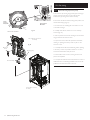
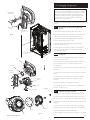
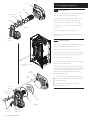
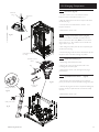
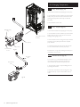
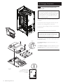
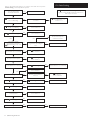
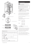
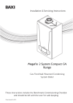
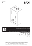
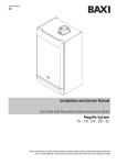
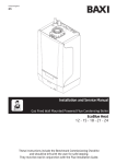
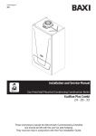
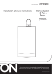
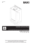
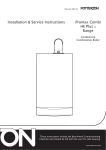
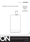
10.0 Commissioning
10.2
Flue Sampling
Point
Checking the Combustion - ‘Chimney Sweep’
Function
1. To set the boiler to operate at MAXIMUM and MINIMUM,
press
&
together and hold for at least 6
seconds. ‘On’ will be displayed briefly, followed by ‘304’ then
the boiler output expressed as percentage i.e. ‘100’.
Plug
Analyser Probe
Fig. 36a
2. Press
input.
until ‘00’ is displayed, indicating minimum
3. To exit the function press
seconds.
&
together for 6
4. The combustion (CO level and CO/CO2 ration) must be
measured and recorded at MAXIMUM DHW input and
MINIMUM input.
5. Follow the flow chart on the next page to comply with the
requirement to check combustion on commissioning.
6. The system MUST be cold to ensure the boiler is operating
under full demand
© Baxi Heating UK Ltd 2014
27
Set Boiler to Maximum Rate
(see 10.2.1)
Allow the combustion to
stabilise. Do not insert probe to
avoid ‘flooding’ the analyser.
Verify Flue Integrity
Indication that products of
combustion & inlet air are
mixing - further investigation is
required.
Check all flue components are
correctly assembled, fixed &
supported. Check the flue &
terminal are unobstructed.
Is O2 ≥ 20.6% and
CO2 < 0.2% ?
No
TURN APPLIANCE OFF !
Call 0844 871 1555 for
advice.
The appliance MUST NOT be
commissioned until all
problems are identified and
resolved.
10.0 Commissioning
10.2
1. This procedure is mandatory in GB from April 2014. It is
strongly recommended to perform the procedure before that
date.
Perform Flue Integrity
Combustion Check
Insert the analyser probe into the
air inlet test point, allowing the
reading to stabilise.
No
Is O2 ≥ 20.6% and
CO2 < 0.2% ?
Check CO & Combustion Ratio
at Maximum Rate
Whilst the boiler is still
operating at maximum insert the
analyser probe into the flue gas
test point, allowing the reading to
stabilise.
Yes
Yes
Checking the Combustion - ‘Chimney Sweep’
Function (cont)
No
Is CO < 350ppm
and CO/CO2 ratio
< 0.004 ?
Verify Integrity of Seals
Check all burner seals, internal
flue seals, door & case seals.
Replace any seals that appear
unsound.
Is CO < 350ppm and
CO/CO2 ratio <
0.004 ?
Yes
Set Boiler to Minimum Rate
(see 10.2.2)
Allow the combustion to
stabilise. Do not insert probe to
avoid ‘flooding’ the analyser.
Check CO & Combustion Ratio
at Minimum Rate
Whilst the boiler is
operating at minimum insert the
analyser probe into the flue gas
test point, allowing the reading to
stabilise.
Yes
No
TURN APPLIANCE OFF !
Call 0844 871 1555 for advice.
The appliance MUST NOT be
commissioned until all
problems are identified and
resolved.
If commissioning cannot be fully
completed the appliance must be
disconnected from the gas supply
in accordance with the GSIUR.
Note: Check & record the CO &
combustion ratio at both
maximum & minimum rates before
calling 0844 871 1555.
28
© Baxi Heating UK Ltd 2014
No
Is CO < 350ppm and
CO/CO2 ratio <
0.004 ?
Yes
BOILER OPERATING
SATISFACTORILY. NO
FURTHER ACTION
REQUIRED
Ensure test points are capped, the
boiler case front panel is correctly
fitted & secured and all other
commissioning procedures
completed.
Complete the ‘Benchmark’
Checklist, recording the CO &
combustion ratio readings as
required.
10.0 Commissioning
10.3
Check the Operational (Working) Gas Inlet
Pressure & Gas Rate
Note: The system MUST be cold to ensure the boiler is
operating under full demand.
1. Press
&
together and hold for at least 6
seconds. ‘On’ will be displayed briefly, followed by ‘304’
then ‘100’ when the boiler is lit, indicating the output is at
MAXIMUM (‘Chimney Sweep Function’).
2. With the boiler operating in the maximum rate condition
check that the operational (working) gas pressure at the inlet
gas pressure test point on the gas cock or valve is in
accordance with B.S. 6798 & B.S. 6891. This must be AT
LEAST 17mb ! (LPG - 37mb)
Measure the Gas Rate
4. With any other appliances & pilot lights turned OFF the gas
rate can be measured. It should be:-
DO NOT check gas pressure here
Fig. 37
Inlet Gas Pressure Test Point
Fig. 38
Gas Type Label
Natural Gas
12 model
15 model
18 model
24 model
28 model
32 model
1.27 m3/h
1.59 m3/h
1.90 m3/h
2.54 m3/h
2.96 m3/h
3.40 m3/h
Propane
12 model
15 model
18 model
24 model
28 model
32 model
0.93 kg/h
1.17 kg/h
1.4 kg/h
1.86 kg/h
2.18 kg/h
2.49 kg/h
5. Press
&
together and hold for at least 6
seconds to exit the function.
N.G. Factory
Set
6. Carefully read and complete all sections of the Benchmark
Commissioning Checklist at the rear of this publication that are
relevant to the boiler and installation. These details will be
required in the event of any warranty work. The publication
must be handed to the user for safe keeping and each
subsequent regular service visit recorded.
When reset for
L.P.G.
Changing the Gas Type
1. It may be necessary to adjust the boiler gas type if the supply is changed, for example
when Natural Gas is provided to a rural area previously reliant on Propane. In these
instances a replacement Gas Type Label may be required, which is available on request
as a spare part..
2. Press
&
alternating with
.
3. Press
to select the next parameter
4. Press
or
gas type. For Natural Gas:For Propane:5. Press
and hold for at least 6 seconds.
will be displayed,
.
to select the value that corresponds with the required
to save the change, then
© Baxi Heating UK Ltd 2014
. Press
7. For IE, it is necessary to complete a “Declaration of
Conformity” to indicate compliance with I.S. 813. An example
of this is given in I.S. 813 “Domestic Gas Installations”. This is
in addition to the Benchmark Commissioning Checklist.
R to return to the normal display.
29
11.0 Completion & System Draining
11.1
Completion
1. Replace the case front panel, and secure with the screws
previously removed.
2. This publication must be handed to the user for safe
keeping and each subsequent regular service visit recorded.
Case Front Panel
3. Set the central heating and hot water temperatures to
the requirements of the user. Instruct the user in the
operation of the boiler and system.
4. Instruct the user in the operation of the boiler controls.
Hand over the User’s Operating, Installation and Servicing
Instructions, giving advice on the necessity of regular
servicing.
5. Demonstrate to the user the action required if a gas leak
occurs or is suspected. Show them how to turn off the gas
supply at the meter control, and advise them not to operate
electric light or power switches, and to ventilate the
property.
Facia Panel
Fig. 39
To change the information
displayed see the table below:The
button can be pressed so that the display shows the following
information:1 press - ‘00’ alternates with Sub-Code (only when fault on boiler) or ‘000’
2 presses - ‘01’ alternates with CH Flow Temperature
3 presses - ‘02’ alternates with Outside Temperature (where Sensor fitted)
4 presses - ‘03’ alternates with DHW Temperature
5 presses - ‘04’ alternates with DHW Temperature
6 presses - ‘05’ alternates with System Water Pressure
7 presses - ‘06’ alternates with CH Return Temperature
8 presses - ‘07’ alternates with Flue Temperature
9 presses - ‘08’ alternates with Heat Exchanger Temperature
6. Show the user the location of the system control isolation
switch, and demonstrate its operation.
7. Advise the user that they may observe a plume of vapour
from the flue terminal, and that it is part of the normal
operation of the boiler.
11.2
System Draining
1. If at any time after installation it is necessary to drain the
central heating system (e.g. after replacing a radiator) the
De-Aeration Function should be activated.
2. On refilling the system ensure that there is no heating or
hot water demand, but that there is power to the boiler.
3. Press
&
together and hold for at least 6
seconds. The ‘De-Aeration’ Function will be activated.
4. The boiler pump will run for up to 10 minutes. This will
purge air from the system. The display will show
.
5. Once De-Aeration is complete set the external controls
as required by the user.
30
© Baxi Heating UK Ltd 2014
12.0 Servicing
Flue Sampling
Point
12.1
Annual Servicing
1. For reasons of safety and economy, it is recommended that
the boiler is serviced annually. Servicing must be performed by
a competent person in accordance with B.S. 7967-4.
Air Sampling
Point
2. After servicing, complete the relevant Service Interval Record
section of the Benchmark Commissioning Checklist at the rear
of this publication.
IMPORTANT: During routine servicing, and after any
maintenance or change of part of the combustion circuit, the
following must be checked:• The integrity of the complete flue system and the flue seals
(check air inlet sample).
• The integrity of the boiler combustion circuit and relevant
seals as described in Section 12.2.
• The operational gas inlet pressure as described in Section
10.2.1 to 10.2.7 and the gas rate as described in 10.2.8.
• The combustion performance as described in ‘Check the
Combustion Performance’ (12.1.4 to 12.1.6 below).
3. Competence to carry out Checking Combustion
Performance
B.S. 6798 ‘Specification for Installation & Maintenance of Gas
Fired Boilers not exceeding 70kW’ advises that:-
Case Front Panel
Fig. 40
• The person carrying out a combustion measurement should
have been assessed as competent in the use of a flue gas
analyser and the interpretation of the results.
Case Front Panel
Securing Screws
• The flue gas analyser used should be one meeting the
requirements of BS7927 or BS-EN50379-3 and be calibrated
in accordance with the analyser manufacturers’ requirements.
• Competence can be demonstrated by satisfactory
completion of the CPA1 ACS assessment, which covers the
use of electronic portable combustion gas analysers in
accordance with BS 7967, Parts 1 to 4.
Check the Combustion Performance (CO/CO2 ratio)
4. Set the boiler to operate at maximum rate as described in
Section 14.1.1 to 14.1.6.
5. Remove the plug from the flue sampling point, insert the
analyser probe and obtain the CO/CO2 ratio. This must be
less than 0.004.
6. If the combustion reading (CO/CO2 ratio) is greater than
this, and the integrity of the complete flue system and
combustion circuit seals has been verified, and the inlet gas
pressure and gas rate are satisfactory either:
• Perform the ‘Annual Servicing - Inspection’ (Section 12.2) &
re-check
• Adjust the gas valve (Section 14.0) & re-check
• Replace the gas valve (Section 13.23) & re-check
Control Box removed
for clarity
Condensate Trap
12.2
Gasket
Annual Servicing - Inspection
1. Ensure that the boiler is cool.
Sump
2. Ensure that both the gas and electrical supplies to the
boiler are isolated.
3. Remove the screws securing the case front panel. Lift the
panel slightly to disengage it from the studs on top of the case
(Fig. 40) and hinge down the Control Box.
Fig. 41
© Baxi Heating UK Ltd 2014
4. Disconnect the condensate drain pipe and unscrew the sump
from the bottom of the condensate trap assembly (Fig. 41).
Remove any deposits from the sump and trap. Clean as
necessary and replace the sump.
31
4 ±0.5
12.0 Servicing
12.2
Annual Servicing Inspection (Cont)
5. Remove the clip securing the gas feed pipe to the air/gas
venturi. Disconnect the pipe. Do not break the joint
between the pipe and gas valve unless necessary.
6. Disconnect the electrode leads, noting their position, and
the fan electrical plugs (Fig. 43).
Flame
Sensing
Electrode
5±
1
Spark Ignition
Electrode
10 ±1
Fig. 42
Electrode Position
Fan, Collector and Cover
Assembly
Fig. 43
Electrode
Leads
Securing Clip
7. Undo the four nuts retaining the combustion box cover
to the heat exchanger.
8. Carefully draw the fan, collector and cover assembly
forward (Figs. 43).
9. Clean any debris from the heat exchanger and check that
the gaps between the tubes are clear.
10. Inspect the burner, electrodes position and insulation,
cleaning or replacing if necessary. Clean any dirt or dust
from the air box.
11. Carefully examine all seals, insulation & gaskets, replacing
as necessary. Look for any evidence of leaks or corrosion,
and if found determine & rectify the cause.
12. Reassemble in reverse order, ensuring the front case
panel is securely fitted.
13. Complete the relevant Service Interval Record section of
the Benchmark Commissioning Checklist at the rear of this
publication and then hand it back to the user.
Gas Feed Pipe
Control Box removed
for clarity
32
© Baxi Heating UK Ltd 2014
13.0 Changing Components
IMPORTANT: When changing components ensure that
both the gas and electrical supplies to the boiler are isolated
before any work is started. When the component has been
changed recommission the boiler as described in Section
10.0. Always examine any seals or gaskets, replacing where
necessary. The Case Front Panel MUST seal effectively
against the air box side panels.
Spark Ignition
Electrode
See Section 12.1 “Annual Servicing” for removal of case panel,
door etc.
Electrode
Leads
13.1
Flame Sensing
Electrode
Spark Ignition and Flame Sensing Electrodes
(Fig. 44)
1. Disconnect the electrode leads, noting their positions.
2. Remove the retaining screws securing each of the electrodes
to the combustion box cover and remove the electrodes.
Fig. 44
3. Check the condition of the sealing gaskets and replace if
necessary. Reassemble in reverse order.
4. After changing the Flame Sensing Electrode check the
combustion - see Section 14.1.
5. When satisfactory combustion readings are not obtained
ensure the electrode position is correct and perform the
combustion check again.
Control Box removed
for clarity
13.2
Fan (Fig. 45)
1. Remove the clip securing the gas feed pipe to the air/gas
venturi. Disconnect the pipe.
Cover
2. Undo the screws securing the air/gas collector to the cover
(32) or extension piece (12 - 28) and disconnect the fan
electrical plugs.
Gasket
3. Remove the collector and fan assembly, being careful to retain
the gasket.
Air/Gas
Collector
4. Undo the screws securing the fan to the collector. Retain the
gasket.
5. Undo the screws securing the venturi to the fan (noting its
position) and transfer to the new fan, replacing the seal if
necessary.
Air/Gas
Venturi
6. Examine the gasket(s) and replace if necessary.
Fan
Fig. 45
Gas Feed Pipe
7. Reassemble in reverse order and perform the Calibration
Function - see Section 14.2.
13.3
Air/Gas Venturi (Figs. 45 & 46)
1. Remove the clip securing the gas feed pipe to the venturi.
2. Undo the screws securing the collector to the cover (32) or
extension piece (12 - 28) and disconnect the fan electrical plugs.
3. Remove the collector and fan assembly, being careful to retain
the gasket.
4. Undo the screws securing the venturi to the fan (noting its
position) and fit the new venturi, replacing the seal if necessary.
Venturi
Gasket
Fan
© Baxi Heating UK Ltd 2014
Fig. 46
5. Examine the gasket and replace if necessary.
6. After changing the venturi check the combustion - see Section
14.1.
33
Cover
13.0 Changing Components
Burner
13.4
Gasket
Burner (Fig. 47)
1. Remove the clip securing the gas feed pipe to the air/gas
venturi and disconnect the fan electrical plugs.
Extension Piece
(12 - 28 models)
2. Undo the screws securing the air/gas collector to the
cover (32) or extension piece (12 - 28). Remove this
extension piece from the cover (on 12 - 28 models).
Gasket
3. Withdraw the burner from the cover and replace with
the new one.
Fig. 47
4. Examine the gasket(s), replacing if necessary.
5. After changing the burner check the combustion - see
Section 14.1.
Air/Gas
Collector
13.5
Insulation (Fig. 48)
1. Remove the clip securing the gas feed pipe to the air/gas
venturi and disconnect the fan electrical plugs.
2. Remove the electrodes as described in section 13.1.
3. Undo the nuts holding the cover to the heat exchanger.
Draw the air/gas collector, fan and cover assembly away.
4. Remove the cover insulation piece.
5. Fit the new insulation carefully over the burner and align
it with the slots for the electrodes.
Control Box removed
for clarity
6. If the rear insulation requires replacement, remove it and
all debris from the heat exchanger. Also it may be necessary
to separately remove the spring clip from the pin in the
centre of the heat exchanger and the ‘L’ shaped clips
embedded in the insulation.
Heat
Exchanger
Rear
Insulation
7. Do not remove the shrink-wrapped coating from the
replacement rear insulation. Keep the insulation vertical and
press firmly into position.
8. Examine the cover seal and replace if necessary.
Reassemble in reverse order.
Air/Gas
Collector
Spark Ignition
Electrode
Cover
Insulation
Seal
Fig. 48
Electrode
Leads
34
Flame Sensing
Electrode
© Baxi Heating UK Ltd 2014
13.0 Changing Components
Electrical
Plug
13.6
Flue Sensor (Fig. 49)
1. For ease of access on 12 - 28 models remove the
Expansion Vessel as described in Section 13.17.
Flue Sensor
2. Ease the retaining tab on the sensor away and disconnect
the electrical plug.
3. Turn the sensor 90° anticlockwise to remove - it is a
bayonet connection.
4. Reassemble in reverse order.
Fig. 49
13.7
Heating Flow & Return Sensors (Fig. 50)
1. There is one sensor on the flow (red wires) and one
sensor on the return (blue wires). Note: For access to the
return sensor on 12 - 28 models first remove the fan and
air/gas collector (see 13.2).
2. After noting the position prise the sensor clip off the pipe
and disconnect the plug.
3. Connect the plug to the new sensor and ease the clip onto
the pipe as close to the heat exchanger as possible.
Control Box removed
for clarity
13.8
Hydraulic Pressure
Sensor
Safety Thermostat (Fig. 51)
1. Pull the plug off the safety thermostat.
2. Remove the screws securing the thermostat to the
mounting plate on the flow pipe.
Plug
3. Reassemble in reverse order, ensuring that the plug is
pushed fully on.
13.9
Fig. 52
Heating Flow Sensor
Fig. 50
Securing Clip
(captive)
Hydraulic Pressure Sensor
(Fig. 52)
1. Close the flow and return isolation taps and drain the
primary circuit. Remove the fan and heat exchanger flow pipe.
2. Remove the plug from the sensor and pull the retaining clip
forwards. The clip is captive and does not need to be fully
removed.
3. Reassemble in reverse order.
Safety Thermostat
Fig. 51
© Baxi Heating UK Ltd 2014
35
13.0 Changing Components
13.10
Pump - Head Only (Fig. 53)
1. Disconnect the electrical supply plug from the pump.
2. Close the flow and return isolation taps and drain the
boiler primary circuit. Remove the socket head screws
securing the pump head to the body and draw the
head away.
3. Reassemble in reverse order.
13.11
Electrical Supply
Plug
1. Disconnect the electrical supply plug from the pump.
Control Box removed
for clarity
Pump Body
2. Close the flow and return isolation taps and drain the
boiler primary circuit. For ease of access remove the
heating pressure gauge (13.14).
3. Undo the three screws securing the body to the inlet
assembly and pump flow pipe. Draw the complete
pump forwards.
4. Pull off the securing clip and remove the automatic
air vent. Transfer them to the new pump body.
Pump Head
Socket Headed
Screw
Pump - Complete (Fig. 54)
Fig. 53
5. Examine the ‘O’ ring seals, replacing if necessary and
reassemble in reverse order.
Pump Flow
Pipe
13.12
Automatic Air Vent (Fig. 54)
1. For access on 12 - 28 models see Section 13.17 to
remove the expansion vessel. Close the flow and
return isolation taps and drain the primary circuit.
Automatic Air
Vent
2. The automatic air vent is a bayonet fitting. Remove
by twisting anticlockwise.
3. Fit the new automatic air vent, ensuring the ‘O’ ring
is fitted and the cap is open . Reassemble in reverse
order.
Fig. 54
36
© Baxi Heating UK Ltd 2014
13.0 Changing Components
Clip
13.13
Safety Pressure Relief Valve (Fig. 55)
1. Close the flow and return isolation taps and drain the
primary circuit.
‘O’ Ring Seal
2. For access remove the screws securing the
condensate trap, and pull off the pipe from the heat
exchanger. Ease the trap to one side.
Pressure Relief
Valve
3. Disconnect the discharge pipe from the pressure relief
valve and remove the sealing grommet.
Discharge Pipe
4. Pull off the clip retaining the valve and withdraw it
from the outlet assembly.
Fig. 55
5. Fit the new valve and ‘O’ ring seal and reconnect the
discharge pipe. Ensure the grommet is correctly refitted
to maintain the integrity of the case seal. Refit the
condensate trap.
13.14
Heating Pressure Gauge (Figs. 56 & 57)
1. Close the flow and return isolation taps and drain the
primary circuit.
2. Remove the gauge from the boiler lower panel.
3. Remove the clip securing the pressure gauge capillary.
4. Fit the new gauge, ensuring that the capillary is routed
to prevent any sharp bends. Reassemble in reverse order
and ensure the gauge is firmly in position to maintain the
integrity of the case seal.
Control Box removed
for clarity
Heating
Pressure
Gauge
Heating Pressure
Gauge Capillary
Clip
Fig. 56
Fig. 57
© Baxi Heating UK Ltd 2014
37
13.0 Changing Components
13.15
P.C.B. & R.D.S. (Removable Data Stick)
(Fig. 58)
NOTE: Both P.C.B. and R.D.S. are available as spare
parts. The P.C.B. is suitable for any boiler model. An
R.D.S. specific to the boiler model output & gas type will
be required if the R.D.S. from the original P.C.B. is not
being transferred. It is recommended that P.C.B. and
R.D.S. are replaced together.
1. Ensure that the power to the boiler is isolated and wait
10 seconds.
2. Remove the screws securing the control box cover and
release the cover retaining barbs from their slots.
3. Note the position of all plugs and wires on the P.C.B. and
disconnect them.
4. Undo the securing screws and remove the P.C.B.
IMPORTANT: If only the P.C.B. is being replaced
transfer the R.D.S. from the original board to the new
one. Where both P.C.B. and R.D.S. are being replaced
ensure the new R.D.S. is on new the board.
5. Reassemble in reverse order. Ensure that the ignition lead
is connected correctly.
R.D.S.
6. P.C.B. ONLY changed - Check the Combustion - see
Section 14.1.
7. P.C.B. & R.D.S. changed - enable the Calibration Function
as described in Section 14.2, then Check the Combustion see Section 14.1.
Fig. 58
Note the correct
orientation of the R.D.S.
Position with the chamfer
as shown.
X24
X20
X22
X1
X36
X2
X37
X23
X3
38
© Baxi Heating UK Ltd 2014
X10
X13
X11
X12
13.0 Changing Components
Gas Feed
Pipe
NOTE: The Injector Washer MUST
be fitted as shown between the
Valve & Pipe. DO NOT fit the
Injector Washer between the Gas
Cock & Valve
Injector
Washer
13.16
Gas Valve (Fig. 59)
IMPORTANT: After replacing the valve the CO2 must be
checked and adjusted as detailed in Section 14.0
Combustion & Calibration. Only change the valve if a
suitable calibrated combustion analyser is available,
operated by a competent - see section 12.1.
1. Turn the gas cock off and undo the nut under the boiler.
Retain the washer.
Gas Valve
2. Remove the electrical plug from the valve.
Electrical Plug
3. Undo the nut on the gas feed pipe and ease the pipe aside.
It is recommended that the injector washer is changed as well.
4. Remove the screws securing the gas valve to the boiler
bottom panel.
Washer
Gas Cock
5. Reassemble in reverse order, ensuring the injector washer is
in place, and perform the Calibration Function & Combustion
Check - see Sections 14.1 & 14.2.
NOTE: Check for gas tightness after replacing gas valve.
Fig. 59
13.17
Expansion Vessel (Fig. 60)
1. Close the flow and return isolation taps and drain the
primary circuit.
2. Prise off the securing clip and disconnect the braided hose
from the vessel.
Lock Nut
3. Whilst supporting the vessel undo the locknut and
manoeuvre the vessel out of the boiler.
4. Reassemble in reverse order.
Expansion
Vessel
Fig. 60
© Baxi Heating UK Ltd 2014
39
14.0 Combustion & Calibration
IMPORTANT: DO NOT insert the Analyser
Probe into the Test Point immediately. This will
prevent saturation of the analyser.
During the Calibration Function the combustion
ratio may increase for a short time while the
boiler performance is optimised.
14.1
Checking the Combustion
1. Combustion should be:Natural Gas 9.0% CO2 ± 0.7
Propane 10.5% CO2 ± 1.0
at all 3 fan speeds:- ‘100’ (Maximum), the Ignition Phase speed
and ‘00’(Minimum).
2. Press
&
together and hold for at least 6
seconds. ‘On’ will be displayed briefly, followed by ‘304’ then
the boiler CH output expressed as percentage i.e. ‘100’.
The person carrying out a combustion
measurement should have been assessed as
competent in the use of a flue gas analyser and
the interpretation of the results.
The flue gas analyser used should be one meeting
the requirements of BS7927 or BS-EN50379-3
and be calibrated in accordance with the analyser
manufacturers’ requirements.
3. Insert the analyser probe and once stabilised note the CO2
reading.
4. Press
to select the Ignition Phase Speed. A value will
be displayed, e.g. ‘33’. Note the CO2 reading.
5. Press
again to select the Minimum Output. ‘00’ will
be displayed. Note the CO2 reading.
6. If the CO2 is not within the tolerances referred to above at
any of the speeds, follow the procedure in Section 14.3
opposite to calibrate the boiler.
Flue Sampling
Point
7. To exit the function press
seconds.
Plug
Analyser Probe
14.2
&
together for 6
Calibration Function
Fig. 61
IMPORTANT: Do not commence the Calibration Function
whilst the burner is lit ! The Case Front Panel MUST be fitted.
14.3
Adjusting the CO2
1. Press
&
together and hold for at least 6
seconds. ‘On’ will be displayed briefly, followed by ‘304’ then
the boiler CH output expressed as percentage i.e. ‘100’.
2. Press
to select the adjustment function. ‘0’ will alternate
&
buttons adjust ‘0’
with ‘304’. Using the
between ‘-3’ & ‘3’.
3. Decreasing the value lowers the CO2, and selecting a higher
value will increase CO2.
4. Once the correct CO2 reading is achieved press
return to the fan speed selection.
to
5. Using
or
to select the next fan speed. ‘00’
indicates MINIMUM speed, the other speed (Ignition Phase) will
be indicated by, for example ‘33’ (this varies depending on
boiler model).
6. Repeat step 2. above to adjust the CO2.at Ignition Phase and
Minimum fan speeds. Press
&
together and hold
for at least 6 seconds to exit the function.
Note: To obtain an accurate measurement on smaller
capacity systems it may be necessary to open one or more
hot taps in order to maintain the boiler at full rate.
1. The function is activated by pressing buttons
and
R together for 6 seconds then quickly pressing button
while ‘On’ is displayed. The Ignition Phase fan speed code will
then be displayed. Calibration will take approximately 5 minutes.
2. If ‘304’ is displayed, then the Calibration Function has not
been activated correctly. Isolate and reinstate all power sources
to the boiler and repeat the above.
3. The boiler will automatically calibrate at ‘100’, the Ignition
Phase speed then ‘00’. These represent the percentage of
MAXIMUM fan speed (i.e. ‘00’ is MINIMUM fan speed). Once
the boiler has stabilised and self-calibrated at each fan speed the
and
symbols will be displayed before the next speed is
automatically set.
4. When self-calibration is complete the boiler will run at
MINIMUM fan speed (‘00’displayed). The following symbols will
also be displayed
flashing together at regular
intervals.
5. To exit the function press
R . ‘ESC’ will be displayed and
the calibration function completed.
40
© Baxi Heating UK Ltd 2014
15.0 Electrical
15.1
Illustrated Wiring Diagram
Gas
Valve
Fan
Flue Sensor
Hydraulic
Pressure
Switch
Safety
Thermostat
Heating
Return
Sensor
b b
Terminal
Strip
Heating
Flow
Sensor
bk
r
b
b
g
br bk
b
X23
X3
bk
b
b
X37
w
g br
g
b
X36
r
b r
X22
br
X20
br
X24
w
br
X10
g/y
b
b
b
br
X13
bk
bk
b
br
M2
Low Voltage
External Control
Connection
X11
bk
g/y
gr
X12
X1
X2
g/y
g/y
g/y
Pump
Spark
Ignition
Electrode
g/y
Flame
Sensing
Electrode
Key To Wiring Colours
b - Blue
r - Red
bk - Black
g - Green
br - Brown
g/y - Green/Yellow
w - White
y - Yellow
gr - Grey
© Baxi Heating UK Ltd 2014
41
16.0 Short Parts List
Short Parts List
B
Key
No.
Description
No.
A
Fan
720768101
Burner (12/15/18/24/28)
720767901
B
Manufacturers
Part No.
Burner (32)
A
C
Spark Ignition Electrode
720767301
D
Flame Sensing Electrode
720767101
E
Gas Valve
720752301
F
Safety Thermostat
720765301
G
Pump
720777401
H
Heating Flow/ Return Sensor
720747101
J
Pump Air Vent
720777601
K
Hydraulic Pressure Sensor
720778001
L
Heating Pressure Gauge
720776601
R
Flue Sensor
720851401
N
PCB only
720878102
O
R.D.S. - 12
720845601
R.D.S. - 15
720845901
R.D.S. - 18
720846201
R.D.S. - 24
720846501
R.D.S. - 28
720846801
D
C
E
F
H
G
J
L
K
P
M
O
R.D.S. - 32
720847101
R.D.S. - 12 LPG
720847401
R.D.S. - 15 LPG
720847701
R.D.S. - 18 LPG
720848001
R.D.S. - 24 LPG
720848301
R.D.S. - 28 LPG
720848601
R.D.S. - 32 LPG
720848901
Air/Gas Venturi 12
720820701
Air/Gas Venturi 15
720750301
Air/Gas Venturi 18
720750501
Air/Gas Venturi 24
720750701
Air/Gas Venturi 28
720785401
Air/Gas Venturi 32
720785601
Injector Washer - 12 (Ø 3.0)
720821101
Injector Washer - 15 (Ø 3.3)
720821301
Injector Washer - 18 (Ø 3.6)
720821501
Injector Washer - 24 (Ø 4.6)
720775801
Injector Washer - 28 (Ø 4.9)
720776001
Injector Washer - 32 (Ø 5.8)
720786601
N
Q
Q
P
42
© Baxi Heating UK Ltd 2014
Table Of Error Codes
09
Gas Valve Connection Cable
15
Gas Valve Fault
20
Central Heating NTC Fault
28
Flue NTC Fault
40
Central Heating Return NTC Fault
55
Calibration Required
109
Pre-circulation Fault
110
Safety Thermostat Operated
117
Primary System Water Pressure Too High
118
Primary System Water Pressure Too Low
125
Circulation Fault (Primary)
128
Flame Failure
130
Flue NTC Operated
133
Interruption Of Gas Supply or Flame Failure
134
Elapsed Time - Gas Valve Open Without Gas
135
Interruption Of Gas Supply (Internal Error)
154
Flow/Return Sensor Temperature Test
160
Fan or Fan Wiring Fault
270
Circulation Fault (Dry Fire)
384
False Flame
17.0 Fault Finding
17.1
1. Check that gas, water and electrical supplies are available
at the boiler.
2. Electrical supply = 230V ~ 50 Hz.
3. The preferred minimum gas pressure is 20mb (NG) 37mb
(LPG).
4. Carry out electrical system checks, i.e. Earth Continuity,
Resistance to Earth, Short Circuit and Polarity with a suitable
meter.
NOTE: These checks must be repeated after any
servicing or fault finding.
5. Ensure all external controls are calling for heat and check
all external and internal fuses. Before any servicing or
replacement of parts, ensure the gas and electrical supplies
are isolated.
The
button can be pressed so that the display shows the following
information:1 press - ‘00’ alternates with Sub-Code (only when fault on boiler) or ‘000’
2 presses - ‘01’ alternates with CH Temperature
3 presses - ‘02’ alternates with Outside Temperature (where Sensor fitted)
4 presses - ‘03’ alternates with DHW Temperature
5 presses - ‘04’ alternates with DHW Temperature
6 presses - ‘05’ alternates with System Water Pressure
7 presses - ‘06’ alternates with Return Temperature
8 presses - ‘04’ alternates with Flue Temperature
9 presses - ‘05’ alternates with Heat Exchanger Temperature
1. After 11 months operation the ‘Service Due’ message will
be shown on the boiler display. (If the installation has been
subject to prolonged electrical isolation or power cuts this
period may be longer than 11 months)
2. Once the service has been completed satisfactorily the
‘Service Due’ message can be reset or de-activated.
4. Press
to scroll to ‘15’. Confirm with
press
R to return the display to normal.
To De-activate
5. Press
&
for 6 seconds. Using
.
through until ‘22’ is displayed. Press
8. Press
Using
until ‘22’ is displayed again. Press
.
scroll through to ‘50’. Press
9. Press
then press
R to return the display to normal.
© Baxi Heating UK Ltd 2014
until ‘25’ is displayed. Confirm with
17.2
Error Codes
1. If a fault occurs on the boiler an error code may be shown
by the facia display.
2. The codes are a flashing number, either two or three digit,
preceded by the symbol :followed by 20, 28, 40, or 160 indicates possible faulty
components.
followed by 55 (after replacing R.D.S.) indicates calibration
required (Section 14.2).
110 indicates overheat of the primary system water.
‘Service Due’ Message
To Reset
3. Press
&
for 6 seconds. Using
.
through until ‘22’ is displayed. Press
Initial Fault Finding Checks
117 is displayed when the primary water pressure is greater
than 2.7 bar.
118 is displayed when the primary water pressure is less than
0.5 bar.
133, 134 and 135 indicate that the gas supply has been
interrupted, ignition has failed or the flame has not been
detected.
scroll
128 is displayed if there has been a flame failure during
normal operation.
then
scroll
.
125 is displayed in either of two situations:i) If between 15 and 30 seconds of the burner lighting the boiler
temperature has not changed by 1°C.
ii) If within 10 minutes of the burner lighting the boiler actual
temperature twice exceeds the selected temperature by 30°.
In these instances poor primary circulation is indicated.
3. By pressing the 'Reset' button for 1 to 3 seconds when
110, 125, 133, 134, 135, 09, 15, 128 & 384 are displayed
it is possible to relight the boiler.
4. If this does not have any effect, or the codes are displayed
regularly further investigation is required.
43
17.0 Fault Finding
Refer to “Illustrated Wiring Diagram” for position of terminals and components
Central Heating - Follow operational sequence
Turn on mains power
The display illuminates
NO
If
09, 15, 110 or 384 is flashing or re-occurs
regularly, check all PCB connections. If this has no
effect replace the PCB.
Go to section ‘A’
YES
09, 15, 110, 125, 133, 134,
135 or 384 flashing
YES
If
Press the reset button for 1 to
3 seconds
110 is still flashing go to
section ‘H’
NO
20, 28, or 40 flashing
YES
Go to section ‘D’
NO
117 or 118 flashing
YES
Go to section ‘I’
Ensure controls are set to
demand and verify the
contacts are closed
NO
NO
Set Central Heating
temperature to Maximum.
symbol flashing, pump runs
NO
Ensure all controls and
programmers are calling for
heat
YES
Go to section ‘B’
YES
Fan runs after up to 3 minutes
NO
160 flashing
Go to section ‘C’
NO
160 flashing
Go to section ‘C’
YES
Fan runs at correct speed
NO
Spark at ignition electrodes up
to 5 seconds & for 3 attempts
NO
YES
133 flashing
YES
Go to section ‘F’. Press the
reset button for 1 to 3 seconds
YES
133 flashing
Go to section ‘G’
Go to section ‘E’
NO
Burner lights
YES
Burner goes out after 5
seconds
YES
109 flashing
YES
Go to section ‘J’
125 flashing after 1 min
NO
110 flashing
YES
Go to section ‘H’
NO
Burner modulates to maintain
set temperature
NO
Check Heating flow sensor.
Go to section ‘D’
NO
130 flashing
YES
Go to section ‘K’
NO
Burner goes out
44
© Baxi Heating UK Ltd 2014
YES
Fan stops after 10 seconds
YES
Boiler operation correct
17.0 Fault Finding
Fault Finding Solutions Sections
A
Is there 230V at:
1.
2.
3.
B
Main terminals L and N
NO
Check electrical supply
NO
Main terminal fuse
PCB - X10 connector
Main terminals L and N
Connection
OK at X41
Replace fuse
NO
Check wiring
YES
230V at PCB - X13 connector (between
blue & brown - see Wiring Diagram)
230V at pump
YES
Display
illuminated
NO
Display or
Main PCB fault
Replace pump
NO
NO
Check wiring
Replace PCB
C
Fan connections correct at fan & PCB
X11 and X23 connectors - see
Wiring Diagram.
NO
Make connections
YES
YES
230V at PCB - X11 connector (between
blue & brown - see Wiring Diagram)
Fan jammed or
faulty wiring
YES
Replace fan or wire
NO
Replace PCB
D
Temperature sensor faulty.
Check correct location and wiring.
YES
Cold resistance approximately
10kΩ @ 25° C (Flow & Return sensors)
(resistance reduces with increase in temp.)
E
Gas at burner
NO
NO
Replace sensor
Ensure gas is on and purged
Check wiring and PCB - X36 connector
see Wiring Diagram
YES
Replace gas valve
NO
Replace PCB
© Baxi Heating UK Ltd 2014
45
17.0 Fault Finding
F
Check and correct if necessary
1. Ignition electrode and lead
2. Electrode connection
3. Spark gap and position
YES
NO
Check wiring - see Diagram
Replace PCB
Viewing Window
2.
4 ±0.5
1.
Check supply pressure at the
gas valve:Natural Gas - Minimum 17 mbar
Propane - Minimum 37 mbar
Check and correct if necessary
1. The set of the gas valve
(CO2 values - see instruction)
2. Flame sensing electrode and lead connections
3. Flame sensing electrode position
Flame
Sensing
Electrode
Spark Ignition
Electrode
5±
1
G
Burner
10 ±1
Electrode Position
Replace flame sensing electrode or PCB
H
Safety thermostat operated or
faulty
NO
Check for and correct any
system faults
NO
Allow to cool. Continuity
across thermostat terminals
more than 1.5 ohm
YES
Replace safety thermostat
NO
Check Flow & Return Sensors see section ‘D’
YES
Is
110 still flashing ?
YES
I
CH system pressure less than
0.5 bar or greater than 2.7 bar
NO
J
Restore system pressure
YES
Check wiring and PCB - X22
connector for approx. 5V DC
between green & black - see
Wiring Diagram
Ensure that the boiler and system
are fully vented
YES
YES
NO
1.
2.
46
Replace PCB
System fault - correct
Check flow temperature sensor connections
and position.
Cold resistance approximately
10kΩ @ 25° C (CH sensors)
(resistance reduces with increase in temp.)
Temperature sensors faulty.
Cold resistance approximately
10kΩ @ 25° C (CH sensor)
20kΩ @ 25° C (Flue sensor)
(resistance reduces with increase in temp.)
If pump is running the heat exchanger could be
obstructed
© Baxi Heating UK Ltd 2014
Replace hydraulic pressure sensor
NO
YES
K
Replace PCB
NO
Go to section ‘B’
NO
YES
Replace sensor
Replace heat exchanger
Replace sensor
18.0 32 kW Model Supplement
Appliance Type
C13 C33 C43 C53
Appliance Category
CAT II 2H 3P
Heat Input CH (Net)
32 model
kW
Max
32
Min
4.6
Heat Output CH (Condensing)
Max
32 model
kW
33.8
Min
5
mm
450mm
5mm Min
Min
4.6
Heat Output CH (Non-Condensing)
Max
32 model
kW
32
Injector
32 model
5mm Min
175mm Min (300mm
Min if using 80/125mm
flueing system)
5.8
NATURAL GAS ONLY !
Max Gas Rate
32 model
763mm
(Natural Gas - G20)
(After 10 mins)
m3/h
3.40
Inlet Pressure (Natural Gas - G20)
mbar
20
PROPANE ONLY !
Max Gas Rate
32 model
(Propane - G31)
(After 10 mins)
kg/h
2.49
Inlet Pressure (Propane - G31)
mbar
37
Power Consumption
32model
W
Fig. 8
150mm* Min
132
Outercase Dimensions
Casing Height
Overall Height Inc Flue Elbow
Casing Width
Casing Depth
* This is MINIMUM recommended dimension. Greater
clearance will aid installation and maintenance
-
763mm
923mm
450mm
355mm
At least 1.5°
Weights
(32 model)
42.5kg
37.5kg
Packaged Boiler Carton
Installation Lift Weight
Expansion Vessel
- (For Central Heating only.
Integral with appliance)
bar
Min Pre-charge Pressure
0.5
32 model
litre
Max Capacity of
CH System
155
Primary Water Content
of Boiler (unpressurised)
2.8
© Baxi Heating UK Ltd 2014
450mm Min
For Servicing
Purposes
5mm Min
355mm
In Operation
(345mm with flap removed)
47
18.0 32 kW Model Supplement
Dimensions
At least 1.5°
G
E
A 763mm
B 355*mm
*This can be reduced to 345mm by
removing the boiler control access flap
A
C 450mm
D 116mm Ø Min.
E 160mm
(207mm for 80/125mm
flue systems)
B
F 150mm
360° Orientation
G 106mm
H
D
C
H 170mm
J
280mm
J
Flue Ø 100mm
F
Tap Rail
150mm
Boiler
Side
Boiler
Side
For Side Flue Exit
Condensate
Drain
50 mm
Pressure
Relief
Valve
(15mm)
45 mm
130mm
130mm
95 mm
192 mm
Heating
Flow
(22mm)
48
© Baxi Heating UK Ltd 2014
Gas
Inlet
(22mm)
Heating
Return
(22mm)
18.0 32 kW Model Supplement
1
NOTE: The main difference between Megaflo 32 kW and
other models in the range is the position of the expansion
vessel. The method of changing this component is
described below.
13.21
Expansion Vessel (Fig. 66)
1. Close the flow and return isolation taps and drain the
primary circuit.
2. Undo the nut on the pipe connection at the bottom of the
vessel, and slacken the nut on the hydraulic inlet assembly.
3. Remove the screws securing the support bracket, and
withdraw the bracket.
4. Whilst supporting the vessel undo and remove the locknut
securing the vessel spigot to the boiler top panel.
5. Manoeuvre the vessel out of the boiler.
6. Reassemble in reverse order.
© Baxi Heating UK Ltd 2014
49
GAS BOILER SYSTEM COMMISSIONING CHECKLIST
This Commissioning Checklist is to be completed in full by the competent person who commissioned the boiler as a means of demonstrating
compliance with the appropriate Building Regulations and then handed to the customer to keep for future reference.
Failure to install and commission according to the manufacturer’s instructions and complete this Benchmark Commissioning Checklist will invalidate the
warranty. This does not affect the customer’s statutory rights.
Customer name:
Telephone number:
Address:
Boiler make and model:
Boiler serial number:
Commissioned by (PRINT NAME):
Gas Safe register number:
Company name:
Telephone number:
Company address:
Commissioning date:
CONTROLS (tick the appropriate boxes)
Time and temperature control to heating
Time and temperature control to hot water
Room thermostat and programmer/timer
Programmable room thermostat
Load/weather compensation
Optimum start control
Cylinder thermostat and programmer/timer
Combination Boiler
Heating zone valves
Fitted
Not required
Hot water zone valves
Fitted
Not required
Thermostatic radiator valves
Fitted
Not required
Automatic bypass to system
Fitted
Not required
Boiler interlock
Provided
ALL SYSTEMS
’s instructions
Yes
What system cleaner was used?
What inhibitor was used?
Quantity
Yes
litres
No
CENTRAL HEATING MODE measure and record:
Gas rate
m³/hr
OR
ft³/hr
Burner operating pressure (if applicable)
mbar
OR Gas inlet pressure
mbar
°C
Central heating return temperature
°C
COMBINATION BOILERS ONLY
Is the installation in a hard water area (above 200ppm)?
Yes
No
Yes
No
DOMESTIC HOT WATER MODE Measure and Record:
Gas rate
m³/hr
Burner operating pressure (at maximum rate)
mbar OR Gas inlet pressure at maximum rate
OR
ft³/hr
mbar
Cold water inlet temperature
°C
Hot water has been checked at all outlets
Yes
Temperature
°C
I/min
CONDENSING BOILERS ONLY
The condensate drain has been installed in accordance with the manufacturer’s instructions and/or BS5546/BS6798
Yes
ALL INSTALLATIONS
Record the following:
At max. rate:
CO
ppm AND
At min. rate: (where possible)
CO
ppm AND
CO/CO²
CO/CO²
Ratio
Ratio
The heating and hot water system complies with the appropriate Building Regulations
Yes
The boiler and associated products have been installed and commissioned in accordance with the manufacturer’s instructions
Yes
The operation of the boiler and system controls have been demonstrated to and understood by the customer
Yes
The manufacturer’s literature, including Benchmark Checklist and Service Record, has been explained and left with the customer
Yes
Commissioning Engineer’s Signature
Customer’s Signature
*All installations in England and Wales must be
to Local Authority Building Control (LABC) either directly or through a
will then be issued to the customer.
Competent Persons Scheme. A Building Regulations Compliance
50
© Heating and Hotwater Industry Council (HHIC)
www.centralheating.co.uk
SERVICE RECORD
It is recommended that your heating system is serviced regularly and that the appropriate Service Interval Record is completed.
Service Provider
Before completing the appropriate Service Record below, please ensure you have carried out the service as described in the manufacturer’s instructions.
SERVICE 01
Date:
SERVICE 02
Engineer name:
Engineer name:
Company name:
Company name:
Telephone No:
Telephone No:
Gas safe register No:
Record:
At max. rate:
Gas safe register No:
CO
ppm
AND
At min. rate: (Where Possible) CO
ppm
AND
CO² %
CO² %
Record:
At max. rate:
CO
ppm
AND
At min. rate: (Where Possible) CO
ppm
AND
Comments:
Comments:
Signature
Signature
SERVICE 03
Date:
SERVICE 04
Engineer name:
Engineer name:
Company name:
Company name:
Telephone No:
Telephone No:
Gas safe register No:
Record:
At max. rate:
ppm
AND
At min. rate: (Where Possible) CO
ppm
AND
CO² %
CO² %
Record:
At max. rate:
CO
ppm
AND
ppm
AND
Comments:
Signature
Signature
SERVICE 05
Date:
SERVICE 06
Engineer name:
Engineer name:
Company name:
Company name:
Telephone No:
Telephone No:
Gas safe register No:
ppm
AND
At min. rate: (Where Possible) CO
ppm
AND
CO² %
CO² %
Record:
At max. rate:
CO
ppm
AND
ppm
AND
Comments:
Signature
Signature
SERVICE 07
Date:
SERVICE 08
Engineer name:
Engineer name:
Company name:
Company name:
Telephone No:
Telephone No:
Gas safe register No:
ppm
AND
At min. rate: (Where Possible) CO
ppm
AND
CO² %
CO² %
Record:
At max. rate:
Date:
CO
ppm
AND
At min. rate: (Where Possible) CO
ppm
AND
Comments:
Comments:
Signature
Signature
SERVICE 09
Date:
SERVICE 10
Engineer name:
Engineer name:
Company name:
Company name:
Telephone No:
Telephone No:
Gas safe register No:
Record:
CO² %
CO² %
Gas safe register No:
CO
At max. rate:
Date:
At min. rate: (Where Possible) CO
Comments:
Record:
CO² %
CO² %
Gas safe register No:
CO
At max. rate:
Date:
At min. rate: (Where Possible) CO
Comments:
Record:
CO² %
CO² %
Gas safe register No:
CO
At max. rate:
Date:
CO² %
CO² %
Date:
Gas safe register No:
CO
ppm
AND
At min. rate: (Where Possible) CO
ppm
AND
CO² %
CO² %
Record:
At max. rate:
CO
ppm
AND
At min. rate: (Where Possible) CO
ppm
AND
Comments:
Comments:
Signature
Signature
CO² %
CO² %
*All installations in England and Wales must be
to Local Authority Building Control (LABC) either directly or through a
Competent Persons Scheme. A Building Regulations Compliance
will then be issued to the customer.
© Heating and Hotwater Industry Council (HHIC)
www.centralheating.co.uk
51
All descriptions and illustrations provided in this leaflet have been
carefully prepared but we reserve the right to make changes and
improvements in our products which may affect the accuracy of the
information contained in this leaflet. All goods are sold subject to our
standard Conditions of Sale which are available on request.
BAXI
A Tr a d in g D i v i s i o n o f B ax i H eat i ng U K Lt d ( 3879156)
Brooks House, Coventry Road, Warwick. CV34 4LL
After Sales Service 0844 871 1525 Technical Enquiries 0844 871 1555
Website www.baxi.co.uk
e&oe
© Baxi Heating UK Ltd 2014
Comp No. 7206338-09 (1/14)