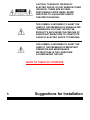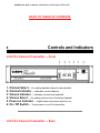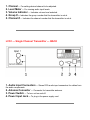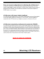
1
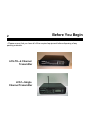
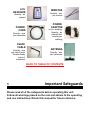
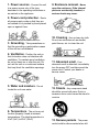
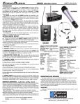
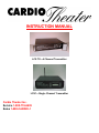
INSTRUCTION MANUAL
LCS TX—4 Channel Transmitter
LCS1—Single Channel Transmitter
Cardio Theater Inc.
Service 1-800-776-6695
Sales 1-800-CARDIO-1
Introduction
1
CONGRATULATIONS on your choice of this product. Its superior sound
reproduction will provide enjoyment and entertainment. We appreciate your patronage
and take pride in the quality components our company produces. Please read this
manual before you install and operate the system. This manual will acquaint you with
operating features and system-connection considerations.
Retain this manual for future reference.
For your records
Record the serial number found on the back of the LCS-TX — 4 Channel
Transmitter or LCS1 — Single Channel Transmitter. Refer to the serial number
whenever you call your dealer for information or service.
Serial Number:________________________
Unpacking
Unpack the units carefully and secure all parts so that none are misplaced.
Examine the units for possible damage. If any damage is noticed, notify your
dealer immediately. If the system was shipped to you, notify the shipping company
without delay. Only the person or company receiving the goods can file a claim
against the carrier for shipping damage. We recommend that you retain the
original carton and packing materials should you need to transport the system in
the future.
TABLE OF CONTENTS
.
.
.
Contents
Before You Begin
Important Safeguards
Suggestions for Installation
Controls and Indicators
System Connections
Receiver Configurations
Attaching LCS Receivers
LCS-TX — 4 Channel Transmitter Setup
LCS-1 — Single Channel Transmitter Setup
LCS Transmitter/Satellite/Cable Configuration
LCS Transmitter/TV Setup
LCS Receiver Setup
Specifications
2
3
5
6
9
10
11
12
13
14
15
16
18
Before You Begin
2
• Please ensure that you have all of the required equipment before disposing of any
packing materials.
LCS-TX—4 Channel
Transmitter
LCS1—Single
Channel Transmitter
LCS
RECEIVER
WIRETIES
Quantity - two
per receiver
Quantity - as
ordered
POWER
ADAPTER
POWER
CORD
(a.k.a.: wallbug)
Quantity - as
ordered (two
wireties per
wallbug)
Quantity - one
per transmitter
CSAFE
CABLE
ANTENNA
Quantity - one
per each Cardio
Theater Ready
piece of
equipment.
Quantity - one
per transmitter
BACK TO TABLE OF CONTENTS
.
.
3
Important Safeguards
Please read all of the safeguards before operating this unit.
Follow all warnings placed on the unit and adhere to the operating
and use instructions. Retain this manual for future reference.
1. Power sources - Connect the unit
9. Enclosure removal - Never
to a power source only of the type
described in the operating instructions or
as marked on the appliance.
open the enclosure. If the internal
parts are accidentally touched, a
serious shock may occur.
2. Power-cord protection - Route
all power-supply cords so that they are
not walked on or pinched by items placed
upon or against them.
10. Cleaning - Use a clean dry cloth.
3. Grounding - Take precautions so
Do not use solvents such as alcohol;
paint thinner, etc. to clean the unit.
that the grounding or polarization means
of the unit are not defeated.
4. Ventilation - Position the unit so
that its location does not interfere with
ventilation. To maintain good ventilation,
do not put items on or over the unit. Do
not use the unit on a cushioned surface
that may block the ventilation openings.
5. Water and moisture - Do not
locate the unit near water.
11. Abnormal smell - If an
abnormal smell is detected, immediately
turn the power OFF and disconnect the
power cord. Contact your dealer or
service center.
12. Stands - Any component stand
should be moved with care. Quick or
excessive force could cause the stand to
overturn
6. Temperature - The unit may not
function properly if used at extreme
temperatures. The ideal temperature is
41oF (5oC) to 87oF (30oC)
13. Nonuse periods - The power
cord should be disconnected when left
7. Heat - The unit should be located
away from heat sources such as
radiators, heat registers, stoves, etc.
8. Electric shock - Care should be
taken so that objects do not fall and liquid
is not spilled on the enclosure. If a metal
object, such as a hairpin or a needle,
comes in contact with the inside of this
unit, a dangerous electric shock may
result.
unused for a long period of time.
14. Damage requiring service The unit should be serviced by a qualified
Cardio Theater technician when:
A. The power cord or the plug has been
damaged;
B. Objects have fallen on, or liquid has
been spilled into the unit;
C. The unit has been exposed to rain;
D. The unit does not appear to operate
normally or exhibits a marked change in
performance;
E. The unit has been dropped or the
enclosure damaged.
15. Servicing - The user should not
attempt to service the unit beyond that
described in this manual. All other
servicing should be referred to a qualified
technician.
Safety Precautions
WARNING:
TO PREVENT FIRE OR ELECTRIC SHOCK, DO NOT
EXPOSE
THIS APPLIANCE TO RAIN OR MOISTURE.
CAUTION: TO REDUCE THE RISK OF
ELECTRIC SHOCK, DO NOT REMOVE COVER
(OR BACK). THERE ARE NO USERSERVICEABLE PARTS INSIDE. REFER
SERVICING TO A QUALIFIED CARDIO
THEATER TECHNICIAN.
THIS SYMBOL IS INTENDED TO ALERT THE
USER TO THE PRESENCE OF UNINSULATED
"DANGEROUS VOLTAGE" WITHIN THE
PRODUCT'S ENCLOSURE THAT MAY BE OF
SIGNIFICANT MAGNITUDE TO CONSTITUTE
A RISK OF ELECTRIC SHOCK TO PERSONS.
THIS SYMBOL IS INTENDED TO ALERT THE
USER TO THE PRESENCE OF IMPORTANT
OPERATING AND MAINTENANCE
INSTRUCTIONS IN THE LITERATURE
ACCOMPANYING THE UNIT.
BACK TO TABLE OF CONTENTS
5
Suggestions for Installation
General Information
●
●
Group the audio components in a single location to minimize cabling in the
cardiovascular room.
If the audio components are stacked in a stereo cabinet, ensure there is adequate
ventilation.
LCS-TX (4 channel)
●
●
●
●
●
Place the LCS transmitter in a well-ventilated area with the front and back easily
accessible.
Place the transmitter antenna eight to twelve feet (8’-12’) from the floor to obtain
the best possible transmission range.
Make sure the antenna is in the vertical position and within line of site to each
receiver.
The range of the LCS transmitter is a line of sight (300-foot diameter) from the
transmitter antenna. (i.e., If you’re within 150 ft. and can physically see the
antenna, you should have good reception.)
Place the transmitter and audio equipment in a central location for best
transmission coverage of the room.
LCS1 (single channel)
●
●
●
●
The LCS1 transmitter may be mounted next to an audio component or TV.
Place the LCS1 transmitter in a well-ventilated area with the front and back easily
accessible.
Make sure the antenna is in the vertical position and within line of site to each
receiver.
The range of the LCS1 transmitter is a line of sight (300-foot diameter) from the
transmitter antenna. (i.e., If you’re within 150 ft. and can physically see the
antenna, you should have good reception.)
LCS Receiver
●
●
●
When attaching LCS Receivers to equipment, take care not to interfere with the
normal operation of the equipment. If the LCS Receiver is connected to a Cardio
Theater ready piece of cardiovascular equipment, the connection should not
interfere with normal operation
If attaching the LCS Receiver to a control panel, avoid covering controls or
indicators.
Attach the LCS Receivers securely with the wire ties provided. You should not be
able to rotate the receiver when it is properly attached. This is very important to
prevent moisture and perspiration from entering the receiver through the
headphone jack or power connector on the back of the unit.
BACK TO TABLE OF CONTENTS
6
Controls and Indicators
LCS-TX 4 Channel Transmitter — Front
1. Channel Select — For setting desired channel to be adjusted.
2. Channel Indicator — Indicates current channel
3. Volume Indicator — Indicates volume level selected.
4. Volume Select — For setting volume level of selected channel.
5. Power-on Indicator — Lights when main power switch is on.
6. On / Off Switch — Turns power on or off to transmitter.
LCS-TX 4 Channel Transmitter — Back
1. Power Input Connector — The power-input connector brings 120 Volts 60 Hz AC
into the system.
2. Main Line Fuse — Main system fuse for the transmitter, 2 Amp 250 Volt Slow-Blow.
3. 120 volt — 220 volt selector switch — Changes input voltage to the
transmitter.
4. Antenna Connector — Connector for transmitter antenna.
5. Audio Input Connectors — Stereo RCA audio input connectors for cables from
audio components.
LCS1 — Single Channel Transmitter — FRONT
1. Channel — For setting desired channel to be adjusted.
2. Level Meter — For viewing audio input levels.
3. Volume Indicator — Indicates volume level selected.
4. Group # — Indicates the group number that the transmitter is set at.
5. Channel # — Indicates the channel number that the transmitter is set at.
LCS1 — Single Channel Transmitter — BACK
1. Audio Input Connectors — Stereo RCA audio input connectors for cables from
the audio components.
2. Antenna Connector — Connector for transmitter antenna.
3. Power Switch — To turn unit on and off.
4. Power Input Jack — To plug in the power supply cord.
LCS Receiver
1. Channel Display — Indicates current channel selected.
2. Channel Select — To select the desired listening channel.
3. Volume Adjust — To select desired listening volume.
4. Mute — Audio mute.
5. Headphone Jack — Standard 3.5mm headphone jack.
BACK TO TABLE OF CONTENTS
.
.
9
System Connections
Transmitters
Note: Make all connections to the TRANSMITTER and Receivers
with Power off.
Step 1
Connect the antenna to the antenna connector on the back of
the LCS-TX — 4 Channel (the LCS1 — Single Channel
Transmitter comes with the antenna already connected).
Step 2
Connect up to four (4) audio components to the stereo input
jacks on the back of the LCS-TX — 4 Channel and one (1)
on the LCS1 — Single Channel.
Step 3
Use the power cord supplied to connect the LCS-TX — 4
Channel or LCS1 — Single Channel to a 120-volt AC outlet.
Step 4
All LCS volumes should not be more than 68 and not be
less than 48 on the transmitters.
Step 5
ALL TV’s need external speakers off, not muted. Adjust
volumes accordingly. (See page 12 "audio level setup" for
more information).
BACK TO TABLE OF CONTENTS
.
.
10
Receiver Configurations
There are two (2) configurations for attaching the LCS Receivers.
Contact the manufacturer of the cardiovascular equipment to determine if the unit is
Cardio Theater ready or can be retro-fitted, or call the Cardio Theater Service Center for
assistance (800-776-6695). This will determine whether we send power adapters or
CSAFE cables for your system.
LCS Receiver with power adapter (wallbug)
For cardiovascular equipment that is not Cardio Theater ready, power must be supplied
via a power adapter (wallbug) connected to a 120-volt outlet. The power adapter is
connected to the LCS Receiver by a telephone connector on the back of the unit.
LCS Receiver powered by cardiovascular equipment (CSAFE)
For cardiovascular equipment that is Cardio Theater ready, power will be supplied via a
connector located on the cardiovascular equipment. The LCS Receiver is powered from
the machine via an adapter cable that plugs into the receiver and into the cardiovascular
piece. There are different adapter cables available for most cardiovascular machines on
the market. Your sales person will need to know the make and model of each piece of
cardiovascular equipment that will be cardio theater ready or retro-fittable (if you plan to
retro-fit) at the time of the purchase of the Cardio Theater system.
BACK TO TABLE OF CONTENTS
.
.
11
Attaching LCS Receivers
The LCS Receiver can be
attached to virtually any
piece of equipment.
For equipment with round handles
or railing, LCS Receivers are
supplied with a built-in mounting
block.
●
●
Align the LCS Receiver on
the handle or rail as shown.
Use two of the supplied
plastic wire ties to attach
the LCS Receiver to the
handle or rail. Pull wire ties
firmly to secure and cut off
the excess.
This method may be used to mount a
LCS Receiver either horizontally or
vertically.
This is the preferred method of
attaching the LCS Receiver to
minimize interference with control
panels and displays.
For equipment with flat control
panels and no hand rails, Super
Lock (a form of super strong
Velcro) may be used.
●
●
●
Determine the best
mounting position.
Clean the mounting surface
thoroughly.
Remove the protective
cover from the adhesive
strip.
Position the LCS Receiver and press
firmly for the adhesive to grip.
CAUTION: When attaching to a
control panel, care should be taken
to avoid blocking access to controls
or illustrations.
BACK TO TABLE OF CONTENTS
.
.
12
LCS-TX — 4 Channel Transmitter Setup
Programming LCS-TX — 4 Channel Transmitter
NOTE: These instructions are for LCS Transmitters with Software version 1.01 and
higher. To determine the software version of your transmitter, power the unit on. The
group number will display for 2 seconds, and then the software version will display for 2
seconds before the unit enters normal operating mode. If the unit does not display this
information, you have a previous version. You should contact the Cardio Theater Service
Center for technical assistance (800) 776-6695.
Set to U.S. mode:
Press channel down and volume down while powering the unit on — display shows
"1776" until released. Then it displays the software version, then enters normal operation
showing the group # on the left side of the display and the channel # on the right.
Set to Australian mode (if using in Australia only):
Press channel up and volume up while powering the unit on — display shows "1901" until
released. Then it displays the software version, then enters normal operation showing the
group # on the left side of the display and the channel # on the right.
Setting the Group:
Press volume up and volume down while powering the unit on — Display shows "01".
Release volume up and volume down buttons. Use the channel select buttons to scroll to
the desired group (1-13). Press volume down to lock the group into memory. Display will
show the software version for 2 seconds then returns to normal operation. Repeat for
each additional transmitter. Ensure that a different group is selected for each transmitter.
Audio Level Setup:
After connecting audio components to the transmitter, turn on the transmitter and all
audio equipment (make sure all audio components are playing music and/or tuned to the
desired station).
Adjust the volume level at the transmitter so that the LED’s are in the green by pressing
the volume up/down button on the transmitter. Occasional yellow is okay, but should
never by in the red. Press the channel up/down button on the transmitter and adjust all
channels for proper audio level.
NOTE: When adjusting audio levels on televisions with variable audio out (i.e.,
volume level to Cardio Theater transmitter changes when volume is adjusted), it is
best to first set the volume level on the transmitter display to "56". Then adjust the
audio level on the television until the transmitter LED’s are in the green. It is
important not to let your customers change the volume on the televisions. Poor
and/or distorted audio will result.
BACK TO TABLE OF CONTENTS
.
.
13
LCS1 — Single Channel Transmitter
Setup
Programming LCS1 — Single Channel Transmitter
Set to U.S. mode:
Press channel down and volume down while powering the unit on — display shows
"1776" until released. Then it displays the software version, then enters normal operation
showing the group # on the left side of the display and the channel # on the right.
Set to Australian mode (if using in Australia only):
Press channel up and volume up while powering the unit on — display shows "1901" until
released. Then it displays the software version, then enters normal operation showing the
group # on the left side of the display and the channel # on the right.
To set the group:
Use channel up and down to set the desired group and channel #. The group will be
shown on the left side of the display. The channel of that group will be displayed on the
right hand side of the display. See the picture on page 6 of the manual.
If you are using the LCS1 in conjunction with existing 4 channel
LCS units:
Determine the group numbers being used by the existing 4 channel LCS units by cycling
power off and on while watching the display. Observe the group number on power up. Do
this for each LCS transmitter, noting the groups being used.
Set the LCS1 to channel 1 of any unused group. (i.e., If groups 1, 3 & 4 are currently in
use by other transmitters, set the LCS1 to group 2, channel 1 or group 5, channel 1).
If you are installing more than 1 LCS1 transmitter:
Whether with existing transmitters or not, always set the first unit to channel 1 of an
unused group and the next unit to channel 2 of that same group, etc., until all four
channels are used for that group.
Example: First LCS1 set to Group 1, Channel 1,
Second LCS1 set to Group 1, Channel 2
Third LCS1 set to Group 1, Channel 3, etc.
BACK TO TABLE OF CONTENTS
.
.
14
LCS Transmitter/Satellite/
Cable Configuration
IF YOU DECIDE TO USE SATELLITE:
The same configuration applies if you are using cable/satellite music
receivers.
BACK TO TABLE OF CONTENTS
.
.
15
LCS Transmitter/TV Setup
FRONT
Remember to shut off the television's external speakers.
BACK
BACK TO TABLE OF CONTENTS
.
.
16
LCS Receiver Setup
Programming LCS Receivers
Before programming the LCS Receivers, ensure all transmitters are turned on and
programmed. Receivers should be at least 10 feet from the transmitters before the
programming process begins.
NOTE: These instructions are for LCS Receivers with Software version 13 and higher. To
determine the software version of your LCS Receiver, power the unit on while holding the
channel down and volume down buttons. The display will show "76" until the buttons are
released. If the unit does not display this information, you have a previous version and
you should contact the Cardio Theater Service Center for assistance (800) 776-6695.
Set to U.S. mode:
Press channel down and volume down while powering the unit on — display shows "76"
until released, then enters normal operating mode.
Set to Australian mode. (if using in Australia only):
Press channel up and volume up while powering the unit on — display shows "01" until
released, then enters normal operating mode
Auto Programming:
Attach power source to the back of the receiver (wallbug or CSAFE cable). Press and
hold the mute button while plugging in headphones. When the display shows a dash "-"
release the mute button. Programming is complete when the number one "1" appears in
the display. Auto programming takes approximately one and a half minutes per unit.
NOTE: If there are other wireless devices within the club, auto programming may not
work properly. If auto programming does not work, proceed to manual programming
instructions.
Manual Programming:
Attach a power source to the back of the receiver (wallbug or CSAFE cable). Press and
hold the volume up and volume down buttons while plugging in headphones. When the
display shows "1", release volume buttons. Use the channel buttons to scroll to the
frequency number (1 through 52) associated with the group number the transmitter(s) is/
are set to. Refer to the chart below. Press the volume down button to lock this frequency
into memory. Use the channel buttons to scroll to the next desired frequency and again
press the volume down button. Continue selecting frequencies pressing volume down
after each one until all frequencies have been selected. Press volume up to complete
manual programming. Display shows "1" indicating manual programming is complete and
the unit has returned to normal operation.
Example: If you are using a four channel transmitter that is set to group 3*, and an LCS1
single channel transmitter that is set to group 5, channel 2, you would select frequencies
9, 10, 11, 12 & 18. Press volume down after selecting each frequency and volume up to
lock the information into memory. Your LCS receivers will now scroll 1 through 5 in
normal operating mode.
A four-channel transmitter automatically includes all four (4) channels within the
selected group.
GroupChannel
#
Freq. #
GroupChannel
#
Freq. #
1-1
1
7-3
27
1-2
2
7-4
28
1-3
3
8-1
29
1-4
4
8-2
30
2-1
5
8-3
31
2-2
6
8-4
32
2-3
7
9-1
33
2-4
8
9-2
34
3-1
9
9-3
35
3-2
10
9-4
36
3-3
11
10 - 1
37
3-4
12
10 - 2
38
4-1
13
10 - 3
39
4-2
14
10 - 4
40
4-3
15
11 - 1
41
4-4
16
11 - 2
42
5-1
17
11 - 3
43
5-2
18
11 - 4
44
5-3
19
12 - 1
45
5-4
20
12 - 2
46
6-1
21
12 - 3
47
6-2
22
12 - 4
48
6-3
23
13 - 1
49
6-4
24
13 - 2
50
7-1
25
13 - 3
51
7-2
26
13 - 4
52
BACK TO TABLE OF CONTENTS
.
.
Specifications
18
LCS-TX — 4 Channel Transmitter
Transmission Frequency Range
Frequency Range
903.6 MHz to 926.2 MHz
52 channels, adjustable from 905 MHz to
925 MHz.
Transmission Power
95 dbmv max.
Transmission Range
150 ft. from antenna
Power Consumption
25 watts max.
Audio Inputs
Dimensions
Weight
4
W: 19.00" / 48.26cm
H: 3.87" / 9.83 cm
D: 14.75" / 37.46 cm
7.5 lbs. / 3.4 kg
LCS1 — Single Channel Transmitter
Transmission Frequency Range
Frequency Range
905MHz to 925 MHz
52 channels, adjustable from 905 MHz to
925 MHz.
Transmission Power
95 dbmv max.
Transmission Range
150 ft.
Power Consumption
10 watts max.
Audio Inputs
Dimensions
1
W: 8.062" / 20.3 cm
H: 2.125" / 5.41 cm
D: 6.25" / 15.8 cm
Weight
2.41 lbs. / 1.09 kg
Output Level / Load Impedance
550 mV / 32 Ohm.
Dimensions
W: 2.55" / 6.48 cm
H: 3.93" / 9.98 cm
D: 0.97" / 2.46 cm
LCS Receiver
Weight
3 oz / 85 g
Regulatory Information
FCC Compliance and Advisory Statement
This device complies with Part 15 of the FCC Rules. Operation is subject to the following
two conditions: 1) this device may not cause harmful interference, and 2) this device must
accept any interference received, including interference that may cause undesired
operation.
This equipment has been tested and found to comply with the limits for a Class B digital
device, pursuant to Part 15 of the FCC Rules. These limits are designed to provide
reasonable protection against harmful interference in a residential installation.
This equipment generates, uses, and can radiate radio frequency energy, and if not
installed or used in accordance with the instructions, may cause harmful interference to
radio communications. However, there is no guarantee that interference will not occur in
a particular installation.
If this equipment does cause harmful interference to radio or television reception, which
can be determined by turning the equipment off and on, the user is encouraged to try to
correct the interference by one or more of the following measures: 1) reorient or relocate
the receiving antenna; 2) increase the separation between the equipment and the
receiver; 3) connect the equipment to an outlet on a circuit different from that to which the
receiver is connected; 4) consult the dealer or an experienced radio/TV technician for
additional suggestions.
Any changes or modifications not expressly approved by the party responsible for
compliance could void the user's authority to operate the equipment. Where shielded
interface cables have been provided with the product or specified additional components
or accessories elsewhere defined to be used with the installation of the product, they
must be used in order to ensure compliance with FCC regulations.
Note: Cardio Theater follows a policy of continuous advancements in development.
For this reason, specifications may be changed without notice.
For questions regarding
any specifications, please call
the Cardio Theater Service Center at
(800) 776-6695.
BACK TO TABLE OF CONTENTS