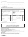
1
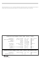
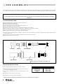
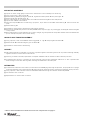
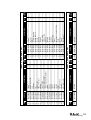
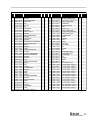
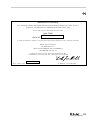
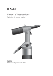
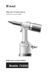
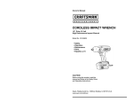
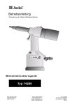
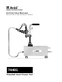
Instruction Manual
Pass onto user to read and keep for reference
74401
Threaded Insert Power Tool
Avdel UK Limited policy is one of continuous development. Specifications shown in this document may be subject to
changes which may be introduced after publication. For the latest information always consult Avdel.
SPECIFICATIONS
AIR PRESSURE ■
FREE AIR VOLUME REQUIRED ■
FOR
THE
Minimum - Maximum
@ 5 bar or 75 lbf/in
STROKE ■
2
Maximum
MOTOR SPEED ■
SPIN ON
SPIN OFF
PULL FORCE ■
@ 5 bar or 75 lbf/in 2
CYCLE TIME ■
Approximately
NOISE LEVEL ■
Less than
WEIGHT ■ w/o nose equipment or hose
VIBRATION ■
SPECIFICATIONS
Less than
FOR
THE
AIR PRESSURE ■
Minimum - Maximum
INTENSIFICATION RATIO ■
51:1
74401
■ 4 - 7 bar
■ 15 litres
■ 12 mm
■ 2500 RPM
■ 3000 RPM
■ 35.93 kN
■ 3 seconds
■ 70 dB(A)
■ 2 kg
■ 2.5 m/s 2
74401
■ 60 - 100 lbf/in 2
■ .525 ft 3
■ .47 in
■
■
■ 8077 lbf
■
■
■ 4.4 lb
■
INTENSIFIER
■ 4 - 7 bar
■
TOOL
■ 60 - 100 lbf/in 2
■
CONTENTS
SAFETY
General
2
Specific to Type of Tool
3
General
4
Tool Dimensions
4
Air Supply
5
Stroke Adjustment
5
Operating Procedure
6
Connnecting the Foot Pedal
7
Fitting
8
Servicing
8
Components
9
INTENT OF USE
PUTTING INTO SERVICE
NOSE ASSEMBLIES
SERVICING
Regular Servicing
10
Service Kit
10
Maintenance
11-13
General Assembly & Parts List
14-20
PRIMING
FAULT
Priming Oil Details
22
Priming Procedure
22
Fault Diagnosis Table
23
DIAGNOSIS
1
S AFETY
This instruction manual must be read with particular attention to the following safety rules,
by any person installing, operating, or servicing this tool.
DO NOT USE OUTSIDE THE DESIGN INTENT.
DO NOT USE EQUIPMENT WITH THIS TOOL/MACHINE OTHER THAN THAT
RECOMMENDED AND SUPPLIED BY AVDEL.
ANY MODIFICATION UNDERTAKEN BY THE CUSTOMER TO THE TOOL/MACHINE,
NOSE ASSEMBLIES, ACCESSORIES OR ANY EQUIPMENT SUPPLIED BY AVDEL OR THEIR
REPRESENTATIVES, SHALL BE THE CUSTOMER'S ENTIRE RESPONSIBILITY. AVDEL WILL BE
PLEASED TO ADVISE UPON ANY PROPOSED MODIFICATION.
THE TOOL/MACHINE MUST BE MAINTAINED IN A SAFE WORKING CONDITION AT
ALL TIMES AND EXAMINED AT REGULAR INTERVALS FOR DAMAGE AND FUNCTION BY
TRAINED COMPETENT PERSONNEL. ANY DISMANTLING PROCEDURE SHALL BE
UNDERTAKEN ONLY BY PERSONNEL TRAINED IN AVDEL PROCEDURES. DO NOT DISMANTLE
THIS TOOL/MACHINE WITHOUT PRIOR REFERENCE TO THE MAINTENANCE INSTRUCTIONS.
CONTACT AVDEL WITH YOUR TRAINING REQUIREMENTS.
THE TOOL/MACHINE SHALL AT ALL TIMES BE OPERATED IN ACCORDANCE WITH
RELEVANT HEALTH AND SAFETY LEGISLATION. IN THE U.K. THE “HEALTH AND SAFETY AT
WORK ETC. ACT 1974” APPLIES. ANY QUESTION REGARDING THE CORRECT OPERATION
OF THE TOOL/MACHINE AND OPERATOR SAFETY SHOULD BE DIRECTED TO AVDEL.
THE PRECAUTIONS TO BE OBSERVED WHEN USING THIS TOOL/MACHINE MUST BE
EXPLAINED BY THE CUSTOMER TO ALL OPERATORS.
ALWAYS DISCONNECT THE AIRLINE FROM THE TOOL/MACHINE INLET BEFORE
ATTEMPTING TO ADJUST, FIT OR REMOVE A NOSE ASSEMBLY.
DO NOT OPERATE A TOOL/MACHINE THAT IS DIRECTED TOWARDS ANY PERSON(S).
ALWAYS ADOPT A FIRM FOOTING OR A STABLE POSITION BEFORE OPERATING THE
TOOL/MACHINE.
ENSURE THAT VENT HOLES DO NOT BECOME BLOCKED OR COVERED AND THAT
HOSES ARE ALWAYS IN GOOD CONDITION.
2
In addition to the general safety rules opposite, the following specific safety points must also
be observed:
THE OPERATING PRESSURE SHALL NOT EXCEED 7 BAR - 100 LBF/IN 2 .
DO NOT OPERATE THE TOOL WITHOUT FULL NOSE EQUIPMENT, OIL PLUG AND OIL
BLEED SCREW IN PLACE.
WHEN USING THE TOOL, THE WEARING OF SAFETY GLASSES IS REQUIRED BOTH BY
THE OPERATOR AND OTHERS IN THE VICINITY TO PROTECT AGAINST FASTENER
PROJECTION, SHOULD A FASTENER BE PLACED ‘IN AIR’. WE RECOMMEND WEARING
GLOVES IF THERE ARE SHARP EDGES OR CORNERS ON THE APPLICATION.
TAKE CARE TO AVOID ENTANGLEMENT OF LOOSE CLOTHES, TIES, LONG HAIR,
CLEANING RAGS ETC… IN THE MOVING PARTS OF THE TOOL WHICH SHOULD BE KEPT
DRY AND CLEAN FOR BEST POSSIBLE GRIP.
WHEN CARRYING THE TOOL FROM PLACE TO PLACE KEEP HANDS AWAY FROM THE
TRIGGER/LEVER AND EMERGENCY SPIN-OFF BUTTON TO AVOID INADVERTENT START
UP.
EXCESSIVE CONTACT WITH HYDRAULIC OIL SHOULD BE AVOIDED. TO MINIMIZE THE
POSSIBILITY OF RASHES, CARE SHOULD BE TAKEN TO WASH THOROUGHLY.
3
I NTENT
OF USE
The hydro-pneumatic 74401 tool is designed to place Avdel threaded inserts at high speed making it ideal for batch or flow-line
assembly in a wide variety of applications throughout all industries.
Use the selection chart page 7 to select a complete tool.
It is also possible to order the handle with no hoses, part number 74401-12000, or the cabinet only, part number 07265-03201.
Other items include :
74401-01000
74401-13500
74401-13900
74401-13000
Basic tool with 5m hose assembly
Hose assembly (5m)
Complete cabinet without intensifier
Complete cabinet with intensifier
55
1.96
100
3.93
80
3.14
27
1.06
170
6.7
400
15.74
5000
196.85
250
9.84
500
19.68
Dimensions shown in bold are millimetres. Other dimensions are in inches.
4
AIR
SUPPLY
PUTTING
INTO SERVICE
All tools are operated with compressed air at an optimum pressure of 5.5 bar. We recommend the use of pressure regulators and
automatic oiling/filtering systems on the main air supply. These should be fitted within 3 metres of the tool (see diagram below) to ensure
maximum tool life and minimum tool maintenance.
Air supply hoses should have a minimum working effective pressure rating of 150% of the maximum pressure produced in the system
or 10 bar, whichever is the highest. Air hoses should be oil resistant, have an abrasion resistant exterior and should be armoured where
operating conditions may result in hoses being damaged. All air hoses MUST have a minimum bore diameter of 6.4 mm or 1/ 4 inch.
Read servicing daily details page 10.
3
STOP COCK
(USED DURING MAINTENANCE
OF FILTER/REGULATOR
OR LUBRICATION UNITS)
TRES MAXIMUM
ME
0 2 4
1416
12
6 8 10
LUBRICATOR
TAKE OFF
POINT FROM
MAIN SUPPLY
MAIN SUPPLY
DRAIN POINT
PRESSURE REGULATOR
AND FILTER
(DRAIN DAILY)
STROKE
ADJUSTMENT
This adjustment is necessary to ensure optimum insert deformation.
It is suggested, therefore, that a test plate with the same thickness
and hole size as workpiece be used.
If deformation is insufficient, the insert will rotate inside the
application.
If deformation is excessive, thread distortion will occur and
possibly drive screw fracture.
The stroke is adjusted by the amount the stroke adjustment locknut
12, (parts list page 15), is screwed in or out. To shorten stroke,
screw in; to lengthen stroke, unscrew the rear casing. Adjust until
optimum deformation is obtained.
5
OPERATING
■
■
■
■
PROCEDURE
Connect tool to air supply.
Offer up insert, lip first to drive screw. A light pressure will start the motor and automatically thread the insert up against nose and
stop.
Insert fastener into application squarely.
Fully depress trigger. This will both place insert into the application and reverse it off the drive screw.
ACCESSORIES
Two different accessories are available :
COMBINED HANDLE & HOLSTER
2
1
Refer to the illustration opposite for details.
■
■
■
■
■
■
Using the base 6 as a guide, spot through and drill four
5.5mm diameter holes in the position required on the cabinet
lid.
Place plate 12 on the inside of the cabinet lid.
Place base 6 on the outside of the cabinet and using screws 7,
screw the base / cabinet lid / and plate in position.
Insert tube with hook 2 into the holster 4 and secure the holster
4 in position by tightening bolt 3 into nut 5.
Insert tube and holster into base 6 and lock into position by
tightening bolt 8 into bolt 5.
Drill two 5.5mm holes, one at either end of the cabinet lid and
secure clips 10 in position with 5mm bolts 9.
4
3
5
6
5
07265-09500 PARTS LIST
ITEM
PART Nº
1
2
3
4
5
6
7
8
9
10
11
07265-09501
07265-09502
07265-09504
07265-09503
07265-09505
07265-09508
07265-09507
07265-09506
07265-09512
07265-09511
07265-09509
6
DESCRIPTION
RUBBER HANDLE
TUBE WITH HOOK
M5 BOLTS
HOLSTER
M5 NUTS
BASE
M5 BOLT
M5 BOLT
M5 BOLT
CLIPS
PLATE
1
1
2
1
3
1
4
1
2
2
1
-
9
7
QTY SPARES
8
10
9
10
11
CONNECTING THE FOOT PEDAL
■
■
■
■
Please refer to the illustration for details.
Disconnect the tool from the air supply.
Open base 53.
Identify valve 27 connected to the air pressure regulator
48 (point F on GA, page 16).
Disconnect the 4mm output hose which feeds the tool
trigger (hose 68, page 18).
Connect 4mm air hose 4 to valve 27.
Connect the Y connector to air hose 4.
To one side of the Y connector, connect the hose from the
tool trigger.
To the other side of the Y connector, connect air hose 2.
Connect air hose 2 to the foot pedal.
Close base 53 and reconnect air supply.
Tool can now be operated with the foot pedal or the trigger
and the emergency spin-off button 44 is still operable.
■
■
■
■
■
■
■
■
4
3
2
FROM
TRIGGER
74401-13800 PARTS LIST
ITEM
PART Nº
1
2
3
4
07005-00077
74401-13801
74401-13027
74401-13095
DESCRIPTION
FOOT PEDAL
4mm AIR HOSE (1000mm)
'Y' CONNECTOR
4mm AIR HOSE (250mm)
QTY SPARES
1
1
1
1
-
1
7
NOSE
ASSEMBLIES
It is essential that the correct nose assembly is fitted prior to operating the tool. By knowing your original complete tool part number
or the details of the fastener to be placed, you will be able to order a new complete nose assembly using the selection tables on page 9.
IMPORTANT
The air supply must be disconnected when fitting or removing nose assemblies unless specifically instructed
otherwise.
FITTING INSTRUCTIONS
■
■
■
■
■
■
■
■
■
If still fitted remove the nose casing and the adaptor nut.
Insert drive shaft 4 into spindle.
Fit drive screw 3 onto drive shaft 4.
Insert reducing sleeve 5 (if required) into the adaptor nut.
Screw the adaptor nut onto the spindle.
Hold the spindle with a spanner* and tighten the adaptor nut clockwise.
While holding the adaptor nut with the spanner*, tighten the lock nut anti-clockwise.
Screw on the nose casing and nose tip 1 with the nose tip lock nut.
The reverse operation is carried out for equipment removal.
■
With tool still disconnected from air supply, screw one insert onto drive screw manually - making sure the insert is flush with the
end of drive screw.
Set nose tip in exact position and lock nose tip nut clockwise with a spanner*.
Remove the insert from drive screw.
■
■
4
LOCK NUT
SPINDLE
3
5
FRICTION RING
2
ADAPTOR NUT
1
NOSE CASING
l
Items in grey are included in the base tool.
SERVICING INSTRUCTIONS
Nose assemblies should be serviced at weekly intervals.
■
■
Remove the complete nose assembly using the reverse procedure to the ‘Fitting Instructions’.
Any worn or damaged part should be replaced by a new
part.
Particularly check wear on drive screw.
■
Assemble according to fitting instructions.
■
ALTERNATIVE ITEMS REQUIRED TO PLACE M12 FASTENERS
ADAPTOR NUT
74401-12028
FRICTION RING
74401-12029
SPINDLE
74401-12030
* refers to items included in the Avdel service kit. For complete list see page 11.
8
NOSE ASSEMBLY COMPONENTS
Nose tips vary in shape according to the insert type. Each nose assembly represents a unique assembly of components which can be
ordered individually. All nose assemblies also include a nose tip locknut (part number 07555-00901). Component numbers refer to
the illustration on the opposite page. We recommend some stock as items will need regular replacement. Read the Nose Assemblies
servicing instructions opposite carefully.
INSERT
SIZE
COMPLETE TOOL
NOSE ASSEMBLY
1
3
4
5
LARGE FLANGE INSERTS (9408,9418,GK08,T.S.N.) + STANDARD NUTSERT + SQUARESERT + L.F. HEXSERT (OPEN AND CLOSED END)
M3
74401-00083
07555-09883
07555-00903
07555-09003
07555-01003
07555-09103
M4
74401-00084
07555-09884
07555-00904
07555-09004
07555-01004
07555-09104
• M5
74401-00485
07555-09185
07555-00915
07555-09005
07555-01005
07555-09105
M5
74401-00085
07555-09885
07555-00905
07555-09005
07555-01005
07555-09105
M6
74401-00086
07555-09886
07555-00906
07555-09006
07555-01006
07555-09106
M8
74401-00088
07555-09888
07555-00908
07555-09008
07555-01008
07555-09108
M10
74401-00080
07555-09880
07555-00910
07555-09010
07555-01010
–
4 UNC
74401-00054
07555-09854
07555-00854
07555-09054
07555-00754
07555-09154
6 UNC
74401-00056
07555-09856
07555-00856
07555-09056
07555-00756
07555-09156
8 UNC
74401-00058
07555-09858
07555-00858
07555-09058
07555-00758
07555-09158
10 UNC
74401-00050
07555-09850
07555-00850
07555-09050
07555-00750
07555-09150
1/4 UNC
74401-00048
07555-09848
07555-00848
07555-09048
07555-00748
07555-09148
5/16 UNC
74401-00040
07555-09840
07555-00840
07555-09040
07555-00740
07555-09140
3/8 UNC
74401-00042
07555-09842
07555-00842
07555-09042
07555-00742
–
74401-00070
07555-09870
10 UNF
07555-00850
07555-09070
07555-00750
07555-09150
1/4 UNF
74401-00068
07555-09868
07555-00848
07555-09068
07555-00748
07555-09148
5/16 UNF
74401-00060
07555-09860
07555-00840
07555-09060
07555-00740
07555-09140
3/8 UNF
74401-00062
07555-09862
07555-00842
07555-09062
07555-00742
–
THIN SHEET NUTSERT ( OPEN AND CLOSED END )
M3
M4
M5
M6
M8
M10
4 UNC
6 UNC
8 UNC
10 UNC
1/4 UNC
5/16 UNC
10 UNF
1/4 UNF
5/16 UNF
74401-00183
74401-00184
74401-00185
74401-00186
74401-00188
74401-00180
74401-00154
74401-00156
74401-00158
74401-00150
74401-00148
74401-00140
74401-00170
74401-00168
74401-00160
07555-09983
07555-09984
07555-09985
07555-09986
07555-09988
07555-09980
07555-09954
07555-09956
07555-09958
07555-09950
07555-09948
07555-09940
07555-09970
07555-09968
07555-09960
M3
M4
M5
M6
M8
8 UNC
10 UNC
1/4 UNC
8 UNF
10 UNF
1/4 UNF
74401-00283
74401-00284
74401-00285
74401-00286
74401-00288
74401-00258
74401-00250
74401-00248
74401-00278
74401-00270
74401-00268
07555-09583
07555-09584
07555-09585
07555-09586
07555-09588
07555-09558
07555-09550
07555-09548
07555-09578
07555-09570
07555-09568
M3
M4
M5
M6
M8
74401-00683
74401-00684
74401-00685
74401-00686
74401-00688
07555-09283
07555-09284
07555-09285
07555-09286
07555-09288
07555-08103
07555-08104
07555-08105
07555-08106
07555-08108
M12
** M12
-
-
07555-00912
07555-00992
07555-00993
07555-00994
07555-00995
07555-00996
07555-00998
07555-00999
07555-00954
07555-00956
07555-00958
07555-00950
07555-00948
07555-00940
07555-00950
07555-00948
07555-00940
07555-09003
07555-09004
07555-09005
07555-09006
07555-09008
07555-09010
07555-09054
07555-09056
07555-09058
07555-09050
07555-09048
07555-09040
07555-09070
07555-09068
07555-09060
07555-01003
07555-01004
07555-01005
07555-01006
07555-01008
07555-01010
07555-00754
07555-00756
07555-00758
07555-00750
07555-00748
07555-00740
07555-00750
07555-00748
07555-00740
07555-09103
07555-09104
07555-09105
07555-09106
07555-09108
–
07555-09154
07555-09156
07555-09158
07555-09150
07555-09148
07555-09140
07555-09150
07555-09148
07555-09140
07555-01003
07555-01004
07555-01005
07555-01006
07555-01008
07555-00758
07555-00750
07555-00748
07555-00758
07555-00750
07555-00748
07555-09103
07555-09104
07555-09105
07555-09106
07555-09108
07555-09158
07555-09150
07555-09148
07555-09158
07555-09150
07555-09148
07555-09003
07555-09004
07555-09005
07555-09006
07555-09008
07555-01003
07555-01004
07555-01005
07555-01006
07555-01008
07555-09103
07555-09104
07555-09105
07555-09106
07555-09108
74401-09012
74401-09012
07555-01012
07555-01012
-
SUPERSERT - OPEN AND CLOSED END
07555-07103
07555-07104
07555-07105
07555-07106
07555-07108
07555-07158
07555-07150
07555-07148
07555-07158
07555-07150
07555-07148
07555-09003
07555-09004
07555-09005
07555-09006
07555-09008
07555-09058
07555-09050
07555-09048
07555-09078
07555-09070
07555-09068
HEXSERT ( OPEN AND CLOSED END )
ABOVE M12
•
**
Places M5 large flange Thin Sheet Nutsert 09698-00516 ONLY
Thin Sheet only
9
SERVICING
THE TOOL
Regular servicing should be carried out and a comprehensive inspection performed annually or every 500000 cycles, whichever is
sooner.
IMPORTANT
The employer is responsible for ensuring that tool maintenance instructions are given to the appropriate personnel.
The operator should not be involved in maintenance or repair of the tool unless properly trained.
DAILY
■
Daily, before use or when first putting the tool into service, pour a few drops of clean, light lubricating oil into the air inlet of the
tool if no lubricator is fitted on air supply. If the tool is in continuous use, the air hose should be disconnected from the main air
supply and the tool lubricated every two to three hours.
■
Check for air leaks. If damaged, hoses and couplings should be replaced by new items.
■
If there is no filter on the pressure regulator, bleed the air line to clear it of accumulated dirt or water before connecting air hose
to tool.
■
Check that the nose assembly is correct.
■
Check the stroke of the tool is adequate to place selected insert. (see stroke adjustment page 5).
■
Inspect the drive screw in the nose assembly for wear or damage. If any, renew.
WEEKLY
■
Check for oil leaks and air leaks on air supply hose and fittings.
For all servicing we recommend the use of the service kit, part number 74401-13800, and the combination spanner kit, part number
74401-99993.
SERVICE KIT
ITEM PART Nº
07900-00618
07900-00639
07900-00640
07900-00641
COMBINATION SPANNER KIT
DESCRIPTION
PUSHER
NYLON BUSH
METAL BUSH
BULLET
Nº OFF
ITEM PART Nº
1
1
1
1
07900-00409
07900-00632
07900-00426
07900-00624
74200-12196
07900-00642
07900-00224
DESCRIPTION
12mm/13mm SPANNER
17mm/19mm SPANNER
COMBINATION SPANNER
4mm PIN PUNCH
17mm THIN SPANNER
27mm/30mm SPANNER
4mm ALLEN KEY
Grease used during tool maintenance can be ordered as a single item, the part number is shown in the service kit above.
MOLY
LITHIUM
GREASE
FIRST AID
SKIN: As the grease is completely water resistant it is best
removed with an approved emulsifying skin cleaner.
INGESTION: Make the individual drink 30ml Milk of
Magnesia, preferably in a cup of milk.
EP
3753
S A F E T Y
FIRE
FLASH POINT: Above 220°C.
Not classified as flammable.
Suitable extinguishing media: CO 2, Halon or water spray
if applied by an experienced operator.
EYES: Irritant but not harmful. Irrigate with water and
seek medical attention.
HANDLING
Use barrier cream or oil resistant gloves
ENVIRONMENT
Scrape up for burning or disposal on approved site.
STORAGE
Away from heat and oxidising agent.
10
D A T A
Nº OFF
1
2
1
1
1
1
1
MAINTENANCE
Every 500000 cycles the tool should be completely dismantled and components replaced where worn, damaged or when recommended.
All ‘O’ rings and seals should be replaced with new ones and lubricated with Moly Lithium grease EP 3753 before assembling.
IMPORTANT
Safety Instructions appear on pages 2 & 3.
The employer is responsible for ensuring that tool maintenance instructions are given to the appropriate personnel.
The operator should not be involved in maintenance or repair of the tool unless properly trained.
The airline must be disconnected before any servicing or dismantling is attempted unless specifically instructed otherwise.
It is recommended that any dismantling operation be carried out in clean conditions.
Item numbers in bold refer to the handle assembly drawing and parts list, pages 14 - 15.
Prior to dismantling the tool it is necessary to remove the nose assembly. For simple removal instructions see the nose assemblies section,
pages 8 - 9.
Remove bleed screw 32 and washer 31 and drain oil from tool.
For total tool servicing we advise that you proceed with dismantling of sub-assemblies in the order shown below.
To disconnect the oil hose 46 and air delivery and return hoses 45 from the tool, disengage spiral protection sleeve 47 from sleeve 39
and lower sleeve 39 to gain access to the hoses. Disconnect air hoses by pushing and releasing the quick release connectors. Using
two spanners, undo oil hose 46 at connector 38 leaving the connector attached to the handle of the tool. Remove the tool.
Remove the nose equipment from the tool by loosening the nose tip locknut and unscrewing the nose tip. Unscrew nose casing 33, and
with the aid of spanners* remove the components of the nose assembly. Remove the two air tubes 48 from connectors 1.
HEAD ASSEMBLY
■
■
■
■
Using the pins of the combination spanner*, unscrew stroke adjustment locknut 12.
Withdraw stroke adjustment locknut 12, air motor casing 3, spring 13, movement pivot 22, shim adjustment ring 23, piston 24 and
lip seal 25.
Grip the flats on the air motor casing 3 in a vice fitted with soft jaws and with a spanner* separate the air motor assembly from
the piston 24. Spring 13 and stroke adjustment locknut 12 can now be removed from air motor casing 3.
Using circlip pliers* remove circlip 26 and extract lip seal 46.
From the air motor casing 3 remove centre connector 1 using an Allen key* and extract spring 2, ball 4 and pushrod 5.
■
■
■
■
■
■
■
Reassemble in reverse order of dismantling, observing the following:
Use nylon bush* and pusher* to fit lip seal 46 into its housing.
Use circlip pliers* to fit circlip 26.
Insert metal bush* into handle 28.
Fit lip seal 25 onto piston 24.
Screw bullet* onto piston 24 to ease insertion of lip seal 25 into the handle.
Insert piston 24 into the handle through the metal bush*, then remove the bush* and bullet* from piston.
■
* refers to items included in the Avdel service kit. For complete list see page 10.
11
AIR MOTOR ASSEMBLY
■
■
■
■
■
■
■
■
■
■
■
Tap the air motor casing gently on the bench to remove the air motor assembly from the casing.
Using circlip pliers*, remove circlip 14.
Remove bearing 15 and planet gear spindle 11, together with three planets 16 from planet gear 10.
Remove planet gear 10 and spacer 17.
Using a soft mallet, tap on splined head of rotor 19 and remove bearing 9 and front end plate 8.
Tap out rotor 19 and rotor blades 7.
Place rear end plate 20 in the vice and using a pin punch*, tap on centre of rotor 19 to remove bearing 21. Take care not to lose
pin 6.
Remove bearing 21.
Assemble in reverse order of dismantling, observing the following:
Rear side of rotor 19 must just touch rear end plate 20 without any axial gap. Any existing gap will disappear when bearing 21
is fully located.
When inserting the air motor assembly into air motor casing 3, align components so that pin 6 locates the centre hole between the
spin-on and spin-off ports of the air motor casing.
HANDLE AND TRIGGER ASSEMBLY
■
■
Using a spanner, undo locknut 35 and remove trigger 34, ‘O’ ring 36 and spring 2 from handle 28.
Remove screw 45 to release emergency spin-off button 44.
■
Assemble in reverse order of dismantling.
CABINET
■
The cabinet comprises an intensifier, a pilot valve, a pressure regulator and filtering unit and an air pressure indicating assembly
together with the air hoses internal to the cabinet.
■
Servicing is limited to removal/replacement of complete assemblies and the renewal of seals within the pilot valve.
■
To dismantle the cabinet it is necessary to extract the base plate and the components installed on it. This is possible after
disconnecting all hoses and removing items restricting the withdrawal of the base plate.
INTENSIFIER
■
■
■
To remove the intensifier and oil reservoir, disconnect the oil hose 66 (page 18) using two spanners, (be prepared for oil spillage
from hose/intensifier), then remove the hose 70 (page 18) (quick release connector) connecting the intensifier to the pilot valve.
Using a spanner, remove the two nuts 7 and associated washers 6 securing the intensifier to the baseplate 62.
Lift intensifier clear of cabinet.
■
Replacement is in reverse order of removal.
* refers to items included in the Avdel service kit. For complete list see page 11.
12
PILOT VALVE
■
Servicing of the valves 27 is limited to the removal/replacement of ‘O’ rings.
■
■
■
■
■
■
■
Remove screws 58 and remove pilot assembly .
Remove pilot valve 45 and discard ‘O’ rings 37, 44, 38 and 39.
Remove screws 55 & 60 and remove end caps 56 & 59.
Withdraw pistons 52 & 46 and remove ‘O’ rings 41 & 43 from pistons.
Withdraw spool 50 from bore, taking care not to damage surface of spool and remove location washers 48 & 51, ‘O’ ring
42, spacers 49 and ‘O’ ring 40 from each end of valve body.
Remove the five interface ‘O’ rings.
Discard ALL ‘O’ rings removed.
■
Clean all parts with paraffin or white spirit. DO NOT USE SOLVENTS, blow off and dry all parts.
■
Lightly smear bores of valve body 57, pilot valve body 53, both end caps 59 & 56 and all replacement ‘O’ rings with
“CENTOPLEX 2” grease.
Fit new seals 44, 38 and 39 to piston 45 and insert into pilot valve body 53.
Fit new seals 37, 44 and 40 to pilot valve body, place top cap 54 in position and secure pilot valve assembly to the main valve
body 57 with screws 58. Ensure that the interface seal housing faces upward with the G1/4 at the bottom. Ensure orientation
of pilot valve 45 is correct.
With main valve body 57 in the same position, fit green location washer 51 to the left hand side of the valve assembly.
Starting from the right hand side of the valve, assemble alternately the ‘O’ rings 42 and spacers 49 (6 seals and 5 spacers)
and finally complete the stack assembly with white location washer 48.
Lightly smear spool 50 with “CENTOPLEX 2” grease and slide spool through seal/spacer stack.
Fit seals 43 & 41 to respective pistons 52 & 46, fit seals 40 to ends of main valve body 57.
Insert pistons into end caps 56 & 59 and assemble end caps to valve, taking care to locate piston shafts into holes in the ends
of the spool 50.
Secure end cap assemblies to main valve body 57 with screws 55 & 60.
Fit interface ‘O’ rings into their housings in the main valve body 57.
If the pipe connection to the pilot assembly is damaged, replace the plastic collet 36 and lift out the ‘O’ ring from the cartridge 61.
Fit new ‘O’ ring 35 and insert plastic collet 36 into the cartridge.
■
■
■
■
■
■
■
■
■
■
■
PRESSURE REGULATOR AND FILTERING ASSEMBLY
■
■
■
To remove the assembly from the cabinet, disconnect the two hoses (items 71 and 76 on page 18) at the regulator.
Remove the two screws, spacers, washers and nuts securing the regulator to the cabinet.
Remove assembly from the cabinet.
■
Replacement is in reverse order of removal.
AIR PRESSURE INDICATOR ASSEMBLY
■
■
To remove the assembly, remove the air hose from the rear of the gauge 55.
Remove the clamp from the rear of the gauge and withdraw gauge from front of the cabinet.
■
Replacement is in reverse order of removal.
IMPORTANT
Check the tool against daily and weekly servicing.
Priming is ALWAYS necessary after the tool has been dismantled and prior to operating.
* refers to items included in the Avdel service kit. For complete list see page 11.
13
14
45
1
21
6
2
45
1
4
48
46
22
20
7
5
3
47
24
25
17
11
26
16
15
5M HOSE ASSEMBLY 74401-13500
23
19
18
8
9
10
12
GENERAL ASSEMBLY OF HANDLE ASSEMBLY 74401-12000
27
41
42
14
40
28
31
13
2
29
39
38
37
36
32
35
30
34
43
44
33
15
PART Nº
07655-09220
07555-09219
74401-12046
07555-09218
74401-12047
07555-09216
07555-09213
07555-09210
07555-09206
74200-12065
74200-12063
74401-12026
74401-12025
74200-12061
74200-12062
07555-09208
74200-12066
07555-09211
74200-12070
07555-09214
07555-09215
74200-12056
PART Nº
07265-02063
07265-02061
ITEM
1
2
3
4
5
6
7
8
9
10
11
12
13
14
15
16
17
18
19
20
21
22
ITEM
45
46
AIR DELIVERY AND RETURN HOSE
OIL HOSE
DESCRIPTION
CONNECTOR
SPRING
AIR MOTOR CASING
BALL
PUSH ROD
PIN
ROTOR BLADE
FRONT END PLATE
BEARING
PLANET GEAR
PLANET GEAR SPINDLE
STROKE ADJUSTMENT LOCKNUT
SPRING
CIRCLIP
BEARING
PLANET
SPACER
STATOR
ROTOR
REAR END PLATE
BEARING
MOVEMENT PIVOT
DESCRIPTION
1
5
1
23
24
25
26
27
28
29
30
31
32
33
34
35
36
37
38
39
40
41
42
43
44
74200-12055
74401-12020
74401-12021
07265-02005
07265-03021
74401-12001
74401-12054
07655-00803
07265-02011
07265-02010
74401-12027
07265-03023
07265-03022
07555-00502
07265-02031
07265-02032
74401-12008
74401-12003
74401-12002
07265-02004
74200-12044
74200-12092
PART Nº
2
1
-
47
48
REC.
QTY SPARES ITEM
07267-01502
74401-12012
PART Nº
74401-13500 PARTS LIST
2
2
1
1
1
1
5
1
1
1
1
1
1
1
1
1
1
1
1
1
1
1
REC.
QTY SPARES ITEM
74401-12000 PARTS LIST
SPIRAL PROTECTION SLEEVE
AIR HOSE
DESCRIPTION
SHIM ADJUSTMENT RING
PISTON
LIP SEAL
CIRCLIP
SUSPENSION RING
FORGED HANDLE
SPACER
LOCKNUT
WASHER
BLEED SCREW
NOSE CASING
TRIGGER
LOCKNUT
'O' RING
WASHER
CONNECTOR
SLEEVE
EMERGENCY SPIN OFF BUTTON
SCREW
LIP SEAL
SPINDLE
ADAPTOR NUT
DESCRIPTION
1
2
QTY
1
1
1
1
1
1
1
1
1
1
1
1
1
1
1
1
1
1
1
1
1
1
QTY
1
-
REC.
SPARES
1
1
1
1
REC.
SPARES
GENERAL ASSEMBLY OF CABINET 74401-01300
20
1
2
3
14
18
1
4
13
A
21
22
B
14
5
23
22
29
31
15
41
11
24
17
42
30
1
15
16
19
22
11
12
24
12
43
11
25
E
26
10
6
44
28
9
45
46
29
27
22
23
22
30
8
7
D
35
43
31
33
25
47
C
44
32
48
31
28
22
68
21
37
26
69
36
38
27
46
G
39
40
3
38
46
46
37
28
F
49
1
21
70
74
48
53
71
H
50
J
73
72
51
J
B
N
K
K
A M
D
52
54
L
C
F
N
B
61
56
55
N
60
L
G
67
HH
66
N
64
65
63
N
16
59
E
62
56
57
38
37
58
38
M
37
74401-01300 CABINET PARTS LIST
ITEM
PART Nº
DESCRIPTION
1
2
3
4
5
6
7
8
9
10
11
12
13
14
15
16
17
18
19
20
21
22
23
24
25
26
27
28
29
30
31
32
33
34
35
36
37
38
39
40
41
42
43
44
45
07267-03211
07267-03212
07267-03210
07005-01652
07265-02267
07625-02268
07265-02269
07265-03260
07265-03263
07265-03225
07265-03261
07267-03262
07265-03259
07265-03258
74401-13037
07265-02055
07265-02065
07265-02283
07265-02284
07265-03202
74401-13004
74401-13078
74401-13023
07265-03269
07265-03268
07265-03222
07005-00590
07265-03271
07265-03266
07267-03208
07265-03270
74401-13027
74401-13082
07265-09507
74401-13075
74401-13076
74401-13026
74401-13079
74401-13099
74401-13083
07267-03263
07267-03264
07265-03253
07265-02076
07265-03219
CLAMP
OIL FILTER
HOSE CONNECTOR
INTENSIFIER
BOLT
WASHER
NUT
CONNECTOR
SILENCER
QUICK EXHAUST
WASHER
ELBOW CONNECTOR
WASHER
CONNECTOR
WASHER
QUICK RELEASE CONNECTOR
QUICK RELEASE NIPPLE
SCREW
WASHER
HANDLE
ELBOW CONNECTOR
WASHER
TWO WAY CONNECTOR
STRAIGHT CONNECTOR
WASHER
SUB BASE
VALVE
STRAIGHT CONNECTOR
SCREW
PLUG
SILENCER
'Y' CONNECTOR
WASHER
SCREW
TIMER
BRACKET
STRAIGHT CONNECTOR
WASHER
FLOW REGULATOR
SCREW
BUSH
AIR TUBE
CONNECTOR
CLAMP
AIR HOSE (2500 mm)
QTY SPARES ITEM
4
1
2
1
2
2
2
1
1
1
3
2
1
2
2
1
1
4
4
2
3
7
2
2
2
2
2
3
3
2
4
1
2
2
1
1
4
4
1
2
1
1
2
2
1
-
46
47
48
49
50
51
52
53
54
55
56
57
58
59
60
61
62
63
64
65
66
67
68
69
70
71
72
73
74
80
81
82
83
84
85
86
87
88
89
90
91
92
93
94
PART Nº
74401-13080
74401-13025
07265-03220
07265-03256
07267-03251
07267-03252
07265-03292
07265-03201
07265-03255
07265-03254
74401-13024
07265-03904
74401-13009
74401-13021
74401-13022
74401-13020
07265-03230
07265-03203
74401-13039
07265-03204
07265-03205
07265-03207
07267-03213
07267-03214
07267-03216
07267-03218
07267-03217
07267-03219
07267-03215
74401-13074
07265-02063
74401-13072
74401-12012
74401-13073
74401-13065
74401-13093
74401-13067
07265-03215
74401-13096
74401-13095
74401-13098
74401-13069
74401-13068
74401-13071
DESCRIPTION
WASHER
STRAIGHT CONNECTOR
PRESSURE REG & FILTER ASSY
ELBOW CONNECTOR
RUBBER RING
SPACING WASHER
CLAMP
BOX (inc. Key)
ELBOW CONNECTOR
AIR PRESSURE INDICATOR
ELBOW CONNECTOR
'T' CONNECTOR
SPACER
SELECTOR
VALVE
SCREW
BASE PLATE
FIXED WHEEL
NUT
WASHER
NUT
SWIVELLING WHEEL
OIL RESERVOIR PLUG
OIL RESERVOIR
BOLT
WASHER
SPACER
NUT
OIL RESERVOIR BASE
4mm AIR HOSE (550mm)
4mm AIR HOSE (5500mm)
4mm AIR HOSE (170mm)
6mm AIR HOSE (5500mm)
4mm AIR HOSE (250mm)
9mm OIL HOSE (150mm)
4mm AIR HOSE (420mm)
10mm AIR HOSE (300mm)
10mm AIR HOSE (110mm)
4mm AIR HOSE (60mm)
4mm AIR HOSE (250mm)
4mm AIR HOSE (200mm)
10mm AIR HOSE (670mm)
10mm AIR HOSE (320mm)
4mm AIR HOSE (260mm)
QTY SPARES
4
2
1
1
1
1
1
1
1
1
2
1
1
1
1
1
1
2
4
8
8
2
1
1
2
2
2
2
1
1
2
1
2
1
2
1
1
1
1
1
1
1
1
1
-
17
PNEUMATIC DIAGRAM OF CABINET 74401-01300
2
OIL FILTER
69
OIL RESERVOIR
59
SELECTOR
60
VALVE
26
SUB-BASE
27
VALVE
80
81
4
INTENSIFIER
82
83
TO VALVE
TO AIR MOTOR
81
83
83
84
55
AIR PRESSURE
INDICATOR
92
TO AIR MOTOR
83
85
85
80
TO PISTON
TO TRIGGER
81
86
87
94
74401 HANDLE
89
90
27
VALVE
88
91
10
QUICK
EXHAUST
92
42
AIR TUBE
93
26
SUB-BASE
74401 CABINET
23
TWO-WAY
CONNECTOR
18
32
'Y' CONNECTOR
39
FLOW
REGULATOR
35
TIMER
48
PRESSURE REGULATOR
AND FILTER ASSEMBLY
GENERAL ASSEMBLY OF PULL INTENSIFIER 07005-01652
3
4
5
6
7
8
9
10
11
2
25
26
27
12
1
13
24
14
23
15
22
16
21
20
19
18
17
07005-01652 PULL INTENSIFIER PARTS LIST
ITEM
PART Nº
1
2
3
4
5
6
7
8
9
10
11
12
13
14
07267-08019
07267-08004
07267-08022
07267-08006
07627-08007
07267-08017
07267-08008
07267-08010
07267-08011
07267-08012
07267-08020
07267-08031
07267-08015
07267-08016
DESCRIPTION
SEAL
SEAL
WASHER
SCREW
FRONT FLANGE
PNEUMATIC CYLINDER
SPRING
PISTON
PISTON SEAL
SEAL
SEAL
WASHER
LOCKNUT
REAR FLANGE
QTY SPARES ITEM
4
1
4
4
1
1
1
1
1
1
1
1
1
1
-
15
16
17
18
19
20
21
22
23
24
25
26
27
PART Nº
07267-08035
07267-08032
07267-08014
07267-08026
07267-08013
07267-08033
07267-08009
07267-08003
07267-08002
07267-08030
07267-08029
07267-08034
07267-08021
DESCRIPTION
SHOCK ABSORBER
ROD EXTENSION
TENSION ROD
SPRING WASHER
BLIND NUT
FILTER
ROD
SEAL
STEEL HEAD
WASHER
PLUG
WASHER
BLEED SCREW
QTY SPARES
1
1
4
8
8
1
1
1
1
1
1
1
1
-
19
GENERAL ASSEMBLY OF VALVE 07005-00590
1
20
18
2
27
10
3
19
4
10
11
6
5
6
12
4
13
VIEW ON ARROW 'A'
9
26
17
25
16
15
8
14
23
24
22
7
INTERFACE 'O' RINGS
21
'A'
07005-00590 VALVE PARTS LIST
ITEM
PART Nº
1
2
3
4
5
6
7
8
9
10
11
12
13
14
07005-00599
07005-00598
07003-00204
07003-00103
07003-00042
07003-00121
08005-00127
07003-00105
07003-00178
07003-00017
07005-00590
-
DESCRIPTION
* 'O' RING
* PLASTIC COLLET
* 'O' RING
* 'O' RING
* 'O' RING
* 'O' RING
* 'O' RING
* 'O' RING
* 'O' RING
* 'O' RING
PISTON
PISTON
VALVE ASSEMBLY
WASHER
* SPARES KIT ( PART NO. 07005-01538 )
20
QTY SPARES ITEM
1
6
1
4
1
6
1
2
1
1
1
-
15
16
17
18
19
20
21
22
23
24
25
26
27
PART Nº
-
DESCRIPTION
SPACER
SPOOL
WASHER
PISTON
BODY
TOP CAP
SCREW
END CAP
BODY
SCREW
END CAP
SCREW
CARTRIDGE
QTY SPARES
5
1
1
1
1
1
2
1
1
2
1
2
1
-
21
PRIMING
Priming is ALWAYS necessary after the tool has been dismantled and prior to operating. It may also be necessary to restore the full
stroke after considerable use, when the stroke may be reduced and inserts are not fully placed by one operation of the trigger.
OIL
DETAILS
The recommended oil for priming is Hyspin VG32 available in 0.5l (part number 07992-00002) or one gallon containers (part number
07992-00006). Please find specific table and safety data below.
HYSPIN
VG
32
OIL
S A F E T Y
D A T A
FIRST AID
SKIN: Wash thoroughly with soap and water as soon as
possible. Casual contact requires no immediate attention.
Short term contact requires no immediate attention.
INGESTION: Seek medical attention immediately.
DO NOT induce vomiting.
EYES: Irrigate immediately with water for several minutes.
Although NOT a primary irritant, minor irritation may occur
following contact.
FIRE
Suitable extinguishing media: CO2, dry powder, foam or
water fog. DO NOT use water jets.
ENVIRONMENT
WASTE DISPOSAL: Through authorised contractor to a
licenced site. May be incinerated.
Used product may be sent for reclamation.
SPILLAGE: Prevent entry into drains, sewers and water courses.
Soak up with absorbent material.
HANDLING
Wear eye protection, impervious gloves (e.g. of PVC) and a
plastic apron. Use in well ventilated area.
STORAGE
No special precautions.
PROPERTIES
PROPERTIES
RESULT
ISO oil type
ISO viscosity grade
Kinematic viscosity
Relative density
Viscosity Index
Pour point
Open Flash point
Neutralisation value mg KOH/g
HL
32
cS @ 40°C
@ 100°C
at 20°C
°C
°C
32
5.3
0.875
95
- 30
232
1.5
RESULT
Foaming tendency/stability
ml @ 24°C
ml @ 93.5°C
ml @ 24°C after test @ 93.5°C
Air release value minutes to
0.2% air content @ 50°C
Seal compatability index
Water separation time
in minutes to 40-40-0 @54°C
@83°C
Trace/Nil
20/Nil
Trace/Nil
4
10
15
15
PROCEDURE
Item numbers in bold refer to the general assembly and parts list pages 12 and 13.
IMPORTANT
All operations should be carried out on a clean bench, with clean hands in a clean area.
Ensure that the oil is perfectly clean and free from air bubbles.
Care MUST be taken at all times, to ensure that no foreign matter enters the tool, or serious damage may result.
The tool must remain on its side throughout the priming sequence.
■
■
■
■
■
■
■
■
■
■
■
■
Place tool on its side, oil plug 41 side up.
Pull back stroke set finger 87 and unscrew rear casing 85 by a maximum of 5 turns fron the fully ‘IN’ position.
With an Allen key, unscrew oil plug 41 and remove with oil seal washer 42.
Fill tool with priming oil rocking gently to expel air.
Replace oil seal washer 42 and oil plug 41 and tighten.
You must now bleed the tool. This operation is to ensure air bubbles are eliminated from the oil circuit.
Ensuring oil bleed screw 47 is fully tightened unscrew by ONE TURN only, using an Allen key, connect the tool to the air supply
and depress the trigger.
Wait until oil appears all around oil bleed screw 47 then re-tighten. Wipe excess oil away.
Release the trigger.
Using an Allen Key open oil plug 41.
Top-up with priming oil to reset level. Replace oil seal washer 42 and oil plug 41 and fully tighten.
It is necessary to fit the appropriate nose equipment and adjust the tool stroke prior to operating the tool.
22
FAULT
DIAGNOSIS
Item numbers in bold refer to the handle assembly and parts list pages 14 and 15.
SYMPTOM
POSSIBLE CAUSE
REMEDY
Pneumatic motor
Air leak from motor
Check for worn seals. Replace
runs slowly
Low air pressure
Increase
Air way blockage
Clear restriction in air supply
Worn drive screw
Replace
Rotor blades jamming
Lubricate tool through air ainlet
Rotor blades worn
Replace rotor blades
Insert does not
Stroke incorrectly set
Adjust
deform properly
Air pressure outside the tolerance
Adjust
Low oil level
Prime tool
Insert out of grip
Check grip range of Insert
Drivescrew turns
Worn or damaged drive shaft
Replace
independent of
Worn or damaged drive screw
Replace
motor
Adaptor nut loose
Tighten
Insert will not
Incorrect Insert thread size
Change to correct insert
place onto
Incorrect drive screw fitted
Change to correct drive screw
drivescrew
Worn or damaged drive screw
Replace
Nose equipment incorrectly assembled
Disconnect air supply, re-fit nose equipment carefully
Excessive stroke/
DO NOT DEPRESS TRIGGER. Depress emergency spin-off button.
Defective Insert/
Tool should spin off. Reset stroke. If not, disconnect air to tool.
Worn or defective drive screw
Insert a 4 mm Ø pin through nose casing slots into spindle 43.
Tool is jammed
on placed insert
Turn until drive screw leaves Insert. Use new insert AND drive
screw.
Drive screw
Stroke of tool excessive
Reset stroke
breaks
Side load on drive screw
Hold tool square to application when placing Insert
Tool does not
Screw adaptor nut loose
Tighten
spin on
No air supply
Connect
Insufficient gap between locknut 30 and
Adjust to 1.5 mm gap to 2mm gap
spindle 43
Push rod 5 too short
Replace
Air motor jammed
Lubricate tool at air inlet. If insufficient dismantle & clean air motor
Static friction
Depress trigger a few times
throughly
Trigger
inoperative
Low air pressure
Increase air pressure
Drivescrew does
Lip seal 25 is defective
Replace
Tool does not
Adpator nut 44 loose
Tighten
spin off
No air supply
Connect
not return and/or
keeps spinning off
Air motor jammed
Lubricate tool at air inlet. If insufficient dismantle & clean air motor
thoroughly
23
24
Declaration of Conformity
We, Avdel UK Limited, Watchmead Industrial Estate, Welwyn Garden City, Herts, AL7 1LY
Avdel SRL, Via Manin 350-21, 20099 Sesto Giovanni, Milan, Italy
declare under our sole responsibility that the product
type 74401
Serial Nº
..............................................
to which this declaration relates is in conformity with the following standards or other formative documents
EN292 part 1 and part 2
ISO 8662 part 1 & 7
ISO 3744 and PNEUROP test code PN8NTC1
ISO PREN792 part 6 & 14
following the provisions of the Machine Directive 89/392/EEC
(as amended by Directive 91/368/EEC, 93/44/EEC) and 93/68/EEC
Milan - date of issue
M. Dellefave - Quality Manager
25
GERMANY
SOUTH KOREA
Acument Australia Pty Ltd.
Avdel Deutschland GmbH
Acument Kor ea Ltd.
891 Wellington Road
Klusriede 24
212-4, Suyang-Ri,
Rowville, V ictoria 3178
30851 Langenhagen
Silchon-Eup, Kwangju-City
Tel: +61 3 9765 6400
Tel: +49 (0) 511 7288 0
Kyunggi-Do, Kor ea, 464-874
Fax: +61 3 9765 6445
Fax: +49 (0) 511 7288 133
Tel: +82 31 798 6340
Email: [email protected]
Email: [email protected]
Fax: +82 31 798 6342
Email: info@acumentkor ea.com
CANADA
ITALY
Avdel Canada, a Division of
Acument Canada Limited.
Avdel Italia S.r .l.
SPAIN
Viale Lombar dia 51/53
Avdel Spain S.A.
20047 Brugherio (MI)
C/ Puerto de la Mor cuera, 14
Tel: +39 039 289911
Poligono Industrial Prado Overa
Fax: +39 039 2873079
Ctra. de T oledo, km 7,8
Email: [email protected]
28919 Leganés (Madrid)
87 Disco Road
Rexdale
Ontario M9W 1M3
Tel: +1 416 679 0622
Fax: +1 416 679 0678
Tel: +34 (0) 91 3416767
Email: [email protected]
CHINA
JAP AN
Fax: +34 (0) 91 3416740
Acument Japan Kabushiki Kaisha
Email: [email protected]
Center Minami SKY ,
Acument China Ltd.
RM 1708, 17/F., Nanyang Plaza,
57 Hung T o Rd., Kwun T ong
Hong Kong
Tel: +852 2950 0631
Fax: +852 2950 0022
3-1 Chigasaki-Chuo, T suzuki-ku,
UNITED KINGDOM
Yokohama-city , Kanagawa Pr efectur e
Avdel UK Limited
Japan 224-0032
Pacifi c House
Tel: +81 45 947 1200
2 Swiftfields
Fax: +81 45 947 1205
W atchmead Industrial Estate
Email: [email protected]
Welwyn Gar den City
Email: [email protected]
Her tfordshir e
FRANCE
Avdel France S.A.S.
33 bis, rue des Ar dennes
BP4
SINGAPORE
AL7 1LY
Acument Asia Pacifi c (Pte) Ltd.
Tel: +44 (0) 1707 292000
#05-03/06 Techlink
Fax: +44 (0) 1707 292199
31 Kaki Bukit Road 3
Email: [email protected]
Singapor e, 417818
75921 Paris Cedex 19
Tel: +33 (0) 1 4040 8000
Fax: +33 (0) 1 4208 2450
Tel: +65 6840 7431
USA
Fax: +65 6840 7409
Avdel USA LLC
Email: [email protected]
614 NC Highway 200 South
Email: [email protected]
Stanf eld,
North Car olina 28163
Tel: +1 704 888-7100
Fax: +1 704 888-0258
Email: [email protected]
Manual No.
07900-00661
www.avdel-global.com
Issue
Change Note No.
A
07/44
A2
07/103
© Avdel UK Limited 2007
AUSTRALIA