1
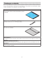
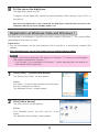
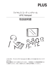
Wireless Meeting Tool UPIC Notepad User’s Manual We greatly appreciate your purchase of this PLUS UPIC Notepad. To be sure to make the most of this product’s functions, read this “User’s Manual” carefully before use. After reading, store the manual in a safe place for future reference. This is the manual for Notepad, the following wireless meeting tool, with which a digital pen, the main unit and the software are included. Product model name: UPIC Notepad (henceforth Notepad in this manual) When using the wireless interactive panel (sold separately) at the same time, please see the manual accompanying the panel. • When epexegesis and so on is included in an accompanying sheet, please ensure you see it. The software for this product is compatible with Windows 7 (32/64 bit), Windows Vista (32/64 bit) and Windows XP Service Pack3 or later (32 bit). It is not compatible with other OS. Trademarks • Microsoft and Windows are registered trademarks or trademarks in the United States and other countries of the Microsoft Corporation of the United States. • Adobe and Adobe Reader are trademarks of Adobe Systems Incorporated. • Anoto is a registered trademark of the Anoto Group AB. • Bluetooth and the Bluetooth logo are registered trademarks of Bluetooth SIG, Inc. Note that PLUS fully respects trademarks of corporations and products, even when not specially mentioned. Other product and company names in this manual are registered trademarks or trademarks of the respective corporations. (1) Reproduction of the contents of this manual, in full or in part, is prohibited. (2) The contents of this manual are subject to future change without notice. (3) The contents of this manual have been prepared with utmost care. If, however, you should notice any dubious points, errors or omissions or you should have any comments, please contact PLUS Corporation. (4) Please note that PLUS will accept no responsibility whatsoever for any damages, loss of earnings or other claims resulting from the use of this product, regardless of item (3) above. 2 Contents Important Safety Information…………………………………………………………… 4 Package contents………………………………………………………………………… 7 Names and functions of Notepad……………………………………………………… 8 Preparetion before use/how to quit ………………………………………………… 12 Installing the Software………………………………………………………………… 13 Before installing… …………………………………………………………………………… Operating environment… …………………………………………………………… Software provided… ………………………………………………………………… Updating UPIC Touch&Draw………………………………………………………… Installation of the provided software………………………………………………………… Uninstallation of the provided software… ………………………………………………… 13 13 13 13 14 16 Pairing the digital pen and computer… …………………………………………… 17 Mouse operation of the digital pen… ……………………………………………… 21 Registering on Windows XP… ……………………………………………………………… 17 Registration at Windows Vista and Windows 7… ………………………………………… 19 How to use the UPIC utility…………………………………………………………… 22 Display pop-up menu………………………………………………………………………… 22 Part Names and functions of the pop-up menu…………………………………………… 22 Using the VLP (Virtual Laser Pointer)… …………………………………………………… 26 Calibration of the PC screen and Notepad………………………………………… 27 Starting up and quitting UPIC Touch&Draw… …………………………………… 31 Starting up UPIC Touch&Draw……………………………………………………………… 31 Part names of UPIC Touch&Draw…………………………………………………………… 31 Quitting UPIC Touch&Draw… ……………………………………………………………… 34 Basic Operations of UPIC Touch&Draw… ………………………………………… 35 How to use the Office printing add-in… …………………………………………… 38 Troubleshooting………………………………………………………………………… 39 Specifications… ……………………………………………………………………… 40 Technical support… ………………………………………………………………………… 41 3 Important Safety Information Before using Symbols Explained Various symbols are used in this manual included with this product and on the product itself to ensure safe use of the product and to prevent injury to the user and others as well as damage to property. These symbols and their meanings are described below. Be sure to understand them fully before proceeding with your reading of the manual. • Regarding safety precautions of the projector (display device) , PC and Bluetooth USB adapter to be connected to the PC, please read the manual for each and ensure proper use of the same. Meaning of symbol Examples of symbol This symbol notifies of instructions urging caution (includCaution – risk of electric ing both danger and warnings). A more concrete indicator shock of the type of caution is shown inside the symbol. This symbol notifies of prohibited actions. A more concrete indicator of the type of prohibited action is shown Disassembly prohibited inside the symbol. This symbol notifies of actions that are restricted or Unplug the power cord instructions. A more concrete indicator of the instruction from the power outlet. is shown inside the symbol. CAUTIONS [Main body] Do not place magnetic recording media in the vicinity of the main unit. A magnet is embedded in this product. Please do not move magnetic recording media such as cash cards, commuter passes, floppy disks, video tapes, cassette tapes and so on in the vicinity of the main unit. Moving the latter closer than 10cm or so may result in damage to the recorded data. Please keep the fine parts such as the pen attached to this product out of reach of children. If swallowed, please consult a doctor immediately. Please do not use for medical appliances and precision measuring equipment affecting human life, equipment which could impact on important computer systems and equipment for which reliability is vital. Please do not use this product where the use of electronic devices is prohibited. 4 Do not touch the edge of the dot pattern sheet. Please be careful not to cut your hand on the edge of the dot pattern sheet. Do not use the included CD-ROM in a CD player for audio discs. Never use the included CD-ROM in a CD player for audio discs. Doing so will produce loud sounds which could injure your ears or damage your speakers. Additional Cautions Concerning use Please do not use in the following places. Doing so will cause distortions in the main unit and prevent it from achieving its original function. • Hot places exposed to direct sunlight • Places exposed to the direct wind from air-conditioners • Near heating appliances, heaters, etc. • Places exposed to soot or humidity (near kitchen counters, humidifiers, etc.) Do not scratch the dot pattern sheet Please do not strike or stick the sheet with sharp or hard things. Also, please do not bend the sheet. Doing so may result in read failure with the digital pen or malfunction. Do not wipe this product with chemicals Please do not wipe the main unit with thinner, benzene, alcohol and so on. Doing so may result in color change, damaging the main unit, then read failure with the digital pen or malfunction. [Others] Do not use a Bluetooth USB adapter on a USB hub. Operation is not guaranteed when a USB hub is used on the computer. Handling the CD-ROM Do not touch the surface with no label printed on it (the surface on which data is recorded). If the surface on which the data is recorded is dirty, the data cannot be read off the disc properly. Also, do not paste any paper, stickers, etc., onto the CD-ROM. Do not leave in places exposed to direct sunlight or near heating appliances for extended periods of time, and do not drop or bend. Doing so could warp the CD-ROM, making it impossible to read its data. 5 Cleaning Dots for coordinate detection are printed on the dot pattern sheet. If the surface of the sheet gets dirty, this may result in read failure during input with the digital pen or a malfunction. Please conduct the following regularly: Cleaning of the main unit - Please do not use moist tissue and OA cleaner. - Please lightly wipe the surface of the dot pattern sheet with a dry and soft cloth (cotton, cotton flannel and so on) . Wiping or rubbing strongly with a hard cloth will damage the surface of the sheet. - If badly stained, please gently wipe with a soft and lightly moistened cloth. Rubbing strongly will damage the surface of the sheet. LED RADIATION DO NOT VIEW DIRECTLY WITH OPTICAL INSTRUMENTS CLASS I LED PRODUCT Disposal of Waste Equipment by Users in Private Household in the European Union ( Applicable in the European Union and other European countries with collection systems ) This symbol on the product or on its packing indicates that this product should not be treated as household waste. Instead it should be delivered to the applicable collection point for the recycling of electrical and electronic equipment. By ensuring this product is disposed of correctly, you will help prevent potential negative consequences for the environment and human health, which could otherwise be caused by inappropriate waste handling of this product. The recycling of materials will help to conserve natural resources. For more detailed information about recycling of this product, please contact your local city office, your household waste disposal service or the shop where you purchased the product. Note: This symbol mark is for EU countries only. This symbol mark is according to the directive 2006/66/EC Article 20 Information for end-users and Annex II. This symbol means that batteries and accumulators, at their end-of-life, should be disposed of separately from your household waste. 6 Package contents If any of the following is missing in the packaging of the product you purchased, please contact the dealer, our company or the inquiry center. Name of package item Main body: 1 The dot pattern sheet on which the coordinate is printed is mounted. Digital pen (model ADP-301(type DP-301)): 1 set Including 1 spare stylus and 1 AAA alkaline battery Exclusive carrying case: 1 The main unit is portable. User’s Manual: 1 The directives to which we request you to adhere to ensure safe and main usage of this product are described. Digital pen operating instructions: 1 Directives to which we request you to adhere for safe usage, how to set dry-cell batteries and so on are recorded. CD-ROM: 1 A set of software is recorded. 7 Names and functions of Notepad Using the sheet on which the dot pattern coordinates are printed, draw with the digital pen, which also functions as a mouse and a virtual laser pointer. Command icon Command icon Base sheet Dot pattern sheet Digital pen Concerning the digital pen, please see the manual “ADP-301” 8 How to use the command icon Using the pre-prepared profile, users can register functions in the command icon. For each command icon, different functions can be registered for the two operations of “click” and “click and hold” respectively. Icons available for command registration Profile list 1 Touch&Draw Windows XP Vista/7 ○ ○ 2 User setting ○ ○ 3 Slide show ○ ○ 4 Windows Journal × ○ 5 Snipping Tool × ○ 6 Windows standard ○ ○ No. Profile name When activated Priority When Touch&Draw is running When the registered executable files are active When PowerPoint is running and active When Windows Journal is running and active When Snipping Tool is running and active When the profiles from 1 to 5 are not effective High *For details of the registered profiles, please see the help file. 9 Low Names and functions of the command icon The following explanations of the names and functions of the command icon are for when a click operation is carried out while only the Touch&Draw software is running. Command icons available for command registration can be changed at the setting menu of the UPIC utility / Register command Icon & Function Icons available for commnd registration Remarks (Only Touch&Draw is running) Start slide show ○ Touch&Draw Start-up ○ Starts up the Touch&Draw Direct Size Setting ○ Press down the Digital pen on the sheet to show the menu after selecting the icon, Slide the pen to select. Range select ○ The same function as Object Select of Touch&Draw Save ○ Same as Tool Bar of Touch&Draw Mouse ○ Same as Tool Bar of Touch&Draw Thin pen ○ Same as Tool Bar of Touch&Draw Felt Pen ○ Same as Tool Bar of Touch&Draw Thick underliner ○ Same as Tool Bar of Touch&Draw Eraser ○ Same as Tool Bar of Touch&Draw All Delete ○ The same function as Clear Handwriting of Touch&Draw Direct Color Setting ○ Press down the Digital pen on the sheet to show the menu after selecting the icon,Slide the pen to select. Virtual Laser Pointer × Executes virtual laser pointer Spotlight × Executes Spotlight of Virtual Laser Pointer Virtual Laser Pointer Setting × Displays the setting menu for the Virtual Laser Pointer Double-click × Executes a double-click of the mouse at the point next touched by the pen. Right-click × Executes a right-click of the mouse at the point next touched by the pen. 10 Page Up × Executes Page Up of the keyboard Page Down × Executes Page Down of the keyboard ESC (Escape) ○ Executes ESC (Escape) of the keyboard Enlarge × Executes scaling of the application screen. Roll × Rolls the displayed image on some application. Move × Executes move of the application screen. Launcher 1 ○ This key is not used (You can assign other key function to this key) Launcher 2 ○ This key is not used (You can assign other key function to this key) Launcher 3 ○ This key is not used (You can assign other key function to this key) Launcher 4 ○ This key is not used (You can assign other key function to this key) Launcher 5 ○ This key is not used (You can assign other key function to this key) Relative/ absolute Mode × Selects the Mouse Mode of Notepad Relative mode: Pointer moves in response to the direction and distance the pen is moved. Absolute mode: Pointer is set so that its motion on screen corresponds to that of the pen on Notepad UPIC Calibration × Executes Calibration of UPIC Paper Calibration × Displays the calibration menu of Notepad Settings × Displays the Setting Menu of the UPIC utility UPIC ○ Jumps to the product page of our website NOTICE • Command icons may not work properly in all the application software used. • For details, please see Help in the Touch&Draw. 11 Preparetion before use/how to quit When using the UPIC Notepad only NOTICE When using a computer on which steps 1 and 2 have been completed, start the preparations from step 3. 1 Install the software on the PC using the CD-ROM provided. 2 Make the computer recognize the digital pen (pairing). (See page 17.) (see page 15) * A commercially available Bluetooth USB adapter is required if the computer is not equipped with the Bluetooth function. * When using multiple digital pens, pair all the digital pens with the computer. 3 Calibrate the PC and Notepad (see page 27) 4 Set (check) the operation mode of the UPIC utility. Select “Use UPIC Notepad only” for [Mode] of the device setting. 5 Start up UPIC Touch&Draw. Now Notepad is ready for use. When using with output paper between Notepad, using a Microsoft Office add-in, please print out the PowerPoint materials after installing the provided software “Office Printing Add-in” (see page 38) After use 1. Close the software. (See page 34.) 2. Put the cap on the digital pen. The digital pen’s power turns off. 3. Place the UPIC Notepad in the dedicated carry case. 12 Installing the Software Before installing • Operating environment Item Operating system Internet Explorer Computer CPU Interface Memory Hard disk Display Peripherals Compatible Bluetooth stacks Description Windows 7 (32 bit / 64 bit), Windows Vista (32 bit / 64 bit), Windows XP (SP3 or later, 32-bit version) Ver. 6.0 or later Pre-installed computer on which one of the above operating systems is running 1GHz or greater processor Conforming to Bluetooth 2.0 Class 2 Windows 7:1 GB (32-bit)/2 GB (64-bit) or greater Windows Vista/Windows XP:512 MB or greater 200 MB or greater 1024 × 768 High Color or greater greater (recommended: color quality: Highest 32bit) Bluetooth adapter CD-ROM drive, standard USB port Microsoft Bluetooth stack Broadcom’s Widcomm Bluetooth software stack Toshiba Bluetooth stack BlueSoleil Bluetooth stack NOTE • Providing the above operating environment does not guarantee that all operations will work. • Not compatible with Macintosh. • When using a computer with no built-in Bluetooth function, a free port for connecting a Bluetooth USB adapter is required. • Software provided (As a part of UPIC Touch&Draw) This product is accompanied with the following software. For details, please see the software help. UPIC utility The digital pen allows the mouse operation of the PC and presentation with a virtual laser pointer. Also, calibration and assigning of functions to the command area of the UPIC Notepad sold separately is possible. UPIC Touch&Draw This is drawing software, which enables you to write characters by hand and insert images and figures onto the panel via the digital pen. It is used in combination with the UPIC utility. Office printing add-in It is used to print materials between dot pattern sheets at Microsoft Office add-in. Compatible Office versions: MS Office 2003/2007/2010 (only 32 bit) Compatible Office applications: PowerPoint • Updating UPIC Touch&Draw See the PLUS website. 13 Installation of the provided software “UPIC Utility” and “UPIC Touch&Draw” are installed when “Installation of Software” is selected from the included CD-ROM’s menu. When installing the Microsoft Office add-in, please select “Installation of Microsoft Office add-in” from the menus of the CD-ROM provided. • Check before installing 1.Check that the computer being used satisfies the required operating conditions. 2.When installing, do so with the authority (account) of the computer’s administrator. 3.Close any other running applications. • Installing UPIC Utility and UPIC Touch&Draw Cautions on installation • Depending on the parameters of the computer being used, a message asking you to confirm whether or not to allow execution of active contents may appear (ex: “Allow execution of active contents?”). If so, select [Yes] to proceed. NOTE: A security warning may appear. If so, select [Execute] and proceed to the next step. • When the included CD-ROM is first installed on a computer running on Microsoft Windows XP, the message below may appear: If so, be sure to select [Yes (Y)], and install “Microsoft .NET 2.0 Framework”. Some time is required for installation (about 10 minutes). If [No (N)] is selected, the programs may not be properly installed. 1 2 Insert the included CD-ROM into the computer’s CD-ROM drive. A menu screen appears automatically. If the screen does not appear automatically, open the CD-ROM folder and double-click “Autorun.exe”. Click “Installation of Software”. The installer is launched. Continued on next page 14 3 Follow the installer’s instructions to install the software. “UPIC Utility” and “UPIC Touch&Draw” are installed simultaneously. •When choosing “Mode” at installation, please specify the device you will use. •Normally, please select ”UPIC Notepad only”. This can be changed later. For details please see page 23. NOTICE • If using Windows Vista and Windows 7, the user account control dialog will be displayed. If Windows Vista, please select “Accept (A)”, if Windows 7, please select “Yes (Y) ”and continue installation. 4 Click [Finish]. The “Installer Information” dialogue box appears. Click [Yes (Y)] to restart the computer. This completes installation. Now proceed to the operation for pairing the digital pen and computer. (See page 20) NOTICE • Icon display of UPIC utility of Windows 7 When setting the icon of the UPIC utility to “Display in notification area”, the icon may be displayed. To display 1. Click the at the task bar, please proceed as follows: icon. The window will be displayed. 2. Drag the icon to the task bar. 15 Uninstallation of the provided software 1 2 3 4 Click [Start] → [Control Panel] to display the control panel window. • Check that the digital pen’s cap is attached and that its power is turned off. • Check that UPIC Touch&Draw is closed. Click “Uninstall Program”. * For Windows XP, the “Add/Remove Program” icon appears. The “Uninstall/Change Program” window appears. * For Windows XP, the “Add/Remove Program” icon appears. Select the items you want to delete from among the displayed list. * For Microsoft Office add-in, please uninstall the following items separately: Type of program Name UPIC software (UPIC utility UPIC PLUS UPIC Touch&Draw) Printing add-in PowerPoint 2003 PLUS UPIC Print Add in for PowerPoint 2003 Printing add-in PowerPoint 2007/2010 PLUS UPIC Print Add in for PowerPoint 2007/2010 5 6 For Windows Vista, click [Remove]*. For Windows XP, click [Remove]. Follow the instructions on the screen to proceed. NOTICE • If using Windows Vista and Windows 7, the user account control dialog will be displayed every time you run the uninstaller. If Windows Vista, please select “Accept (A) ”, if Windows 7, please select “Yes (Y) ”and continue installation. 16 Pairing the digital pen and computer The digital pen is a Bluetooth device. Signal transfer between it and the computer is not possible unless the computer has recognized the digital pen. This section describes pairing* using the Bluetooth stack included with Windows. * Pairing refers to the operation of connecting the digital pen and computer by wireless communication. In this manual pairing is also referred to as “connecting”. NOTE • Operation may be unstable when using multiple Bluetooth devices. • When using a computer with a built-in Bluetooth function, do not use a commercially available Bluetooth adapter. If you wish to use a Bluetooth adapter, turn off the built-in Bluetooth function. For instructions on how to do so, contact the manufacturer of your computer. • Multiple digital pens (Max.3 digital pens) can be connected simultaneously, but depending on the environment (computer/signal status, etc.), they may not operate. If the computer does not include a built-in Bluetooth device, use a commercially available Bluetooth USB adapter. Refer to the operating instructions of your Bluetooth USB adapter for instructions on pairing. Input “0000” as the digital pen’s path key. NOTICE Use a Bluetooth USB adapter supporting the HID (Human Interface Device) profile. Registering on Windows XP Preparations: 1.Turn on the Bluetooth function (the computer’s built-in function or a commercially available USB adapter). 2.Take the digital pen’s cap off. The power turns on and the indicator lights. 1 Click [Start] → [Control Panel] to open the control panel, then click [Printers and Other Hardware]. The “Printers and Other Hardware” window appears. 2 Click [Bluetooth Devices]. The “Bluetooth Devices” window appears. Continued on next page 17 3 4 Click [Add…]. The “Add Bluetooth Device Wizard” window appears. Check (click) the “My device is set up and ready to be found” checkbox, then click the [Next (N)] button. The next window in the add wizard appears. 5 Click “ADP-301B”, then click the [Next (N)] button. The next window in the add wizard appears. 6 Choose (click) the “Use the passkey found in the documentation (U)” radio button, input “0000” as the path key, then click the [Next (N)] button. The next window in the add wizard appears. 7 Click the [Finish] button. Continued on next page 18 8 Put the cap on the digital pen. The digital pen’s power turns off. To register multiple digital pens, repeat the above procedure. When doing so, input “0000” as the path key. Now when the digital pen’s cap is removed, the digital pen automatically connects to the computer and the pen input standby mode is set. Registration at Windows Vista and Windows 7 The following is an example of the Microsoft stack screen in Windows 7. The screen differs depending on the stack you use. Preparations: 1.Turn on the Bluetooth function (the computer’s built-in function or a commercially available USB adapter). 2.Take the digital pen’s cap off. The power turns on and the indicator lights. NOTE • When connecting the Bluetooth USB adapter to a Windows 7 PC, please use the Bluetooth USB adapter compatible for Windows 7. * If the software is not compatible with Windows 7, please download from the website of the Bluetooth USB manufacturer. 1 Click [Start] [Device and printer] The “Devices and Printers” window appears. If Vista Click [Start] → [Control Panel] to open the control panel, then click [Hardware and Sound]. The “Bluetooth Devices” window appears. 2 The “Add a device” window appears. Click [Add a device]. If Vista Click ”Bluetooth device” and click “Add (D) ” of the screen. The “Bluetooth device adding” screen appears. 19 3 Click “ADP-301B”, then click the [Next (N)] button. The next window in the add wizard appears. 4 Input “0000” as the pairing code, then click the [Next] button. The next window in the add wizard appears. 5 Click the [Close] button. 6 Put the cap on the digital pen to turn it off once. * To register multiple digital pens, repeat the above procedure. When doing so, input “0000” as the path key. Now when the digital pen’s cap is removed, the digital pen automatically connects to the computer and the pen input standby mode is set. 20 Mouse operation of the digital pen Moving the cursor Lift the digital pen slightly (Less than 5mm from the sheet surface) to move the cursor. Lift the pen slightly to move Click Touch the digital pen once. Touch once Double click Touch the digital pen twice continuously. Touch twice Right click Long-press the digital pen (until the right click menu appears) . Touch and hold 長くタッチ Drag Move the pen, touching the pen point of the digital pen. Drag 21 How to use the UPIC utility Display pop-up menu 1 Start up the UPIC utility Click the UPIC utility icon of the PC screen task tray to display the pop-up menu. If not displayed, click [Start][All programs][UPIC][UPIC utility] with the mouse, and it will appear (start up). If you use Windows 7 and the UPIC utility icon is not displayed in the task tray, please see the announcement of the “Icon display of UPIC utility of Windows 7” on page 18. *The remaining dry-cell battery level is displayed with the icon of the UPIC utility. • No battery power NOTICE When the switch of the digital pen is pressed while in use, it may result in a false trigger of the alarm signal indicating the remaining battery level. 2 Click your destination item. Choose your destination item among the menu to specify the setting change and operation. Part Names and functions of the pop-up menu Pointer The checkmark is indicated by clicking, and a Virtual Laser Pointer (VLP)* appears. To quit, display the pop-up menu again and remove the checkmark. * In the tub of the setting screen, the Virtual Laser Pointer is described as VLP for short. • When dragging, the pointer moves, and when touching-up, the pointer disappears. • To select the shape and type of the pointer, [Settings][VLP] tab [Pointer] 22 A checkmark is placed by clicking, and a spotlight appears. To quit, display the pop-up menu again and remove the checkmark. • When dragging, the position of the spotlight moves, and when touchingup, the spotlight disappears. • To select the shape, size and so on of the spotlight, [Settings][VLP] tab [Spotlight]. Spotlight Calibration/Cancel By clicking, the calibration patters appear. For the calibration method, please see page 28. Calibration at Startup By clicking, a checkmark is placed, and when detecting the connection of the digital pen, a calibration patter appears. (initial setting: ON) Settings Open the setting screen. By clicking the tabs of Device Settings, VLP and Register Command, it changes to your destination screen. If ”Use UPIC only” is selected at Device Settings, “Register Command” doesn’t appear. Device Settings screen Mode: You can select one of them. A checkmark is placed at the radio button by clicking . “Use UPIC only”……To select when using this product (M model or F model) only. “Use UPIC Notepad only”…To select when using the UPIC Notepad, which is only sold separately. “Use both”…… To select when using this product and the UPIC Notepad, which is sold separately, simultaneously. Select Monitor: Selecting the screen for the monitor number connected to the projector or the display is displayed. Search with an initial setting of “Display 1”. OK button: To close the setting menu and store the changes. Cancel button: To close the setting menu without storing the changes. Apply button: This is selectable when the setting contents are changed and intended to store the changes with the setting menu open. 23 VLP screen The VLP (Virtual Laser Pointer) includes the settings of the pointer and spotlight. Pointer settings Shape: To select the shape of the pointer Type: To select the type of the pointer Always on: Indicates the display settings for when the digital pen is away from the draw area. Place checkmark (On) …To display the pointer Take the checkmark off (Off) …Pointer disappears. (default setting) Spotlight settings Shape: To select the shape of the spotlight. (initial setting: round) Preview: This screen displays the status of your selection and settings. Adjustment is possible checking the width and height. Transparency:To adjust the transparency (the viewable area) around the spotlight. Register Command screen Profile Selects the profile to edit. .exe File Name Registers the application name to use. 24 Select Command Selects the command to register Command Settings Name : Click/Long Press : Registered Function : Keystroke : Link : Not Registered : Registers the command name Registers the command operation to register Sets the function registered to command Sets the keystroke in the command. Sets the execute file and URL address in the command. Unregisters a command Default Initializes the profile currently selected Help To display the help of the UPIC utility Exit To quit the UPIC utility. Once you have quit, the digital pen is no longer usable. 25 Using the VLP (Virtual Laser Pointer) Displaying a VLP (Virtual Laser Pointer) on the projection screen of a PC allows effective presentations to be made. A VLP includes a pointer and spotlight, with selectable shape and so on. (see page 27) 1 Example of the pointer Example of the spotlight Display the pop-up menu by clicking the icon of the UPIC utility and then clicking on [Pointer] or [Spotlight]. NOTE When using the spotlight, please check [Start][Control Panel][Screen][Settings] tab and change the screen color (C) to “highest (32bit)”. (When using Windows XP) to the point to which you want to 2 Drag point. The pointer moves by dragging. • The arrow cursor doesn’t follow. The pointer disappears at one point by touchingup. However, it will reappear by touching. • The figure on the right is an example of the pointer. 3 Quit the pointer display. Clicking or dragging outside the drawing area quits the pointer display. * In addition, operating procedure 1 while the pointer is displayed displays the pop-up menu and clicking [Pointer] or [Spotlight] quits the pointer display. 26 Calibration of the PC screen and Notepad Calibration involves adjusting the positions of the drawing area of the Notepad and the PC screen. There are three kinds of calibrations, namely “Fullscreen”, “Aspect Ratio” and “User”. NOTICE You cannot draw (operate) at the edge of the dot pattern sheet (3mm) . The dotted line indicates the limit of the read scope. Click the Calibration icon ( ) of the Notepad, display the Calibration menu on PC screen and select the type of calibration. Draw area Calibration icon Calibration menu 27 Fullscreen The scope of the PC screen and the draw area of Notepad are the same. UPIC Notepad Aspect Ratio Adjusts the PC screen to the draw area of Notepad, maintaining the aspect. UPIC Notepad Outside the draw area When the PC screen resolution is wide If “Fullscreen” is selected for calibration when the PC screen resolution is wide, the drawing is laterally stretched on the PC screen as in the following image: UPIC Notepad When the PC screen resolution is wide 28 User Adjusts the PC screen to the draw area of Notepad calibrated in “User Setting”. NOTICE • The digital pen automatically switches off when not used for about 7 minutes with the cap removed. • To use again cap the pen and uncap it to activate. Always cap the pen when at no use to avoid battery consumption. • Use 4:3 aspect ratio for UPIC Notepad. 1 2 3 Uncap the digital pen The indicator of the digital pen flickers. When lit up, no pairing (connection) with the PC is established. (see page 17) Slip the material for calibration in between the Notepad Please print out the material using the Office Printing add-in. (see page 38) In normal printing, the positional information may not be readable. C a l i b r a t e t h e re a d p o s i t i o n o f t h e Notepad and the PC screen Touch the Calibration icon ( ) of the Notepad to PIC U o N p te ad display the Calibration screen on the PC and select “User Setting”. Touch the marks of the paper slipped in between the Notepad in line with the calibration screen display. UPIC Notepad • Every time you touch, blinking moves in order of top left → bottom left → bottom right → top right. The calibration is now complete. • To cancel, please press the [Esc] key of the keyboard. You will return to the Calibration menu. UPIC Notepad 29 4 Select “User” from the Calibration menu. UPIC Notepad The area calibrated in “User Setting” now becomes the draw area. Draw area UPIC Notepad 30 Starting up and quitting UPIC Touch&Draw Starting up UPIC Touch&Draw 1 Start up UPIC Touch&Draw. There are three ways to start up this software. • The software can be started up by clicking [Start] → [All Programs] → [UPIC] → [UPIC Touch&Draw] on the computer. • UPIC Touch&Draw can be started up by doubleclicking the software’s icon on the Windows desktop. • UPIC Touch&Draw can be started up by double-clicking the file saved using the software’s “Save” command (extension .tad3). NOTICE • If connection to the digital pen is not possible, the message “Digital pen not detected. Application will terminate.” appears. Click [OK] to close the message. Once the digital pen is connected, start UPIC Touch&Draw back up. See “Pairing the digital pen and computer” on page 19. Part names of UPIC Touch&Draw After starting up, the tool bar will be displayed. For the detailed usage of the toolbar, and the selection and settings of each UPIC Touch&Draw function, please see the help of UPIC Touch&Draw. Tool bar in transverse configuration Configuration The direction of the toolbar switches between horizontal and vertical each time this is clicked. Move Drag here to move the menu to the desired position. 31 * Only one of the “Mouse”, “Pen”, “Felt Pen”, “Marker”, “Eraser”, “Figure” and “Select Object” icons can be selected at a time. It is not possible to select multiple icons. These seven functions are called input modes. Mouse Switches the input mode to the mouse mode. In this mode, the computer screen projected on the panel can be operated. • Some buttons does not function at mouse mode. • Windows operations can only be performed when in the mouse mode. • For mouse operation using a digital pen, please see page 21. Pen Switches the input mode to the pen mode. Set the pen thickness at “Style”, the pen color at “Color”. Felt Pen To change over the input mode to “Felt Pen”. The thickness of Felt Pen is set at “Size Setting” and its color is set via “Color Setting” Marker Switches the input mode to the marker mode. Set the marker thickness at “Style”, the marker color at “Color”. Eraser Switches the input mode to the eraser mode. • Use this to erase part of what you have written. Drag the eraser over words and lines you have drawn with the digital pen to erase that section. To delete in units of objects, use [Delete] at “Edit Object”. • Set the eraser thickness at “Style”. • Figures and images cannot be erased. Figure Displays the “Figure Menu” window. Click the desired figure icon and drag the digital pen to draw the figure. • Set the thickness of the lines at “Style”, the figure color at “Color”. • To close the “Figure Menu” window, either click the “Figure” icon on the toolbar. Select Object Switches the input mode to the object selection mode. To perform move, scaling, turn (figures only) and so on by choosing the object by clicking. Style Displays the “Style Menu” window. Use this to select the thickness of the tool for the currently selected input mode (pen, Felt Pen, marker, eraser or figure). Color Displays the “Color Menu” window. Use this to select the color for the currently selected input mode (pen, Felt Pen, marker or figure). Undo Up to the last 100 drawing or editing operations can be undone in order, starting from the most recently performed operation. Redo Restores the operations undone with the undo command, in order. Delete Displays the “Delete Menu” window. The screen turns off after the object is deleted. * To cancel, click somewhere outside the menu. The “Delete Menu” window turns off. CLEAR DRAWINGS: Clears letters or lines drawn with the digital pen. CLEAR ALL: Clears everything, including images inserted with the “Insert Picture” command. 32 Screen Mode The mode switches between “White Screen” and “Overlay Screen” each time the screen mode icon is clicked. When in the “Overlay Screen” mode : The computer’s screen is displayed on the background. Other applications can be displayed and written on with the digital pen. When in the “White Screen” mode : The background is a white screen with ruled lines. Insert Picture Displays the Windows “Open File” window. Images in JPEG, BMP, PNG, TIFF, GIF, WMF and UGM formats (dedicated material files) can be inserted. (see page 34) * If the image is larger than the drawing area, it is automatically reduced, keeping the same aspect ratio. Zoom Sets the magnification for the screen in the drawing area. Specify the area you want to enlarge by dragging. Right-click When [Right-click] is clicked, operation switches to the Windows mouse right-click operation. Open Displays the Windows “Open File” window. Use this to open files you have created and saved with UPIC Touch&Draw (.tad3 files). * Image files saved in formats other than TAD (.tad3) cannot be opened with this command. Save Displays the Windows “Save As” window. Use this to save the drawing area data. (See page 36.) The format for saving the data can be selected from one of the following: “.jpg” (JPEG format), “.bmp” (BMP format), “.png” (PNG format), “.tif” (TIFF format) or “.tad3” (TAD format) The file name is input automatically as follows: “[product name] + [date] + [serial number].xxx” (“xxx” being the extension for the selected file format). * .tad3 (TAD format) can be edited with this software by opening with [Open]. It is selectable only when the display mode is[White Screen. * If “.tad” is stored with this software, it will be changed to”.tad3”, and cannot be opened with older software versions. * Files saved with the extensions “.jpg”, “.bmp”, “.png” and “.tif” can be imported into other applications as image data. Print Opens the Windows “Print” window. Select the necessary items on the print window. See your Windows instructions. • When the screen mode is set to “Overlay Screen”, an image combining the Windows screen background with the drawing area data is printed. • When in the white screen mode, the drawing area data is printed. Help Displays the help menu. Minimize Closes the toolbar, placing the minimized icon in the task tray. Click this to display the toolbar as it was before it was minimized. Close UPIC Touch&Draw is closed, and the “Confirm closing” message is displayed. (See page 34.) 33 Quitting UPIC Touch&Draw 1 Click “Close” on the UPIC Touch&Draw window’s toolbar. When operating using the image projected on the panel, click “Close” on the toolbar. 2 UPIC Touch&Draw is closed, and the “Confirm closing” message is displayed. The message differs, depending on whether or not there is unsaved data. If there is no unsaved data: [Yes] Click this to quit UPIC Touch&Draw. [No] Click this to cancel quitting. If there is data that has not yet been stored: [Yes] When this is clicked, the Windows “Save as” window appears. UPIC Touch&Draw is closed after data storage is completed. [No] When this is clicked, UPIC Touch&Draw is closed without storing the data. [Cancel] Click this to cancel quitting. 3 Put the cap on the digital pen. 34 Basic Operations of UPIC Touch&Draw This section describes the basic operations in UPIC Touch&Draw. For details, please click the Help function of the toolbar. These basic operations are performed after calibration is completed and UPIC Touch&Draw has been started up. If UPIC Touch&Draw is not started up, see “Starting up and quitting UPIC Touch&Draw” on page 30. Example: Conducting a presentation in the overlay screen mode. The operations are performed on the picture projected on the wireless interactive panel. 1 Select the [Screen Mode] icon from the toolbar. The screen mode set when UPIC Touch&Draw is started up is the [Overlay Screen] mode. To use the white screen mode, click the [Screen Mode] icon and switch to the [White Screen] mode. 2 Operate Windows to display the presentation documents over the entire screen. Click the [Mouse] icon on the toolbar and open the desired presentation file. National Sales Figures 7000 6000 5000 4000 Amount 3000 Sales 2000 1000 0 Office A 3 Use the digital pen to write words and figures. Click the [Marker] icon on the toolbar and write with the digital pen. To change the marker color, click the [Color] icon and select the desired color. To change the thickness of the lines, click the [Style] icon and select the desired setting. 4 Inserting an image. Prepare the image beforehand. 1)Click the [Insert Picture] icon on the toolbar to display the “Open File” window. Continued on next page 35 Office C Office E Office G National Sales Figures 7000 6000 5000 4000 Amount 3000 Sales 2000 1000 0 Office A Office C Office E Office G 2)Select the desired file then click [Open]. The “Open File” window closes and the image is positioned at the center of the drawing area. 3)When the image is clicked after clicking the [Select Object] icon on the toolbar, a frame is displayed. Drag at any position within the frame to move the object to the desired position. National Sales Figures 7000 6000 5000 4000 Amount 3000 Sales 2000 1000 0 Office A 5 6 Drawing lines 1)Click the [Figure] icon on the toolbar , then on the “Figure Menu” window click the [Line] icon. 2)Now drag. A straight line is drawn with the position at which you started as the starting point. • To change the thickness of the line, select the desired thickness (in pixels) at [Style]. 3)To write freehand and draw letters, click the [Marker] icon on the toolbar and write with the digital pen. Store the data of the drawing area 1)Click the [Save] icon on the toolbar to display the “Save As” window. 2)Select “Save as type”, and select the file type. • The TAD format (“.tad3”) can only be selected when in the white screen mode. Files in this format can be opened with the “Open” command and edited with UPIC Touch&Draw. (TAD is a file format unique to UPIC Touch&Draw.) • When “.jpg”, “.bmp”, “.png” or “.tif” is selected, the image saved is a combination of the image in the drawing area and the Windows screen. Files in these formats can be loaded into other applications as image data. • The file name is input automatically as follows: “[product name] + [date] + [serial number].xxx” (“xxx” being the extension for the selected file format). We recommend changing the file names on the computer after quitting UPIC Touch&Draw to names that are more easily recognizable. 3)Click “Save”. 36 Office C Office E Office G National Sales Figures 7000 6000 5000 4000 Amount 3000 Sales 2000 1000 0 Office A Office C Office E Office G Office G 7 To conduct a new presentation at this point, first clear the drawing area. Click the [Delete] icon on the toolbar, then from the “Delete Menu” window click “CLEAR ALL” to delete all the data. * To cancel without deleting, click anywhere outside the “Delete Menu” window before clicking “CLEAR ALL”. National Sales Figures 7000 6000 5000 4000 Amount 3000 To continue, repeat operations 1 to 6. Sales 2000 1000 0 Office A 8 Ending the presentation See “Quitting UPIC Touch&Draw” on page 33. 37 Office C Office E Office G How to use the Office printing add-in If you install the ”Microsoft Office add-in” (printing add-in for PowerPoint) from the menu of the CD-ROM provided, you will be able to draw in the following program: • Microsoft PowerPoint 2003/2007/2010 (32 bit only) - If conducting printing from the Office printing add-in, it will be single color printing for Notepad. - Please use a color laser printer or color ink-jet printer. After installation, the Office printing add-in will be displayed in the menu bar of the program. 1 The “Print” screen appears. 2 Select the output printer and print. Click “Print” from the menu bar. Marks for calibration with Notepad will be printed on the paper. Marks for calibration NOTE Paper output in black-and-white print cannot be used. Doing so may result in read failure with the digital pen or malfunction. 38 Troubleshooting Digital pen problems Condition Digital pen’s indicator does not light/flash Digital pen’s indicator flashes (lit for 0.2 seconds, off for 3 second) Digital pen is not recognized (pairing is not possible) Digital pen has been recognized but pen does not write Writing is not possible with multiple digital pens simultaneously Mouse right-click operation does not function when the digital pen is pressed and held Check • Is a battery inserted in the digital pen? • Is the battery worn out? • Is the battery inserted in the wrong direction (+ and – polarities)? • Connection to device or pairing with the digital pen has not yet been completed. Pair the digital pen and computer. • Is the digital pen already paired with another computer? • Is the function turned off on the Bluetooth USB adapter or on the computer equipped with built-in Bluetooth function? • Is the battery worn out? • Has the digital pen been used at an angle exceeding 45 degrees relative to the verticality of the sheet surface? • Is any adhesive tape etc. attached to the sheet surface? • Is the stylus worn out? • When using multiple digital pens, it is not possible to draw with the pens simultaneously. Wait until the other person has finished before writing. • Is “Turn click lock on” selected (checked) at “Mouse properties” on the computer? * “Mouse properties” is located at [Start] → [Control Panel] → [Printers and Other Hardware]† → [Mouse]. † [Hardware and Sound] for Windows Vista. 39 Specifications Model name External dimensions Weight (Not including pen or accessories) Dot Pattern Sheet Size (mm) Read method Digital pen*2 *3 Model name*4 Power supply Interface Main unit weight Operating time Usage conditions Temperature Humidity Software provided UPIC Notepad (W)332mmx(D)8mmx(H)269mm *1 Approx. 445g 298W X 219H Anoto pattern read method by the read method of the Anoto pen*2*3 ADP-301 (Type name: DP-301) AAA alkali battery × 1 (1.5V) Conforming to Bluetooth 2.0 class 2*5 Approx. 40 g (0.1 lb) (including battery) During continuous drawing – Approx. 6 hours; In standby - Approx. 150 hours (with cap removed) 0°C to 40°C 30 to 85% (with no condensation) UPIC utility: Software for mouse operation and various functions (settings) UPIC Touch & Draw: Draw software Office printing add-in: Software to print out materials usable in Notepad*6 Included software operating environment Compatible operating systems Windows 7 (32 bit / 64 bit), Windows Vista (32 bit / 64 bit), Windows XP (SP3 or later, 32-bit version)*6 Compatible computer types Preinstalled models operating on one of the operating systems above 1GHz or greater processor CPU Memory Hard disk Display resolution Devices Compatible Bluetooth stacks Windows 7:1 GB (32-bit)/2 GB (64-bit) or greater, Windows Vista/Windows XP:512 MB or greater 200MB or greater 1024 × 768 pixels or greater, High Color or greater Bluetooth adapter*7, standard computer USB port, CD-ROM drive Microsoft Bluetooth stack Broadcom’s Widcomm Bluetooth software stack Toshiba Bluetooth stack BlueSoleil Bluetooth stack *1: Excluding projecting parts. *2: A computer and display device are required to draw with the digital pen. *3: For details on operating principles, etc., see http://www.anoto.com/ *4: Model subject to change without notice. *5: A separate Bluetooth adapter is required to connect to a computer not equipped with a built-in Bluetooth function. *6: Please use a PC which has Microsoft Office PowerPoint (from 2003) installed. *7: Providing the above operating environment does not guarantee that all operations will work. *8: No Bluetooth USB adapter is included. For a list of recommended commercially available Bluetooth USB adapters, see the Products page on our website. • Digital pens may be purchased separately as individual articles. For details, see our website. However, it is not possible to use multiple digital pens simultaneously. • The communication range of radio waves varies depending on the usage environment. It may narrow near devices potentially causing radio disturbance such as microwave ovens, cordless phones, wireless network devices and so on. 40 •Technical support If the problem with the product or software cannot be solved, contact your nearest PLUS Corporation office, dealer or store. Internet: http://www.plus-vision.com/en/support/index.html *PLUS only accepts inquiries made using the spaecial inquiry Form. Support We call support the provision of all kinds of information including answers to questions, requests, trouble reports, and other matters, and the scope of our support shall be limited to the functions and operation of this software. Problems that arise in using this software may be attributed to one of many causes, including the personal computer, the OS, other application software, and other peripheral devices. Accordingly, we only support problems that are attributable to this software. Also, this software is subject to version upgrades without prior notice due to the technical advancement of hardware and software. The customer can receive and use upgraded versions of this software through a method determined by us. Note that version upgrades will be limited to customers who consent to the aforementioned conditions of use. * Upon downloading this software from the PLUS Corporation Web site, or installing it from the CD-ROM, the customer is deemed to have consented to each of the terms. 41 © 2010, PLUS Corporation 24-4528-10A