1
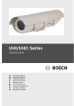
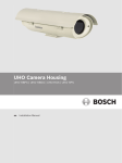
UHI/UHO Series
UHI-OG-0 | UHI-OGS-0 | UHO-HGS-10 | UHO-HBGS-10 | UHOHBPS-10 | UHO-HGS-50 | UHO-HBGS-50 | UHO-HPS-50 | UHOHBPS-50 | UHO-HBGS-60
en
User Manual
UHI/UHO Series | en
3
1
Unpacking
11
2
Service
11
3
Description
12
4
Installation
13
4.1
Tools required
13
4.2
Camera requirements
13
4.3
Cable requirements
14
4.3.1
Video transmission (coaxial)
14
4.3.2
Input power cord
14
4.3.3
Lens control cable
15
4.4
Housing mounting
15
4.5
Opening the cover
16
4.6
Camera/Lens installation
16
4.7
Camera/Lens wiring
18
4.7.1
Fittings
18
4.7.2
Conduit
19
4.7.3
Feed-through Wiring
19
4.7.4
Power Connections
20
4.8
Video coax connection
24
4.9
Lens wiring
25
4.10
Camera/Lens adjustment
25
4.11
Final assembly
25
4.12
Sunshield
26
4.13
Fuse replacement
26
5
UHO-HBPS-10, -50, and UHO-HPS-50
27
5.1
Camera/lens wiring
27
5.2
Video coax connection
28
Bosch Security Systems
User Manual
docnumber | V 2.0 | 2007.01
4
en |
UHI/UHO Series
6
Operation
28
7
Maintenance
28
8
Exploded view
29
docnumber | V 2.0 | 2007.01
User Manual
Bosch Security Systems
UHI/UHO Series | en
5
Important safety instructions
Read, follow, and retain for future reference all of the following safety
instructions. Heed all warnings on the unit and in the operating instructions
before operating the unit.
1.
Cleaning - Unplug the unit from the outlet before cleaning. Follow any
instructions provided with the unit. Generally, using a dry cloth for
cleaning is sufficient, but you can also use a moist fluff-free cloth or
leather shammy. Do not use liquid cleaners or aerosol cleaners.
2.
Heat Sources - Do not install the unit near any heat sources such as
radiators, heaters, stoves, or other equipment (including amplifiers)
that produce heat.
3.
Ventilation - Any openings in the unit enclosure are provided for ventilation to prevent overheating and ensure reliable operation. Do not block
or cover these openings. Do not place the unit in an enclosure unless
proper ventilation is provided, or the manufacturer's instructions have
been adhered to.
4.
Object and liquid entry - Never push objects of any kind into this unit
through openings as they may touch dangerous voltage points or shortout parts that could result in a fire or electrical shock. Never spill liquid
of any kind on the unit. Do not place objects filled with liquids, such as
vases or cups, on the unit.
5.
Lightning - For added protection during a lightning storm, or when leaving this unit unattended and unused for long periods, unplug the unit
from the wall outlet and disconnect the cable system. This will prevent
damage to the unit from lightning and power line surges.
6.
Overloading - Do not overload outlets and extension cords. This can
cause fire or electrical shock.
7.
Power cord and plug protection - Protect the plug and power cord from
foot traffic, being pinched by items placed upon or against them at
electrical outlets, and its exit from the unit. For units intended to operate with 230 VAC, 50 Hz, the input and output power cord must comply
with the latest versions of IEC Publication 227 or IEC Publication 245.
8.
Power disconnect - Units with or without ON/OFF switches have power
supplied to the unit whenever the power cord is inserted into the
power source; however, the unit is operational only when the ON/OFF
switch is in the ON position. The power cord is the main power disconnect device for switching off the voltage for all units.
9.
Power sources - Operate the unit only from the type of power source
indicated on the label. Before proceeding, be sure to disconnect the
power from the cable to be installed into the unit.
–
For battery powered units, refer to the operating instructions.
Bosch Security Systems
User Manual
docnumber | V 2.0 | 2007.01
6
en |
UHI/UHO Series
–
For external power supplied units, use only the recommended or approved power supplies.
–
For limited power source units, this power source must
comply with EN60950. Substitutions may damage the unit
or cause fire or shock.
–
For 24 VAC units, voltage applied to the unit's power input
should not exceed 25.4 VAC. User-supplied wiring must
comply with local electrical codes (Class 2 power levels).
Do not ground the supply at the terminals or at the unit's
power supply terminals.
–
If unsure of the type of power supply to use, contact your
dealer or local power company.
10. Servicing - Do not attempt to service this unit yourself. Opening or
removing covers may expose you to dangerous voltage or other hazards. Refer all servicing to qualified service personnel.
11. Damage requiring service - Unplug the unit from the main AC power
source and refer servicing to qualified service personnel when any damage to the equipment has occurred, such as:
–
the power supply cord or plug is damaged;
–
exposure to moisture, water, and/or inclement weather
(rain, snow, etc.);
–
liquid has been spilled in or on the equipment;
–
an object has fallen into the unit;
–
unit has been dropped or the unit cabinet is damaged;
–
unit exhibits a distinct change in performance;
–
unit does not operate normally when the user correctly follows the operating instructions.
12. Replacement parts - Be sure the service technician uses replacement
parts specified by the manufacturer, or that have the same characteristics as the original parts. Unauthorized substitutions may cause fire,
electrical shock, or other hazards.
13. Safety check - Safety checks should be performed upon completion of
service or repairs to the unit to ensure proper operating condition.
14. Installation - This installation should be made by a qualified service person in accordance with the manufacturer's instructions and in accordance with applicable local codes.
15. Attachments, changes or modifications - Only use attachments/accessories specified by the manufacturer. Any change or modification not
expressly approved by Bosch of the equipment or authorization agreement could void the user's guarantee or authority to operate the equipment.
docnumber | V 2.0 | 2007.01
User Manual
Bosch Security Systems
UHI/UHO Series | en
7
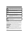
DANGER! High risk:
This symbol indicates an imminently hazardous situation such
as "Dangerous Voltage" inside the product. If not avoided, this
will result in an electrical shock, serious bodily injury, or death.
!
!
WARNING! Medium risk:
Indicates a potentially hazardous situation.
If not avoided, this could result in serious bodily injury or death.
WARNING! Medium risk:
Indicates a potentially hazardous situation. If not avoided, this
may result in minor or moderate injury. Alerts the user to
important instructions accompanying the unit.
CAUTION!
Indicates a potentially hazardous situation.
If not avoided, this may result in property damage or risk of
damage to the unit.
i
NOTICE!
This symbol indicates information or a company policy that
relates directly or indirectly to the safety of personnel or
protection of property.
Accessories - Do not place this unit on an unstable stand, tripod, bracket, or
mount. The unit may fall, causing serious injury and/or serious damage to
the unit. Use only with the cart, stand, tripod, bracket, or table specified by
the manufacturer. When a cart is used, use caution and care when moving
the cart/apparatus combination to avoid injury from tip-over. Quick stops,
excessive force, or uneven surfaces may cause the cart/unit combination to
overturn. Mount the unit per the manufacturer's instructions.
All-pole power switch - Incorporate an all-pole power switch, with a contact
separation of at least 3 mm in each pole, into the electrical installation of
the building to disconnect the unit by switching off the voltage to the unit.
Camera grounding - For mounting the camera in potentially damp environments, ensure to ground the system using the ground connection of the
power supply connector. See Section 4.7.4 Power Connections.
Camera lens - An assembled camera lens in the outdoor housing must comply and be tested in accordance with UL/IEC60950. Any output or signal
lines from the camera must be SELV or Limited Power Source. For safety
reasons the environmental specification of the camera lens assembly must
be within the environmental specification of -10 °C (+14 °F) to +50 °C
(+122 °F).
Bosch Security Systems
User Manual
docnumber | V 2.0 | 2007.01
8
en |
UHI/UHO Series
Camera signal - Protect the cable with a primary protector if the camera signal is beyond 140 feet, in accordance with NEC 800 (CEC Section 60).
Coax grounding
–
Ground the cable system if connecting an outside cable
system to the unit.
–
Connect outdoor equipment to the unit's inputs only after
this unit has had its grounding plug connected to a
grounded outlet or its ground terminal is properly connected to a ground source.
–
Disconnect the unit's input connectors from outdoor
equipment before disconnecting the grounding plug or
grounding terminal.
–
Follow proper safety precautions such as grounding for
any outdoor device connected to this unit.
U.S.A. models only - Section 810 of the National Electrical Code, ANSI/NFPA
No.70, provides information regarding proper grounding of the mount and
supporting structure, grounding of the coax to a discharge unit, size of
grounding conductors, location of discharge unit, connection to grounding
electrodes, and requirements for the grounding electrode.
Disposal - Your Bosch product was developed and manufactured with high-quality material and components that can be
recycled and reused. This symbol means that electronic and
electrical appliances, which have reached the end of their working life, must be collected and disposed of separately from
household waste material. Separate collecting systems are usually in place for disused electronic and electrical products.
Please dispose of these units at an environmentally compatible
recycling facility, per European Directive 2002/96/EC.
Environmental statement - Bosch has a strong commitment towards the
environment. This unit has been designed to respect the environment as
much as possible.
Electrostatic-sensitive device - Use proper CMOS/MOS-FET handling precautions to avoid electrostatic discharge. NOTE: Wear required grounded wrist
straps and observe proper ESD safety precautions when handling the electrostatic-sensitive printed circuit boards.
Outdoor signals - The installation for outdoor signals, especially regarding
clearance from power and lightning conductors and transient protection,
must be in accordance with NEC725 and NEC800 (CEC Rule 16-224 and CEC
Section 60).
Permanently connected equipment - Incorporate a readily accessible disconnect device in the building installation wiring.
Pluggable equipment - Install the socket outlet near the equipment so it is
easily accessible.
docnumber | V 2.0 | 2007.01
User Manual
Bosch Security Systems
UHI/UHO Series | en
9
Power lines - Do not locate the camera near overhead power lines, power
circuits, or electrical lights, nor where it may contact such power lines, circuits, or lights.
Video loss - Video loss is inherent to digital video recording; therefore,
Bosch Security Systems cannot be held liable for any damage that results
from missing video information. To minimize the risk of lost digital information, Bosch Security Systems recommends multiple, redundant recording
systems, and a procedure to back up all analog and digital information.
Warning - This device is intended for use in public areas only. U.S. federal
law strictly prohibits surreptitious recording of oral communications.
FCC & ICES Information
(U.S.A. and Canadian Models Only)
This equipment has been tested and found to comply with the limits for a
Class B digital device, pursuant to part 15 of the FCC Rules. These limits are
designed to provide reasonable protection against harmful interference in a
residential installation. This equipment generates, uses, and can radiate
radio frequency energy and, if not installed and used in accordance with the
instructions, may cause harmful interference to radio communications. However, there is no guarantee that interference will not occur in a particular
installation. If this equipment does cause harmful interference to radio or
television reception, which can be determined by turning the equipment off
and on, the user is encouraged to try to correct the interference by one or
more of the following measures:
–
reorient or relocate the receiving antenna;
–
increase the separation between the equipment and
receiver;
–
connect the equipment into an outlet on a circuit different
from that to which the receiver is connected;
–
consult the dealer or an experienced radio/TV technician
for help.
Disclaimer
Underwriter Laboratories Inc. ("UL") has not tested the performance or reliability of the security or signaling aspects of this product. UL has only tested
fire, shock and/or casualty hazards as outlined in UL's Standard(s) for Safety
for Closed Circuit Television Equipment, UL 2044. UL Certification does not
cover the performance or reliability of the security or signaling aspects of
this product.
UL MAKES NO REPRESENTATIONS, WARRANTIES, OR CERTIFICATIONS
WHATSOEVER REGARDING THE PERFORMANCE OR RELIABILITY OF ANY
SECURITY OR SIGNALING RELATED FUNCTIONS OF THIS PRODUCT.
Bosch Security Systems
User Manual
docnumber | V 2.0 | 2007.01
10 en |
docnumber | V 2.0 | 2007.01
UHI/UHO Series
User Manual
Bosch Security Systems
UHI/UHO Series Unpacking | en
1
11
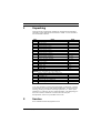
Unpacking
This electronic equipment should be unpacked and handled
carefully. Verify that the items listed in Table 1.1 are included
for the model ordered.
Qty.
Item
Part
1
Housing (with correct model number)
ABS
1
Spacer, 4 mm
ABS
1
Spacer, 9 mm
ABS
2
Screw, 1/4-20 x 1/4 in
SS
2
Screw, 1/4-20 x 3/8 in
SS
2
Screw, 1/4-20 x 3/4 in
SS
2
Screw, 1/4-20 x 5/8 in
SS
2
Screw, 1/4-20 x 7/16 in
SS
2
Screw, 1/4-20 x 1/2 in
SS
3
Screw, tamper-resistant
M3.5 T15
1
Wrench, tamper-resistant
M3.5 T15
1
Camera tray, part A
PS
1
Camera clamp
SS
2
Large washer, flat (camera to tray)
SS
3
Washer, flat
M6 SS
3
Washer, lock
M6 SS
3
Washer, flat
M6 SS
Models: UHI-OG-0, UHI-OGS-0, UHO-HGS-10, UHO-HBGS-10,
UHO-HGS-50, UHO-HBGS-50, UHO-HBGS-60
2
Fittings, 3/8-inch NPT with locking nut
2
Fittings, 1/2-inch NPT with locking nut
Models: UHO-HBPS-10
1
4-pin mating connector
Male
Models: UHO-HPS-50, UHO-HBPS-50
1
4-pin mating connector
Female
Table 1.1 Parts list
If an item appears to have been damaged in shipment, replace
it properly in its carton and notify the shipper. If any items are
missing, notify your Bosch Security Systems, Inc. sales representative or customer service representative. The shipping carton is the safest container in which the unit may be
transported. Save it for possible future use.
2
Service
See: www.boschsecuritysystems.com
Bosch Security Systems
User Manual
F.01U.026937 | V 2.0 | 2007.01
12 en | Description
3
UHI/UHO Series
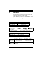
Description
The UHI/UHO series are attractively styled housings for indoor
and outdoor use. These housings meet customer demand for
appearance, cost competitiveness, and easy installation. See
Table 3.1 for a description of indoor models.
Heaters and blowers for all models operate at 50/60Hz. The 4pin models have a 4-pin connector and a BNC connector
instead of feed-through fittings.
Key to installed accessory:
Htr = heater; Blr = blower; SS = sun shield
UHI-OG-O
UHI-OGS-O
NA
NA
24/120/230 VAC
91 x 81 x 262 mm (3.6 x 3.2 x 10.3 in)
Installed accessory
Voltage range / power
Camera voltage ratings
Max camera/lens size (HWD)
Table 3.1 Indoor units
Installed accessory
Voltage range / power
Camera ratings
Max camera/lens size (HWD)
UHO-HGS-10
Htr, SS
UHO-HBGS-10
UHO-HBPS-10
Htr, Blr, SS
Htr, Blr, SS, 4-pin
21.6 to 25.4 VAC / 40 W
24 VAC
91 x 81 x 262 mm (3.6 x 3.2 x 10.3 in)
Table 3.2 Outdoor 24 volt units
Installed accessory
Voltage range / power
Camera voltage ratings
Max camera/lens size (HWD)
UHO-HBGS-60
Htr, Blr, SS
108 to 132 VAC / 45 W
120 V
91 x 81 x 262 mm (3.6 x 3.2 x 10.3 in)
Table 3.3 Outdoor 120 volt unit
UHO-HGS-50
UHO-HPS-50
UHO-HBGS-50
UHO-HBPS-50
Installed acces- Htr, SS
Htr, SS, 4-pin
Htr, Blr, SS
Htr, Blr, SS, 4-pin
sory
Voltage range /
198 to 254 VAC / 40 W
198 to 254 VAC / 45 W
power
Camera ratings
230 VAC
Max camera/lens
91 x 81 x 262 mm (3.6 x 3.2 x 10.3 in)
size (HWD)
Table 3.4 Outdoor 230 volt units
F.01U.026937 | V 2.0 | 2007.01
User Manual
Bosch Security Systems
UHI/UHO Series Installation | en
4
4.1
4.2
13
Installation
!
CAUTION!
Installation should only be performed by qualified service
personnel in accordance with the National Electrical Code or
applicable local codes.
!
CAUTION! These units must be properly and securely mounted to a
supporting structure capable of sustaining the unit weight. Use care
when selecting mounts or pan/tilts (not supplied) for installation; the
mounting surface and unit's weight should be carefully considered.
Tools required
–
Small flat blade screwdriver
–
Phillips screwdriver (#1)
–
Adjustable wrench
–
Wire cutter/stripper/crimper tool
Camera requirements
The cameras to be built into the housing must meet the requirements specified in Table 4.1.
Ambient temperature
Power consumption
Voltage for low voltage units
Voltage for high voltage units
Weight without lens
Weight with lens
Temperature under operating
conditions
0 °C to +50 °C (+32 °F to +122 °F)
10 W (max)
12 VAC to 28 VAC; +12 VDC to +30 VDC
100 VAC to 240 VAC
450 g max
1 kg max
-20 °C to +50 °C (-4 °F to +122 °F)
Table 4.1 Specifications for cameras
Bosch Security Systems
User Manual
F.01U.026937 | V 2.0 | 2007.01
14 en | Installation
UHI/UHO Series
4.3
Cable requirements
4.3.1
Video transmission (coaxial)
Cable type
runs < 300m (1000 ft)
runs < 600m (2000 ft)
Cable diameter (outer)
Cable shape
Cable shield
Center conductor
DC resistance
RG-59/U
RG-11/U
Cable impedance
Certificating authority
Environmental
Temperature rating
Reference type
RG-59/U
RG-11/U
4.6 mm to 7.9 mm
(0.18 in to 0.31 in)
Round
>93% braided copper
Stranded or solid copper
<15 ohm/1000 m
<6 ohm/1000 m
75 ohm
UL
Outdoor rated
+80 °C (+176 °F) or greater
Belden 9259
Table 4.2 Video cable specifications
4.3.2
Input power cord
Cable type
Cable diameter (outer)
3 x 18 AWG
4.6 to 7.9 mm
(0.18 to 0.31 in)
Round
3 or 2
300 V
UL/C.S.A., UL VW-1
Outdoor rated
+105° C (+221° F) or greater
Belden 19509, 3-conductor;
Northwire FSJT183-81K, 3-conductor
Cable shape
Conductors
Voltage rating
Certificating authority
Environmental
Temperature rating
Reference type
Table 4.3 Power cord specifications for North America
F.01U.026937 | V 2.0 | 2007.01
User Manual
Bosch Security Systems
UHI/UHO Series Installation | en
15
Cable type
H05RN-F 3 G 0.75;
H05RN-F 3 G 1.00
4.6 to 7.9 mm
(0.18 to 0.31 in)
Round
3 or 2
300 V
VDE
Outdoor rated
Olflex rubber cable 1600 252;
Olflex rubber cable 1600 253
Cable diameter (outer)
Cable shape
Conductors
Voltage rating
Certificating authority
Environmental
Reference type
Table 4.4 Power cord specifications for Europe
4.3.3
Lens control cable
Cable type
Cable diameter (outer)
Jacketed multiconductor cable
4.6 to 7.9 mm
(0.18 to 0.31 in)
Round
Overall
4 and 8
Stranded 20 to 16 AWG
Color coded
Cable shape
Cable shield
Conductors
Conductor type
Conductor insulation
Table 4.5 Lens control cable specifications
4.4
Housing mounting
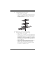
1.
Use two 1/4-20 x 0.50 in screws and 1/4 in spring washers
to mount the housing to a mount or a pan/tilt. The spring
washers must be used for the screws to thread properly.
2.
The outermost set of 1/4-20 threaded holes are for mounting to feed-through mounts, and the innermost 1/4-20
holes are for mounting to all other mounts and pan/tilts.
See Figure 4.1.
Bosch Security Systems
User Manual
F.01U.026937 | V 2.0 | 2007.01
16 en | Installation
UHI/UHO Series
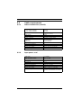
For mounting with rear connections
For mounting with feed-through wiring
Fig. 4.1 Thread holes for mounting with rear connections, or for feed
through wiring
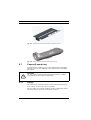
4.5
Opening the cover
!
WARNING!
The heater will be HOT when in operation - DO NOT TOUCH.
Always switch heater OFF when working on the camera.
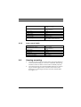
Open the cover by unlatching the three latches on the side of
the housing. See Figure 4.2. If the optional tamper-resistant
screws have been installed, use the supplied wrench to remove
the screws before opening the latches.
Latches
Fig. 4.2 Unlatching the cover
4.6
Camera/Lens installation
1.
Remove the two screws holding the camera tray to the
housing. Remove tray from the housing.
2.
If using the feed-through feature, refer to
Section 4.7.3 Feed-through Wiring.
F.01U.026937 | V 2.0 | 2007.01
User Manual
Bosch Security Systems
UHI/UHO Series Installation | en
3.
17
For installation of zoom lens cameras:
a.
Attach the lens to the camera.
b.
Use the various 1/4-20 screws and appropriate 4 mm
and/or 9 mm spacers provided to mount the camera
and the lens to the camera tray. This camera tray is
already pre-installed.
Fig. 4.3 Spacers for mounting zoom lens and camera
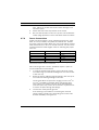
4.
Mounting fixed lens cameras in all housings:
c.
Attach the lens to the camera.
d.
Combine the 4 mm and the 9 mm spacers provided to
mount the camera to the optional camera tray type A
(use different combinations of the spacers to ensure
that the camera lens is in the middle of the window).
Use the 1/4-20 x 5/8 in screw and large flat washer to
secure the camera and spacer to the camera tray, as
shown in Figure 4.3.
e.
Slide the camera/lens tray in under the slot near the
hinge side of the housing, as shown in Figure 4.5.
Slide the entire assembly forward approximately
5 mm (0.2 in) from the front of the window. Install
screws into the appropriate holes.
Bosch Security Systems
User Manual
F.01U.026937 | V 2.0 | 2007.01
18 en | Installation
UHI/UHO Series
Fig. 4.4 Optional camera tray type A for fixed lens camera
Fig. 4.5 Sliding camera/lens tray assembly into slot
4.7
Camera/Lens wiring
See Section 3.2 Outdoor 24 volt units and Section 3.4 Outdoor
230 volt units for UHO-HBPS-10, UHO-HPS-50 and UHO-HBPS50 models.
!
4.7.1
CAUTION!
Use only cables meeting specifications in Section 4.3 Cable
requirements,to wire cameras and lenses.
Fittings
The 3/8-inch NPT fitting accepts a round cable with diameter
from 4.0 mm (0.16 in) to 7.0 mm (0.28 in).
The two larger 1/2-inch NPT fittings accept cables with diameters from 6.5 mm (0.26 in) to 10.5 mm (0.42 in).
F.01U.026937 | V 2.0 | 2007.01
User Manual
Bosch Security Systems
UHI/UHO Series Installation | en
!
4.7.2
19
CAUTION! Always securely tighten all fittings to ensure a liquidtight seal. Failure to do so could allow water to enter the
housing and damage the camera and lens. If a sealant is used,
be sure it is a neutral cure type. Sealants that release acetic
acid may harm camera electronics. Use of drip loops is
recommended on the wiring outside of the rear end cap.
Conduit
These housings allow direct connection of conduit.
4.7.3
1.
Remove the rear hole plugs and attach the conduit and
conduit fittings directly to the housing rear cap. The holes
accept either 3/8-inch NPT or 1/2-inch NPT conduit fittings.
2.
Any unused holes must be covered using the plugs provided with the housing.
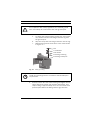
Feed-through Wiring
Use feed-through mounts to feed cabling through the foot of
the housing.
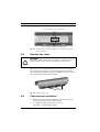
1.
Prior to mounting the camera, remove the two dome plugs
located inside the housing See Figure 4.6.
Holes
Fig. 4.6 Location of feed through wiring holes.
2.
Screw the two 3/8-inch NPT fittings into the foot of the
housing.
3.
Pull the cabling through the fittings into the housing.
Tighten the fitting to 4.0 Nm to 4.5 Nm (35 inch-lb to
40 inch-lb). This torque rating is approximately 1 to 1.5
turns past the point where the fitting starts to grip the
Bosch Security Systems
User Manual
F.01U.026937 | V 2.0 | 2007.01
20 en | Installation
UHI/UHO Series
wire. Failure to do this will result in water damage to all
electronic parts.
4.7.4
4.
Attach the foot to the top bracket of the mount.
5.
Be sure that the holes in the rear cap are covered with the
rubber plugs provided. Push in until flush and then release.
Power Connections
Power into the housings is to be supplied using type UL Standard SJ cord (or better) acceptable for outdoor use. Installation must conform to NEC 400-4 CEC rule 4-010 and be marked
with OUTDOOR, W, or W-A. For 24-volt cameras, use the recommended maximum cable lengths chart for selecting the proper
wire size.
Wire size mm2
Wire size AWG
Distance m (ft)
0.5
1
1.5
2.5
4
20
18
16
14
12
27 (90)
42 (140)
67 (220)
108 (355)
172 (565)
Table 4.6 Recommended maximum cable lengths for housings equipped
with 24-volt cameras, heaters, and blowers
Wire sizes larger than 2.5 mm2 (14 AWG) require a splice to
accommodate the terminal block.
1.
If using the feed-through option, ignore this step. Install
one of the large 1/2-inch NPT fittings into one of the holes
in the rear cap.
2.
Route the power cable through the fitting in the rear cap or
one of the feed-through fittings in the foot.
The terminal block accepts wire ranging from 0.5 mm2 to
2.5 mm2 (20 AWG to 14 AWG). When using larger wire
sizes, splice to a smaller size wire at the terminal block
end. The splice may need to be enclosed in a junction box
if it does not pass through the fittings.
3.
Connect the safety (earth) ground:
A terminal lug is provided for connecting the external
safety (earth) ground to the grounding post on the PCB
bracket assembly. See Figure 4.7.
F.01U.026937 | V 2.0 | 2007.01
User Manual
Bosch Security Systems
UHI/UHO Series Installation | en
!
21
CAUTION!
For compliance with safety regulations, the external ground
wire must always be connected to the main ground post.
a.
To attach the external safety ground wire, remove the
nut, washers and the external ground wire lug from
the ground post.
b.
Strip and crimp the external ground wire into the lug.
c.
Reattach the ground connections in the order shown
in Figure 4.7.
Nut
Lock washer
Flat washer
External ground lug
External ground post
Fig. 4.7 Safety grounding
i
NOTE!
Install the external ground in accordance with the NEC/CEC
requirements.
4.
Pull any excess wire out of the housing and tighten the fitting to 8.5 Nm to 9.0 Nm (75 inch-lb to 80 inch-lb). This
torque rating is approximately one to one and a half turns
past the point where the fitting starts to grip the wire.
Bosch Security Systems
User Manual
F.01U.026937 | V 2.0 | 2007.01
22 en | Installation
!
UHI/UHO Series
CAUTION!
Be sure to securely tighten all fittings to ensure a liquid-tight
seal. Failure to do this could allow water to enter the housing
and damage electronic parts, camera, and lens.
5.
Connect the supply power wires to the terminal block. See
Figure 4.8. Strip no less than 6 mm (0.25 in) and no more
than 8mm (0.31 in) of insulation away from the wire. Be
sure not to nick the wires.
6.
Cut the power cord on 120 VAC and 230 VAC camera models; leave enough cable to allow connection to the terminal
block. Strip no less than 6 mm (0.25 in) and no more than
8 mm (0.31 in) of insulation away from the wire. Be sure
not to nick the wires. Connect these wires to the connectors provided on the terminal block. See Figure 4.8.
F.01U.026937 | V 2.0 | 2007.01
User Manual
Bosch Security Systems
UHI/UHO Series Installation | en
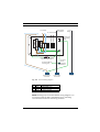
23
To camera
To accessories
BNC cable
to camera
Power input
grounding
post
L
FUSE
N
G
N
G
x
N
L
L
Lens
wiring
1
2
Ground test connector
Do NOT disconnect
Ground
stud
housing
bottom
Ground cable to
housing top
L
N
G
Power input
connector
Video input
connector
Lens
Fig. 4.8 Terminal wiring diagram
Pin
N
L
G
Color
Blue
Brown
Green
Connection
Power connection
Power connection
G (safety ground)
Table 4.7
NOTE! Drawing layout and installation wiring diagram is in
accordance with the NEC, ANSI/NFPA 70 for indicating
recommended locations and wiring methods.
Bosch Security Systems
User Manual
F.01U.026937 | V 2.0 | 2007.01
24 en | Installation
!
4.8
UHI/UHO Series
CAUTION!
For security protection of the device, the branch circuit
protection must be secured with a maximum fuse rating of 16A.
This must be in accordance with NEC 800 (CEC Section 60).
7.
On heater and heater/blower units, make sure the heater
and fan wires stay connected to the terminal block.
8.
Make sure the BNC cable is separated from the Mains
power and heater.
Video coax connection
See Table 3.2 and Table 3.4 for UHO-HBPS-10, UHO-HPS-50 and
UHO-HBPS-50 models.
1.
!
!
Install a 1/2-inch NPT fitting into the available hole in the
rear cap.
CAUTION!
Use only cables meeting specifications in Section 4.3 Cable
requirements for wiring video coax connections.
2.
Route the video coax cable through one of the fittings
installed in Step 1., or one of the feed-through fittings in
the base.
3.
Attach the BNC connector to the coax and connect it to the
camera.
CAUTION! Always securely tighten all fittings to ensure a liquidtight seal. Failure to do so could allow water to enter the
housing and damage the camera and lens. If a sealant is used,
be sure it is a neutral cure type. Sealants that release acetic
acid may harm camera electronics. Use of drip loops is
recommended on the wiring outside of the rear end cap.
4.
Pull any excess wire out of the housing and tighten the fitting to 8.5 Nm to 9.0 Nm (75 inch-lb to 80 inch-lb). This
torque rating is approximately one to one and a half turns
past the point where the fitting starts to grip the wire.
F.01U.026937 | V 2.0 | 2007.01
User Manual
Bosch Security Systems
UHI/UHO Series Installation | en
4.9
25
Lens wiring
1.
!
CAUTION!
Use only cables meeting specifications in Section 4.3 Cable
requirements, for wiring cameras and lenses.
2.
!
Install the 3/8-inch NPT fitting into the middle hole in the
rear cap.
If installing a zoom lens, insert the lens control cable
through the last fitting at the rear of the housing. Attach
the lens wiring to the lens mating connector and connect it
to the lens. If a mating connector is not available, connect
directly to the lens cable.
CAUTION! Always securely tighten all fittings to ensure a liquidtight seal. Failure to do so could allow water to enter the
housing and damage the camera and lens. If a sealant is used,
be sure it is a neutral cure type. Sealants that release acetic
acid may harm camera electronics. Use of drip loops is
recommended on the wiring outside of the rear end cap.
3.
Pull any excess wire out of the housing and tighten the fitting to 8.5 N m to 9.0 N m (75 in-lb to 80 in-lb). This torque
rating is approximately 1 to 1-1/2 turns past the point
where the fitting starts to grip the wire.
4.
If using a pan/tilt with a feed-through cable, insert the
camera/lens function cable through the left fitting at the
rear of the housing. Wire the required functions.
For correct plug connection, see specification on lens cord.
4.10
Camera/Lens adjustment
Verify operation of the camera and lens before final assembly.
Adjust the camera focus and iris as necessary. See camera
installation manual.
4.11
Final assembly
1.
Use the hole plugs provided to plug any unused holes in
the rear cap.
2.
Replace the camera and bracket back into the housing.
3.
Slide the camera/lens tray into the slot near the clasp side
of the housing. See Figure 4.3.
Bosch Security Systems
User Manual
F.01U.026937 | V 2.0 | 2007.01
26 en | Installation
4.12
4.13
UHI/UHO Series
4.
Install screws into the appropriate holes.
5.
Close the cover and secure the latches.
6.
Optional tamper-resistant screws are provided with the
housing. If desired, secure the latch using these three
screws and the provided tamper-resistant wrench.
Sunshield
1.
Loosen the two screws (M4 x 10) on the top of the housing.
2.
Slide the sunshield to the desired position. It has a range
of 50 mm (2 in).
3.
Tighten the screws to lock the sunshade into position.
4.
If the sunshield is removed or not installed, plug the two
screw holes with the hole plugs supplied with the housing
hardware kit.
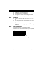
Fuse replacement
1. To replace a fuse, pull the top of the fuse holder.
2. Replace the fuse with a fuse that has the same current rating.
The fuse is a 5 mm x 20 mm slow blow breaking capacity cartridge-type fuse.
Camera voltage
24 VAC
Fuse rating
4 A, 250 VAC
120 VAC
2 A, 250 VAC
230 VAC
2 A, 250 VAC
Table 4.8 Specifications for replacement fuses
NOTE! There is a spare fuse inside the housing.
F.01U.026937 | V 2.0 | 2007.01
User Manual
Bosch Security Systems
UHI/UHO Series UHO-HBPS-10, -50, and UHO-HPS-50 | en
27
5
UHO-HBPS-10, -50, and UHO-HPS-50
5.1
Camera/lens wiring
Installation for these models is in accordance with
Section 4 Installation, except as noted below.
!
CAUTION! Use only 24 VAC power for UHO-HBPS-10 models.
These models have female connectors to prevent them from
being connected to the mating connector that is provided with
UHO-HPS-50 and UHO-HBPS-50 models that require 230 VAC.
Ensure that 230 VAC is not applied to the male mating
connector.
All electrical power connections are made through the 4-pin
connector. Cable Requirements for the 4-pin connector:
6.0 mm (0.24 in) to 12.0 mm (0.47 in)
1.
Cut the power cord on 230 VAC camera models, leaving
enough cable for connection to the terminal block. Strip no
less than 6 mm (0.25 in) and no more than 8 mm (0.31 in)
of insulation away from the wire. Be sure not to nick the
wires.
2.
Insert the power cord through the back shell assembly and
strain relief. See Figure 5.1).
Sealing gasket
Cable nut
24 VAC ONLY!
Male clamping
ring
Metal washer
Internal strain
relief
230 VAC ONLY!
Female clamping
ring
Fig. 5.1 Mating connector 4-pin assembly
Bosch Security Systems
User Manual
F.01U.026937 | V 2.0 | 2007.01
28 en | Operation
UHI/UHO Series
3.
The terminal block provided on these units accepts wire
ranging from 0.5 mm2 to 2.5 mm2 (20 AWG to 14 AWG).
When using larger wire sizes, splice to a smaller size wire
at the terminal block end.
4.
Connect the power input cable to the screw terminals on
the provided mating connector. See Figure 5.1 and
Table 5.1.
Pin
1
2
3
4
Function
AC neutral
AC live
No Connection
Ground
Harness wire color
Blue
Brown
Do not use
Green/yellow
Table 5.1 4-pin wiring connections
5.2
Video coax connection
!
6
CAUTION!
Use only cables meeting specifications in Section 4.3 Cable
requirements for wiring video coax connections.
1.
A video connection is provided on the rear of the housing.
Connect video cable to the housing using a BNC connector.
2.
An internal video connection is provided. Connect the BNC
cable to the camera.
Operation
These housings require no operational adjustments other than
camera/lens adjustments.
7
Maintenance
No special maintenance is required other than occasional cleaning the window. The window can be cleaned with water or any
non-aggressive liquid.
F.01U.026937 | V 2.0 | 2007.01
User Manual
Bosch Security Systems
UHI/UHO Series Exploded view | en
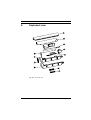
8
29
Exploded view
Fig. 8.1 Exploded view
Bosch Security Systems
User Manual
F.01U.026937 | V 2.0 | 2007.01
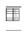
30 en | Exploded view
UHI/UHO Series
1.
Sunshield (ZYB01)
7.
Non-feed through base plate
(DZ4P1)
2.
Top cover (XG001)
8.
Window + window defrosters:
24 VAC (BTQ24)
120 VAC (BJQ15)
23 VAC (BJQ23)
3.
Bottom cover plus latches, glance 9.
version (XDF01)
4.
Bottom cover plus latches, 4 pin
version (XD4P1)
10. Bracket for UHI series (FZ001)
Bracket + PCB/24 VAC heater, no
blower (FZP24)
Bracket + PCB/24 VAC heater,
incl. blower (FPF24)
Bracket + PCB/230 VAC heater,
no blower (FZP23)
Bracket + PCB/230 VAC heater,
incl. blower (FPF23)
Bracket + PCB/120 VAC heater,
incl. blower (FPF12)
5.
Front window holder (QG001)
11. Camera tray-zoom lens version,
(SP001)
Camera tray-type A
(SP002)
6.
Feed-through base plate (DZFT1) 12. Accessory bag (not shown)
(PJB01)
Main heater:
24 VAC (JRP24)
120 VAC (JRP12)
230 VAC (JRP23)
Table 8.1 Parts list
F.01U.026937 | V 2.0 | 2007.01
User Manual
Bosch Security Systems
Bosch Security Systems
Robert-Koch-Straße 100
D-85521 Ottobrunn
Germany
Telefon
089 6290-0
Fax
089 6290-1020
www.boschsecuritysystems.com
© Bosch Security Systems, 2007