1
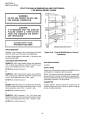
IMPORTANT
WARNING: IMPROPER INSTALLATION, ADJUSTMENT,
ALTERATION, SERVICE OR MAINTENANCE CAN CAUSE
PROPERTY DAMAGE, INJURY OR DEATH. READ THE
INSTALLATION, OPERATING AND MAINTENANCE INSTRUCTIONS THOROUGHLY BEFORE INSTALLING OR
SERVICING THIS EQUIPMENT
FOR YOUR SAFETY
Do not store or use gasoline or other flammable vapors
or liquids in the vicinity of this or any other appliance.
The information contained in this manual is important for the proper
installation, use, and maintenance of this oven. Adherence to these
procedures and instructions will result in satisfactory baking results
and long, trouble free service. Please read thismanual carefully and
retain it for future reference.
Errors: Descriptive, typographic or pictorial errors are subject to
correction. Specifications are subject to change without notice.
ii
THE REPUTATION YOU CAN COUNT ON
For over a century and a half, The Blodgett Oven Company has been building
ovens and nothing but ovens. We’ve set the industry’s quality standard for all
kinds of ovens for every foodservice operation regardless of size, application
or budget. In fact, no one offers more models, sizes, and oven applications than
Blodgett; gas and electric, full-size, half-size, countertop and deck, convection, Cook’n Hold, Combi-Ovens and the industry’s highest quality Pizza
Oven line. For more information on the full line of Blodgett ovens contact your
Blodgett representative.
iii
iv
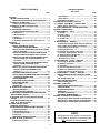
TABLE OF CONTENTS
TABLE OF CONTENTS
(Continued)
Page
Page
SECTION 1
I. MODEL IDENTIFICATION .............................................. 1
SERIES BE3240 ELECTRICAL SPECIFICATIONS....... 2
II. PRINCIPLE OF AIR FLOW ............................................. 3
A. Heat Transfer and How It Works .............................. 3
II. PRINCIPLE OF AIR FLOW (Continued) ........................ 4
B. Air Fingers ................................................................. 4
III. COMPONENT FUNCTION ............................................ 5
A. Conveyor Motor and Conveyor Belt ........................ 6
B. Blower Fan ................................................................. 6
C. Electric Heaters ........................................................ 6
D. Window ....................................................................... 6
E. Cooling Fan ................................................................ 7
F. Air Fingers and Blank Plates - See Figure 1-9 ......... 8
SECTION 2
I. UNLOADING ................................................................... 9
BE3240 OVEN INSTALLATION
REQUIRED KITS AND EQUIPMENT ........................ 10
PARTS LIST FOR SERIES BE3240 ELECTRIC OVEN
INSTALLATION KIT ................................................ 1 0
PARTS LIST FOR BE3240 SERIES SINGLE OVEN
OPTION - BASE W/15″″ LEGS & TOP P/N 34832 ..... 11
PARTS LIST FOR BE3240 SERIES DOUBLE OVEN
OPTION - BASE W/6″ LEGS,CASTERS & TOP
P/N 34833 ................................................................ 12
PARTS LIST FOR BE3240 SERIES DOUBLE OVEN
OPTION - BASE W/CASTERS & TOP
P/N 34831 ................................................................ 13
PARTS LIST FOR BE3240 SERIES TRIPLE OVEN
OPTION - BASE w/OUTRIGGERS & TOP
P/N 51139 ................................................................... 14
RESTRAINT CABLE INSTALLATION.......................... 17
UTILITY ROUGH-IN DIMENSIONS AND POSITIONING
FOR BE3240-SERIES OVENS .................................... 18
CIRCUIT BREAKER ..................................................... 18
ELECTRICAL SPECIFICATIONS ................................. 18
ELECTRICAL RATING ................................................. 18
SUPPLY WIRE .............................................................. 18
SUGGESTED ................................................................ 18
II. VENTILATION GUIDELINES .................................... 19
VENTILATION HOOD ................................................... 19
VENTILATION CAPTURE TEST................................... 19
III. ELECTRICAL CONNECTION INFORMATION FOR
BE3240-SERIES OVENS. ........................................... 20
IV. ELECTRIC SUPPLY FOR ELECTRIC-HEATED
OVENS ...................................................................... 20
V. CONVEYOR REAR STOP AND
END STOP INSTALLATION ...................................... 21
SECTION 3 INSTALLATION
I. CONTROL FUNCTIONS ................................................ 23
II. COMPONENT INFORMATION AND LOCATION ......... 24
A. Door Safety Switch .................................................. 24
B. Blower/Heat Switch ............................................ 24
C. Temperature Controller .......................................... 24
D. Conveyor ................................................................. 25
MEASURING CONVEYOR SPEED. ............................. 25
III. STEP-BY-STEP OPERATION ..................................... 26
A. Startup Procedures ................................................. 26
Daily Startup ................................................................. 26
Power Failure ............................................................... 26
B. Shutdown Procedure ...................................................... 26
SECTION 3 INSTALLATION (Continued)
IV. NORMAL OPERATION - STEP-BY-STEP .................. 28
A.Daily Startup Procedure .......................................... 28
V. QUICK REFERENCE: TROUBLESHOOTING ............. 30
SECTION 4 MAINTENANCE
I. MAINTENANCE - DAILY ........................................... 32
A. Exterior .................................................................... 32
B. Cooling Fan .............................................................. 32
C. Conveyor Belt ......................................................... 32
D. Crumb Pans ............................................................ 32
E. Window .................................................................... 32
II. MAINTENANCE - MONTHLY ...................................... 33
A. Removing Conveyor From Oven For Cleaning .... 33
B. Air Fingers Disassembly For Cleaning ................. 35
C. Reassembly of Air Fingers .................................... 36
D. Reinstall End Plugs ................................................. 39
E. Conveyor Reassembly Into Oven.......................... 40
F. Checking Conveyor Belt Tension ......................... 40
G. Conveyor Belt Link Removal ................................ 41
H. Replacing Conveyor Belt ......................................... 42
I. Attaching Drive Chain ............................................ 42
III. MAINTENANCE - EVERY 3 MONTHS ........................ 43
A. Cleaning the Blower/Fan Motor ............................. 43
B. Electrical Terminals ............................................... 44
C. Ventilation ............................................................... 44
D. Checking the Blower/Fan Belt ............................... 44
E. Blower Fan Shaft Bearing Lubrication .................. 45
F. Split-belt Conveyor Shaft Cleaning ........................ 45
IV. MAINTENANCE - EVERY 6 MONTHS .................... 46
BE3240-SERIES ELECTRIC OVEN KEY SPARE
PARTS ...................................................................... 48
KEY SPARE PARTS KIT .............................................. 48
SECTION 5 TROUBLESHOOTING
Troubleshooting Charts ..................................................... 49
SECTION 6 - PARTS LIST
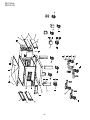
OVEN PANELS, WINDOW AND LEGS ............................ 53
CONTROL PANEL ........................................................... 55
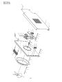
BLOWER AND SHROUD ................................................. 57
CONVEYOR...................................................................... 59
SPLIT BELT CONVEYOR ................................................. 61
MACHINERY COMPARTMENT ....................................... 63
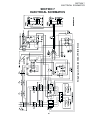
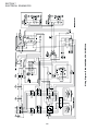
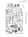
SECTION 7 ELECTRICAL SCHEMATICS
Wiring Diagram, E208-240 50/60, 3PH 4W BE3240 ........ 65
Wiring Diagram, E380-480 50/60, 3PH 5W BE3240 ........ 66
Wiring Diagram, E380V 50/60, 3PH 5W BE3240 .......... 67
v
NOTE
Wiring Diagrams are in Section 7 of this Manual.
The diagram for each oven is also on the lower
inner surface of its Control Console.
NOTES
vi
SECTION 1
DESCRIPTION
SECTION 1
DESCRIPTION
I.
MODEL IDENTIFICATION
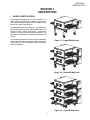
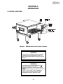
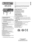
The Blodgett BE3240-Series may be used either as a
single oven or stacked for use as double or triple ovens.
The major difference between the oven models in this
series is the width of the conveyor.
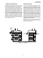
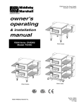
A single BE3240-Series Oven (Figure 1-1) is mounted on a
base pad with legs and casters. A double oven (Figure 1-2)
consists of two, stacked, single ovens. A triple oven
(Figure 1-3) consists of three stacked single ovens. The
lower oven is mounted on a base pad with short legs and
casters.
On a double or triple oven, the ovens operate completely
independent. All ovens use identical controls and components. One oven can be cleaned or serviced, while the
others are operating.
Figure 1-1. Single BE3240 Oven
Figure 1-2. Double BE3240 Oven
Figure 1-3. Triple BE3240 Oven
1
SECTION 1
DESCRIPTION
2
SECTION 1
DESCRIPTION
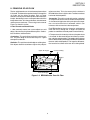
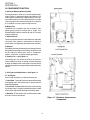
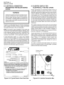
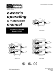
II. PRINCIPLE OF AIR FLOW
The fan-style blower draws air into the oven plenum where
it is heated. The blower then pushes the hot air through the
air fingers into the baking chamber. Each air finger
contains an inner plate and outer plate that form the hot air
into jets, distributing it across a conveyor belt on which the
food product rides. Air is then pulled back into the blower
and the process continues. The curving, black arrows of
Figure 1-4 show this air flow.
reflect more heat. This is the reason that the inside of a
BE3240-Series Oven is light in color: To reflect more heat
back onto the food product.
Convection: This path has to do with moving a volume of
air. It explains why hot air rises and cooler air replaces hot
air. An industrial application of this principle is to incorporate a fan to force the hot air movement, which in turn
increases the heat transfer to the food product.
A. Heat Transfer and How It Works
Each BE3240-Series Oven has a large fan-style blower to
move the hot air through the air fingers and onto the
product to cook/bake the food product most efficiently.
1. Heat constantly moves from a warm object to a cold
object. Heat moves using three different paths: Conduction; Radiation; and Convection.
2. Temperature is the intensity of heat at the point where
it is sensed. As discussed above, heat flows by conduction, radiation and convection. The speed at which the heat
flows is determined by the temperature difference between
the oven and the food product. The larger the difference,
the faster the heat flows to the item that is being baked.
Conduction: This path utilizes surface-to-surface contact. The pizza dough in contact with the pan is a good
example of conduction.
Radiation: This path has to do with objects radiating heat.
Dark objects absorb heat whereas light or shiny objects
Upper Air Fingers
Conveyor Belt(s)
Window
Lower Air Fingers
Figure 1-4. BE3240-Series Oven Air Flow
3
SECTION 1
DESCRIPTION
II. PRINCIPLE OF AIR FLOW (Continued)
B. Air Fingers
Series ovens used to bake pizza have four bottom fingers
and two top fingers. For special product baking requirements, a number of other styles of fingers and finger
arrangements are available from the factory.
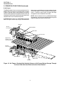
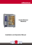
The BE3240-Series Ovens are conveyorized ovens that
employ vertical jets of hot air streaming from air fingers
(Figure 1-5) to give uniform, intense heating. The vertical
streams of hot air provide an exceptional heat transfer rate
and generally bake faster and at lower temperatures than
convection hot air or infrared heating ovens.
NOTE: Some customers have a predetermined finger
arrangement. If you have any questions pertaining to the
finger arrangement, please call the factory.
A BE3240-Series Oven can accommodate up to four
bottom air fingers and four top air fingers. Some BE3240-
Manifold
Air Flow
From Plenum
Manifold Baffle
Outer Plate
Inner Plate
High Velocity
Columns of Air
on Food Product
Air Flow
From Plenum
Manifold Baffle
Inner Plate
Outer Plate
Manifold
Figure 1-5. Air Fingers, Showing High-Velocity Columns of Air Formed During Passage Through
the Inner Plate and Outer Plate to Heat the Food Product.
4
SECTION 1
DESCRIPTION
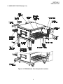
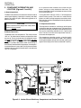
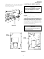
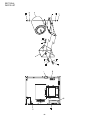
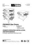
III. COMPONENT FUNCTION (Figure 1-6)
Figure 1-6. BE3240-Series Oven Components Locations
5
SECTION 1
DESCRIPTION
III. COMPONENT FUNCTION
A. Conveyor Motor and Conveyor Belt
The conveyor belt is driven by a variable-speed electric
motor (Figure 1-7) operating through a gear reducer. The
motor speed is controlled by a digital control. The stainless-steel wire belt can travel in either direction at variable
rates ranging from 3 minutes to 30 minutes; this is the time
that a product can take to pass through the oven.
B. Blower Fan
The blower fan is located at the rear of the oven. This
blower forces heated air through the air fingers. The
BLOWER/HEAT switch must be set to “ON” or “I” for oven
warmup and baking.
C. Electric Burner
There are six heater elements mounted on the inside of the
rear panel. Each element is connected to an electrical
control which is energized by the temperature controller.
D. Window
A window on the front of the oven permits viewing the items
being baked and provides access to the oven for items that
do not require full baking time, such as sandwiches,
cookies, small items, or cheese-melting processes.
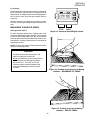
E. Cooling Fan — See Figure 1-8
The cooling fans are located in the back of the oven.
These cooling fans draw air through its grille, blowing it
through the blower motor compartment and the control
compartment into the oven top and exhausted out the front
louvers.
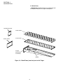
F. Air Fingers and Blank Plates - See Figure 1-9
F1. Air Fingers
An Air Finger Assembly is made up of three parts:
1. Outer Plate - The Outer Plate is the removable covering
with tapered holes, which direct the air stream onto the
product being baked.
2. Inner Plate -The perforated Inner Plate is vital in forming
the unique air jets. It must be assembled into the manifold
with its holes aligned with the holes of the outer plate.
3. Manifold - The Manifold is the assembly which slides
on tracks into the oven plenum.
Figure 1-7. Machinery Compartment
Components
6
SECTION 1
DESCRIPTION
Figure 1-8. Cooling Fan
7
SECTION 1
DESCRIPTION
F2. Blank Plates
1. Blank Plates- The Blank Plates are available to install
on the plenum where an air finger is not required.
Half Blank Plate
Outer Plate
Blank Plate
Inner Plate
Finger
Manifold
Assembly
Baffle
Figure 1-9. Blank Plates (two sizes) and an Air Finger.
8
SECTION 2
INSTALLATION
SECTION 2
INSTALLATION
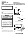
NOTE: The oven, when installed, must be electrically
grounded in accordance with local codes, or in the absence of local codes, with the National Electrical Code
(NEC), or ANSI/NFPA70.
I. UNLOADING
Your Blodgett BE3240-Series Oven is shipped partially
assembled. It will arrive in a carton on a crate.
Carton size for a BE3240-Series Oven is:
NOTE
84″ (2134mm) Long ×
There must be adequate clearance between
the oven and any adjacent combustible construction. Clearance must also be provided
for servicing and for operation.
58″ (1473mm) Wide ×
44″ (1118mm) High ×
The crate and carton must be examined before signing the
Bill of Lading. Report any visible damage to the transport
company, and check for the proper number of crates. If
apparent damage is found, make arrangements to file a
claim against the carrier. Surface Interstate Commerce
Regulations (U.S.A.) require that the claim must be
initiated by the consignee within 10 days from the date that
the shipment is received.
CAUTION
It is required that the oven be placed under a
ventilation hood for adequate air supply and
ventilation.
CAUTION
A Pre-installation Procedures Manual is attached to the
exterior wall of the carton. This manual contains detailed
instructions on unpacking and moving the oven(s) to the
operating site. When the transport company notifies you of an
impending delivery, arrange to have a forklift at your facility
to unload the carton(s).
Do not obstruct the flow of combustion and
ventilation air to and from your oven. Do not
obstruct the ventilation holes in the Control Panel.
CAUTION
On ovens with the Machinery Drive Compartment
located at the right end, a minimum clearance of
0″ to a left side wall, 18″ to a right side wall and 6″
from a back wall to air openings at the rear of the
oven must be maintained. On ovens with the
machinery/drive compartment located at the left
end, a minimum clearance of 0″ to a right side
wall, 18″ to a left side wall and 6″ from a back wall
to air openings at the rear of the oven must be
maintained.
Instructions for stacking the ovens is continued in a
separate manual used by Blodgett Authorized Installers.
If you have a door wider than the carton, simply move the
carton into your facility and arrange an appointment with
your Blodgett Authorized Installer.
If your door is narrower than the carton, then the oven will
have to be unpacked. Follow the directions shown in the
Pre-Installation Procedures Manual.
For servicing and cleaning, a minimum of 18″
clearance from all walls is recommended.
9
SECTION 2
INSTALLATION
BE3240 OVEN INSTALLATION
REQUIRED KITS AND EQUIPMENT
TYPE
OF
INSTALLATION
BE3240
Gas Oven
Installation
Kit P/N
50663
BE3240 Single
Oven Option
Base w/15″ Legs,
Casters & Top
Kit P/N
34832
BE3240 Single Gas Oven
1
1
BE3240 Double Gas Oven
2
BE3240 Triple Gas Oven
3
BE3240 Double
Oven Option
Base w/6″ Legs,
Casters & Top
Kit P/N
34833
BE3240 Double
Oven Option
Base w/Casters
& Top
Kit P/N
34831
1
1
BE3240 Triple
Oven Option
Base w/Casters
& Top
Kit P/N
51139
1
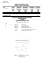
PARTS LIST FOR SERIES BE3240 GAS OVEN
INSTALLATION KIT
P/N 50633
(Two required for double oven)
(Three required for triple oven)
ITEM
NO.
QTY
PART NO.
1
1
33900-0032
FLEXIBLE GAS HOSE
2
1
35000-1103
CONVEYOR END STOP
3
1
35900-0148
CONVEYOR LEFT REAR STOP
4
1
50664
5
1
1002040
DESCRIPTION
SERIES BE3240 OWNER/OPERATOR MANUAL
SERVICE AGENCY DIRECTORY
Figure 2-1. BE3240-Series Gas Oven
Installation Parts
10
SECTION 2
INSTALLATION
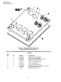
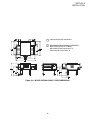
Figure 2-2. Model BE3240 Single Oven
Option Base with Legs and Top
PARTS LIST FOR BE3240 SERIES SINGLE OVEN OPTION - BASE w/15² LEGS & TOP
P/N 34832
ITEM
NO.
1
2
3
4
5
6
7
8
9
10
QTY
1
4
2
2
32
32
32
4
1
1
PART NO.
37900-0025
37900-0024
22290-0009
22290-0010
220373
21416-0001
21422-0001
21256-0008
22450-0228
33486
DESCRIPTION
COMPLETE BASE WELDMENT
TOP PLATE, LEG WELDMENT
SWIVEL CASTER W/BRAKE FLAT PLATE
SWIVEL CASTER FLAT PLATE
3/8″-16 × 1″ HEX SCREW,SST
3/8″ FLAT WASHER, SS
3/8″ SPLIT LOCK WASHER, ZP
SCREWS FOR TOP 10-32 × 3/8″ 18-8, SL TRUS S
RESTRAINT CABLE ASSEMBLY
TOP COVER 304 PANEL
11
SECTION 2
INSTALLATION
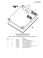
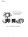
Figure 2-3. Model BE3240 Double Oven
Option Base with Legs and Top
PARTS LIST FOR BE3240 SERIES DOUBLE OVEN OPTION - BASE w/6″″ LEGS, CASTERS & TOP
P/N 34833
ITEM
NO.
1
2
3
4
5
6
7
8
9
10
QTY
1
4
2
2
32
32
32
4
1
1
PART NO.
37900-0025
37900-0102
22290-0009
22290-0010
220373
21416-0001
21422-0001
21256-0008
22450-0228
33486
DESCRIPTION
COMPLETE BASE WELDMENT
TOP PLATE, LEG WELDMENT
SWIVEL CASTER W/BRAKE FLAT PLATE
SWIVEL CASTER FLAT PLATE
3/8″-16 × 1″ HEX SCREW,SST
3/8″ FLAT WASHER, SS
3/8″ SPLIT LOCK WASHER, ZP
SCREWS FOR TOP 10-32 × 3/8″ 18-8, SL TRUS S
RESTRAINT CABLE ASSEMBLY
TOP COVER 304 PANEL
12
SECTION 2
INSTALLATION
Figure 2-4. Model BE3240 Double Oven
Option Base with Casters and Top
PARTS LIST FOR BE3240 SERIES DOUBLE OVEN OPTION - BASE w/CASTERS & TOP
P/N 34831
ITEM
NO.
1
2
3
4
5
6
7
8
9
QTY
1
2
2
32
32
32
4
1
1
PART NO.
37900-0025
22290-0009
22290-0010
220373
21416-0001
21422-0001
21256-0008
22450-0228
33486
DESCRIPTION
COMPLETE BASE WELDMENT
SWIVEL CASTER W/BRAKE FLAT PLATE
SWIVEL CASTER FLAT PLATE
3/8″-16 × 1″ HEX SCREW,SST
3/8″ FLAT WASHER, SS
3/8″ SPLIT LOCK WASHER, ZP
SCREWS FOR TOP 10-32 × 3/8″ 18-8, SL TRUS S
RESTRAINT CABLE ASSEMBLY
TOP COVER 304 PANEL
13
SECTION 2
INSTALLATION
Figure 2-5. Model BE3240 Triple Oven
Option Base with Outriggers and Top
PARTS LIST FOR BE3240 SERIES TRIPLE OVEN OPTION - BASE w/CASTERS & TOP
P/N 51139
ITEM
NO.
1
2
3
4
5
6
7
8
9
10
11
12
13
14
15
16
QTY
1
4
2
2
4
4
32
32
32
16
8
8
8
4
1
1
PART NO.
54606
45209
22290-0009
22290-0010
45206
45205
220373
21416-0001
21422-0001
21172-0004
21216-0018
21416-0003
21426-0004
21256-0008
22450-0228
33486
DESCRIPTION
COMPLETE BASE WELDMENT
QUAD OUTRIGGER WELDMENT
SWIVEL CASTER, W/BRAKE FLAT PLATE
SWIVEL CASTER, FLAT PLATE
INSERT,QUAD ADJUSTMENT FOOT
SPACER,QUAD CASTER
3/8″-16 × 1″ HEX BOLT, SST
3/8″ FLAT WASHER, SS
3/8″ SPLIT LOCK WASHER, ZP
3/8″-16 NYLON INSULATED LOCKNUT, ZC
1/2″-13 × 1-1/4″ 18-8 HEX CAPSCREW
1/2″ 18-8 FLAT WASHER
1/2″ 18-8 LOCK WASHER
SCREWS FOR TOP 10-32 × 3/8″ 18-8, SL TRUS S
RESTRAINT CABLE ASSEMBLY
TOP COVER 304 PANEL
14
SECTION 2
INSTALLATION
2
2
2
1
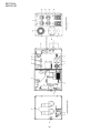
Conduit for Electrical Connections
2
RECOMMENDED MINIMUM CLEARANCES:
Rear of Oven to Wall - 6″ (150mm)
Non-control End of Oven to Wall - 0″
Control End of Oven to Wall - 0″
1
Figure 2-6. MODEL BE3240 SINGLE OVEN DIMENSIONS
15
SECTION 2
INSTALLATION
1
Conduit for Electrical Connections
2
RECOMMENDED MINIMUM CLEARANCES:
Rear of Oven to Wall - 6″ (150mm)
Non-control End of Oven to Wall - 0″
Control End of Oven to Wall - 0″
2
2
2
1
Figure 2-7. MODEL BE3240 DOUBLE OVEN DIMENSIONS
16
SECTION 2
INSTALLATION
2
2
1
Conduit for Electrical Connections
2
RECOMMENDED MINIMUM CLEARANCES:
Rear of Oven to Wall - 6″ (150mm)
Non-control End of Oven to Wall - 0″
Control End of Oven to Wall - 0″
2
1
Figure 2-8. MODEL BE3240 TRIPLE OVEN DIMENSIONS
RESTRAINT CABLE INSTALLATION
Install the restraint cable assembly on the oven, as shown
in Figure 2-9.
Figure 2-9. Restraint Cable Assembly Installation
17
SECTION 2
INSTALLATION
UTILITY ROUGH-IN DIMENSIONS AND POSITIONING
FOR BE3240-SERIES OVENS
5
WARNING
DO NOT USE CONDUIT OR GAS LINE
FOR GROUND CONNECTION.
ON
6
OFF
2
3
1
24"
610mm
2
CAUTION
6
IT IS REQUIRED THAT THE OVEN BE
PLACED UNDER A VENTILATION
HOOD FOR ADEQUATE AIR SUPPLY
AND VENTILATION.
ON
27"
686mm
OFF
2
3
2
4
13-1/2"
343mm
24"
610mm
ELECTRIC AND GAS SUPPLY TO BE
PROVIDED BY CUSTOMER
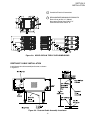
Suggested dimensions are shown; utility code
requirements supersede any factors shown.
ELECTRICAL SAFETY SWITCH
15 Amp circuit breaker / fused disconnect switch with
lockout/tagout electrical shutoff for each oven. Wire
each oven separately.
Figure 2-10. Typical BE3240-Series Oven(s)
Installation
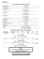
ELECTRICAL SPECIFICATIONS
GAS SAFETY VALVE
DOMESTIC or EXPORT: 208-240V blower motor,
1 phase, 4.1 Amp draw, 50/60 Hz, 208-240V control
circuit, 2 poles, 3-wire system per oven (2 hot, 1 grd).
A 3/4″ (19mm) ID (inner diameter) full-flow, gas shutoff
valve. A separate connection and valve must be provided
for each oven, as shown in Figure 2-9.
Do NOT use conduit for ground.
REQUIRED GAS SUPPLY PRESSURE
GAS RATING
Natural: 6″ to 12″ water column (13.8 to 29.9 mbar)
Model PS540 is 110,000 BTU/hour (27,720 kcal), 32.2 kW/hr.
Propane: 11.5″ to 12″ water column (28.7 to 29.9 mbar)
MINIMUM GAS METER RATING
450 ft3/hour (12.6m3/h) for 1 or 2 ovens;
SUGGESTED
Add 180 cu. ft./hr (5.1 m3/h) for each additional oven.
If space permits, electric and gas service should be
located near the control console end of the oven(s) to allow
convenient access to safety switches and valves.
Minimum rating does not take other gas appliances into
consideration. Gas consumption varies at each site. Total
BTU/hr (kcal/hr) must be calculated during high flame
operation for each appliance to determine if the meter
needs to be larger.
USER SUPPLIED ITEMS (Figure 2-9)
ITEM
1
2
3
4
5
6
MINIMUM GAS PIPE SIZE
Natural: 2″ (51mm) ID for 1, 2, or 3 ovens with runs up
to 200 ft. (61m).
Must be a dedicated line.
Runs over 200 ft, (61m) consult factory.
Propane: 2″ (51mm) ID for 1, 2, or 3 ovens with runs up
to 200 ft. (61m).
Must be a dedicated line.
Runs over 200 ft, (61m) consult factory.
18
DESCRIPTION
2″ (51mm) × 2″ (51mm) × 3/4″ (19mm) TEE
3/4″ (19mm) × 3″ (76mm) NIPPLE
3/4″ (19mm) FULL FLOW GAS SHUTOFF VALVE
2″ (51mm) × 3/4″ (19mm) 90° REDUCER ELBOW
2″ (51mm) ID GAS SUPPLY PIPE LINE - NATURAL GAS
15 AMP TOGGLE SWITCH - 2 POLE for GAS
SECTION 2
INSTALLATION
II. VENTILATION GUIDELINES
VENTILATION HOOD
A mechanically driven ventilation system is required for
the BE3240 Series Blodgett conveyorized gas ovens. The
minimum hood canopy dimensions are outlined below.
The rate of air flow exhausted through the ventilation
system is generally between 1400 and 2500 cu. ft./min.
(40 and 70 m3/min), but may vary depending on the oven
configuration and hood design. To avoid a negative
pressure condition in the kitchen area, return air must be
brought back to replenish the air that was exhausted. A
negative pressure in the kitchen can cause heat related
problems to the oven components as if there were no
ventilation at all. The best method of supplying return air
is through the heating, ventilation and air conditioning
system. Through they system, the air can be temperature
controlled for summer and winter. Return air can be
brought in directly from outside the building, but detrimental affects can result from either extreme seasonal hot and
cold temperature from the outdoors.
Local codes and conditions vary greatly from one area to
another and must be complied with. Following are the
suggested requirements for good ventilation. Please remember these are recommendations or guidelines, you
may have a special condition or problem that will require
the services of a ventilation engineer or specialist. Proper
ventilation is the oven owner’s responsibility. Improper
ventilation can inhibit oven performance. It is recommended that the ventilation and duct work be checked out
every three months. Grease filters in the intake of the hood
may be required by local codes.
NOTE: Return air from fan driven system within the hood
must not blow at opening of bake chamber or poor oven
baking performance will result.
2″ (51mm)
minimum.
To allow
stacking of
ovens.
21-1/2″
(546mm)
minimum
18″
(458mm)
minimum
8″ (203mm)
minimum
Figure 2-11. Vent Hood
19
1″ (25mm)
minimum
SECTION 2
INSTALLATION
factory-authorized installer can perform the initial
startup of the oven.
VENTILATION CAPTURE TEST
It is recommended that a 30 second smoke candle test be
performed on your ventilation hood system. Follow the
steps below to complete the ventilation smoke test.
Check the oven data plate (Figure 2-11) before making any
electric supply connections. Electric supply connections
must agree with data on the oven data plate.
All tests are to be done on single ovens or lower units of
a double or triple oven. We recommend you wear protective gloves when performing this test. At no time should
food be present when the smoke test is being conducted.
Also check that no fire suppression system will be
activated by the smoke.
NOTE: The electric supply installation must satisfy the
requirements of the appropriate statutory authority, such
as the National Electrical Code (NEC), ANSI/NFPA70,
(U.S.A.); the Canadian Electrical Code, CSA C22.2; the
Australian Code AG601; or other applicable regulations.
1. Turn ventilation system on.
A fused disconnect switch or a main circuit breaker
(customer furnished) MUST be installed in the electric
supply line for each oven; it is recommended that this
switch/ circuit breaker have lockout/tagout capability. The
electric supply connection must meet all national and local
electrical code requirements. Copper is the recommended
material for the electrical supply conductors.
2. Turn oven(s) on and allow to heat up to customers
normal operating temperature, or a minimum of
480°F (248°C).
3. Turn conveyor off. Place a 30 second smoke candle in
a pie or cake pan which is no higher than 3″ (76mm).
4. Open the front oven window. Next, light the smoke
candle in the pan and then slide the pan into the center of
the bake chamber on the conveyor belt and close the
window.
IV. ELECTRIC SUPPLY FOR GASHEATED OVENS
Supply voltages for all gas ovens (except one 200 - 220V
oven for export) can range from 208 to 240VAC, 1 phase.
Ampere requirements for each oven can be handled via a
fused disconnect switch or main circuit breaker.
5. The ventilation hood should capture 90% to 100% of the
smoke produced by the candle.
NOTE: The electric supply installation must satisfy the
requirements of the appropriate statutory authority, such
as the National Electrical Code (NEC), ANSI/NFPA70,
(U.S.A.); the Canadian Electrical Code, CSA C22.2; the
Australian Code AG601; or other applicable regulations.
III. ELECTRICAL CONNECTION
INFORMATION FOR BG3240-SERIES
OVENS.
The supply conductors must be of the size (#14 AWG,
copper) recommended. (Refer to the wiring diagrams of
Section 7.) All gas oven electric supply connections are
made via the electrical junction box on the rear of the oven
(Figure 2-12). The power lines then connect through an
oven safety switch (on the control console door frame) to
the oven circuits. Opening the door interrupts electric
power to the oven.
WARNING
Authorized supplier personnel normally accomplish the connections for the ventilation system,
electric supply, and gas supply, as arranged by
the customer. Following these connections, the
CAUTION
Before connecting incoming power to the oven,
measure the voltage of each input leg to
neutral. The expected voltage is approximately
120 volts. Any voltage reading exceeding 130
volts indicates that the supply has a ‘high’ leg.
Figure 2-12. Typical Electric Oven Data Plate
Figure 2-13. Junction Connection Box
20
SECTION 2
INSTALLATION
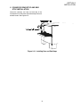
V. CONVEYOR REAR STOP AND END
STOP INSTALLATION
Locate the conveyor rear stop and end stop in the
installation kit. Install the rear stop and end stop at the exit
end of the oven. See Figure 2-14.
Figure 2-14. Installing Rear and End Stops
21
SECTION 2
INSTALLATION
NOTES
22
SECTION 3
OPERATION
SECTION 3
OPERATION
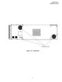
I. CONTROL FUNCTIONS
Figure 3-1. BE3240-Series Oven Control Functions
WARNING
The burner cannot operate and gas cannot flow
through the burner without electric power. Do
NOT attempt to operate the oven during a power
outage.
WARNING
A possibility of injury from rotating parts and
electric shock exists in this oven.
Never disassemble or clean the oven with the
BLOWER switch or any other oven control turned
“ON” or “I”. Turn “OFF” or “O” and lockout or
tagout all electric power to the oven before
attempting to clean or service this oven.
23
SECTION 3
OPERATION
An air pressure switch monitors the air flow from the
blower, acting as a safety interlock for the burner. The
burner cannot light, if the air switch does not sense air flow
off the main blower fan.
II. COMPONENT INFORMATION AND
LOCATION (Figures 3-1 and 3-2)
A. Door Safety Switch
The Door Safety Switch is located at the lower left side of
control panel opening. Opening the control panel door
permits this switch to open, disconnecting power to all
electrical controls.
Turning the HEAT switch to “ON” or “I” will energize the
electric heating system. This switch is in series with the
blower fan motor and high temperature override switch.
Both switches must be closed before the heating elements
an be energized.
CAUTION
C. Temperature Controller
Do NOT touch the wires going to this safety switch.
Current is always present.
The temperature controller is a solid-state, on/off type to
maintain the operator-set temperature. The temperature
controller continuously monitors the oven temperature and
turns on the modulating solenoid valve in a gas-heated
oven. The heat is on for the time required to maintain a
constant oven temperature.
B. Blower/Heat Switch
The blower switch has two positions. The switch must be
“ON” or “I” for the burner to come on and permit the oven
to warm up. The fan circulates the air throughout the oven
and must stay on during baking and during the cool down
cycle above 200°F (93°C) to prevent blower bearing
damage. To protect the blower motor and bearings a
thermostatic override is built into the oven. If the temperature inside the oven is over 180°F (82°C) the main blower
will continue to run after the blower switch is turned to the
“OFF” or “O” position.
The temperature controller contains a low-limit switch
which allows the oven to cool down to 200°F (93°C) before
shutting off the blower. A high-limit indication (ALM 1) will
appear on the display if the oven reaches 650°F (343°C).
Figure 3-2. Interior View of Machinery Compartment and Control Console
24
SECTION 3
OPERATION
D. Conveyor
The on-off switch for the conveyor motor is on the control
panel. Also on the control panel is the digital conveyor
speed control. The digital control can be adjusted from 3
min. to 30 min. bake time (conveyor speed). Refer to
Figure 3-3.
Conveyor speed is measured by the amount of time it
takes for an item to go through the bake chamber of the
oven.
MEASURING CONVEYOR SPEED.
See Figures 3-4 and 3-5.
Figure 3-3. Conveyor Speed Digital Control
To check conveyor speed, place a product item at the
entrance end of baking chamber as shown. Time how long
it takes for the leading edge of the item to go from the
entrance end of the baking chamber to the exit end. This
should be the conveyor speed shown on the conveyor
speed digital control.
NOTE: In Figures 3-4 and 3-5, the oven shown is with the
conveyor running right to left.
WARNING
Possibility of injury from rotating parts and
electrical shock exist in this oven.
Never disassemble or clean the oven with the
blower switch or any other part of the oven
turned “ON” or “I”. Turn “OFF” or “O” and
lockout or tagout all electrical power to the
oven before attempting to clean or service
this oven.
Figure 3-4. Product at entrance end of baking
chamber – BEGINNING OF TIMING
Figure 3-5. Product at exit end of baking
chamber – END OF TIMING
25
SECTION 3
OPERATION
4. Set the temperature controller to the desired baking
temperature. See section on bake times to determine
desired temperature.
WARNING
OVEN MUST BE KEPT CLEAR OF
COMBUSTIBLES AT ALL TIMES.
NOTE: For complete temperature controller operation
instructions refer to Step C.
III. STEP-BY-STEP OPERATION
6. Close front window.
Control Panel (On split belt ovens, two conveyor speed
controls are mounted on the control panel.)
A. Startup Procedures
7. Oven will reach a baking temperature of 500°F (232°C)
in approximately 10 minutes. Allow the oven to cycle for
30 minutes after it has reached desired bake temperatue.
The oven is now ready for baking.
Daily Startup
Power Failure
1. Turn the BLOWER/HEAT switch (Figure 3-6) to the
“ON” or “I” position. This starts the main blower fan and the
cooling fan. The blower circulates air through the air fingers
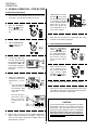
and must stay on during the cooking or baking process.
In case of power failure, turn off all switches; open oven
window and remove product. After power has been
reestablished follow normal startup procedure.
2. Check to see if the cooling fan (see Figure 1-8) is
operating when the blower switch (see Figure 3-6) is turned
“ON” or “I”. The cooling fans cool the control components
and burner blower motor. The cooling fan, located at the
rear of the electrical control cabinet blows air into and
through the cabinet. Air is exhausted through the front of
the cabinet and also out the front of the oven. Refer to Daily
Maintenance Section for fan intake checking procedure.
B. Shutdown Procedure
1. Turn the BLOWER/ HEAT switch to “OFF” or “O”.
NOTE: The blowers will remain on until the oven temperature cools down to 200°F (93°C) at which time they will stop
automatically.
2. Make certain that there are no products left on the
conveyor inside the oven. Turn the CONVEYOR switch
to “OFF” or “O”.
IMPORTANT NOTE
3. Open the oven window.
The cooling fan operates when the BLOWER/
HEAT switch is turned “ON” or “I”. It must operate
to keep the control console below 140°F (60°C).
3. Turn the CONVEYOR switch (Figure 3-6) to the “ON” or
“I” position. This starts the conveyor belt moving through
the oven. Set the conveyor speed for the desired baking
time. Refer to the following Procedures E, F and G.
26
SECTION 3
OPERATION
Figure 3-6. Control Panel
27
SECTION 3
OPERATION
II. NORMAL OPERATION - STEP-BY-STEP
A.Daily Startup Procedure
7.
1.
2.
3.
4.
5.
Check that the circuit breaker/fused disconnect is in the
on position. Check that the window is closed.
Turn the "CONVEYOR"
(
) switch to the
“ON” ("I") position.
Adjust the temperature
controller to a desired set
temperature, if necessary.
•
•
6.
perature ( ) key to show
the Actual Temperature
in the display, and wait
for the "ACTUAL TEMP"
light to turn on. This allows you to monitor the
oven temperature as it
rises to the setpoint.
Turn the "BLOWER/
HEAT" ( )( ) switch
to the “ON” ("I") position.
If necessary, adjust the
conveyor speed setting
by pressing the
or
pushbuttons on the conveyor speed controller to
change the displayed
bake time.
wait
for
8.
Allow the oven to preheat for 10 minutes after it has
reached the set point temperature.
B.
DAILY SHUTDOWN PROCEDURE
1.
Turn the "BLOWER"/
"HEAT" ( )( ) switch
to the "OFF" ("O") position. Note that the blowers will remain in operation until the oven has
cooled to below 200°F
(93°C).
2.
Make certain that there
are no products left on
the conveyor inside the
oven. Turn the "CON) switch to
VEYOR" (
the "OFF" ("O") position.
3.
Open the window to allow the oven to cool faster.
4.
After the oven has cooled and the blowers have turned
to the “OFF” or “O” position, switch the circuit breaker/fuse
disconnect to the “OFF” or “O” position.
or
+
wait
for
Press the Set Point
and Unlock keys at
the same time. Wait
for the "SET PT" light
to turn on.
Press the Up Arrow
and Down Arrow
Keys as necessary
to adjust the setpoint.
(Optional) Press the Tem-
or
CAUTION
In case of power failure, turn all switches to the “OFF”
("O") position, open the oven window, and remove
the product. After the power has been restored,
perform the normal startup procedure. IF THE OVEN
WAS SWITCHED OFF FOR LESS THAN 5 MINUTES,
WAIT FOR AT LEAST FIVE MINUTES BEFORE RESTARTING THE OVEN.
Wait for the oven to heat to the setpoint temperature.
Higher setpoint temperatures will require a longer wait.
The oven can reach a temperature of 500°F (232°C) in
approximately 5 minutes.
28
SECTION 3
OPERATION
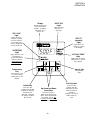
"HEAT ON"
Light
Display
Shows the Set Point
or the Actual Temperature in degrees
Fahrenheit (F) or
Celsius (C).
Lights when the
burner is in
operation.
"SP LOCK"
Light
Lights when the
set point is locked
out from changes.
This setting can
only be changed by
service personnel.
"SET PT"
(setpoint)
Light
Lights when the
set point is shown
in the display.
OVERTEMP
Light
"ACTUAL TEMP"
Light
Lights when the oven
temperature is
greater than 650°F
(343°C). Refer to
Quick Reference:
Troubleshooting in
this section.
Lights when the Actual
Temperature is shown
in the display.
Service Key
Temperature
Key
Service use
only.
Press this key once
to view the Actual
Temperature in the
Display.
Set Point Key
Unlock Key
Press this key
together with the Set
Point Key to allow the
Set Point to be
changed. Changes
can only be made for
60 seconds.
Up Arrow and Down
Arrow Keys
Press these keys to
adjust the Set Point up or
down. If the Set Point will
not change, refer to Set
Point Key and Unlock Key
in this section.
29
Press this key
together with the
Unlock Key to allow
the Set Point to be
changed.
Changes can only be
made for 60 seconds.
SECTION 3
OPERATION
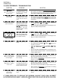
IV. QUICK REFERENCE: TROUBLESHOOTING
SYMPTOM
PROBLEM
SOLUTION
The oven temperature exceeded 650°F (343°C), and
the burner was automatically shut down.
•
Follow the procedures under Daily Shutdown Procedures in
this section to shut down the oven. Contact your Middleby
Marshall Authorized Service Agent to determine and correct the
cause of the condition to prevent damage to the oven.
Oven will not
turn on at all
Electrical power may not be
reaching the oven, or the
controls may be set incorrectly.
•
Check that the circuit breaker/fused disconnect is turned on.
•
Check that the "BLOWER/HEAT" ( )( ) Switch is in the “ON”
("I") position. The burner cannot engage until the blowers are
in operation.
Oven shuts down shortly
after it is turned on
The gas burner did not light
within 90 seconds of turning the "BLOWER/HEAT"
(
)(
) Switch to the “ON”
("I") position. This automatically engages a safety
lockout mode.
•
Turn the "BLOWER" ( )/"HEAT" ( ), and "CONVEYOR"
(
)switches to the "OFF" ("O") position.
•
Wait for AT LEAST FIVE MINUTES before restarting the oven.
•
Repeat the Daily Startup procedure.
The oven did not reach
200°F (93°C) within 15 minutes of startup, and the oven
has stopped heating.
•
Turn the "BLOWER" ( )/"HEAT" ( ), and "CONVEYOR"
(
)switches to the "OFF" ("O") position.
•
Wait for AT LEAST FIVE MINUTES before restarting the oven.
•
Repeat the Daily Startup procedure.
Controls may be set incorrectly.
•
Check that the Set Point is correctly set.
•
Check that both the "BLOWER" (
the “ON” ("I") position.
•
If the oven still will not heat,turn the "BLOWER" ( )/"HEAT"
( ), and "CONVEYOR" (
)switches to the "OFF" ("O")
position.
•
Wait for AT LEAST FIVE MINUTES before restarting the oven.
•
Repeat the Daily Startup procedure. Check that the Set Point
is above 200°F (93°C).
•
Turn the oven to the “OFF” or “O” position, and allow it to cool.
Disconnect electrical power to the oven.
•
Refer to Section 4, Maintenance, for instructions on reassembling the air fingers.
•
Turn the oven to the “OFF” or “O” position, and allow it to cool.
Disconnect electrical power to the oven.
•
Check if the conveyor is blocked by an object inside the oven.
•
Refer to Section 4, Maintenance, for instructions on checking
the conveyor and drive chain tension.
•
Check that the set temperature and bake time settings are
correct.
light is lit, food product is
undercooked
appears in display,
oven is not heating
Oven will not heat
Oven is operating, but
little or no air is blowing
from air fingers
Air fingers may have been
reassembled incorrectly
after cleaning.
Conveyor moves with a
jerky motion, or will not
move at all
Conveyor may be jammed
on an object in the oven, or
conveyor belt or drive chain
tension may be incorrect.
Food products are
overcooked or
undercooked.
Controls may be set incorrectly.
)/"HEAT" (
) Switch are in
IF THESE STEPS FAIL TO RESOLVE THE PROBLEM, CONTACT YOUR LOCAL BLODGETT
AUTHORIZED SERVICE AGENT. A SERVICE AGENCY DIRECTORY IS SUPPLIED WITH YOUR OVEN.
30
SECTION 4
MAINTENANCE
SECTION 4
MAINTENANCE
WARNING
Possibility of injury from rotating parts and electrical
shock exist in this oven. Turn off and lockout or tagout
electrical supply to oven(s) before attempting to
disassemble, clean or service oven(s). Never disassemble or clean the oven with the blower switch or any
other part of the oven turned on.
WARNING
Before performing any maintenance work or cleaning,
turn main power switch off.
CAUTION
When cleaning do not use any abrasive cleaning
materials or water spray, wipe clean only. Never use a
water hose or pressurized steam cleaning equipment
when cleaning this oven.
NOTICE
If the oven is to be removed from its installed location
for servicing, perform the following procedure:
1. Switch off the oven and allow it to cool. Do NOT
service the oven while it is warm.
2. Turn off main circuit breakers and disconnect
connector from oven.
3. Turn the adjustable legs to put weight on the
casters.
4. Move oven to desired location for servicing.
5. When servicing is complete, move oven to original
location.
6. Adjust legs to level oven and take weight off
casters.
7. Connect electrical and gas connectors to oven.
8. Turn on main circuit breakers.
9. Follow normal startup instructions.
31
SECTION 4
MAINTENANCE
I. MAINTENANCE - DAILY
D. Crumb Pans (Figure 4-2)
A. Exterior
Remove and clean the crumb pan at each end of the oven.
Each crumb pan can be removed by sliding it out, as
shown in Figure 4-2. Reinstall the crumb pans after
cleaning.
Everyday you should clean the outside of the oven with a
soft cloth and mild detergent.
E. Window
WARNING
The window can be cleaned daily while it is in place.
Never use a water hose or pressurized steam
cleaning equipment when cleaning the oven.
Vent Grille
B. Cooling Fan
1. FOUR COOLING FAN GRILLES AT THE REAR OF
EACH OVEN CONTROL COMPARTMENT MUST BE
CLEANED DAILY - Clean grilles with a stiff nylon type
brush.
Cooling Fan Grille
2. Check the air intake of the cooling fan daily. The best
time to check is right after starting the oven.
IMPORTANT NOTE
The cooling fan operates when the blower switch
is turned to “ON” (“I”). It must operate to keep the
electrical control cabinet below 140°F (60°C).
Cooling Fan Grille
WARNING
IF FAN BLADE IS NOT ROTATING, BROKEN,
OR FAN ASSEMBLY IS MISSING FROM MAIN
BLOWER MOTOR SHAFT, DO NOT OPERATE
OVEN. REPLACE COOLING FAN BLADE
BEFORE OPERATING OVEN. Serious damage
could be done to the burner blower motor and/or
solid-state electrical components if oven is
operated while cooling fan is not running or vent
grille is plugged.
Figure 4-1. Oven Cooling Fans
3. Using a stiff nylon brush clean control compartment
vent grille. Hot air from control compartment exits from this
grille.
C. Conveyor Belt (Figure 4-2)
Everyday, just after starting the oven, stand at the
unloading end of the conveyor, and with a brush, remove
food particles (crumbs, etc.) clinging to the conveyor belt,
brushing them into the crumb pan.
Figure 4-2. Conveyor Belt and
Crumb Pan Cleaning
32
SECTION 4
MAINTENANCE
deposits use a non-caustic cleaner that will not react with
the aluminized finger manifold surfaces.
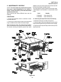
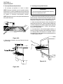
II. MAINTENANCE - MONTHLY
NOTE: The oven interior may require cleaning more
than once a month depending on the volume of
baking. To clean the interior, you have to disassemble
some parts of the oven.
You can order non-caustic cleaner from your local authorized Blodgett Parts Distributor in the quantities listed
below:
Part #
Quantity
When cleaning your Series BE3240 Oven note the
following:
27170-0244
Case of Quarts (6)
PRECAUTIONS-
27170-0246
Case of Gallons (4)
1. Do not use excessive water or saturation of oven
insulation will occur.
A. Removing Conveyor From Oven For Cleaning
1. Remove crumb pans as shown in Figure 4-2.
2. Do not use a caustic oven cleaner or the aluminized
finger manifold surfaces will be severely damaged.
2. Remove upper and lower end plugs from each end of
oven by removing the two wing screws from each end plug.
When cleaning your oven, first remove all heavy debris
with a vacuum cleaner. Use a damp cloth for light cleaning.
For heavier cleaning of baked on grease and carbon
3. Remove the conveyor end stop and the conveyor rear
stop (Figure 4-3).
Figure 4-3.
33
SECTION 4
MAINTENANCE
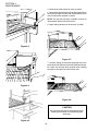
4. Remove conveyor drive chain cover as shown.
5. Remove tension from drive chain by lifting and pushing
the conveyor slightly into the oven. Remove drive chain
from conveyor drive sprocket as shown.
NOTE: The split belt conveyor assembly can only be
removed from the drive end of the oven.
6. Begin sliding conveyor out of the oven as shown.
Figure 4-4.
Figure 4-7.
7. Continue sliding the conveyor completely out of the
oven, fold it in half and then place it to the side for cleaning.
Be careful not to bump drive sprocket while handling
conveyor or damage may result to drive shaft.
Figure 4-5.
Figure 4-8.
CAUTION
Be careful not to bump the drive sprocket while
handling the conveyor, to avoid damaging the
drive shaft.
Figure 4-6.
34
SECTION 4
MAINTENANCE
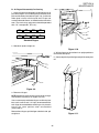
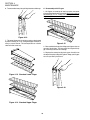
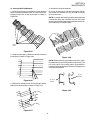
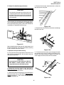
B. Air Fingers Disassembly For Cleaning
1. As the air fingers are removed use a felt pen to mark all
parts of the fingers. This includes the finger manifold, inner
plate and the outer plate (refer to Figure 1-9). If a blank or
choke plate is used, mark that plate also. Fingers are
marked in the order shown; as viewed from the front of the
oven. (The marks for an upper oven should be preceded
with a “U”, example UB1, UT2, etc.)
T1
T2
T3
T4
B1
B2
B3
B4
Standard Fingers
2. Slide blank plates straight out.
Figure 4-10.
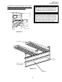
4. With air fingers out, place them in an upright position to
remove the outer plate.
5. Gently step o the lip of the finger and pull the outer plate
off.
Figure 4-9.
3. Remove air fingers.
NOTE: Some oven users require a custom finger arrangement where the quantity of air fingers may vary.
You can remove top and bottom fingers and blank plates
from each or either end. It is highly recommended that
each finger be marked before removing so it is placed in
exactly the same position when reassembled
(refer to step 1).
Remove the air fingers, pull the finger at the back side - pull
straight out.
Figure 4-11.
35
SECTION 4
MAINTENANCE
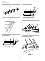
6. To remove the inner plate, pull the plate out and then up.
C. Reassembly of Air Fingers
1. Air fingers are made up of one inner plate, one outer
plate and the finger housing manifold. Be sure to match up
the markings (T1, T2, T3, etc.) on all the parts of the air
fingers as you are reassembling.
Figure 4-12.
7. The outer finger plate is stainless and may be cleaned
by either soaking in a hot, strong detergent solution or
using a caustic cleaner. The conveyor belt can also be
cleaned in the same way.
Figure 4-15.
2. Reassemble the inner plate. Keep your fingers clear so
you won’t pinch them. The inner plate of a finger will only
go in one way because of its design.
3. Replace the outer plate by placing your hands flat on
the top of the plate and pushing down. Keep your fingers
clear so you won’t pinch them.
Figure 4-13. Standard Lower Finger
Figure 4-16.
Figure 4-14. Standard Upper Finger
36
SECTION 4
MAINTENANCE
4. Replace the air fingers by pushing in at the back side.
Remember to replace them according to the numbers
marked on them when they were removed. They must go
back in the same way they came out.
IMPORTANT: Only M6 Fingers fit in the bottom
row. All M3 and M1 finger cover plates have
extended lips at front. This extended lip will not
allow these fingers to be installed in the bottom row.
IMPORTANT: When inserting fingers the tab on
the outer plate must be in the groove as shown in
Figure 4-18. There is a blocking tab on the outside
of the groove which will prevent inserting the
finger in the groove if the outer plate is moved
away from the flange of the finger manifold.
Figure 4-17.
Extended Lip
Tab on
Outer Plate
Flange of
Finger Manifold
Figure 4-18.
Tab on
Outer Plate
37
SECTION 4
MAINTENANCE
5. Install fingers and blank plates correctly with edges
interlocked and no space between edges.
Incorrect - Too
Much Space
Top Finger
Blank Plate
Tab on Outer Plate of Finger
Located in Groove
Incorrect - Too
Much Space
Top Finger
Blank Plate
Tab on Outer Plate of Finger
Located in Groove
Correct Edges Overlap
Completely
Top Finger
Blank Plate
Tab on Outer Plate of Finger
Located in Groove
Figure 4-19.
38
SECTION 4
MAINTENANCE
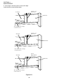
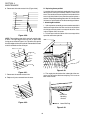
D. Reinstall End Plugs
1. Reinstall lower end plug. Be sure to tighten two wing
screws on the end plug.
2. Reinstall conveyor.
3. Reinstall upper end plug. Be sure to tighten two wing
screws on the end plug.
Figure 4-20.
Figure 4-21.
39
SECTION 4
MAINTENANCE
E. Conveyor Reassembly Into Oven
F. Checking Conveyor Belt Tension
1. Lift conveyor and position it in oven as shown.
WARNING
NOTE: Conveyor assembly may be inserted into either
end of oven. If it is to be installed from the non-drive end
of the oven the drive sprocket assembly must be removed
as shown in conveyor disassembly section.
Oven conveyor belt must be cool when adjusting
belt. Do not adjust belt if HOT.
1. With the conveyor assembly in the oven, stand at one
end of conveyor and check tension by lifting the conveyor
belt at the center of the oven chamber opening. The belt
should not lift higher that 3″ to 4″ (75mm to 102mm).
NOTE: Split belt conveyors can only be inserted from the
drive end of the oven.
2. Adjust conveyor belt tension screws (located on left
end of oven) for the 3″ to 4″ (75mm to 102mm) deflection
as shown in Figure 4-26. If there is proper tension, proceed
to “J. Attaching Drive Chain”. If belt is still too loose,
continue to step 3 below.
3. If conveyor belt is still not under proper tension, an
entire link must be removed. Use the following procedure
“H. Conveyor Belt Link Removal” to remove a link. If
conveyor belt is under proper tension proceed directly to
“J. Attaching Drive Chain”.
Figure 4-22.
2. Reinstall the conveyor rear stop. Reinstall the conveyor end stop.
Figure 4-24.
Figure 4-23.
40
SECTION 4
MAINTENANCE
G. Conveyor Belt Link Removal
4. Unhook the link to be removed.
1. Using long nose pliers, an entire link can be removed
with the conveyor assembly either in or out of the oven.
Position master links at end of conveyor as shown in
Figure 4-25.
5. Pull up on the belt link section and remove. Do not
discard the link removed as it may be used for making
spare master links.
NOTE: If a section of the conveyor belt is being replaced
it should be done now. Remove the links that need
replacing and use the section of conveyor belt furnished in
your installation kit to replace them.
Master
Links
Figure 4-25.
2. Using long nose pliers, unhook master links at left end
of conveyor as shown in Figure 4-26.
Figure 4-28.
NOTE: Before connecting the inside master links, notice
that these links have a correct position (Figure 4-29). The
link at the right is in the correct (horns up) position for
inserting into the conveyor belt. The horns facing down are
in the incorrect position.
Correct
Position
Incorrect
Position
Figure 4-26.
3. Remove the outside master links on the right and left
sides of the conveyor belt as shown in Figure 4-27.
Figure 4-29.
Figure 4-27.
41
SECTION 4
MAINTENANCE
6. Reconnect the inside master links (Figure 4-30.)
H. Replacing Conveyor Belt
If a section of the conveyor belt needs replacing it can be
done with the conveyor assembly either in or out of the
oven. The section of the conveyor belt furnished with the
oven in the installation kit may then be used to replace a
section. Follow the preceding procedure “H. Conveyor belt
link removal” which outlines the disassembly procedure.
I. Attaching Drive Chain
1. If drive sprocket assembly was removed reassemble it
into the conveyor drive shaft. Be sure flat on end of drive
shaft aligns with set screw in conveyor shaft collar. Once
in place tighten 3/32″ set screw.
2. Lift conveyor and install drive chain to conveyor drive
sprocket and motor sprocket.
Figure 4-30.
NOTE: The outside master links have right and left sides
to them. The right edge master link has an open hook
facing you as shown in Figure 4-31. This will match up with
the outer edges of the conveyor belt. Remember this hook
travels backwards on the conveyor.
Direction of travel
Figure 4-33.
Figure 4-31.
3. The angle plate located on the underside of the conveyor must be against the lower end plug. This is true on
both sides of oven.
7. Reconnect the outside master links.
8. Replace all parts removed from the oven.
Crumb Pan
Mounting
Bracket
Figure 4-32.
Lower End Plug
Figure 4-34.
42
SECTION 4
MAINTENANCE
4. Reassemble conveyor drive chain cover and then
reassemble the bottom cover to the drive chain cover.
III. MAINTENANCE - EVERY 3 MONTHS
Install both upper end plugs.
WARNING
Shut OFF all electrical power and lock/tag out the
switch before attempting maintenance work.
Shut OFF gas supply to oven.
NOTE: It is recommended that the 3-month maintenance be performed by an authorized Middleby Marshall
technician.
A. Cleaning the Blower/Fan Motor
To gain access to the blower/fan motor, open the control
cabinet door by removing the three screws. Clean the
motor, burner blower motor, the conveyor drive motor and
the surrounding area, using either compressed air or CO2.
Thoroughly blow out the motor compartment and vents
inside the motor (Figure 4-36). Failure to do this can cause
premature failure of blower fan motor.
Figure 4-35.
CAUTION
Not cleaning the blower/fan motor properly can
cause premature failure.
Figure 4-36.
43
SECTION 4
MAINTENANCE
B. Electrical Terminals
CAUTION
Open the control cabinet door by removing the three
screws from the control cabinet door. Tighten all electrical
control terminal screws including the electrical contactor
terminal screws as shown in Figure 4-37.
Overtightening the belt will cause premature bearing
failure and possible vibration problems. A spare
belt is located inside the control compartment on
the rear wall.
3. When replacing the belt, loosen the tension adjustment
bolts (Figure 4-40) on the motor mounting bracket. Next,
pull back on the motor. Retighten adjustment bolts. Do not
overtighten because the fan bearings may be damaged.
Figure 4-37.
Figure 4-39.
C. Ventilation
Check that the air circulation throughout the oven is not
blocked and is working properly.
D. Checking the Blower/Fan Belt
1. Check the main blower/fan belt for proper tension and
wear. To gain access,loosen the six screws (Figure 4-38)
of the rear shroud and lift shroud cover up and off.
2. The fan belt should deflect no less than 1″ (25mm) at
the center (Figure 4-39) and have no cracks or excessive
wear.
Figure 4-40.
Figure 4-38.
44
SECTION 4
MAINTENANCE
E. Blower Fan Shaft Bearing Lubrication
3. Remove the conveyor adjustment bolts to allow the
idler brackets to swing free.
CAUTION
Over-greasing damages the bearing seals and
accelerates grease loss, which shortens bearing
life. Wipe off any excess grease on and around
the bearing. Reinstall the rear shroud to allow the
oven to operate
Grease the two (2) main blower fan shaft bearings (Figure
4-41), using a special grease (MM P/N 17110-0015 lithiumbase, high-temperature grease). ONLY ONE STROKE of
a grease gun is required for each bearing.
Figure 4-42.
4. Drop the idler shaft assembly clear of the frame through
the front frame slot.
Figure 4-41.
Upon completing the fan belt check (or replacement) and
the bearing lubrication, reinstall the rear shroud, fastening
it with six screws of the rear shroud.
Figure 4-43.
F. Split-belt Conveyor Shaft Cleaning
5. Pull the front and rear shafts apart and apply oil to both
the extended shaft and the interior of the hollow shaft.
Using a rag, wipe oil off parts. Repeat until shafts are
clean. Apply more oil to shafts then reassemble.
It is very important that the split-belt conveyor drive and
idler shafts are removed from the conveyor frame for
cleaning and lubrication.
CAUTION
Use a turbine oil or light machine oil. DO NOT
USE WD40 or similar product. These oils
evaporate and cause the shafts to seize.
1. Perform the conveyor removal steps described in
Monthly Maintenance, paragraph “A”. After the conveyor
is removed, lay it on a flat surface.
2. Remove the two conveyor belts by disassembling the
conveyor master links, as described in Monthly Maintenance, paragraph “H”. Then, remove the two conveyor
belts by rolling them up.
Figure 4-44.
45
SECTION 4
MAINTENANCE
6. Make sure bronze washer is in between the two halves.
9. Loosen the split locking collar.
Figure 4-45.
7. Place the idler shaft assembly back into place and
reinstall the adjustment screws.
Figure 4-48.
10. Remove drive shafts by sliding to right then lifting the
left side. Follow cleaning and lubricating procedures outlined in Steps 4-6.
Figure 4-46.
Figure 4-49.
8. Loosen the set screw on each conveyor drive sprocket
and remove sprockets.
11. Reassemble conveyor drive shafts into frame, making sure nylon spacer is in place.
Figure 4-47.
Figure 4-50.
46
SECTION 4
MAINTENANCE
12. Slide shaft assembly to right side, holding assembly
in place. Slide split locking collar to the left side and
tighten.
13. Slide rear conveyor drive sprocket onto shaft. Tighten
the set screw of this drive sprocket until it extends into the
hole of the hollow shaft. It should NOT touch the inner,
solid shaft. Check to see that only the rear shaft moves
when the sprocket is turned. If both shafts move, you have
tightened the set screw too tight. Loosen the set screw
until only the rear shaft moves when the sprocket is
turning.
Figure 4-51.
14. Insert adaptor bushing into remaining drive sprocket
then place onto shaft. Make sure nylon spacer is in place.
Tighten set screw making sure screw goes through slot in
adaptor bushing and locks onto shaft.
15. Thread conveyor belts back onto frame making sure
the links will be traveling in the proper direction.
16. Follow conveyor reassembly instructions in Monthly
Maintenance Paragraph “F”.
NOTE: It is recommended that the 6 Month Maintenance
schedule be performed by a Blodgett authorized service
technician.
IV. MAINTENANCE - EVERY 6 MONTHS
Figure 4-52.
A. Check brushes on D.C. conveyor motor, when worn to
less than 1/10″ (2.4mm), replace the brushes.
B. Clean and inspect the burner nozzle and electrode
assembly. Also check your oven venting system.
C. Check conveyor shaft bushings and spacers. Replace
them if they are worn. See Figure 6-5, Conveyor Exploded
Drawing, items 15, 30 and 31 or Figure 6-6, Split Belt
Conveyor, items 19, 23, 31, 35 and 36.
IMPORTANT NOTICES:
• Installation of replacement parts requiring access
to the interior of the oven is permitted only by an
authorized service technician.
Figure 4-53.
• If there are any problems with the operation of the
oven, the authorized service technician must be
called.
• It is suggested to obtain a service contract with a
manufacturer’s authorized service technician.
Figure 4-54.
47
SECTION 4
MAINTENANCE
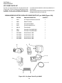
KEY SPARE PARTS KIT
can reduce serious downtime and loss of production, if a
failure occurs.
An oven can be purchased with a Key Spare Parts Kit
(Figure 4-56). (The kit can be purchased when the oven
is ordered, or later, from a Blodgett Authorized Parts
Distributor). The kit contains many of the crucial parts that
Replacement parts for this kit can be purchased from your
Blodgett Authorized Parts Distributor.
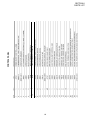
BE3240-SERIES ELECTRIC OVEN KEY SPARE PARTS KIT, p/n 36805 (Figure 4-56)
ITEM
PART NO.
ENGLISH DESCRIPTION
1
47321
Kit, Temperature Control On/Off Pid
1
2
44687
Blower/Fan Motor
1
3
47797
Conveyor Drive Motor
1
4
37337
Conveyor Speed Control
1
5
33812-3
Thermocouple
1
6
44914
Controller, Power 208V/240V
1
6
44568
Controller, Power 380V/480V
1
7
27375-0001
Heater Element, 208V
1
7
27375-0002
Heater Element, 240V
1
7
27375-0003
Heater Element, 380V
1
7
27375-0004
Heater Element, 480V
1
Figure 4-54. Key Spare Parts Kit, p/n 36805
48
QUANTITY
SECTION 5
TROUBLESHOOTING
SECTION 5
TROUBLESHOOTING
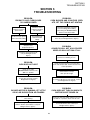
PROBLEM:
OVEN BLOWER AND CONVEYOR OPERATE, YET THE OVEN IS NOT HEATING
PROBLEM:
PRODUCTS ARE OVERCOOKED
OR UNDERCOOKED
Check for correct
setting of conveyor
speed control.
Check for correct
setting on temperature controller.
Reset the temperature controller
to a new setting (above 200°F),
after turning the BLOWER/HEAT
switch to off for 30 seconds.
Set the conveyor speed
control at correct setting.
Turn temperature
control to correct
setting.
Start the oven again. If the oven still does not
heat, call your Blodgett Service Agency.
Verify the food
preparation process.
PROBLEM:
CONVEYOR WILL NOT HOLD PROPER
SPEED OR WILL NOT RUN AT ALL
If products still cook incorrectly,
call your Blodgett Service
Agency.
Check whether the conveyor is
jammed on something in oven.
PROBLEM:
OVEN DOES NOT HEAT
Check for proper tension of conveyor drive
chain and conveyor belt. Refer to Section 4 for
correct procedure.
Check to see if the
BLOWER/HEAT switch is in the
“ON” or “I” position.
Check that the conveyor
drive sprocket is tight.
If oven does not heat, call your
Blodgett Service Agency.
If conveyor still does not run correctly, contact
your Blodgett Service Agency.
PROBLEM:
BLOWER MOTOR IS RUNNING, YET LITTLE
OR NO AIR BLOWS FROM AIR FINGERS
PROBLEM:
OVEN DOES NOT TURN ON WHEN ITS
SWITCHES ARE TURNED ON
Air fingers reassembled incorrectly,
after cleaning.
Check that all electric supply switches are set to
the “ON” or “I” position. Then, start the oven.
Assemble air fingers correctly, after cleaning.
Refer to Section 4 procedure, or call your
Blodgett Service Agency.
If oven still will not start, contact your
Blodgett Service Agency.
49
SECTION 5
TROUBLESHOOTING
NOTES
50
SECTION 6
PARTS LIST
ENGLISH
SECTION 6 - PARTS LIST
51
SECTION 6
PARTS LIST
ENGLISH
52
1
1
16
8
8
8
4
4
4
21
22
23
24
25
26
27
28
4
13
20
4
12
1
1
11
19
1
10
A/R
4
9
18
1
8
A/R
2
7
17
1
6
A/R
16
5
16
8
4
2
8
3
15
2
2
2
2
1
14
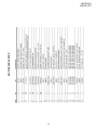
QTY.
ITEM
53
45206
45209
45205
21216-0018
21426-0004
21416-0003
21172-0004
22500-0041
M3540
57399
21416-0001
21422-0001
220373
22290-0010
22290-0009
37900-0102
37900-0024
37900-0025
51054
21256-0008
33486
50637
49905
21296-0005
45449
36452
49946
49947
P/N
QUAD ADJUSTMENT FOOT INSERT
QUAD OUTRIGGER WLDMT
QUAD CASTER SPACER
SCREW, HHCS 1/2-13X1-1/4 18-8
LOCK WASHER 1/2" 18-8
FLAT WASHER 1/2" 18-8
NUT, 3/8-16 NYLON INSULATED L/N ZINC
LABEL “CAUTION HOT SURFACE”
INSTRUCTION LABEL
NAME PLATE BLODGETT
FLAT WASHER, 3/8 ZP
WASHER, LOCK SPLIT 3/8
SCR,HEX HEAD 3/8-16X1 SST
CASTER, SWVL FLAT PLATE
CASTER, SWVL W/BRAKE FLAT PLATE
LEG, 6" H/TOP PLATE WLDMT
LEG/TOP PLATE WLDMT
COMPLETE BASE WLDMT
GLASS DOOR ASSY
SCR, 10-32X3/8 18-8 SL TRUSS
COVER, TOP 304 PANEL
EYEBROW
CONVEYOR CHAIN COVER
SCR, HEX WSHHD12-14X3/4",SS BSD (NOT SHOWN)
END PLUG MOUNTING PLATE ASSY (NOT SHOWN)
WINGNUT, PLASTIC 1/4-20
LOWER END PLUG ASSY
UPPER END PLUG ASSY
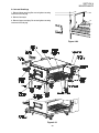
DESCRIPTION
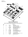
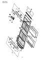
OVEN PANELS, WINDOW AND LEGS
ENGLISH
SECTION 6
PARTS LIST
SECTION 6
PARTS LIST
ENGLISH
54
1
1
7
7A
57423
57603
LABEL, CTRL DOOR RT UPR BE3240
LABEL, CTRL DOOR RT LWR BE3240
CONTROL PANEL
ENGLISH
SECTION 6
PARTS LIST
55
SECTION 6
PARTS LIST
ENGLISH
56
BLOWER AND SHROUD
ENGLISH
SECTION 6
PARTS LIST
57
SECTION 6
PARTS LIST
ENGLISH
58
2
4
1
1
1
15
16
17
18
1
9
14
4
8
1
1
7
13
1
6
1
1
5
12
1
4
1
1
3
11
1
2
1
1
1
10
QTY.
ITEM
59
49400-0013
37900-0071
49400-0072
21176-0002
35900-0398
49400-0074
22151-0003
22151-0002
49400-0050
50265
2001371
33900-0018
33900-0017
33900-0016
51380
33900-0032
22450-0225
47042
P/N
IDLER SIDE ASSEMBLY - CONVEYOR
INCLUDES ITEMS 19, 20, 21, 22 & 23
COMPLETE CONVEYOR FRAME
WELDMENT - IDLER
CONVEYOR FRAME ASSEMBLY - IDLER
INCLUDES ITEMS 17 & 18
LOCKNUT, HEX SS 3/8″-16
PIVOT PLATE - CONVEYOR FRAME
COMPLETE FOLDING CONVEYOR ASSY
INCLUDES ITEMS 14, 15, 16 & 26
SPROCKET, #35-15T-1/2″
SPROCKET, #35-10T-5/8″
ROLLER CHAIN ASSEMBLY, SIB
CONVEYOR CONTROL PICKUP
KIT(NOT SHOWN)
NUT, KEPS 10-32, ZP
MASTER LINK - RIGHT 1/2P × 32″
MASTER LINK - MIDDLE 1/2P × 32″
MASTER LINK - LEFT 1/2P × 32″
KIT, MASTER LINK,
CONTAINS ((1) 33900-0016,
(4) 33900-0017, (1) 33900-0018)
CONVEYOR CHAIN, SS WIRE1 FT
CONVEYOR BELT,
1/2P 32″ × 204″ 2.84/11 S
SINGLE CONVEYOR 80″
EXCLUDES ITEMS 7, 8, 9, 12, 36 & 37
DESCRIPTION
2
2
1
37
38
1
35
36
1
34
1
1
32
33
2
1
1
1
1
31
30
29
28
27
1
12
24
26
1
23
1
2
22
25
2
2
20
21
2
QTY.
19
ITEM
CONVEYOR
47797
35900-0305
35900-0255
35900-0148
35000-1103
35000-1012
49400-0012
35000-1080
35000-1013
22011-0013
49400-0011
37900-0075
49400-0073
35000-1011
22229-0003
49400-0014
37000-0413
35900-0020
35000-1008
22034-0003
P/N
ENGLISH
MOTOR, GEAR 1/50HP 1350:1
CRUMB PAN - CONVEYOR
CRUMB PAN W/SLOTS - CONVEYOR
STOP, BACK SIDE CONVEYOR EXT
STOP, SIDE END CONVEYOR EXT
DRIVE SHAFT - CONVEYOR
DRIVE SHAFT ASSEMBLY
INCLUDES ITEMS 24 & 33
NYLON SPACER 3/4″ ID 1-1/4″ OD
DRIVE SHAFT ADAPTER
SHAFT COLLAR W/SCREW
DRIVE SIDE ASSEMBLY - CONVEYOR
INCLUDES ITEMS 19, 21, 29, 30, 31 & 32
COMPLETE CONVEYOR FRAME
WELDMENT - DRIVE
CONVEYOR FRAME ASSEMBLY - DRIVE
INCLUDES ITEMS 27 & 28
IDLER SHAFT - CONVEYOR
CONVEYOR DRIVE SPROCKET 2.0″ OD
W/SCREW
IDLER SHAFT ASSEMBLY
INCLUDES ITEMS 24 & 25
IDLER WELDMENT
CONVEYOR SHAFT SUPPORT BRACKET
SCREW, ADJ - CONVEYOR IDLER
BUSHING, FLANGE 3/4″ OD, × 5/8″ ID N/D
DESCRIPTION
SECTION 6
PARTS LIST
SECTION 6
PARTS LIST
ENGLISH
60
1
2
4
16
1
1
2
15
16
17
18
19
20
2
9
14
4
8
1
1
7
13
1
6
1
1
5
12
1
4
1
1
3
11
1
2
1
1
1
10
QTY.
ITEM
61
22034-0003
37900-0071
49400-0093
22229-0003
21176-0002
35900-0398
49400-0092
22159-0004
22159-0003
49400-0051
49400-0070
50265
2001371
33900-0018
33900-0017
33900-0016
51382
33900-0037
22450-0226
50646
P/N
BUSHING, FLANGE 3/4″ OD, × 5/8″ ID N/D
COMPLETE CONVEYOR FRAME
WELDMENT - IDLER
CONVEYOR FRAME ASSEMBLY - IDLER
INCLUDES ITEMS 17, 19, 20, 21, 22, 23 & 24
CONVEYOR DRIVE SPROCKET
2.0″ OD W/SCREW
LOCKNUT, HEX SS 3/8″-16
PIVOT PLATE - CONVEYOR FRAME
COMPLETE FOLDING CONVEYOR SPB
ASSY INCLUDES ITEMS 15, 15, 16, 19 & 36
SPROCKET, #25-30T-1/2″
SPROCKET, #25-20T-5/8″
ROLLER CHAIN ASSEMBLY, SPB 26-1/2″
ROLLER CHAIN ASSEMBLY, SPB 15″
CONVEYOR CONTROL PICKUP
KIT(NOT SHOWN)
NUT, KEPS 10-32, ZP
MASTER LINK - RIGHT 1/2P × 32″
MASTER LINK - MIDDLE 1/2P × 32″
MASTER LINK - LEFT 1/2P × 32″
KIT, MASTER LINK,
CONTAINS ((1) 33900-0016,
(1) 33900-0017, (1) 33900-0018)
CONVEYOR CHAIN, SS WIRE1 FT
CONVEYOR BELT, 1/2P
15″ × 146″ 2.86/5 SP
SPLIT CONVEYOR 50/50 80″
EXCLUDES ITEMS 7, 8, 9, 12, 36 & 37
DESCRIPTION
2
2
2
40
41
1
38
39
1
37
1
1
35
36
1
1
1
34
33
32
1
2
30
31
1
1
29
28
1
1
26
27
2
1
24
25
2
2
22
23
2
QTY.
21
ITEM
SPLIT BELT CONVEYOR
47797
35900-0305
35900-0255
35900-0148
35000-1103
37900-0075
35900-0023
49400-0018
35900-0022
35524
35000-1531
35000-1080
22011-0014
49400-0095
42400-0354
35000-1535
21415-0001
35525
37000-0413
35900-0020
35000-1008
P/N
ENGLISH
MOTOR, GEAR 1/50HP 1350:1
CRUMB PAN - CONVEYOR
CRUMB PAN W/SLOTS - CONVEYOR
STOP, BACK SIDE CONVEYOR EXT
STOP, SIDE END CONVEYOR EXT
COMPLETE CONVEYOR FRAMEDRIVE WELDMENT
BUSHING, SPROCKET-FRONT DRIVE
FRONTCONVEYORDRIVESHAFTASSY,SPB
CONN-REAR CONVEYOR DRIVE SHAFT
DRIVE SHAFT ASSEMBLY, SPB
INCLUDES ITEMS 25, 33 & 34
NYLON SPACER
NYLON SPACER 3/4″ ID 1-1/4″ OD
SPLIT-SHAFT COLLAR
CONVEYOR FRAME-DRIVE ASSY, SPB
INCLUDES ITEMS 12, 17, 20, 22, 29, 30,
31, 32, 35 & 36
FRONT CONVEYOR IDLER SHAFT
ASSEMBLY, SPB
REAR CONVEYOR IDLER SHAFT, SPB
FLAT WASHER, BRONZE
IDLER SHAFT ASSEMBLY, SPB
INCLUDES ITEMS 25, 26 & 27
IDLER WELDMENT
CONVEYOR SHAFT SUPPORT BRACKET
SCREW, ADJ - CONVEYOR IDLER
DESCRIPTION
SECTION 6
PARTS LIST
SECTION 6
PARTS LIST
ENGLISH
62
QTY.
1
1
1
1
1
8
8
8
4
4
4
4
1
1
1
ITEM
1
2
3
4
5
6
7
8
9
10
11
12
13
14
63
15
33812-3
31497
36451
A3682
21126-0004
3023A8807
A3896
21416-0001
21422-0001
1513D8805
50449
49953
44687
28021-0061
28021-0047
P/N
THERMOCOUPLE, TYPE “J” SHIELDED 9.50 × 60″
FINGER COOLING FAN GUARD
COOLING FAN 230V AC
LOCK WASHER 5/16″
HEX NUT SS 5/16-18
FLAT WASHER 5/16″ SAE NP
MACHINE SCREW, HEX HD 5/16″-18 × 1″ 18-8
FLAT WASHER SS 3/8″
LOCK WASHER, SPLIT 3/8″ ZP
SCREW, HEX HD 3/8″-16 × 3/4″ - NP
MOTOR SUPPORT BRACKET
MOTOR MOUNTING BRACKET WELDMENT
MOTOR 1/2 HP
MOMENTARY SWITCH - 10A NO 2 POLE
INTERLOCK SWITCH 10A NO2P
DESCRIPTION
MACHINERY COMPARTMENT
ENGLISH
SECTION 6
PARTS LIST
SECTION 6
PARTS LIST
NOTES
ENGLISH
64
SECTION 7
ELECTRICAL SCHEMATICS
Wiring Diagram, E208-240 50/60, 3PH 4W BE3240
SECTION 7
ELECTRICAL SCHEMATICS
65
Wiring Diagram, E380-480 50/60, 3PH 5W BE3240
SECTION 7
ELECTRICAL SCHEMATICS
66
Wiring Diagram, E380V 50/60, 3PH 5W BE3240
SECTION 7
ELECTRICAL SCHEMATICS
67
SECTION 7
ELECTRICAL SCHEMATICS
NOTES
67
WARNING
Improper installation, adjustment, alteration, service or maintenance
can cause property damage, injury or death. Read the installation,
operating and maintenance instructions thoroughly before
installing or servicing this equipment.
NOTICE
During the warranty period, ALL parts replacement and servicing should be performed by
your Blodgett Authorized Service Agent. Service that is performed by parties other
than your Blodgett Authorized Service Agent may void your warranty.
NOTICE
Using any parts other than genuine Blodgett factory manufactured parts relieves the
manufacturer of all warranty and liability.
NOTICE
Blodgett reserves the right to change specifications at any time.
Blodgett is proud to support the Commercial Food Equipment
Service Association (CFESA). We recognize and applaud
CFESA's ongoing efforts to improve the quality of technical
service in the industry.
G.S. Blodgett Corporation • 50 Lakeside Avenue, Box 586 • Burlington, Vermont 05402 • USA
Telephone (800) 331-5842, (802) 860-3700 • Fax: (802) 864-0183
www.blodgettcorp.com