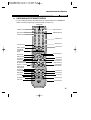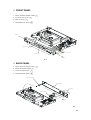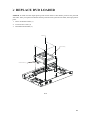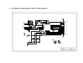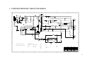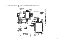
1
SERVICE MANUAL
DVG-8300SE
DVG-5200S
CATALOG
1.SUMMARIZATION
1-1
IMPORTANT SAFETY PRECAUTIONS……………………………………………………………….1-1
FEATURES ……………………………………………………………………………………….1-6
ABOUT MANUAL……………………………………………………………………………………1-7
TERMS FOR DISCS………………………………………………………………………………..1-8
BEFORE OPERATION………………………………………………………………………………1-10
PREPARATIONS BEFORE OPERATION…………………………………………………………….1-12
CONNECTIONS…………………………………………………………………………………….1-16
BASIC OPERATIONS………………………………………………………………………………1-17
PLAYING A DESIRED SCENE……………………………………………………………………..1-21
PLAY DISCS IN VERIOUS WAYS…………………………………………………………………1-25
FUNCTION SETTING………………………………………………………………………………1-30
OTHERS……………………………………………………………………………………………1-36
2.REPLACE PARTS
2-1
REPLACE CHASSIS…………………………………………………………………………….. 2-2
REPLACE PCB BOARD…………………………………………………………………………… 2-4
REPLACE DVD LOADER…………………………………………………………………………..2-7
3.OVERHAUL FLOWCHART
3-1
DECODING BLOCK DIAGRAM……………………………………………………………………..3-2
BLOCK DIAGRAM………………………………………………………………………………… 3-3
CONTROL SCHEMATIC CIRCUIT DIAGRAM……………………………………………………….3-4
POWER SCHEMATIC CIRCUIT DIAGRAM……………………………………………….………..3-5
MTK1369AE INDEX & POWER…………………………………………………..……………… 3-6
MTK1336E SERVO & MT1369AE MFEG DEMO BOARD ..………………………………………..3-7
MEMORY SCHEMATIC CIRCUIT DIAGRAM………………………………………………………..3-8
AUDIO & VIDEO DAC CIRCUIT DIAGRAM……………………………………………………….3-9
AV FILTER SCHEMATIC CIRCUIT DIAGRAM…………………………………………………… 3-10
3-11
KARAOKE SCHEMATIC CIRCUIT DIAGRAM…………………………………………………………
4.IC MATERIAL
4-1
MT1369E IC MATERIAL…………………………………………………………………………. 4-2
CS4340 (AUDIO D/A) IC MATERIAL………..………………………………………………... 4-8
AV 3168 (VIDEO) IC MATERIAL ………………………………………………………………4-9
FLASH 29F080 IC MATERIAL…………………………………………………………………... 4-12
CONTROL PANEL IC MATERIAL………………………………………………………………….4-13
16M SDRAM IC MATERIAL……………………………………………………………………..... 4-14
IMPORTANT SAFETY PRECAUTIONS
CAUTION
RISK OF ELECTRIC SHOCK
DO NOT OPEN
CAUTION: TO REDUCE THE RISK OF ELECTRIC SHOCK,
DO NOT REMOVE COVER (OR BACK). NO USERSERVICEABLE PARTS INSIDE. REFER SERVICING TO
QUALIFIED SERVICE PERSONNEL.
The lightning flash with arrowhead symbol,
within an equilateral triangle, is intended to
alert the user to the presence of uninsulated
“dangerous voltage” within the product’s
enclosure that may be of sufficient magnitude to
constitute a risk of electric shock.
The exclamation point within an equilateral
triangle is intended to alert the user to the
presence of important operating and servicing
instructions in the literature accompanying the
appliance.
WARNING : TO REDUCE THE RISK OF FIRE OR ELECTRIC SHOCK, DO NOT EXPOSE THIS APPLIANCE TO RAIN
OR MOISTURE.
CAUTION : TO PREVENT ELECTRIC SHOCK, MATCH WIDE BLADE OF PLUG TO WIDE SLOT, FULLY INSERT.
IMPORTANT FOR LASER PRODUCTS
• LASER : This Digital Video Disc Player employs a Laser System. To ensure proper use of this
product please read this owner’s manual carefully and retain for future reference. Should
the unit require maintenance, contact an authorized service location - see service
procedure.
Use of control adjustments or the performance of procedures other than those specified
may result in hazardous radiation exposure.
To prevent direct exposure to the laser beam, do not try to open the enclosure. Visible
laser radiation when open and interlocks defeated.
DO NOT STARE INTO THE BEAM.
CLASS 1
• DANGER : Visible laser radiation when open and interlock failed or LASER PRODUCT
defeated. Avoid direct exposure to beam.
• CAUTION : Do not open the top cover. There are no user serviceable parts
inside the Unit; leave all servicing to qualified service personnel.
CAUTION: Any changes or modification in construction of this device which are not
expressly approved by the party responsible for compliance could void the
user’s authority to operate the equipment.
ATTENTION: KEEPING THE STATUS OF STOP IS MORE THAN AN HOUR, THIS SET ENTERS
SCREEN SAVE MODE FOR 5 MINUTES AND THEN THE POWER IS SWITCHED OFF.
MACROVISION
This product incorporates copyright protection technology that is protected by method claims of
certain U.S. patents and other intellectual property rights owned by Macrovision Corporation and
other rights owners. Use of this copyright protection technology must be authorized by Macrovision
Corporation, and is intended for home and other limited viewing uses only unless otherwise
authorized by Macrovision Corporation. Reverse engineering or disassembly is prohibited.
2
IMPORTANT SAFETY PRECAUTIONS
This set has been designed and manufactured to
assure personal safety. Improper use can result
in electric shock or fire hazard. The safeguards
incorporated in this unit will protect you if you
observe the following procedures for
installation, use and servicing. This unit is fully
transistorized and does not contain any parts
that can be repaired by the user.
1 READ INSTRUCTIONS
All the safety and operating instructions
should be read before the unit is operated.
2 RETAIN INSTRUCTIONS
The safety and operating instructions
should be retained for future reference.
3 HEED WARNINGS
All warnings on the unit and in the operating
instructions should be adhered to.
4 FOLLOW INSTRUCTIONS
All operating and use instructions should be
followed.
5 CLEANING
Unplug this unit from the wall outlet before
cleaning. Do not use liquid cleaners or
aerosol cleaners. Use a damp cloth for
cleaning.
6 ATTACHMENTS
Do not use attachments unless
recommended by the unit’s manufacturer as
they may cause hazards.
7 WATER AND MOISTURE
Do not use this unit near water- for example,
near a bath tub, wash bowl, kitchen sink or
laundry tub, in a wet basement, or near a
swimming pool.
PORTABLE CART WARNING
(symbol provided by RETAC)
8 ACCESSORIES
Do not place this
unit on an
unstable cart,
stand, tripod, bracket, or table. The unit
may fall, causing serious injury to a
child or adult as well as serious damage
to the unit. Use this unit only with a cart,
stand , tripod, bracket, or table
recommended by the manufacturer.
8A
A unit and cart combination should be
moved with care. Quick stops, excessive
force, and uneven surfaces may cause the
video product and cart combination to
overturn.
9 VENTILATION
Slots and openings in the case are
provided for ventilation to ensure reliable
operation of the unit and to protect it from
overheating. These openings must not be
blocked or covered. These openings must
not be blocked by placing the unit on a
bed, sofa, rug, or other similar surface.
This unit should never be placed near or
over a radiator or heat radiator. This unit
should not be placed in a built-in
installation such as a bookcase or rack
unless proper ventilation is provided or the
manufacturer’s instructions have been
adhered to.
10 POWER SOURCES
This unit should be operated only from the
type of power source indicated on the
marking label. If you are not sure of the
type of power supply to your home, consult
3
IMPORTANT SAFETY PRECAUTIONS
your video dealer or local power company.
For units intended to operate from battery
power, or other sources, refer to the
operating instructions.
14 DISC TRAY
Keep your fingers well clear of the disc as
it is closing. It may cause serious personal
injury.
11 GROUNDING OR POLARIZATION
This unit is equipped with a polarized
alternating -current line plug (a plug
having one blade wider than the other).
This plug will fit into the power outlet only
one way.
This is a safety feature. If you are unable to
insert the plug fully into the outlet, try
reversing the plug. If the plug still fails to
fit, contact your electrician to replace your
obsolete outlet.To prevent electric shock,
do not use this polarized plug with an
extension cord, receptacle, or other outlet
unless the blades can be fully inserted
without blade exposure. If you need an
extension cord, use a polarized cord.
15 OVERLOADING
Do not overload wall outlets of extension
cords as this can result in a risk of fire or
electric shock.
12 POWER-CORD PROTECTION
Power-supply cords should be routed so
that they are not likely to be walked on or
pinched by items placed upon or against
them, paying particular attention to cords
at plugs, convenience receptacles, and the
point where they exit from the unit.
13 LIGHTNING
For added protection for this unit during a
lightning storm, or when it is left
unattended and unused for long periods of
time, unplug it from the wall outlet and
disconnect the antenna or cable system.
This will prevent damage to the unit due to
lightning and power line surges.
4
16 OBJECT AND LIQUID ENTRY
Never push objects of any kind into this
unit through openings as they may touch
dangerous voltage points or “short-out”
parts that could result in a fire or electric
shock. Never spill liquid of any kind on the
unit.
17 BURDEN
Do not place a heavy object on or step on
the product. The object may fall, causing
serious personal injury and serious
damage to the product.
18 DISC
Do not use a cracked, deformed or
repaired disc. These discs are easily broken
and may cause serious personal injury and
product malfunction.
19 SERVICING
Do not attempt to service this unit yourself
as opening or removing covers may expose
you to dangerous voltage or other hazards.
Refer all servicing to qualified service
personnel.
IMPORTANT SAFETY PRECAUTIONS
20 DAMAGE REQUIRING SERVICE
Unplug this unit from the wall outlet and
refer servicing to qualified service
personnel under the following conditions.
A. When the power-supply cord or plug is
damaged.
B. If liquid has been spilled, or objects
have fallen into the unit.
C. If the unit has been exposed to rain or
water.
D. If the unit does not operate normally
by
following
the
operating
instructions.
Adjust only those
controls that are covered by the
operating instructions. Improper
adjustment of other controls may
result in damage and will often
require extensive work by a qualified
technician to restore the unit to its
normal operation.
E. If the product has been dropped or the
cabinet has been damaged.
F. When the unit exhibits a distinct
change in performance-this indicates a
need for service.
21 REPLACEMENT PARTS
When replacement parts are required,
have the service technician verify that the
replacements he uses have the same
safety characteristics as the original parts.
Use of replacements specified by the unit
manufacturer can prevent fire, electric
shock, or other hazards.
22 SAFETY CHECK
Upon completion of any service or repairs
to this unit, ask the service technician to
perform safety checks recommended by
the manufacturer to determine that the
unit is in safe operating condition.
23 WALL OR CEILING MOUNTING
The product should be mounted to a wall
or ceiling only as recommended by the
manufacturer.
24 HEAT
The product should be situated away from
heat sources such as radiators, heat
registers, stoves, or other products
(including amplifiers) that produce heat.
FCC NOTICE :
This equipment has been tested and found to
comply with the limits for a Class B digital
device, pursuant to part 15 of the FCC Rule.
These limits are designed to provide reasonable
protection against harmful interference in a
residential installation. This equipment
generates, uses and can radiate radio frequency
energy and if not installed and used in
accordance with the instructions, may cause
harmful interference to radio communications.
However, there is no guarantee that
interference will not occur in a particular
installation. If this equipment does cause
harmful interference to radio or television
reception; which can be determined by turning
the equipment off and on, the user is
encouraged to try to correct the interference by
one or more of the following measures:
• Reorientate or relocate the receiving antenna.
• Increase the separation between the
equipment and receiver.
• Connect the equipment to an outlet on a
circuit different from that to which the
receiver is connected.
• Consult the dealer or an experience radio/TV
technical for help.
5
FEATURES
OUTSTANDING SOUND QUALITY
Dolby Digital
system developed by Dolby Laboratories and DTS
developed by DTS Inc., features high quality surround sound, can be played in
DVD or CD disc at home, to reproduce high quality sound effects.
HIGH DEFINITION
The unit adopts MPEG2 coding format and brings the high horizontal
resolution.
UNIQUE FUNCTIONS
Multi-angle and multi-language bring unique trick functions.
Parent lock makes it easy to control the content of discs.
SCREEN
Ordinary screen and wide screen (16:9) are available.
COMPATIBILITY
The unit can play DVD discs, and is compatible with CD, CD-R, CD-RW, PIC-CD
and MP3 discs.
ZOOM
It can enlarge pictures or reduce pictures.
MULTI-FUNCTIONS
Fast forward, fast reverse, forward and reverse slow, frame play , repeat play
and program play.
TIME SEARCH
It can search a specific part on a disc, especially good for watching fiction
movies.
RESUME PLAY
It can memorize the position where the disc is stopped and resume playback.
VIDEO OUTPUT
Standard video, S-video signal output mode, component video output mode.
AUDIO OUTPUT
Analog audio output, coaxial and optical digital audio output, can be
connected with the appropriate amplifier to enjoy high-quality sound effects.
KARAOKE
Microphone input, KARAOKE channel selection.
6
ABOUT MANUAL
PRINCIPLES FOR WRITING
This manual mainly introduces how to use buttons on the remote control.
You may operate the unit if the buttons on the unit have the same or similar
names as or to those on the remote control.
PLAYABLE DISCS
• DVD and Audio CD
Disc type
DVD
CD
CD-G
CD-ROM
CD-R
CD-RW
DVD-R
DVD-ROM
DVD-RAM
DVD+RW
DVD-RW
Photo CD
Playable
Possible
Possible
Possible
Possible
Possible
Possible
Possible
Impossible
Impossible
Possible
Possible
Impossible
Restriction
Region number 4 or Region number All
PCM or dts
Only Audio playback
MP3 File
CD/CD-ROM (MP3 File)
CD/CD-ROM (MP3 File)
DVD Video
DVD Video
DVD Video
DVD Video
7
TERMS FOR DISCS
TITLE
The images or music of a DVD are divided into some units, among which
title is the biggest one.
When playing a DVD, the movie is the title.
When playing a CD, the combined tracks make up the title.
CHAPTER
It is smaller than title among the units of a DVD. A title is made up
of several chapters , and each chapter has a number for search. But
some discs may not have numbered chapters.
TRACK
In a CD, each track has a number to enable search functions.
STRUCTURE OF DVD
STRUCTURE OF CD
DISC
TITLE
CHAPTER
8
DISC
TRACK
TERMS FOR DISCS
SCENE
The menu pictures, motion and motionless pictures of a CD or something discs
with PBC function can be divided into some parts, these parts are scenes. Each
scene has a number for search.
PBC (PLAYBACK CONTROL)
It is signals recorded in a CD or something discs to control playback.
DISC TYPE
disc
without PBC
disc with PBC
FUNCTION
enjoy music and images (motion
pictures)
Besides the images of special disc, play interactive
software with the menu pictures shown on the TV
screen (PBC play). If the disc has motionless
pictures, high-resolution playback is also available.
REGION MANAGEMENT INFORMATION
This unit is designed and manufactured to respond to the Region
Management information that is recorded on a DVD disc. The region
number of this player is “4”. If the region number described on the DVD
discs does not correspond to the Region number of this player, the
player will not play this disc. This player will play DVD discs made for
“ALL” regions. Therefore, this player will play DVD discs marked with
labels containing the region number “4” or “ALL”.
4
(Region 4)
(Region ALL)
9
BEFORE OPERATION
SECURITY
• Before operation, check if the voltage of the unit is in line with the local voltage.
• Hold the plug to disconnect it from the mains outlet. Do not pull the power cord.
• When the plug of the unit is connected to the mains outlet , the unit will be still
connected to AC even if the power is turned off.
• Disconnect the plug as soon as liquid or objects enter the unit. The unit can not
be used until being checked by experts.
• Do not open the cabinet as laser rays employed by the unit may damage eyes.
Any servicing should be done by qualified service personnel.
PLACEMENT
• Put the unit where ventilation is good enough to prevent overheating.
• Never put the unit in direct sunlight or near heat sources.
• Put the unit horizontally, never put any heavy object on the unit.
• To protect the pickup, do not put the unit where there is dust. If there is dust
on the pickup, use a cleaning disc to clean it. Paying particular attention to the
operating instructions of the cleaning disc.
CONDENSATION
Moisture will appear on the pickup lens in the following cases:
• The unit is suddenly moved from a cold place to a warm place.
• The unit is put in a room with a heater, or in cold air from an air-conditioner.
• Using the unit in a humid place. In these cases, the unit can not work. Unload the
disc and leave the unit on for about one hour to evaporate the moisture.
CLEANING
• Use a soft cloth with a little neutral detergent to wipe the cabinet, panel and
controls.
Never use abrasive paper, polishing powder, solvent like alcohol or gasoline.
10
BEFORE OPERATION
HANDLING DISC
• To keep the disc clean, do not touch the playsides of the disc.
• Do not attach paper or tape to the disc.
• Keep the disc away from direct sunlight or heat sources.
• Store the disc in a disc case after playback.
CLEANING DISC
• Before playback, wipe the disc outwards from the centre with clean cloth.
• Do not use any type of solvent such as thinner, benzine, commercially
available cleaners or antistatic spray.
CHECK ACCESSORIES
Check if you have all the accessories after the carton is opened.
Remote control
AAA batteries
Video/Audio cord
Owner’s manual
USE REMOTE CONTROL
-4
M
-U
+
Check if you have all the accessories after the carton is opened.
1. Open the battery compartment.
2. Insert two AAA batteries, make sure to match "+" and "-" of the batteries
to the marks in the battery compartment.
3. Close the battery compartment.
4. Point the remote control at the remote sensor.
N ote:
1. Batteries can last for about 6 months generally. Change the batteries of that does not work.
2. If the remote control is not used for a long time, remove the batteries to prevent battery
leakage.
11
PREPARATIONS BEFORE OPERATION
FRONT PANEL
!
@
#
$
% ^& * () 12
! STANDBY/ON button
To switch the unit On or Off when connected to AC power outlet
@ Microphone Level adjustment knob.
# Microphone Jack
$ TRAY DOOR
Press OPEN/CLOSE button to open it.
% OPEN/CLOSE button
To open or close the disc tray.
^ Remote Sensor
& PLAY button
To play the loaded disc. Press this button to go to the preferred item when
the menu is displayed on the TV screen.
* PAUSE
Press this button in playback mode, the picture stops. This machine enters
the playback pause mode.
( STOP
) One Chapter/Track backward button
To skip back from the status.
1 One Chapter/Track forward button
To skip forward to the status. If playing a disc with PBC, this button works as
the NEXT button to move to the next play list.
2 DISPLAY
Displays operation status
12
PREPARATIONS BEFORE OPERATION
REAR PANEL
! @
L
%
Pr
VIDEO OUT Y
S-VIDEO Pb
OUT
R
OPTICAL
$
#
AUDIO
COMPONENT VIDEO COAXIAL
^
&
! AUDIO OUT (L/R TRACK)
Two phono sockets for analogue 2 Channel audio in order to a TV or stereo
amplifier.
@ VIDEO OUT
Connects composite video signal to input AV or PHONO sockets of TV or
monitor to achieve high fidelity colour reproduction.
# COMPONENT(Y.Pb.Pr)
Connects to TV or monitor equipped with Component input . In order to
achieve a sharper and cleaner picture than that when connected via VIDEO
OUT (composite video).
$ POWER SUPPLY SOCKET WIRE
Creates POWER between wall outlet and the unit.
% DIGITAL AUDIO OPTICAL OUT
Connects digital audio under play mode into an AV amplifier or a receiver
equipped with digital audio decoder for you to enjoy the theater-quality
sound in your home.
^ S-VIDEO OUTPUT
Connects to TV or monitor equipped with S-VIDEO input. In order to achieve
a sharper and cleaner picture than that when connected via VIDEO OUT
(composite video).
& DIGITAL AUDIO COAXIAL OUT
Connects digital audio under play mode into an AV amplifier or a receiver
equipped with digital audio decoder for you to enjoy the theater-quality
sound in your home.
13
PREPARATIONS BEFORE OPERATION
VFD
@
!
#
CD
$
D
% ^
PBC
ALL
& * (
! Recognized DISC TYPE indicator
Illuminates the current operation mode.
@ DVD AUDIO STREAM indicator
Indicates the audio type of the disc under
play is DTS
# Recognized DISC TYPE indicator
CD.
$ DVD AUDIO STREAM indicator
Indicates the audio type of the disc under
play is DOLBY DIGITAL.
% PBC indicator
This indicator is lit up in selecting PBC ON
while this indicator disappears in selecting
PBC OFF.
^ Recognized DISC TYPE indicator
Illuminates when MP3 disc is played.
& DISC LOAD/PLAY indicator
This indicator is lit up after recognizing disc.
* PLAY/ PAUSE indicator
14
)
( REPEAT MODE indicator
: In case you want to repeat and play
a chapter or track.
ALL
: In case you want to repeat and
play a title or disc.
) NUMBER/ CHARACTER indicator
Title, chapter number, and time are
displayed in loading DVD disc while track
number and time are displayed in loading
CD/CDMA/MP3/something disc.
Tray is opened
Tray is closed
Disc is loaded
There is no disc in tray
Disc has some error
PREPARATIONS BEFORE OPERATION
NAMES AND LAYOUT OF REMOTE CONTROLS
* In case of setting the mode by using SETUP menu (for example, AUDIO select in PREFERENCE
SETUP), the setting is kept though you switch the unit off and turn it on.
MUTE BUTTON
POWER BUTTON
OPEN/CLOSE BUTTON
SETUP BUTTON
SURROUND BUTTON
ANGLE BUTTON
NUMBER BUTTON
TITLE/PBC BUTTON
DISPLAY BUTTON
RETURN BUTTON
MENU BUTTON
UP/DOWN/LEFT/
RIGHT DIRECTION
BUTTON
MARK BUTTON
SEARCH BUTTON
PAUSE BUTTON
STEP BUTTON
ONE CHAPTER/TRACK
BACKWARD BUTTON
VOLUME “+/-” BUTTON
FAST BACKWARD
SERACH BUTTON
AUDIO BUTTON
SUBTITLE BUTTON
REPEAT BUTTON
A-B BUTTON
LOWER TONE
CHANNEL BUTTON
ATONIC TONE
PLAY/ENTER BUTTON
PROGRAM BUTTON
ZOOM BUTTON
STOP BUTTON
ONE CHAPTER/TRACK
FORWARD BUTTON
FAST FORWARD
SERACH BUTTON
SLOW BUTTON
INTRO BUTTON
RAISE TONE
SYSTEM BUTTON
V-MODE BUTTON
15
CONNECTIONS
Turn off all equipment before operation.
The unit has many kinds of output modes like A/V output, S-VIDEO output and
digital signal output (COAXIAL, OPTICAL). You may select as you need.
CONNECTED TO A TV AND AN ORDINARY AMPLIFIER
L
VIDEO OUT Y
OPTICAL
Pr
S-VIDEO Pb
OUT
R
AUDIO
COMPONENT VIDEO COAXIAL
WOOFER
OUT
VIDEO
R SURROUND L
Pb
Pr
DVD
IN
MONITOR
OUT
DVD WOOFER
CENTER
IN
CD
COAXIAL IN OPTICAL
Manufactured under license from Dolby Laboratories. "Dolby" and the
double-D symbol are trademarks of Dolby Laboratories. Confidential
Unpublished works.
©1992-1997 Dolby Laboratories, Inc. All rights reserved.
"DTS" and "DTS Digital Out" are trademarks of Digital Theater
Systems, Inc.
16
BASIC OPERATIONS
PLAY DISCS
1
Push "POWER" button on the TV and audio
system, Push "TV/VIDEO" button on the TV,
select VIDEO mode (TV).
Select S-Video mode if using an S-VIDEO
connection.
N ote:
The Step2 can be
cancelled if you
do not
connect it to the
amplifier.
2
3
4
Select the right audio input on the amplifier.
• Each amplifier is different from another,
please refer to the manual of the amplifier.
(e.g., connect the audio output of the DVD
player to the DVD audio input of an amplifier.)
Push "STAND BY/ON" button on the front panel or "
the remote control to turn the unit on.
TV/VIDEO
DVD/LD
" button on
Push "OPEN/CLOSE " button to open the disc tray and insert the
disc with its label look upward. Push "OPEN/CLOSE " button
again to close the disc tray. The unit begins to read the disc. The TV
screen shows the DVD menu and title menu.
• In the case of DVD, DVD menus and titles are displayed on TV
screen.
• In the case of something disc, the menus are displayed on TV
screen and it is converted into PBC (Play Back Control) mode.
• In the case of CD, the disc plays in order of its track number.
5
Stop playback.
Press .
6
Press
to remove the disc.
17
BASIC OPERATIONS
SYSTEM SETTING
According to the system of the TV to be connected, set the system of the unit to
make it match the TV.
Push SYSTEM button on the remote control, then choose TV TYPE.
• If the system of the TV is PAL, push "SYSTEM" once.
• If the TV is multi-system, push "SYSTEM" twice.
• If the system of the TV is NTSC, push "SYSTEM" three
times.
SYSTEM
If the TV has component input, please connect the unit and the TV with
component cord (not supplied).
V-MODE
• In case of connecting the component, press the V-MODE
on the remote control to select YUV (Y, Pb, Pr).
• When you connect the Composite or S-VIDEO and picture
is not displayed, press the V-MODE on the remote control
to check if DVD player position in the video mode.
V-MODE
DISPLAY
Each time you press “DISPLAY” button when playing a disc, the TV screen
shows the information as :
DISPLAY
DVD
• TITLE ELAPSED -> TITLE REMAIN -> CHAPTER ELAPSED
-> CHAPTER REMAIN -> (NOTHING DISPLAY)
TITLE ** / ** CHAPTER ** / ** **: ** : **
CD
• SINGLE ELAPSED -> SINGLE REMAIN -> TOTAL ELAPSED -> TOTAL REMAIN
MP3
• SINGLE ELAPSED -> SINGLE REMAIN -> DISPLAY OFF
Something disc
• SINGLE ELAPSED -> SINGLE REMAIN -> (NOTHING DISPLAY)
TRACK ** / **
18
**: ** : **
BASIC OPERATIONS
FAST PLAY
When playing disc, you may play it forward fast or reverse it fast to find what you need.
N ote:
Push PLAY to play
normally when
playing fast.
1
Push
to play forward fast. Each
time you push the button, the speed of
picture changes like the right sides.
N ote:
The marked FAST
PLAY speed on
owner’s manual
and real fast play
speed can be
different
depending on
which disc you
play.
1
X2
2
X4
3
X8
4
X16
5
X32 (DVD only)
6
2
Push
to reverse the disc fast.
Each time you push the button, the
speed of picture changes like the
right sides.
PLAY
1
X2
2
X4
3
X8
4
X16
5
X32 (DVD only)
6
PLAY
SLOW PLAY
Enjoy slow motions by the following steps.
N ote:
Push PLAY to play
normally .
Push "SLOW" button to play slowly.
• something disc
SLOW
• DVD
N ote:
Push PLAY to play
normally .
STEP/ PAUSE
Push PAUSE
pause.
Pushing STEP
or STEP
on the remote control to make the playback
again moves the picture forward frame by frame.
19
BASIC OPERATIONS
SELECT AUDIO LANGUAGE
You can choose the language according to your choice when playing mulitlanguage DVD.
Press “AUDIO” button, select different languages.
N ote:
AUDIO
1. Different disc has different languages
2. You can push "AUDIO" button to choose the language you want
when you play multi-language DVD discs.
*Attention:
*A
Please select the AUDIO language in SETUP menu to keep the setting!!!
SELECT CHANNELS
You may select the right channel or left channel or stereo from a multi-channel.
Push "CHANNEL" button, the screen show alternately and select the desired
audio channel:
CHANNEL
MONO
LEFT
MONO
RIGHT
MIXMONO
STEREO
N ote:
You can use channel function when you play the disc, you can choose
mono audio output ( left or right channel ), stereo or mix-mono
SELECTING 3D AUDIO
This function outputs 3D effects on the stereo audio analog output where 3D
effects are broken down into 6 surround modes.
1
2
20
Press [3D] button.
Every time the user presses [3D] button,
CONCERT, LIVING ROOM, HALL,
BATHROOM, CAVE, ARENA and CHURCH
appear one by one.
Select the desired 3D sound mode.
REVERB: CONCERT
3D
PLAYING A DESIRED SCENE
TO SKIP SCENES IN A DISC
1
2
Push
to move to next chapter (or track).
The current chapter (or track) moves to the next chapter (or track).
Push
to move to previous chapter (or track).
The current chapter (or track) moves to the previous chapter (or track)
or first scene of current chapter (or track).
DIRECTLY MOVING TO A DESIRED TITLE (DVD)
Some movie discs may contain multiple titles. If the disc has a movie title menu
recorded on it, the [TITLE/PBC] button can be used to select the movie title.
Details of operation may differ depending on the disc used.
1
N ote:
You can select
the desired title
directly by using
number button.
Push the [TITLE/PBC] or [MENU]
button.
A list of the titles on the disc is
displayed.
For the case of something disc, menu
screen will appear only when the disc
has PBC function and PBC ON is
activated.
PLAY MOVIE
SETUP
SCENE SELECTION
SPECIAL FEATURES
* In case of PBC play, press RETURN to return to the sub-menu, press
it again to return to the home menu.
2
Push the [PLAY] button after pressing the [
select the desired title.
] button to
The selected title now starts playing.
21
PLAYING A DESIRED SCENE
PLAYING A DISC CONTAINING MP3 FILES
1
When a MP3 disc is loaded, MP3 menu screen is displayed
automatically depending on MP3 disc’s folder structure.
2
Use the direction button to select the folder you want to play, by
pressing [PLAY] button. This button allows you to see the file lists
under the folder.
3
Use the direction button and select a MP3 title using the PLAY button
then play will start automatically. When you know the title number,
enter the MP3 title number using the numeric buttons on the remote
control and then press [PLAY] button.
4
Press
on the remote control to choose next title.
Press
for previous title. When you know the title number, enter
MP3 title number using the numeric buttons on the remote control and
then press [PLAY] button.
REPEAT PLAY
When play DVD disc, this function can be used to repeatedly play a title, chapter
or disc.
Push "REPEAT" button, the screen shows orderly.
N ote:
Push REPEAT to
cancel the repeat
function.
REPEAT
• DVD
CHAPTER
TITLE
ALL
(NOTHING DISPLAY)
• CD/ something disc
TRACK
ALL
(NOTHING DISPLAY)
• MP3
SINGLE
REPEAT ONE
FOLDER
22
RPT. FOLDER
SHUFFLE
PLAYING A DESIRED SCENE
REPEATING A DEFINED PERIOD FROM A TO B
You may press A-B to enjoy some parts repeatedly when playing a disc.
1. Press “A-B” to set a starting point A.
2. Press “A-B” twice to an end point B.
Afterwards, the unit plays from A to B.
3. Press “A-B” three times to remove A-B repeat.
A-B
A-
A-B
(NOTHING DISPLAY)
SEARCHING DVD WITH A TITLE/CHAPTER NUMBER OR A TIME
You may directly enter a time, title or chapter number to search fast on a disc.
The unit plays from the point.
1
If you want to search with a chapter
and a title number, press [SEARCH]
button one time.
It shows total title numbers and chapter
numbers. Please enter the new chapter
and title number to be searched using
the [NUMBER] buttons.
2
If you want to search with a time in a
title, press [SEARCH] button twice.
Please enter the new time to be searched
using the [NUMBER] buttons.
TITLE 06/09 TIME
3
If you want to search with a time in a
chapter, press [SEARCH] button three
times.
Please enter the new time to be searched
using the [NUMBER] buttons.
CHAPTER 03/04 TIME : :
4
TITLE 03/09 CHAPTER
/04
: :
In completing entering, please press [PLAY] button.
PLAY starts from the selected position.
23
PLAYING A DESIRED SCENE
SEARCHING CD AND SOMETHING DISC WITH A TIME OR TRACK TIME
You may directly enter a disc or track time to search fast on a disc. The unit plays
from the point.
1
If you want to search with a disc
time, press [SEARCH] button one
time.
Please enter the new time to be searched
using the [NUMBER] buttons.
2
If you want to search with a track time
of CD, press [SEARCH] button twice.
Please enter the new time to be searched
using the [NUMBER] buttons.
3
If you want to search with a track
number, press [SEARCH] button until the
picture is displayed in the right side.
It shows total track numbers. Please
enter the new track number to be
searched using the [NUMBER] buttons.
DISC GOTO : - - : - -
TRACK GOTO : - - : - -
SELECT TRACK : - - /05
SELECT A SUBTITLE LANGUAGE
When play a multi-subtitle DVD, you may select one subtitle to show it on the
screen.
N ote:
1. For some discs,
subtitles cannot
be removed.
2. Subtitle
function is only
available for
some discs with
subtitle
recorders.
24
1
2
Keep pressing [SUBTITLE] button till
the user’s preferred language
appears.
If a DVD disc includes subtitle
information, every time the user presses
[SUBTITLE] button, ENGLISH, FRENCH,
SPANISH and others appear one by one.
SUBTITLE 01/03:ENGLISH
SUBTITLE
Remove the subtitle.
Press SUBTITLE until the screen shows "SUBTITLE OFF".
PLAY DISCS IN VERIOUS WAYS
SELECT ANGLE
N ote:
Multi Angle
function is limited
to a DVD disc
supporting multi
angle information.
Some discs have images with different screen angles, you may select among
them. For example, when you watch a running train, you may select to watch it
from the front, the left window or the right window without stopping it.
Keep pressing [ANGLE] button till the
preferred angle appears.
1/4
2/4 (select ANGLE2)
ANGLE
3/4 (select ANGLE3)
4/4 (select ANGLE4)
ZOOM PLAY
This function can be used to enjoy a motion or motionless picture.
1
Push "ZOOM" button when playing, the
screen shows orderly:
1
2
ZOOM
PLAY
3
4
2
5
Push "UP/DOWN/LEFT/RIGHT [
button to move the enlarged picture.
]
6
X2
X3
X4
X1/2
X1/3
X1/4
BOOK MARK
N ote:
If you erase a
book mark
function, push
“RETURN”
button.
1
Push MARK button , the screen will
show the following frame:
2
Moving direction button to select the saving position on the screen.
Push PLAY button to save the time tag.
3
Push MARK button when you need book mark function, then choose
the item you want to resume playing, then push PLAY
button to continue playing from the saving point.
02
08
05
25
PLAY DISCS IN VERIOUS WAYS
PROGRAM PLAY (DVD)
You may program the title and chapter on a disc and play them in the
programmed order.
1
Push "PROGRAM" button, the screen
shows:
PROGRAM
PROGRAM:TT(05) / CH (- -)
01
02
03
04
05
TT:
TT:
TT:
TT:
TT:
CH
CH
CH
CH
CH
06
07
08
09
10
TT:
TT:
TT:
TT:
TT:
EXIT
N ote:
First one is title,
second one is
chapter.
2
Input the sequence number you want to
program playing.
CH
CH
CH
CH
CH
NEXT
PROGRAM:TT(12) / CH (- -)
01
02
03
04
05
TT: 03 CH:01
TT: 08 CH:02
TT: CH
TT: CH
TT: CH
06
07
08
09
10
TT:
TT:
TT:
TT:
TT:
CH
CH
CH
CH
CH
3
After the programming is finished, push
direction button to select "START", Push
"PLAY" button to start playing.
4
Push "PROGRAM" button to remove program play in stop status.
EXIT START
NEXT
* If you erase a program, put the cursor in the position of the
program, push “RETURN” button.
PROGRAM PLAY (CD)
You may program the track on a disc and play them in the programmed
order. (For MP3 play, refer to the page 28 )
26
1
Push "PROGRAM" button, the screen
shows:
2
Push direction button, input the
sequence number you want to program
playing.
After the programming is finished, push
direction button to select "START", Push
"PLAY" button to start playing.
PROGRAM:TRACK (01-10)
01
02
03
04
05
__
__
__
__
__
06
07
08
09
10
EXIT
__
__
__
__
__
NEXT
PLAY DISCS IN VERIOUS WAYS
DIGEST PLAY (DVD)
1
Push "INTRO" button when the unit is
playing disc, the screen shows :
2
Push direction button to select the
digest type.
SELECT DIGEST TYPE :
TITLE DIGEST
CHAPTER DIGEST
TITLE INTERVAL
CHAPTER INTERVAL
INTRO
N ote:
• TITLE DIGEST
The player will play 5 seconds each title. After moving the cursor in the position “--”, push
NUMBER button to select the title and push PLAY button. Then the player will begin to play from
the title you selected. Or put the cursor in the position of desired picture and push PLAY button.
• CHAPTER DIGEST
The player will display the beginning picture of each chapter in current selected title.
• TITLE INTERVAL
Scan the story in the disc from 00: 00 :00 on, the unit will play the disc every other 10 minutes.
• CHAPTER INTERVAL
Scan the story in the current title from 00: 00 :00 on, the unit will play the disc every other 10 minutes.
DIGEST PLAY (something disc)
1
2
Push "INTRO" button when the unit is
playing disc, the screen shows :
Push direction button to select the
digest type.
SELECT DIGEST TYPE :
TRACK DIGEST
DISC INTERVAL
INTRO
N ote:
• TRACK DIGEST
The player will play 5 seconds each track. Push NUMBER button to select the track, then push
PLAY button, the player will begin to play from the track you selected.
• DISC INTERVAL
Scan the story in the disc from 00: 00 :00 on, the unit will play the disc every other 10 minutes.
DIGEST PLAY (CD)
1
2
Push "INTRO" button when the unit is
playing disc, the screen shows :
SCAN
TRACK 01/10
00:05
The player will play 5 seconds each
track.
27
PLAY DISCS IN VERIOUS WAYS
PLAY MP3 OR PIC-CD DISC
USE NUMBER BUTTONS TO SELECT TRACKS (MP3 OR PIC-CD)
1
The screen will display as right after the
disc is loaded
2
Each time you press PROGRAM button,
NORMAL MODE, PROGRAM LIST and
FILE LIST appear one by one.
At this time you can operate the
Program play of the item in the program
list.
3
You can scan all the directors on the
disc by using direction button. You can
play the directory you selected by the
number button. The screen will display
as below if the selected directory has
songs which can be played.
MENU
Cd 01
1
Cd 02
2
Cd 03
3
Cd 04
4
Cd 05
5
Cd 06
6
PLAY MODE
FOLDER
MENU
<UP DIR>
PLAY MODE
Mp3 TRACK 01
Mp3 TRACK 02
Mp3 TRACK 03
Mp3 TRACK 04
FOLDER
Note:
If the number of directory or songs is over 6, you can
use four directions button to select the item you prefer.
You also can use "NEXT" button or "PREVIOUS" button
to change the page number.
4
28
In the above status, you can use "LEFT" button or "DOWN" button to
select the playing area, then push "UP" button or "DOWN" button to
select the item you want to play.
1
2
3
4
PLAY DISCS IN VERIOUS WAYS
SELECT PLAYING MODE (MP3 OR PIC-CD)
1
Push direction button to select the play mode area under stop status,
then push direction button to select different play mode. These play
modes list as the following :
• Single mode: the player will stop after finished playing the current item
• Repeat one mode: repeat the current item
• Repeat folder mode: repeat the items in the current directory
• Shuffle mode: play items by random
• Folder mode: the player will stop after finished playing the whole
directory
2
When playing, push "REPEAT" button, you can select "SINGLE",
"REPEAT ONE", "REPEAT FOLDER" and "FOLDER".
PLAY PIC-CD BY ZOOM OR ROTATING OPERATING (PIC-CD)
The screen will show "ZOOM 100% " when you push ZOOM button under
playing status, the current picture can be zoomed by push
or
button,
and the screen will also show the zoom ratio of the picture ( ZOOM 100%,
ZOOM 125%, ZOOM 150%, ZOOM 200%, ZOOM 75%, ZOOM 50% ). The picture
will restore to the normal status if you push PLAY button under the ZOOM status.
29
FUNCTION SETTING
MENU SETTING
According to the recorded information and external equipment, set the following functions
for DVD to obtain the best playing status. Push "SETUP" button to set the main menu.
30
FUNCTION SETTING
31
FUNCTION SETTING
BASIC NAVIGATION
To navigation through the setting on the screen, use the direction
buttons to scroll through the list of settings and use “PLAY” button to
select the high lighted function.
SETUP MENU
Press the SETUP button to enter the On Screen Display and to exit at any
time. In each of the menus, selecting MAIN PAGE (SETUP menu) will
immediately return you to the initial screen.
GENERAL SETUP
TV TYPE
You may select according to the colour system of the TV to be connected.
• Select "PAL" for a PAL TV.
• Select "AUTO" for a multi-system TV.
• Select "NTSC" for a NTSC TV.
TV DISPLAY
32
1
NORMAL/PS
This is selected when the unit is
connected with a normal TV.
Wide-screen images are shown on the
screen, but with some parts cut
automatically.
2
NORMAL/LB
This is selected when the unit is
connected with a normal TV.
Wide-screen images are shown on screen,
with black belts on the top and bottom.
3
WIDE
This is selected when the unit is
connected with a wide-screen TV.
FUNCTION SETTING
ANGLE MARK
This only works when there is an angle mark on the disc.
• Select "ON", the screen shows the mark when playing a DVD.
• Select "OFF", the mark is not shown.
N ote:
“OSD” means
“On Screen
Display”.
OSD LANGUAGE
When select a language, the screen show this language.
• ENGLISH/ SPANISH/ ITALIAN/ FRENCH/ DUTCH/ GERMAN/ PORTUGUESE
For example, if you select ENGLISH, the OSD is in English.
AUDIO OUTPUT
• SPDIF OFF
No signal is output from the coaxial, optical port.
• SPDIF/RAW
Select this when the DVD player is connected with a power amplifier through
optical or coaxial port. Please refer to the page 16. when a Dolby Digital DVD,
DTS DVD or MPEG DVD is played, select this, the coaxial or optical port will
output in the corresponding digital format (source code). The power amplifier
to be connected must have Dolby Digital, DTS and MPEG DVD is played, the
optical or coaxial port will output in PCM 2-channel format.
• SPDIF/PCM
Select this when the DVD player is connected with a TV or a power amplifier
through audio cord.
CAPTIONS
The hidden subtitle is shown or turn off.
SCREEN SAVER
Start the screen saver, the screen saver image appears when the unit stops or
the image is motionless for a few seconds. This saver can keep the screen from
being damaged.
33
FUNCTION SETTING
DOLBY DIGITAL SETUP
DUAL MONO
This is the output mode of the L and R signals of the set audio output. If it is set to
"MIX MONO", the function only works when the DVD being played is 2.0-channel.
• LT/RT
Choose this function when play the disc with DOLBY PRO LOGIC stereo function,
this model can decode this disc, let you enjoy the perfect drama at home.
• STEREO
Choose this option, the audio output should be dummy stereo signal.
DYNAMIC
When the compression mode is set to "LINE OUT", this is selected to adjust linear
compression rate to obtain the different compression results of the signals.
PREFERENCE SETUP
AUDIO
• Selecting an audio language.
Set it as the preferred audio language. In case the audio language is set and
recorded in the DISC, it is automatically played in the set language in every
playing. For example, English is set and recorded as audio language in the
DISC, it is played in English.
SUBTITLE
• Selecting Subtitle language.
Please set it as the preferred language. In case the subtitle language is set and
recorded in the DISC, it is automatically played in the set language in every
playing. For example, English is set and recorded as subtitle language in the
DISC, it is played in English.
34
FUNCTION SETTING
DISC MENU
• Selecting Disc Menu language.
Please set it as the preferred DISC MENU language. In case the DISC MENU
language is set and recorded in the DISC, it is automatically played in the set
language in every playing. For example, English is set and recorded as a DISC
MENU language in the DISC, it is played in English.
PARENTAL
N ote:
The password is
set by yourself.
The content of a disc with lock function is evaluated by grades. You can select
an age grade as your need.
Example: Select “KID SAFE”, the scenes of violence inadvisable to children are not played.
For adults, the screen suggests you enter the code after pushing “PLAY” button
, you can watch if the code is right.
PASSWORD
N ote:
The password is
3308 when the
unit is turned on
initially or you
forget the
password.
Select "PASSWORD" in PREFERENCE SETUP
menu to setup password, input a password.
Enter a password according to the screen.
- - PASSWORD CHANGE PAGE
OLD PASSWORD
NEW PASSWORD
CONFIRM PWD
PLEASE ENTER NEW PASSWORD.
DEFAULT>> RESET
Each function setting returns to the factory initial
status if you select this.
35
OTHERS
TON CONTROL
You may change the pitch to adapt to your voice
#
• Push
to raise the pitch.
Each time you push the button, the pitch is raised by one step. It can be raised
by 7 steps at the most.
• Push
to lower the pitch.
b
Each time you push the button, the pitch is lowered by one step. It can be raised
by 7 steps at the most.
• Retune to the preliminary atonic-tone.
36
b
OTHERS
TROUBLESHOOTING
If you experience the following problems while using the unit, this troubleshooting
guide can help you.
• NO SOUND
- Check if the unit is connected securely.
- Make sure you operate the TV or amplifier correctly.
• NO IMAGE , IMAGE ROLLS AND NO COLOR
- Check if the unit is connected securely.
- Make sure you operate the TV correctly.
- Make sure you set the color system correctly.
• BAD SOUND QUALITY
- Make sure the audio output mode is set correctly.
- Make sure the audio connection between the unit and amplifier is right.
• DISC CAN NOT BE PLAYED
- There is no disc in the unit.
- Insert the disc on the disc tray properly with the label side up.
- Clean the disc.
- Moisture has condensed in the unit.
Remove the disc and leave the unit on for about one hour.
• NO PHONE SOUND
- Switch on the microphone.
- Turn the MIC LEVEL away knob clockwise.
• SCREAMING
- Keep the phone far away from the speaker
- Turn down the volume
- Turn down the volume of phone and echo.
• REMOTE CONTROL DOES NOT WORK
- Remove barriers between the remote control and the unit.
- Replace the batteries with new ones.
- Point the remote control at the remote control sensor of the unit.
• ATTENTION : KEEPING THE STATUS OF STOP IS MORE THAN AN HOUR, THIS SET ENTERS
SCREEN SAVE MODE FOR 5 MINUTES AND THEN THE POWER IS SWITCHED OFF.
37
OTHERS
TECHNICAL SPECIFICATIONS
Laser
wavelength 650nm
Video
PAL/AUTO/NTSC
Frequency response
Signal/noise ratio
20Hz ~ 20KHz (±1dB)
≥ 90dB
Channel separation
≥ 85dB ( 1KHz)
Dynamic range
≥ 80dB ( 1KHz)
Analog
output level : 2.0 + 0/-0.2Vrms
(Load impedance : 10KΩ)
Digital
output level : 0.5 ± 0.1Vp-p
(Load impedance : 75Ω)
Output
Audio
Composite
output level : 1.0 ± 0.1Vp-p
(Load impedance : 75Ω, imbalance, negative
polarity)
Output
Video
S-video
Component
Power supply
Power consumption
Dimensions (W x H x D)
Weight
output level : brightness (Luma) 1.0 ± 0.1Vp-p
chromaticity (Color) 0.286 ± 20% (Load impedance :
75Ω)
Y: 1Vp-p, Pb/Pr: 0.7Vp-p (Load impedance : 75Ω)
AC100~240V, 50/60Hz
<14W
430 x 48 x 286 mm
About 3.8Kgs
Notes : Design and specifications in this owner’s manual are subjected to change without prior notice to improve
quality and function.
38
2. REPLACE PARTS
REPLACE CHASSIS ................................................................................................................ 2-2
TOP COVER ....................................................................................................................... 2-2
FRONT PANEL................................................................................................................... 2-3
BACK PANEL..................................................................................................................... 2-3
REPLACE PCB BOARD .......................................................................................................... 2-4
MAIN PC BOARD .............................................................................................................. 2-4
POWER SUPPLY PC BOARD ........................................................................................... 2-4
VFD POWER SWITCH PC BOARD ................................................................................. 2-5
MIC PC BOARD ................................................................................................................. 2-6
COMPONENT PC BOARD................................................................................................ 2-6
REPLACE DVD LOADER....................................................................................................... 2-7
2-1
NOTICE:
1. There are some malfunctions because of the influence from static electricity, so you should
properly earth.
2. This system includes lots of screws, please operate with magnetic screwdriver in order to prevent
dropping screws. You should pay more attention to some special screws, which puts the screw on
mold. The screw-socket will be damaged if you operate in wrong way, then the components
couldn’t be fixed in a good way.
REPLACE CHASSIS
TOP COVER
1. Unscrew eight screws (1), dismantle top cover (2).
SCREWS(1)
TOP COVER (2)
SCREWS(1)
SCREWS(1)
2-1
2-2
FRONT PANEL
1.
2.
3.
4.
Draw out three flexible cables 1
Unscrew five screws 2
Pull out claws 3
Dismantle front panel 4
SC REW S ( 2 )
F RO NT PAN EL ( 4 )
CL AWS ( 3)
SC REW S ( 2 )
F LE XIBL E CA BL ES (1 )
SC REW S ( 2 )
2-2
BACK PANEL
1. Draw out power supply wires 1
2. Draw out flexible cables (2)
3. Unscrew eight screws 3
4. Dismantle back panel 4
POWER SUP PLY WIRE (1)
BACK PANEL (4)
SCREWS (3)
FLEXIBLE CABLE S (2)
SCREWS (3)
2-3
2-3
REPLACE PCB BOARD
MAIN PC BOARD
NOTICE: to make sure the output protect point of laser diode is short before you dismantle main PC
board (3). After you replace main PC board, insert flexible cables and open protect point.
1. Draw out six flexible cables (1).
2. Unscrew six screws (2).
3. Dismantle Main PC board (3).
SCREWS (2 )
FLEXIBLE CABL ES (1)
FLEXIBLE CABL ES (1)
M AIN P C BOARD (3 )
SCREWS (2 )
2-4
POWER SUPPLY PC BOARD
1. Draw out flexible cables 1
2. Unscrew five screws 2
3. Dismantle power supply PC board
2-4
3
SCREW S (2)
FLEXIBLE CABL ES (1)
POW ER SUPPLY PC BOARD ( 3)
2-5
VFD POWER SWITCH PC BOARD
1.
2.
3.
4.
Unscrew six screws (1).
Dismantle VFD power switch PC board (2).
Unscrew two screws (3)
Dismantle STAND BY PC board (4).
STAND BY PC BOARD (4)
SCREWS (3)
VFD POWER SWITCH PC BOARD (2)
SCREWS (1)
2-6
2-5
MIC PC BOARD
1. Dismantle front panel (reference to 2-2).
2. Unscrew two screws (1).
3. Dismantle MIC PC board (2).
MIC PC BOARD (2)
2-7
COMPONENT PC BOARD
1. Draw out flexible cables 1
2. Unscrew one screw (2).
3. Dismantle component PC board (3)
COMPONENT PC BOARD(3)
FLEXIBLE CABLES ( 1)
SCR EWS (2)
2-8
2-6
SCREWS (1)
REPLACE DVD LOADER
NOTICE: To make sure the output protect point of laser diode is short before you draw out joint and
soft cable. After you replace mechanical chassis parts and insert joint and soft cable, then open protect
point.
1. Draw out flexible cables (1)
2. Unscrew four screws (2)
3. Dismantle DVD loader (3).
SCREWS (2)
DVD LOADER (3)
FLEXIBLE CABLES (1)
2-9
2-7
3. OVERHAUL FLOWCHART
DECODING BLOCK DIAGRAM ............................................................................ 3-2
BLOCK DIAGRAM ................................................................................................... 3-3
CONTROL SCHEMATIC CIRCUIT DIAGRAM .................................................. 3-4
POWER SCHEMATIC CIRCUIT DIAGRAM ....................................................... 3-5
MT1369AE INDEX & POWER................................................................................. 3-6
MT1336E SERVO
MT1369AE MPEG DEMO BOARD.................................. 3-7
MEMORY SCHEMATIC CIRCUIT DIAGRAM ................................................... 3-8
AUDIO
VIDEO DAC CIRCUIT DIAGRAM.................................................... 3-9
AV FILTER SCHEMATIC CIRCUIT DIAGRAM................................................ 3-10
KARAOKE SCHEMATIC CIRCUIT DIAGRAM.................................................3-11
3-1
DECODING BLOCK DIAGRAM
27M
XTAL Oscillator
S-Video
Flash
29F800
AV3168
Video Encoder
MPEG
MTK
1369AE
Video LPF
Video
Optical
Audio
D/A 8726/4340
Amplifier
L
R
4M SDRAM
Mute
Circuit
4M SDRAM
Display
VFD
KEY
3-2
GND
S5V
3.6V
D5V
GND
A5V
GND
+12V
-12V
L
R
GND
Y
Cr
Cb
GND
VIDEO
GND
COAXIAL
GND
BLOCK DIAGRAM
GND
Vc
VCC
E
F
D
A
B
C
RFO
GND
PDc
NC
VR
LDc
LDd
GND
VR
VCC
PDd
FO+
FOTR+
TR-
SERVO
﹠
MPEG
VFDVCC
IR
GND
VSCK
VSTB
VSDA
A_L
A_R
MIC_IN
GND
LIMIT
TRIN
GND
TROUT
SP+
SPLOADLOAD+
SL+
SL-
FF+
GND
-24V
3-3
CONTROL SCHEMATIC CIRCUIT DIAGRAM
1
2
3
4
6
5
D
D
~3.6V
+5V
X1
455E
+5V
U1
1
2
R1
4.7K
C3
104
0E
SW1
SW2
SW3
SW4
Dout
Din
Vss
CLK
STB
K1
K2
UPD16312
G5
G6
S16
S15
S14
S13
VEE
S12
S11
S10
S9
33
32
31
30
29
28
27
26
25
24
23
K3
K4
Vdd
S1
S2
S3
S4
S5
S6
S7
S8
C1
104
1
2
3
4
5
6
OSC
Vss
LED1
LED2
LED3
LED4
Vdd
G1
G2
G3
G4
1
2
3
4
5
6
7
8
9
10
11
R7
MPEG
+5V
IR
GND
VFD-CLK
VFD-CS
VFD-DATA
C4
150
U2
+5V
C
C5
150
R6
4.7K
-24V
12
13
14
15
16
17
18
19
20
21
22
+5V
D1
G1
G2
G3
G4
G5
NC
NC
NC
NC
NC
G6
P16
P15
P14
P13
P12
P11
P10
P9
P8
P7
P6
P5
P4
P3
P2
P1
8
4
1
4
N
I
POWER-SUPPLY
4
3
2
1
F1A
F1B
4
5
6
7
8
9
10
11
12
13
14
15
16
17
18
19
20
21
22
23
24
25
26
27
28
29
30
44
43
42
41
40
39
38
37
36
35
34
REMOTE
SENSOR
3
IR
2
VCC
1
GND
C2
47U/16V
-24V
GND
F+
F-
32
33
D2
K1
K2
KEY
KEY
KEY
8
4
1
4
N
I
K7
C
F2A
F2B
VFD
B
B
~3.6V
K3
K4
KEY
KEY
+5V
R4
220E
R2
10K
K5
K6
KEY
KEY
LED1
R5
220E
LED2
R3
10K
A
A
Title
Size
Number
Revision
B
Date:
File:
1
2
3
4
5
18-Feb-2003
D:\ENG\Bhdpa868.ddb
Sheet of
Drawn By:
6
3-4
POWER SCHEMATIC CIRCUIT DIAGRAM
1
2
3
4
5
6
C6
P
L
!
TC 100 11
D7
9
470 25V
1
1
10
220
0
3
R
S
47UF 400V
D6
6
/
u
C13
470
2200 10V
H
u
10
/
U
C9
00
470
R18
D10
C18
470
C16
10V
D19
F 00
C14
5T
2
25V
100 50V
/
U
8
2
220
/
U
10
47K
R11
220 25V
4
4
U
R10
0.22
F4004
/
U
D9
12
C15
/
U
1
1
2
3
4
5
6
7
8
9
H
u
C24
47 F 25V
10
C12
/
U
0 1
U
8
7
6
5
u
C23
VCC
GD
GND
ZCD
U
R19 12K
15V
C25
u
.
D14
INV
COMP
VFF
CS
CON4
L1
F4004
26T
10
U
U2
L6565
1
2
3
4
D8
13
R12
C
7 0
8
4
4
N
I
D15
1
1.5M
R23
2 2
R32
14T
R15
1.5M
Q5
LD1117
150
)
(
4
3
240K
R14
R29
10V
14
)
N
E
P
O
(
K
.
5T
!
CNS-4P
10V
L4
18,15
240K
V
4
P
C4
222 F
10
C10
6T
6
R17
/
u
7
0
R
E
H
V
1
222 00
!
H
u
D16
C2
4
V
4
C3
222 00
CON2
S12V
GND
GND
S5V
1
2
3
4
25V
L3
16
2
C33
/
u
12T
C8
D3
1N4007
1N4007
D
H
u
D2
4
2
1
C17
L7 470 25V
C11
V
K
u
0
.
0
w
K
8
6
L2
10
17
C26
R22
C5
C1
0.22UF 275V
56T
D4 1N4007
D1
2
T1 BYBYQDVD868
/
U
3
N
1
R1
!
1N4007
H
u
1
T1
/
U
!
T2 L 250
-
1
2
3
4
1
2
3
4
N
F1
V
D
A
1
N
O
C
!
L
0
3
R
E
H
1000 250V
-12V
+12V
GND
A5V
GND
D5V
3.6V
S5V
GND
C
CNS-9P
5V1
100 F 10V
11
Q2
R
M
'
X
1
R20
10K
F
3
R16
10K
R21
R27
R13
W
/
2.4K
CON5
220
1.5 1 2
4 7
5
2
7
8
%
K
.
R26
1
B
RNS-4P
P
U6
FF+
GND
-24V
B
C817
100
U5
LM431
R28
)
E
P
O
(
K
.
R24
K
C29
0.22U
2 2
N
R25
%
4.7K 1
)
N
E
P
O
(
U
.
C30
0 22
Input Frequency: 47HZ--63HZ
AC Input: 100---240Vac Pt=30W
A
Output Requirements :
Output Vol.
Max. Load(mA)
S5V
S12V
20---1200
47---1500
UC12V
9V
A5V
D5V
3.4V
STB
3
12
140
240
400---1000
5
+5V
-24V
25
3
F-
140ac
F+
140ac
COMPANY
SHEET: 1
DESIGN
1
2
3
GVG
文件编号
4
5
文件名称
GV-3802
A
版本号
SHEET 1 OF 1
DRAWN
DATE
CHECK BY
APPROVED BY
6
3-5
MT1369AE INDEX & POWER
GVG1369M6-2.5
MT1369E (LQFP208) DVD MP Board for Hitachi HOP1120/1200
1
2
3
4
5
INDEX & POWER, RESET
RF / SERVO & MPEG - MT1336E / MT1369E
MEMORY - SDRAM, FLASH/EEPROM
AUDIO -WM8746/8726/4340, VIDEO - AV3168
AV FILTER.
NAME
TYPE
DEVICE
NAME
TYPE
VCC
RVCC
AVCC
V33
DV33
AV33
V25
+5VA
+3VV
+5VV
+12V
Digital 5V
Servo 5V
RF 5V
Digital 3.3V
Digital 3.3V
Servo 3.3V
Digital 2.5V
Audio 5V
Video 3.3V
Video 5V
Audio 12V
SUPPLY
MT1336E
PICKUP HEADER
SDRAM, Flash, VideoDAC
MT1369E
MT1369E
MT1369E
Audio DAC
Video DAC
Video DAC
Audio filter
GND
SGND
AGND
VGND
Digital Ground
Servo Analog Ground
Audio Ground
Video Ground
VCC
VCC
DV33
VCCA
L1 FB
+C2
220u
C1
0.1u
CN1
+
C5
0.1u
-P12V
+P12V
1
2
3
4
5
6
7
8
9
10
L2
FB
AV33
+5V
+5V
C3
0.1u
+C6
220u
AV33
C4
220u
+5V
+C7
10u
AVCC
VCCA
+C9
220u
L3 FB
+P33V
DV33
/STANDBY
+
SGND
C10
0.1u
RVCC
C12
0.1u
+C13
220u
1
STANDBY
R4
1N4148
C11
220u
Q1
SS8550
D1
R3
10K
4.7k
R5
1
+PS5V
RVCC
1
10P 2.5MM
FB
R2
1M
D2
100K
/STANDBY
+PS5V
VCCA
+P12V
-P12V
VCC
RVCC
AVCC
DV33
AV33
V25
GND
SGND
URST
+5V
+PS5V
VCCA
+P12V
-P12V
VCC
RVCC
AVCC
DV33
AV33
V25
GND
SGND
URST
+5V
[2]
[ 4,5 ]
[5]
[5]
[ 2,3,4,5 ]
[2]
[2]
[ 2,3, ]
[2]
[2]
[ 2,3,4,5 ]
[ 2,3,4,5 ]
[2]
[ 2,3, ]
STANDBY
STANDBY [ 2 ]
GND
1N4001
2
L4
DV33
R1
4.7K
3
+5V
+P33V
+PS5V
URST
2
C8
0.1u
2
AVCC
V25
+
C14
0.1u
V25
C15
220u
3-6
MT1369AE MPEG DEMO BOARD
MT1336E SERVO
AVCC
RVCC
LDO_AVCC
RVCCIN
+PS5V
R38,R49,R61: FOR 5V
MT1336E
RFVCC
R46,R60,R63: FOR 3V
MT1336E
TRCLOSE
TROPEN
ENDM
STBY
C27
65
66
67
68
69
70
71
72
73
74
75
76
77
78
79
80
81
82
83
84
85
86
87
88
89
90
91
92
93
94
95
96
97
98
99
100
101
102
0.1u
+ C28
C30
100u
0.1u
MDI1
C46
LDO2
C57
47u
LDO_AVCC
22
DD
CC
BB
AA
LDO1
103
104
105
106
107
108
109
110
111
112
113
114
115
116
117
118
119
120
121
122
123
124
125
126
127
128
Q3
8550
390p
0.015u
U3
TEO
CSO
RFL
FEO
V20
V1P4
V2P8
C51
0.1u
C55
RFON
RFOP
0.1u
470p
C52
C53
+ C49 C54
+ C50
0.1u
0.1u
10u 0.1u
10u
+ C63
C64
C65
47u
0.1u
0.1u
R16
+ C68
C71
47u
0.1u
C69
0.1u
NC
20K
R30
R31
AV33
0
RFOP
OPOP+
R35
330K
R38
1
C88
V1P4
C94 +
SP--
11
10
9
8
7
6
5
4
3
2
1
2
2
3
3
1
47u
C95
100p
C96
C97
C98
0.1u
1u
10n
1000p
R37
8.2k
C99
10n
C100 10n
RFIP
1
2
3
4
5
6
7
8
9
10
11
12
13
14
15
16
17
18
19
20
21
22
23
24
25
26
27
28
29
30
31
32
33
34
35
36
37
38
39
40
41
42
43
44
45
46
47
48
49
50
51
52
750k
R40
R41
33k
33k
R42
0
V25
10k
15k
R43
R44
V1P4
11
10
9
8
7
6
5
4
3
2
1
C107
C
C108
330p
C109
330p
C110
0.015u
A8
A9
A10
A11
A12
A13
C111
0.1u
GND
A14
A15
AD7
AD6
AD5
AD4
DV33
AD3
AD2
AD1
AD0
A0
A1
V25
A2
A3
A4
A5
A6
A7
A16
A17
A18
A19
11P 2.0
LOADLOAD+
3
RST_TVE
27MHZ [ 4 ]
URST
[1]
[4]
Y[0..7]
Y[0..7]
STANDBY
STANDBY [ 1 ]
HSYNC#
VSYNC#
HSYNC# [ 4 ]
VSYNC# [ 4 ]
ASPDIF
ACLK
ALRCK
ABCK
ASDAT0
ASDAT1
ASDAT2
ASPDIF
ACLK
ALRCK
ABCK
ASDAT0
ASDAT1
ASDAT2
A[0..19]
A[0..19] [ 3 ]
[5]
[4]
[4]
[4]
[4]
[4]
[4]
AD[0..7] [ 3 ]
PRD#
PWR#
PCE#
PRD#
PWR#
PCE#
MA[0..11]
BA[0..1]
MA[0..11] [ 3 ]
BA[0..1] [ 3 ]
[3]
[3]
[3]
R20
390
TRCLOSE
C113
R50
1K
IREF
PLLVSS
LPIOP
LPION
LPFON
LPFIP
LPFIN
LPFOP
JITFO
JITFN
PLLVDD3
FOO
TRO
TROPENPWN
PWMOUT2
DVDD2
DMO
FMO
FG
DVSS
HIGHA0
HIGHA1
HIGHA2
HIGHA3
HIGHA4
HIGHA5
DVSS
HIGHA6
HIGHA7
AD7
AD6
AD5
AD4
DVDD3
AD3
AD2
AD1
AD0
IOA0
IOA1
DVDD2
IOA2
IOA3
IOA4
IOA5
IOA6
IOA7
A16
A17
IOA18
IOA19
DMVSS
AV33 R51
0.1u
PRD#
PWR#
PCE#
R55
R56
R57
GND
J7
VSCK
VSTB
VSDA
[3]
[3]
[3]
[3]
4.7
DCLK
DCKE
DCLK
DCKE
[3]
[3]
APLLVSS
ACLK
ASDATA2
ASDATA1
ASDATA0
DVDD3
ALRCK
ABCK
RD16
RD17
DVSS
RD18
RD19
RD20
RD21
DVDD2
RD22
RD23
DQM2
DQM3
DVSS
RD24
RD25
RD26
RD27
DVDD3
RD28
RD29
RD30
RD31
DVSS
RA3
RA2
RA1
RA0
DVDD2
RA10
BA1
DQM0
DQM1
DVSS
RA4
RA5
RA6
RA7
DVDD3
RA8
RA9
RA11
CKE
CLK
DVSS
156
155
154
153
152
151
150
149
148
147
146
145
144
143
142
141
140
139
138
137
136
135
134
133
132
131
130
129
128
127
126
125
124
123
122
121
120
119
118
117
116
115
114
113
112
111
110
109
108
107
106
105
SCL
SDA
ACLK
ASDAT2
ASDAT1
ASDAT0
SCL [ 3,4 ]
SDA [ 3,4 ]
DV33
ALRCK
ABCK
DQ16
DQ17
GND
DQ18
DQ19
DQ20
DQ21
VSCK
VSDA
VSCK
VSDA
V25
DQ22
DQ23
DQM2
DQM3
GND
DQ24
DQ25
DQ26
DQ27
DV33
DQ28
DQ29
DQ30
DQ31
GND
MA3
MA2
MA1
MA0
V25
MA10
BA1
DQM0
DQM1
GND
MA4
MA5
MA6
MA7
DV33
MA8
MA9
MA11
DCKE
DCLK
GND
C115
0.1u
C116
IR
10
0
0
0
V25
MT1369E_208
4.7
VFDVCC
R54
RAS#
CAS#
CS#
WE#
53
54
55
56
57
58
59
60
61
62
63
64
65
66
67
68
69
70
71
72
73
74
75
76
77
78
79
80
81
82
83
84
85
86
87
88
89
90
91
92
93
94
95
96
97
98
99
100
101
102
103
104
C114
1
2
3
4
5
6
DQM[0..3] [ 3 ]
RAS#
CAS#
CS#
WE#
AV33
C89
0.1u
DQ[0..31] [ 3 ]
DQM[0..3]
R26
GND
C85
150p
RFIN
U4
R34
750K
R36
330K
TROUT
SP+
SP-LOADLOAD+
SL+
SL-
+PS5V
3
RST_TVE
GND
1000p
R33
4.7
DMSO
FMSO
+PS5V
2
27MHZ
URST
ADIN
CN4
R48
[4]
+ C67
DV33
C84
C83
150p
750K
C91
150p
LIMIT
TRIN
2
C70
0.1u
R19
18k
ASPDIF
27P
OPO
R32
20p
C106
0.1u
390P
0.1u
HSYNC#
VSYNC#
C87
V1P4
20p
C82
+
C112
390P
0.1u
DQ11
DQ10
DQ9
DQ8
DMSO
C86
220P
C80
GND
R49
1K
0.1u
Y4
Y3
Y2
Y1
Y0
RFON
R28
20k
FOSO
+ C77
47u
C76
0.1u
C81
0.1u
+PSM
Q7
SS8050 DIP
1
0.1u
Y7
Y6
Y5
R27
10K
+PS5V
Q6
SS8050 DIP
0.1u
V2P8
ADIN
C79
0.1u
C78
0.1u
C102 10n
1
0.1u
C74
1000p
C104 100p R39
390
C72
1000p
C73
0.015u
FOSO
TRSO
TROPEN
PWMOUT2
R47
MICMUTE [ 5 ]
AD[0..7]
R18
C103 10n
TROPEN
MICMUTE
DQ[0..31]
C93
10u
Q5
8550 DIP
MUTE
10k
+
1
C38
RFZC
RFRPC
TEO
+
47u
SP-
Q4
8550 DIP
[ 1,3,4,5 ]
MUTE
47u
0
MDI2
MDI1
LDO1
LDO2
R17
R25
33k
C75
+PSM
GND
R46
220
C37
R24
1
SPSP+
+PS5V
BA5954
R45
220
C36
V1P4
100k
CSO
FEO
RFL
RFRP
MT1336E
C101
0.1u
C105
10u
C35
GND
TRSO
V1P4
STBY
C92
0.1u
7
VNFFC 6
VOSL 5
VINSL- 4
VINSL+ 3
CF2 2
CF1 1
VINFC
C34
DQ15
DQ14
DQ13
DQ12
20k
C90
150p
PREGND
VINLD
CTK2
CTK1
VINTK
BIAS
STBY
C33
RVCCIN
RVCCIN
URST
FMSO
R29
VOFC+
VOFCVOSL+
VOSLPGND
PVCC1
VCC
GND
0.1u
DV33
22
23
24
25
26
27
28
14
13
12
11
10
9
8
30
VOTK+
VOTKVOLD+
VOLDPGND
VNFTK
PVCC2
GND
C26
0.1u
AV33
DV33
+PS5V
C25
0.1u
0.033u
BDO
SCLK
SDEN
SDATA
15
16
17
18
19
20
21
29
SL+
SL-
R23
1
C24
0.1u
DQ3
DQ2
DQ1
DQ0
WE#
CAS#
RAS#
CS#
BA0
R22
1
C23
0.1u
C45
HTRC
F
E
R21
1
C22
0.1u
100k
C44
A
B
RVCCIN
SGND
390p
DQ7
DQ6
DQ5
DQ4
2
+ C66
47u
1
10p
C41
C42
V25
22
R15
RFO
C58 1u
C
C59 1u
D
C60 1u
A
C61 1u
B
C62 1u
C
D
MT1336E
BDO
C43
0.1u
IR
R14
3
0.1u
C39
C40
R11
RFRP
RxD
TxD
C56
0.1u
0.1u
C47
0.1u
MC
MD
SA
SB
AGND
IR
AVDD
SC
SD
CDFOP
CDFON
SVDD
TPI
TNI
SGND
WGAND
AGC1
WAVDD
AGC2
AGC3
MDI2
MDI1
LDO1
LDO2
RFSUBO
WGND
BOTTOM SIDE CONTACTED
L7
10uH 0805
2
0.5mm,24P,BOTTOM
C48
Q2
8550
1
3
MDI2
L5
10uH 0805
[ 1,3,4,5 ]
SGND
V25
V25
L6
FB 1206
C21
0.1u
27k
GND
100
[1]
[1]
[ 1,3, ]
GND
HTRC
DV33
SDA
MICMUTE
MUTE
100
R13
AV33
V25
DV33
GND
208
207
206
205
204
203
202
201
200
199
198
197
196
195
194
193
192
191
190
189
188
187
186
185
184
183
182
181
180
179
178
177
176
175
174
173
172
171
170
169
168
167
166
165
164
163
162
161
160
159
158
157
R12
R10
C32 27p
+5V
[1]
+PS5V [ 1 ]
VCC
[ 1,3,4,5 ]
RVCC [ 1 ]
AVCC [ 1 ]
AV33
V25
DV33
DV33
C20
RFIP
RFIN
RFDTSLVN
SCOP
SCON
RFDTSLVP
ADCVDD3
HRFZC
RFRPSLV
RFRP_AC
RFRP_DC
RFLEVEL
FEI
CSO
TEI
TEZISLV
RFSUBI
ADIN
ADCVSS
PDMVSS
PWM2VREF
PWMVREF
PDMVDD3
DVDD3
BDO
SLCK
SDEN
SDATA
WOBSI
UDGATE
DVDD3
IFGATE
VFO13
DVSS
PRST
ICE
YUV7
YUV6
YUV5
DVDD2
YUV4
YUV3
YUV2
YUV1
YUV0
DVSS
HSYN
VSYN
BLANK#
MC_DAT
SPDIF
APLLVDD3
C31
0.1u
OPO
OPOP+
V20
E
F
D
A
B
C
RFO
38
37
36
35
34
33
32
31
30
29
28
27
26
25
24
23
22
21
20
19
18
17
16
15
14
13
12
11
10
9
8
7
6
5
4
3
2
1
+5V
+PS5V
VCC
RVCC
AVCC
DMVDD3
ALE
IOOE#
IOWR#
IOCS#
DVSS
UP1_2
UP1_3
UP1_4
UP1_5
UP1_6
DVDD3
UP1_7
UP3_0
UP3_1
INT0#
IR
DVDD2
UP3_4
UP3_5
UWR#
URD#
XTALI
XTALO
DVSS
RD7
RD6
RD5
RD4
DVDD2/3
RD3
RD2
RD1
RD0
RWE#
CAS#
RAS#
RCS#
BA0
DVDD3
RD15
RD14
RD13
RD12
DVSS
RD11
RD10
RD9
RD8
VPVDD3
VCOCIN
VPVSS
C29
0.1u
1
2
3
4
5
6
7
8
9
10
11
12
13
14
15
16
17
18
19
20
21
22
23
24
+
GND
Vc
VCC
E
F
D
A
B
C
RFO
GND
PDc
NC
VR
LDc
LDd
GND
VR
VCC
PDd
FO+
FOTR+
TR-
VFO13
VDD
AGNDX
AGNDX
AGNDX
DPFO
DPFN
GNDP
HTRC
TRLP
TRLPA
CRTPLP
CRTP
HRFRP
LRFRP
DEFECT
VDDP
TEO
CSO
LVL
FEO
V20
VREFO
V2REFO
AVDDT
TM4
AGNDT
TM3
TM2
TM1
AGNDO
RFON
RFOP
AVDDO
AGNDX
AGNDX
WVDD
WOBSO
MT1336E with Hitachi
HOP1120/1200 PUH for
MPEG Demo Board
C19
0.1u
V-STB
V-SCK
V-SDA
STANDBY
SCL
CN2
AGNDF
VCON
AVDDF
AGNDX
AVDDM
COSPHI
HALLCOS
REFCOS
AGNDM
HALLSIN
REFSIN
SINPHI
SW0
SW2
SW1
MOP
MON
AGNDX
AGNDX
CEON
CEOP
RFGCI
RFGCU
RFFGC
OSP
OSN
CDD
CDC
CDB
CDA
DVDRFIN
DVDRFIP
DVDD
DVDC
DVDB
DVDA
MA
MB
10k
10k
10k
10k
U2
AVDDP
AGNDX
AGNDP
DPDMUTE
RST
SDATA
SDEN
GNDS
SCLK
XCK16M
VDDS
IOB
IOA
IO9
IO8
IO7
IO6
IO5
IO4
IO3
IO2
IO1
IO0
HDGATE
UDGATE
GND
100u
AVCC
R6
R7
R8
R9
RFVCC
64
63
62
61
60
59
58
57
56
55
54
53
52
51
50
49
48
47
46
45
44
43
42
41
40
39
+ C18
Very Important
to reduce
Noise
SCLK
0.1u
ENDM
STBY
LIMIT
TROUT
TRIN
PWMOUT2
URST
SDATA
SDEN
C17
RVCCIN
TRCLOSE
C16
0.1u
V-SCK
V-STB
V-SDA
0.1u
U18A
C117
100p
1
2
R52
4.7
DV33
6P 2.5MM
TO FRONT PANEL
+5V
74HC04
L15
R90
10
U18B
R80
10k
4.7uH 0805 NC
3
4
27MHZ
AV33
DV33
CN8
1
2
3
4
4P 2.0 mm
R53
10
C162
0.1u
Y1
74HC04
RxD
TxD
27MHz
VFDVCC
C158
1000p NC
C157
22p
C154
22p
+ C118
100u
3-7
MEMORY SCHEMATIC CIRCUIT DIAGRAM
U5
U6
[ 1,2,4,5 ] VCC
[ 1,2, ]
DV33
[ 1,2, ]
+5V
VCC
DV33
+5V
[ 1,2,4,5 ] GND
GND
L10
DMA0
DMA1
DMA2
DMA3
DMA4
DMA5
DMA6
DMA7
DMA8
DMA9
DMA10
DMA11
DBA0
DBA1
23
24
25
26
29
30
31
32
33
34
22
35
20
21
SDCLK
SDCKE
38
37
FB
SD33
C119
0.1u
DV33
DCS#
DRAS#
DCAS#
DWE#
+C120
47u
19
18
17
16
RDQM0 15
RDQM1 39
36
40
[ 2 ] DCLK
[ 2 ] DCKE
DCLK
DCKE
[2]
[2]
[2]
[2]
CAS#
RAS#
WE#
CS#
CAS#
RAS#
WE#
CS#
[ 2 ] MA[0..11]
[ 2 ] BA[0..1]
1
14
27
VCC
VCC
VCC
NC
NC
3
9
43
49
DCS#
DRAS#
DCAS#
DWE#
18
17
16
15
RDQM0 14
RDQM1 36
33
37
6
12
46
52
VSSQ
VSSQ
VSSQ
VSSQ
VSS
VSS
VSS
35
34
SD33
VCCQ
VCCQ
VCCQ
VCCQ
DQML
DQMH
SDCLK
SDCKE
26
50
SDRAM 1Mx16x4
EliteMT M12L64164A-5T
54-Pin TSOPII(400mil x 875mil)
MA[0..11]
BA[0..1]
A0
A1
A2
A3
A4
A5
A6
A7
A8
A9
A10
BA/A11
CLK
CKE
CS
RAS
CAS
WE
DQML
DQMH
NC
NC
VSS
VSS
DQ0
DQ1
DQ2
DQ3
DQ4
DQ5
DQ6
DQ7
DQ8
DQ9
DQ10
DQ11
DQ12
DQ13
DQ14
DQ15
VCC
VCC
VCCQ
VCCQ
VCCQ
VCCQ
VSSQ
VSSQ
VSSQ
VSSQ
2
3
5
6
8
9
11
12
39
40
42
43
45
46
48
49
RDQ0
RDQ1
RDQ2
RDQ3
RDQ4
RDQ5
RDQ6
RDQ7
RDQ8
RDQ9
RDQ10
RDQ11
RDQ12
RDQ13
RDQ14
RDQ15
SD33
1
25
SD33
7
13
38
44
DMA0
DMA1
DMA2
DMA3
DMA4
DMA5
DMA6
DMA7
DMA8
DMA9
DMA10
DBA0
21
22
23
24
27
28
29
30
31
32
20
19
SDCLK
SDCKE
35
34
DCS#
DRAS#
DCAS#
DWE#
18
17
16
15
A0
A1
A2
A3
A4
A5
A6
A7
A8
A9
A10
BA/A11
CLK
CKE
CS
RAS
CAS
WE
RDQM2 14
RDQM3 36
DQML
DQMH
33
37
4
10
41
47
NC
NC
26
50
VSS
VSS
DQ0
DQ1
DQ2
DQ3
DQ4
DQ5
DQ6
DQ7
DQ8
DQ9
DQ10
DQ11
DQ12
DQ13
DQ14
DQ15
VCC
VCC
VCCQ
VCCQ
VCCQ
VCCQ
VSSQ
VSSQ
VSSQ
VSSQ
2
3
5
6
8
9
11
12
39
40
42
43
45
46
48
49
RDQ16
RDQ17
RDQ18
RDQ19
RDQ20
RDQ21
RDQ22
RDQ23
RDQ24
RDQ25
RDQ26
RDQ27
RDQ28
RDQ29
RDQ30
RDQ31
SD33
1
25
SD33
7
13
38
44
4
10
41
47
SDRAM 512Kx16x2
SDRAM 512Kx16x2
ESMT M12L16161A-5T
50-PIN TSOP(II),
(400milx825mil, 0.8mm pin pitch)
ESMT M12L16161A-5T
50-PIN TSOP(II),
(400milx825mil, 0.8mm pin pitch)
AD[0..7]
SCL
SDA
C121
47u
+
C129
C122 0.1u
47u
C123
0.1u
C124
0.1u
C125
0.1u
C126
0.1u
C127
0.1u
C128
0.1u
C132
0.1u
RDQ16
RDQ17
RDQ18
RDQ19
RDQ20
RDQ21
RDQ22
RDQ23
RDQ24
RDQ25
RDQ26
RDQ27
RDQ28
RDQ29
RDQ30
RDQ31
U9
A[0..19]
FVCC
AD[0..7]
U8
FCE#
FRD#
FWR#
DV33
FVCC
A1
A2
A3
A4
A5
A6
A7
A8
A9
A10
A11
A12
A13
A14
A15
A16
A17
A18
A19
11
10
9
8
7
6
5
4
42
41
40
39
38
37
36
35
34
3
2
A0
A1
A2
A3
A4
A5
A6
A7
A8
A9
A10
A11
A12
A13
A14
A15
A16
A17
A18
Vcc
IO0
IO1
IO2
IO3
IO4
IO5
IO6
IO7
IO8
IO9
IO10
IO11
IO12
IO13
IO14
IO15
RESET
BYTE
FWR#
FRD#
FCE#
43
14
12
WE
OE
CE
GND
GND
23
15
17
19
21
24
26
28
30
16
18
20
22
25
27
29
31
44
33
13
32
AD0
AD1
AD2
AD3
AD4
AD5
AD6
AD7
A0
FVCC
C130
0.1u
A18
A17
A16
A15
A14
A13
A12
A11
A10
A9
A8
A7
A6
A5
A4
A3
A2
A1
A0
PWR#
PCE#
PRD#
9
16
17
48
1
2
3
4
5
6
7
8
18
19
20
21
22
23
24
25
11
26
28
13
14
47
12
DCLK
DCKE
C133
0.1u
37
+
NC
0
DQ16
DQ17
DQ18
DQ19
DQ20
DQ21
DQ22
DQ23
DQ24
DQ25
DQ26
DQ27
DQ28
DQ29
DQ30
DQ31
CS#
RAS#
CAS#
WE#
FVCC
PCE#
PRD#
PWR#
SCL
SDA
R60
R61
RDQ0
RDQ1
RDQ2
RDQ3
RDQ4
RDQ5
RDQ6
RDQ7
RDQ8
RDQ9
RDQ10
RDQ11
RDQ12
RDQ13
RDQ14
RDQ15
RN1
1
3
5
7
33x4
2
4
6
8
BA0
BA1
DQM[0..3]
PCE#
PRD#
PWR#
DQ0
DQ1
DQ2
DQ3
DQ4
DQ5
DQ6
DQ7
DQ8
DQ9
DQ10
DQ11
DQ12
DQ13
DQ14
DQ15
DCS#
DRAS#
DCAS#
DWE#
DBA0
DBA1
SD33
VCC
[ 2 ] A[0..19]
+5V
CS
RAS
CAS
WE
21
22
23
24
27
28
29
30
31
32
20
19
A19
A18
A17
A16
A15
A14
A13
A12
A11
A10
A09
A08
A07
A06
A05
A04
A03
A02
A01
A00
DQ15
DQ14
DQ13
DQ12
DQ11
DQ10
DQ09
DQ08
DQ07
DQ06
DQ05
DQ04
DQ03
DQ02
DQ01
DQ00
RY_BY
45
43
41
39
36
34
32
30
44
42
40
38
35
33
31
29
A19
AD7
AD6
AD5
AD4
AD3
AD2
AD1
AD0
33
33
SDCLK
SDCKE
DMA0
DMA1
DMA2
DMA3
DMA4
DMA5
DMA6
DMA7
DMA8
DMA9
DMA10
DMA11
DQM0
DQM1
DQM2
DQM3
RDQM0
RDQM1
RDQM2
RDQM3
DV33
U10
WE
CE
OE
VPP
WP
BYTE
RESET
R58
R59
MA0
MA1
MA2
MA3
MA4
MA5
MA6
MA7
MA8
MA9
MA10
MA11
15
GND0
GND1
1M X 16 GENERIC
TSOP-48W
[ 2 ] PCE#
[ 2 ] PRD#
[ 2 ] PWR#
[ 2,4 ]
[ 2,4 ]
SD33
DMA0
DMA1
DMA2
DMA3
DMA4
DMA5
DMA6
DMA7
DMA8
DMA9
DMA10
DBA0
U7
DQ[0..31]
[ 2 ] DQM[0..3]
[2]
CLK
CKE
RDQ0
RDQ1
RDQ2
RDQ3
RDQ4
RDQ5
RDQ6
RDQ7
RDQ8
RDQ9
RDQ10
RDQ11
RDQ12
RDQ13
RDQ14
RDQ15
27
46
[ 2 ] DQ[0..31]
54
41
28
2
4
5
7
8
10
11
13
42
44
45
47
48
50
51
53
DQ0
DQ1
DQ2
DQ3
DQ4
DQ5
DQ6
DQ7
DQ8
DQ9
DQ10
DQ11
DQ12
DQ13
DQ14
DQ15
A0
A1
A2
A3
A4
A5
A6
A7
A8
A9
A10/AP
A11
BA0/A13
BA1/A12
1
2
3
4
DC/NC
RST_/NC
WP/RST_
VSS
VCC
RST/WP
SCL
SDA
EEPROM 24C16, ST-SO8
8
7
6
5
SCL
SDA
C131
0.1u R84
680
+5V
R85
680
SCL
SDA
TSOP-8MB
AT49F8192A
8M Flash
3-8
VIDEO DAC CIRCUIT DIAGRAM
U11
WM8746
+5VA
[ 1,4 ]
1
VCC
R62
4.7k
GND
[ 1,2,3,5 ] GND
11
L11
12
13
14
9
FB 1206
+12V
[ 1,4 ]
+12V
+12V
+5VA
+12V
VAUD
[2]
C136
0.1u
DV33
DV33
DVDD
DGND
C137 C138
10u
10u
8
C139
ALRCK R65
SACLK
SBCLK
SLRCK
SDAT0
SDAT1
SDAT2
OPEN 10
2
3
4
5
6
7
GR0
GR1
GR2
OUT0L
OUT1L
RN2
ASDAT1
ASDAT2
LMAIN
27
RMAIN
21
LREAR
LMAIN
OUT2L
OUT2R
VIDEO_MODE
+5VA
RMAIN
SY/Y/R
VQ
SC/U/G
CVBS/V/B
C152
CS4340
+
CVBS_SCART
C163
10u
+5VV
SCART-TV
[5]
VIDEO_MODE [ 5 ]
SY/Y/R
[5]
SC/U/G
[5]
CVBS/V/B
[5]
CVBS_SCART[ 5 ]
+5VV
[5]
VGND
[ 1,2,3,5 ]
RREAR
23
OUT1R
17
CENT
19
LFE
VQ
16
CAP
ACLK
ABCK
ALRCK
ASDAT0
25
SCART-TV
16
15
14
13
12
11
10
9
RST
MUTEC
SDATA
AOUTL
SCLK/DEM1
Vcc
LRCK
GND
MCLK
AOUTR
DIF1
REF_GND
DIF0
VQ
DEM0
FILT+
0.1u
MODE
LRCLK2
MCLK
BCLK
LRCLK
DIN0
DIN1
DIN2
1
2
3
4
5
6
7
8
26
22
18
OUT0R
0.1u
RST_TVE
SDAT0
SBCLK
SLRCK
SACLK
20
24
AGND1
AGND2
LATCH/12S
SCLK/IWL
SDIN/DM0
MUTE
U1
15
28
AVDD1
AVDD2
+5VA
VCCA
[ 1,4 ]
+5VA
VCCA
VCCA
[ 1,2,3,5 ] VCC
33x4
1
3
5
7
SACLK
SBCLK
SLRCK
SDAT0
2
4
6
8
R67
R68
33
33
C142
0.1u
C143
10u
VGND
U12
SLRCK
SDAT0
SBCLK
SDAT1
SDAT2
VQ
RMAIN
1
2
3
4
5
6
7
LRCK
SDATA
BCLK
NC
CAP
AOUTR
GND
MCLK
FORMAT
DEEMPH
NC
MUTE
AOUTL
Vcc
SACLK
VAUD
14
13
12
11
10
9
8
ASPDIF
LMAIN
+5VA
ASPDIF
[ 2,5 ]
RMAIN
RMAIN [ 5 ]
LMAIN
LMAIN
[5]
LFE
LFE
[5]
CENT
CENT
[5]
RREAR
RREAR [ 5 ]
LREAR
LREAR [ 5 ]
WM8726 NC
VIDEO_MODE
C134
0.1u
12
13
SPDIFOUT
R64
100
1
R66
33
U13A
4066
NC
NC
IN
VCC
GND
11
U13B
R70
2
C147
22p
R72
75,1%
D3
R74
1N4148
4
0 NC
CVBS_SCART
3
0
U13C
4066
1
L12
1.8uH 0805
Q8
3906
C148
220p
C149
220p
D4
+5VV
1N4148
CVBS/V/B
SC/U/G
SPDIFOUT
SY/Y/R
VCC
V-DVCC
4.7
C144
100u
D5
6P 2MM
CVBS/V/B
1
Q9
3906
C155
220p
C156
220p
D6
1N4148
3
R79
75,1%
V-AVCC
L14
1.8uH 0805
21
T_CVBS/V/B
L13
FB 1206
6
5
4
3
2
1
1N4148
2
C146
0.1u
C153
22p
R76
75,1%
+
C145
0.1u
+5VV
2
+5VV
R69
CN10
1
3
C141
10uF/16V
[ 1,2,3,5 ]
+5VV
4066
R73
C140
0.1u
AGND
10K
+5VV
21
ASPDIF
TOTX178
2
5
4
3
2
1
AGND
+5VV
2
10
CP1
VCC
5
C135
330P
FOR SCART
R63
100
FOR YUV
1
U14
29
32
36
21
20
V-AVCC
+5VV
R81
75,1%
HSYNC#
VSYNC#
[ 2 ] VSCK
[ 2 ] VSDA
[ 2 ] ACLK
[ 2 ] ABCK
[ 2 ] ALRCK
[ 2 ] ASDAT0
[ 2 ] ASDAT1
[ 2 ] ASDAT2
R82
100E
VIDEO_MODE
3
27 MASTER
28 CPNT
PDEN
VSCK
VSDA
SDA
SCL
ACLK
ABCK
ALRCK
ASDAT0
ASDAT1
ASDAT2
[ 2 ] 27MHZ
27MHZ
[ 2 ] HSYNC#
[ 2 ] VSYNC#
HSYNC#
VSYNC#
[ 2 ] Y[0..7]
Y[0..7]
GND
AGND
GND
VGND
R87
R89
0
0
23
24
34
30
26
17
8
4
42
41
SDA
SCL
VSS
VSS
VSS
VSS
VSS
VSS
VSS
VSS
CVBS
Y
C
T_CVBS/V/B
BIAS
C160
220p
C161
220p
D8
1N4148
T_SY/Y/R
T_SC/U/G
R86
1K
R88
1K
SCART-TV
VIDEO_MODE
7
25
9
+5VV
38
37
L16
1.8uH 0805
Q10
3906
R83
75,1%
V-AVCC
COMP
VREF
IREF
AV3168/69
31
33
44
GOUT1 43
GOUT0
GCKOut
ACKOut
CK27Out
D7
SY/Y/R
35
1
1
SCL
SDA
T_SY/Y/R
D9
1N4148
SC/U/G
C165
0.1u
40
39
T_SC/U/G
R92
75,1%
R93
330, 1%
+5VV
C164
22p
R91
75,1%
C1988
0.1u
2
SCL
SDA
C159
22p
1N4148
V-DVCC
[ 2,3 ]
[ 2,3 ]
+5VV
2
VAA
VAA
VAA
HSYNC
VSYNC
21
PD0
PD1
PD2
PD3
PD4
PD5
PD6
PD7
2
RESET
1
L17
1.8uH 0805
Q11
3906
21
6
11
12
13
14
15
16
18
19
V-DVCC
C166
220p
C167
220p
D10
1N4148
C168
0.1u
1
RST_TVE
Y0
Y1
Y2
Y3
Y4
Y5
Y6
Y7
5
10
22
2
RST_TVE
C151
0.1u
RST_TVE
VDD
VDD
VDD
3
C150
0.1u
27MHZ
+
C1989
100u
1
2 XckOut
XckIn
3
AUDIO
L18
VCC
FB 1206
+5VV
3-9
AV FILTER SCHEMATIC CIRCUIT DIAGRAM
R97 3.3k
3
C172
10u
NJM4580
SSOP8
A-R
C174
1000P
+12V
SY/Y/R
[ 1,2,3,4 ] AGND
L19
FB 1206
A_MUTE
1
R100 1K
Q12
3904
AGND
CN11
SC/U/G
CVBS/V/B
[ 4 ] CVBS/V/B
C175
MICIN
R102
18k
R101 10k
CVBS_SCART
+
SC/U/G
CVBS_SCART
+
6
[ 2 ] MUTE
10u
R103 10k
C179
R1043.3k
5
MICMUTE
C178
10u
NJM4580
SSOP8
R105
470
L20
A-L
VIDEO_MODE
0V CVBS MODE
5V RGB MODE
SY/Y/R
SC/U/G
CVBS/V/B
VIDEO_MODE
+5VV
SCART-TV
1
2
3
4
5
6
7
8
9
10
11
12
13
FB 1206
A_MUTE
R106
100K
8
1000p
U15B
7
3
150p
[ 2 ] MICMUTE
-12V
C176
C177
+
10u
LMAIN
MUTE
4
VGND
VIDEO_MODE
+
[ 1,2,3,4 ] VGND
SCART-TV
[ 4 ] SCART-TV
[ 4 ] VIDEO_MODE
-
[ 4 ] CVBS_SCART
1
2
3
4
5
6
7
8
9
10
11
12
13
+P12V
A-L
A-R
2
+5VV
R98
470
R99
100K
8
1000p
3
C173
U15A
1
+
+
10k
2
+
R96
4
150p
10u
-12V
C170
C171
RMAIN
+5VV
[ 4 ] SY/Y/R
[4]
R95
18k
10k
10u
-
[4]
R94
+
C169
MICIN
VCCA
-P12V
+P12V
+12V
RMAIN
LMAIN
LFE
CENT
RREAR
LREAR
[ 1,4 ] VCCA
[ 1 ] -P12V
[ 1 ] +P12V
[4]
+12V
[ 4 ] RMAIN
[ 4 ] LMAIN
[ 4 ] LFE
[ 4 ] CENT
[ 4 ] RREAR
[ 4 ] LREAR
C180
1000P
R107 1K
13P 2MM
Q13
3904
2
+12V
1
L21
FB 1206
+12V
+P12V
R108
18k
C183
C184
C185
220u
0.1u
0.1u
0.1u
-
3
+
+
2
L23
-12V
10u
R109 10k
C189
R1103.3k
4
150p
-P12V
-12V
C186
C187
RREAR
1000p
C191
C193
C194
C195
0.1u
0.1u
0.1u
L22
A-RR
FB 1206
R112
100K
A_MUTE
C190
1000P
1
CP2
R113 1K
Q14
3904
CVBS_SCART
2
220u
S-video
6
7
4
5
2
3
+
R114
18k
GND
[ 1,2,3,5 ] GND
R111
470
+12V
C192
0.1u
C188
10u
NJM4580
SSOP8
8
FB 1206
U16A
1
3
+C182
0.1u
+
C181
SY/Y/R
C199
R1163.3k
5
C198
10u
NJM4580
SSOP8
A-LR
1
R119 1K
Q15
3904
2
C201
470U
2
R120
6.8k
R121 2.2k
D12
1N4148
L24
FB 1206
A_MUTE
C200
1000P
+12V
+
C202220U/25
R117
470
R118
100K
8
2
U16B
7
+
6
1000p
SC/U/G
3
R115 10k
+
10u
-
+
C197
LREAR
D11 1N4148
1
2
+12V
4
150p
11
10
1
9
8
-12V
C196
1
1
+
R122
18k
Q16
SS8550
3
+5VA
MUTE
-12V
C204
2
LFE
2
10u
R123 10k
C206
R1243.3k
3
1000p
1
CP3
C205
10u
NJM4580
SSOP8
R127
470
FB 1206
A_MUTE
C207
1000P
+12V
2
3
R132
18k
R134 10k
C211
470
MICIN
R1353.3k
5
4
1000p
NJM4580
SSOP8
3
8
Q20
3906
5
6 5
6
4
A-C
7
1 7
1
A-LFE
2
+12V
4
2
3
L26
A-C
FB 1206
R140
100K
A_MUTE
C212
1000P
1
R141 1K
Q19
3904
3
2
1
-12V
A-LR
AV3X2
R138
470
R143 1K
R144 100K
8
3
+
10u
R139
MIC_IN
1
R142 10K
U17B
7
C210
10u
+
1M
2
4.7K
MICMUTE
6
+
CENT
R137
-
150p
C209
9
A-RR
3
-12V
C208
R136
8
Q18
3904
R131 470K
+5VA
9
A-R
1
R129 1K
A_MUTE
-12V
A-L
L25
A-LFE
R128
100K
8
Q17
SS8550
R130 NC
U17A
1
3
C240
220U
+
150p
+
4
C203
1N4148
+
D13
R126
10K
+
2
-
1
100K
Q21
3904
2
R145
H1
CIRDIN_9-R
+12V
H2
CIRDIN_9-R
1
9
1
9
2
8
2
8
3
7
3
7
6
5
MIC_IN
A-R
A-L
4
FB 1206
FB 1206
FB 1206
FB 1206
FB 1206
6
L27
L28
L29
L40
L41
5
4
3
2
1
4
CN12
4P 2.5MM
C213
1000pF
C214
1000pF
3-10
KARAOKE SCHEMATIC CIRCUIT DIAGRAM
3-11
4. IC MATERIAL
MT1369E IC MATERIAL .................................................................................................... 4-2
DECAL ......................................................................................................................... 4-2
PIN FUNCTION DESCRIPTION ................................................................................ 4-3
CS4340(AUDIO D/A) IC MATERIAL ................................................................................ 4-8
DECAL ......................................................................................................................... 4-8
PIN FUNCTION DESCRIPTION ................................................................................ 4-8
AV 3168 VIDEO IC MATERIAL................................................................................... 4-9
DECAL ......................................................................................................................... 4-9
PIN FUNCTION DESCRIPTION .............................................................................. 4-10
FLASH 29F800 IC MATERIAL......................................................................................... 4-12
DECAL ....................................................................................................................... 4-12
PIN FUNCTION DESCRIPTION .............................................................................. 4-12
CONTROL PANEL IC MATERIAL .................................................................................. 4-13
DECAL ....................................................................................................................... 4-13
PIN FUNCTION DESCRIPTION .............................................................................. 4-13
16M SDRAM IC MATERIAL............................................................................................ 4-14
DECAL ....................................................................................................................... 4-14
PIN FUNCTION DESCRIPTION .............................................................................. 4-15
4-1
MT1369E IC MATERIAL
PRST
ICE
YUV7
YUV6
YUV5
DVDD2
YUV4
YUV3
YUV2
YUV1
YUV0
DVSS
HSYN
VSYN
BLANK#
MC_DAT
SPDIF
APVSS
208
207
206
205
204
203
202
201
200
199
198
197
196
195
194
193
192
191
190
189
188
187
186
185
184
183
182
181
180
179
178
177
176
175
174
173
172
171
170
169
168
167
166
165
164
163
162
161
160
159
158
157
RFIP
RFIN
RFDTSLVN
SCOP
SCON
RFDTSLVP
ADCVDD3
HRFZC
RFRPSLV
RFRP_AC
RFRP_DC
RFLEVEL
FEI
CSO
TEI
TEZISLV
RFSUBI
ADIN
ADCVSS
PDMVSS
PWM2VREF
PWMVREF
PDMVDD3
DVDD3
BDO
SLCK
SDEN
SDATA
WOBSI
UDGATE
DVDD3
IDGATE
VFO13
DVSS
DECAL
1
2
3
4
5
6
7
8
9
10
11
12
13
14
15
16
17
18
19
20
21
22
23
24
25
26
27
28
29
30
31
32
33
34
35
36
37
38
39
40
41
42
43
44
45
46
47
48
49
50
51
52
MT1369
DVD Player Combo Chip
156
155
154
153
152
151
150
149
148
147
146
145
144
143
142
141
140
139
138
137
136
135
134
133
132
131
130
129
128
127
126
125
124
123
122
121
120
119
118
117
116
115
114
113
112
111
110
109
108
107
106
105
APVDD3
ACLK
ASDATA2
ASDATA1
ASDATA0
DVDD3
ALRCK
ABCK
RD16
RD17
DVSS
RD18
RD19
RD20
RD21
DVDD2
RD22
RD23
DQM2
DQM3
DVSS
RD24
RD25
RD26
RD27
DVDD3
RD28
RD29
RD30
RD31
DVSS
RA3
RA2
RA1
RA0
DVDD2
RA10
BA1
DQM0
DQM1
DVSS
RA4
RA5
RA6
RA7
DVDD2
RA8
RA9
RA11
CKE
CLK
DVSS
53
54
55
56
57
58
59
60
61
62
63
64
65
66
67
68
69
70
71
72
73
74
75
76
77
78
79
80
81
82
83
84
85
86
87
88
89
90
91
92
93
94
95
96
97
98
99
100
101
102
103
104
LPIOP
LPION
LPFON
LPFIP
LPFIN
LPFOP
JITFO
JITFN
PLLVDD3
FOO
TRO
TROPENPWM
PWMOUT2
DVDD2
DMO
FMO
FG
DVSS
HIGHA0
HIGHA1
HIGHA2
HIGHA3
HIGHA4
HIGHA5
DVSS
HIGHA6
HIGHA7
AD7
AD6
AD5
AD4
DVDD3
AD3
AD2
AD1
AD0
IOA0
IOA1
DVDD2
IOA2
IOA3
IOA4
IOA5
IOA6
IOA7
A16
A17
IOA18
IOA19
IPVSS
IPVDD3
ALE
IOOE#
IOWR#
IOCS#
DVSS
UP1_2
UP1_3
UP1_4
UP1_5
UP1_6
DVDD3
UP1_7
UP3_0
UP3_1
INT0#
IR
DVDD2
UP3_4
UP3_5
UWR#
URD#
XTALI
XTALO
DVSS
RD7
RD6
RD5
RD4
DVDD2
RD3
RD2
RD1
RD0
RWE#
CAS#
RAS#
RCS#
BA0
DVDD3
RD15
RD14
RD13
RD12
DVSS
RD11
RD10
RD9
RD8
VPVDD3
VCOCIN
VPVSS
IREF
PLLVSS
4-2
PIN FUNCTION DESCRIPTION
Pin
Symbol
Type
1
IREF
Analog Input
2
3
4
5
6
7
8
9
10
11
12
13
14
PLLVSS
LPIOP
LPION
LPFON
LPFIP
LPFIN
LPFOP
JITFO
JITFN
PLLVDD3
FOO
TRO
TROPENPWM
Ground
Analog Output
Analog Output
Analog output
Analog Input
Analog Input
Analog Output
Analog Output
Analog Input
Power
Analog Output
Analog Output
Analog Output
15
16
17
18
19
20
21
22
23
24
25
26
27
28
29
30
31
32
33
34
35
36
37
38
39
40
41
42
43
PWMOUT2
DVDD2
DMO
FMO
FG
DVSS
HIGHA0
HIGHA1
HIGHA2
HIGHA3
HIGHA4
HIGHA5
DVSS
HIGHA6
HIGHA7
AD7
AD6
AD5
AD4
DVDD3
AD3
AD2
AD1
AD0
IOA0
IOA1
DVDD2
IOA2
IOA3
Analog Output
Power
Analog Output
Analog Output
Input, Pull Up
Ground
Inout, Pull Up
Inout, Pull Up
Inout, Pull Up
Inout, Pull Up
Inout, Pull Up
Inout, Pull Up
Ground
Inout, Pull Up
Inout, Pull Up
Inout
Inout
Inout
Inout
Power
Inout
Inout
Inout
Inout
Inout, Pull Up
Inout, Pull Up
Power
Inout, Pull Up
Inout, Pull Up
Description
Current reference input. It generate reference current for data PLL.
Connect an external 100K resistor to this pin and PLLVSS.
Ground for data PLL and related analog circuitry
Positive output of the low pass filter
Negative output of the low pass filter
Negative output of loop filter amplifier
Positive input of loop filter amplifier
Negative input of loop filter amplifier
Positive output of loop filter amplifier
RF jitter meter output
Negative input of the operation amplifier for RF jigger meter
Power for data PLL and related analog circuitry
Focus servo output. PDM output of focus servo compensator
Tracking servo output. PDM output of tracking servo compensator
Tray open output, controlled by microcontroller.
This is PWM output for TRWMEN27hRW2=1 or is digital output for
TRWMEN27hRW2=0
The general PWM output
2.5V power
Disk motor control output. PWM output
Feed motor control. PWM output
Motor Hall sensor input
Ground
Microcontroller address 8
Microcontroller address 9
Microcontroller address 10
Microcontroller address 11
Microcontroller address 12
Microcontroller address 13
Ground
Microcontroller address 14
Microcontroller address 15
Microcontroller address/data 7
Microcontroller address/data 6
Microcontroller address/data 5
Microcontroller address/data 4
3.3V power
Microcontroller address/data 3
Microcontroller address/data 2
Microcontroller address/data 1
Microcontroller address/data 0
Microcontroller address 0 / GPIO0
Microcontroller address 1 / GPIO1
2.5V power
Microcontroller address 2 / GPIO2
Microcontroller address 3 / GPIO3
4-3
Pin
Symbol
Type
44
45
46
47
48
49
50
51
52
53
54
55
56
57
58
59
60
61
62
63
64
65
66
67
68
69
70
71
72
73
74
75
76
77
78
79
80
81
82
83
84
85
86
87
88
89
90
91
IOA4
IOA5
IOA6
IOA7
A16
A17
IOA18
IOA19
DMVSS
DMVDD3
ALE
IOOE#
IOWR#
IOCS#
DVSS
UP1_2
UP1_3
UP1_4
UP1_5
UP1_6
DVDD3
UP1_7
UP3_0
UP3_1
INT0#
IR
DVDD2
UP3_4
UP3_5
UWR#
URD#
XTALI
XTALO
DVSS
RD7
RD6
RD5
RD4
DVDD2
RD3
RD2
RD1
RD0
RWE#
CAS#
RAS#
RCS#
BA0
Inout, Pull Up
Inout, Pull Up
Inout, Pull Up
Inout, Pull Up
Output
Output
Inout
Inout
Ground
Power
Inout, Pull Up
Inout
Inout
Inout, Pull Up
Ground
Inout, Pull Up
Inout, Pull Up
Inout, Pull Up
Inout, Pull Up
Inout, Pull Up
Power
Inout, Pull Up
Inout, Pull Up
Inout, Pull Up
Inout, Pull Up
Input
Power
Inout
Inout
Inout, Pull Up
Inout, Pull Up
Input
Output
Ground
Inout
Inout
Inout
Inout
Power
Inout
Inout
Inout
Inout
Output
Output
Output
Output
Output
Description
Microcontroller address 4 / GPIO4
Microcontroller address 5 / GPIO5
Microcontroller address 6 / GPIO6
Microcontroller address 7 / GPIO7
Flash address 16
Flash address 17
Flash address 18 / GPIO10
Flash address 19 / GPIO11
Ground for DRAM clock circuitry
Power for DRAM clock circuitry
Microcontroller address latch enable
Flash output enable, active low / GPIO13
Flash write enable, active low / GPIO17
Flash chip select, active low / GPIO18
Ground
Microcontroller port 1-2
Microcontroller port 1-3
Microcontroller port 1-4
Microcontroller port 1-5
Microcontroller port 1-6
3.3V power
Microcontroller port 1-7
Microcontroller port 3-0
Microcontroller port 3-1
Microcontroller interrupt 0, active low
IR control signal input
2.5V power
Microcontroller port 3-4
Microcontroller port 3-5
Microcontroller write strobe, active low
Microcontroller read strobe, active low
Crystal input, 27MHz
Crystal output
Ground
DRAM data 7
DRAM data 6
DRAM data 5
DRAM data 4
2.5V power
DRAM data 3
DRAM data 2
DRAM data 1
DRAM data 0
DRAM write enable, active low
DRAM column address strobe, active low
DRAM row address strobe, active low
DRAM chip select, active low
DRAM bank address 0
4-4
Pin
Symbol
Type
92
93
94
95
96
97
98
99
100
101
102
103
104
105
106
107
108
109
110
111
112
113
114
115
116
117
118
119
120
121
122
123
124
125
126
127
128
129
130
131
132
133
134
135
136
137
138
139
DVDD3
RD15
RD14
RD13
RD12
DVSS
RD11
RD10
RD9
RD8
VPVDD3
VCOCIN
VPVSS
DVSS
CLK
CLE
RA11
RA9
RA8
DVDD2
RA7
RA6
RA5
RA4
DVSS
DQM1
DQM0
BA1
RA10
DVDD2
RA0
RA1
RA2
RA3
DVSS
RD31
RD30
RD29
RD28
DVDD3
RD27
RD26
RD25
RD24
DVSS
DQM3
DQM2
RD23
Power
Inout, Pull Up/Down
Inout, Pull Up/Down
Inout, Pull Up/Down
Inout, Pull Up/Down
Ground
Inout, Pull Up/Down
Inout, Pull Up/Down
Inout, Pull Up/Down
Inout, Pull Up/Down
Power
Analog Input
Ground
Ground
Output
Output
Output
Output
Output
Power
Output
Output
Output
Output
Ground
Output
Output
Output
Output
Power
Output
Output
Output
Output
Ground
Inout, Pull Up/Down
Inout, Pull Up/Down
Inout, Pull Up/Down
Inout, Pull Up/Down
Power
Inout, Pull Up/Down
Inout, Pull Up/Down
Inout, Pull Up/Down
Inout, Pull Up/Down
Ground
Output
Output
Inout, Pull Up/Down
Description
3.3V power
DRAM data 15
DRAM data 14
DRAM data 13
DRAM data 12
Ground
DRAM data 11
DRAM data 10
DRAM data 9
DRAM data 8
Power for varipitch VCO circuitry
Connect capacitor for compensator loop filter
Ground for varipitch VCO circuitry
Ground
DRAM clock
DRAM clock enable
DRAM address bit 11 or audio serial data 3 (channel 7/8)
DRAM address 9
DRAM address 8
2.5V power
DRAM address 7
DRAM address 6
DRAM address 5
DRAM address 4
Ground
Mask for DRAM input/output byte 1
Mask for DRAM input/output byte 0
DRAM bank address 0
DRAM address10
2.5V power
DRAM address 0
DRAM address 1
DRAM address 2
DRAM address 3
Ground
DRAM data 31
DRAM data 30
DRAM data 29
DRAM data 28
3.3V power
DRAM data 27
DRAM data 26
DRAM data 25
DRAM data 24
Ground
Mask for DRAM input/output byte 3
Mask for DRAM input/output byte 2
DRAM data 23
4-5
Pin
Symbol
Type
140
141
142
143
144
145
146
147
148
149
150
RD22
DVDD2
RD21
RD20
RD19
RD18
DVSS
RD17
RD16
ABCK
ALRCK
Inout, Pull Up/Down
Power
Inout, Pull Up/Down
Inout, Pull Up/Down
Inout, Pull Up/Down
Inout, Pull Up/Down
Ground
Inout, Pull Up/Down
Inout, Pull Up/Down
Output
Inout, Pull Down
151
152
153
154
155
156
157
158
159
160
161
162
163
164
165
166
167
168
169
170
171
172
173
174
175
176
177
178
179
180
181
182
183
184
185
DVDD3
ASDATA0
ASDATA1
ASDATA2
ACLK
APVDD3
APVSS
SPDIF
MC_DAT
BLANK#
VSYN
HSYN
DVSS
YUV0
YUV1
YUV2
YUV3
YUV4
DVDD2
YUV5
YUV6
YUV7
ICE
PRST
DVSS
VFO13
IDGATE
DVDD3
UDGATE
WOBSI
SDATA
SDEN
SLCK
BDO
DVDD3
Power
Inout, Pull Down
Inout, Pull Down
Inout, Pull Down
Inout
Power
Ground
Output
Input
Inout
Inout
Inout
Ground
Output
Output
Output
Output
Output
Power
Output
Output
Output
Input, Pull Down
Input, Pull Down
Ground
Output
Output
Power
Output
Input
Output
Output
Output
Input, Pull Down
Power
Description
DRAM data 22
2.5V power
DRAM data 21
DRAM data 20
DRAM data 19
DRAM data 18
Ground
DRAM data 17
DRAM data 16
Audio bit clock
(1) Audio left/right channel clock
(2) Trap value in power-on reset.
1:use external 373,
0:use internal 373
3.3V power
Audio serial data 0 (left/right channel)
Audio serial data 1 (surround left/surround right channel)
Audio serial data 2 (center/LFE channel)
Audio DAC master clock (384/256 audio sample frequency)
Power for audio clock circuitry
Ground for audio clock circuitry
SPDIF output
Microphone serial input
Video blank area, active low / GPIO14
Vertical sync / GPIO16
Horizontal sync / GPIO15
Ground
Video data output bit 0
Video data output bit 1
Video data output bit 2
Video data output bit 3
Video data output bit 4
2.5V power
Video data output bit 5
Video data output bit 6
Video data output bit 7
Microcontroller ICE mode enable
Power on reset input, active high
Ground
The 1st, 3rd VFO pulse output of DVD-RAM ID header
DVD-RAM ID header detect signal output
3.3V power
DVD-RAM recording data gate signal output
Wobble signal input
RF serial data output
RF serial data latch enable
RF serial clock output
Flag of defect data status input
3.3V power
4-6
Pin
Symbol
Type
186
187
188
189
190
191
192
193
194
195
196
197
198
199
200
201
202
203
204
205
206
207
208
PDMVDD3
PWMVREF
PWM2VREF
PDMVSS
ADCVSS
ADIN
RFSUBI
TEZISLV
TEI
CSO
FEI
RFLEVEL
RFRP_DC
RFRP_AC
RFRPSLV
HRFZC
ADCVDD3
RFDTSLVP
SCON
SCOP
RFDTSLVN
RFIN
RFIP
Power
Analog Input
Analog Input
Ground
Ground
Analog Input
Analog Input
Analog Input
Analog Input
Analog Input
Analog Input
Analog Input
Analog Input
Analog Input
Analog Input
Analog Input
Power
Analog Output
Analog Output
Analog Output
Analog Output
Analog Input
Analog Input
Description
Power for PDM circuitry
A reference voltage input for PWM circuitry. A typical value of 2.8 v
A reference voltage input for PWM circuitry. A typical value of 1.4 v
Ground for PDM circuitry
Ground for ADC circuitry
General A/D input
RF subtraction signal input terminal
Tracking error zero crossing low pass input
Tracking error input
Central servo input
Focus error input
Sub beam add input or RFRP low pass input
RF ripple detect input
RF ripple detect input (through AC coupling)
RFRP slice level input
High frequency RF ripple zero crossing
Power for ADC circuitry
Positive RF data slicer level output
Negative analog slicer current output
Positive analog slicer current output
Negative RF data slicer level output
Negative input of RF differential signal
Positive input of RF differential signal
4-7
CS4340(AUDIO D/A) IC MATERIAL
DECAL
RST
1
16
MUTEC
SDATA
2
15
AOUTL
SCLK/DEM1
3
14
VA
LRCK
4
13
AGND
MCLK
5
12
AOUTR
DIF1
6
11
FRF_GND
DIF0
7
10
VQ
DEM0
8
9
FILT+
PIN FUNCTION DESCRIPTION
Pin Name
#
Pin Description
RST
1
Reset(Input)-Powers down device.
SDATA
2
Serial Audio Data(Input)- Input for two's complement serial audio data.
SCLK
3
Serial Clock(Input)-Serial clock for the serial audio interface.
DEM1
3
De-emphasis Control(Input)-Selects the standard 15us/50us digital
DEM0
8
de-emphasis filter response for 44.1kHz sample rate.
LRCK
4
Left Right Clock(Input)- Determines which channel,Left or Right, is
currently active on the serial audio data line.
MCLK
5
Master Clock(Input)-Clock source for the delta-sigma modulator and
digital filters.
DIF1
DIF0
6
Digital
7
between the Left Right Clock, Serial Clock and Serial Audio Data.
FLT+
9
Positive
Interface
Format(Input)-Defines
the
required
relationship
Voltage Reference(Output)-Positive voltage reference for the
internal sampling circuits.
VQ
10 Quiescent Voltage(Output)-Filter connection for internal quiescent
reference volgate.
REF_GND
11 Reference Ground(Input)-Ground reference for the internal sampling
circuits.
AOUTR
12 Analog Outputs(Output)-The full scale analog output level is specified in
AOUTL
15 the Analog Characteristics table.
AGND
13 Analog Ground(Input)
VA
14 Power(Input)-Positive power for the analog, digital and serial audio
interface sections.
MUTEC
16 Mute Control(Output)-Control signal for an optional mute circuit.
4-8
VIDEO
AV 3168
IC MATERIAL
IREF
COMP
BIAS
VDDA
CVBS
VSS
C
VDDA
Y
VSS
VDDA
39
38
37
36
35
34
33
32
31
30
29
DECAL
23
SCD
XIN
2
22
VDD
MSTR
3
21
HSYN
VSS
4
20
VSYN
VDD
5
19
PD7
RST
6
18
PD6
17
1
VSS
XOUT
16
SCL
PD5
24
15
44
PD4
GOUT1
14
ACK
PD3
25
13
43
PD2
GOUT0
12
VSS
PD1
26
11
42
PD0
VSS
10
CPNT
VDD
27
9
41
CK27
VSS
8
PDEN
VSS
28
7
40
GCK
VREF
4-9
PIN FUNCTION DESCRIPTION
Pin Name
Pin #
Type
11-16
18-19
I
HSYN
20
I/O
In Slave Mode (MSTR pin is low) Horizontal Synch input. In Master
Mode (MSTR pin is high) Horizontal Synch output.
VSYN
21
I/O
In slave mode (MSTR pin is low) Vertical Sync input. In master mode
Vertical Sync output.
MSTR
3
I
Master Mode;
If this pin is high, the chip outputs horizontal and vertical sync signals.
Otherwise it receives both horizontal and vertical sync signals.
CPNT
27
I
Select either component or composite video output.
0: Simultaneous Composite and S-Video output.
1: Component video output either RGB or YCbCr determined by the
register CR0[5:4].
PDEN
28
1
Pedestal enable pins.
When this pin is high 7.5 IRE is added for the NTSC composite analog
output.
CVBS
35
O
Analog video output
Determined by the state of CPNT pin and CR0[5:4]
CPNT CR0[5] CR0 [4]
--- 0 ---- X------ X: ---Composite video output
--- 1----- X------ 0: --- Cr output in CbCr component mode
--- 1 ---0 0------X: --- 11111 1111 1- ::
--- 1------1------ 1: ----Blue color output in RGB mode
Y
31
O
Analog video output
Determined by the state of CPNT pin and CR0[5:4]
CPNT CR0[5] CR0 [4]
--- 0 ----- X----- X: ---S-Video Y output.
--i 1------ X---- - 0: ---Cb output in CbCr component mode
--- 1 ---0 0------X: -- 1111 1111 11- ::
- i 1 ----- 1--- -- 1: - -R color output in RGB mode
C
33
O
Analog video output
Determined by the state of CPNT pin and CR0[5:4]
CPNT CR0[5] CR0 [4]
--- 0 ------ X------X: --S-Video C output.
---- 1 ------ 1-----0:---Cb output in CbCr component mode
--1 1 ------ 0 ---- X:111 111 1- ::
--1 1 ------ 1------X:--Green color output in RGB mode
VREF
40
I/O
Voltage reference. It has an internal voltage reference circuit, but may
be overridden by an external voltage reference input. A 0.1 uF ceramic
capacitor is required between this pin and GND.
IREF
39
I
A resistor should be connected between this pin and GND to control the
DAC output current. The recommended value is 198 (382) ohm 1%
metal film resistor for double (single) end 75 ohm termination.
COMP
38
I
Compensation capacitor for the DAC internal reference amplifier. A 0.1
uF ceramic capacitor is required between this pin and VDDA.
BIAS
37
I/O
DAC bias voltage. A 0.1 uf ceramic capacitor must be used to decouple this pin to VDDA.
PD<7 -0>
Description
Multiplexed Cb, Y, and Cr digital video input bus.
4-10
SCL
24
I
Serial bus clock
SDA
23
I/0
Serial bus address and data input and output pin.
Open drain output.
GCK
7
O
General Purpose Clock. Clock frequency is determined by the state of
GOUT[1:0] when RST pin is low.
00 : 40.5 MHz clock output.
0 1: 54.0 MHz clock output.
1 0: 67.5 Mhz clock output.
1 1: 81.0 MHz
CK27
9
O
27 MHz clock output pin.
ACK
25
I/O
384*fs Audio clock output pin.
Controlled by CR2[1:0]
0 0: 384 * 44.1 KHz (16.934MHz) clock output.
0 1: 384 * 48.0 KHz (18.432MHz) clock output.
1 0: 384 * 88.2 KHz (33.868MHz) clock output.
1 1. 384 * 96.0 KHz (36.864MHz) clock output.
XIN
2
I
27 Mhz oscillator input
XOUT
1
O
27 Mhz oscillator output
RST
6
I
Active low chip reset input. Chip is in the power down mode when the
RST is low.
GOUT1
44
O
Dual function pin.
GCK frequency select pin when RST is low.
General purpose output pin when RST is high
GOUT0
43
I
Dual function pin.
GCK frequency select pin when RST is low.
General purpose output pin when RST is high
VDD
10, 22, 5
+5V
Digital power supply.
VSS
8, 17, 26,
30, 34,
41, 42, 4
GND
Digital ground
VDDA
29, 32,
36.
+5V
Analog video power supply.
4-11
FLASH 29F800 IC MATERIAL
DECAL
PIN FUNCTION DESCRIPTION
SYMBOL
PIN NAME
A0~A18
Address Input
Q0~Q14
Data Input/Output
Q15/A-1
Q15(Word mode)/LSB addr(Byte mode)
CE
Chip Enable Input
WE
Write Enable Input
BYTE
Word/Byte Selction input
RESET
Hardware Reset Pin/Sector Protect Unlock
OE
Output Enable Input
RY/BY
Ready/Busy Output
VCC
Power Supply Pin (+5V)
GND
Ground Pin
CONTROL PANEL IC MATERIAL
DECAL
PIN FUNCTION DESCRIPTION
Pin No.
Symbol
6
DIN
5
9
Pin Name
Description
Data input
Inputs serial data at rising edge of shift clock, starting from lower
bit.
DOUT
Data output
Outputs serial data at falling edge of shift clock, starting from
lower bit. This is N-ch open-drain output pin.
STB
Strobe
Initializes serial interface at rising or falling edge to make
Pd16312 waiting for reception of command. Data input after
STB has fallen is processed as command. While command data
is processed, current processing is stopped, and serial interface
is initialized. While STB is high, CLK is ignored.
8
CLK
44
OSC
15 to 20
Seg1/KS1 to
Seg6 /KS6
37 To 32
Clock input
Reads serial data at rising edge, and outputs data at falling edge.
Oscillator pin
Connect resistor for determining oscillation frequency to this pin.
High-voltage output
Segment output pins (Dual function as key source)
Grid1 to Grid6
High-voltage output (grid)
Grid output pins
26,28 to 31
Seg12/Grid11 to
Seg16/Grid7
High-voltage output
(segment/grid)
These pins are selectable for segment or grid output.
42 to 39
LED1 to LED5
LED output
CMOS output. +20 mA max.
10 to 13
Key1 to Key4
Key data input
Data input to these pins is latched at end of display cycle.
1 to 4
SW1 to SW4
Switch input
These pins constitute 4-bit general-purpose input port.
14, 38
VDD
Logic power
7, 43
VSS
Logic ground
Connect this pin to GND of system.
27
VEE
Pull-down level
VDD − 35 V max.
21 to 25
Seg7 to Seg11
High-voltage output
Segment output pins.
± 10 %
4-13
16M SDRAM IC MATERIAL
DECAL
V DD
DQ0
DQ1
V SSQ
DQ2
DQ3
V DDQ
DQ4
DQ5
V SSQ
DQ6
DQ7
VDDQ
LDQM
/WE
/CAS
/RAS
/CS
A11
A10
A0
A1
A2
A3
V DD
1
2
3
4
5
6
7
8
9
10
11
12
13
14
15
16
17
18
19
20
21
22
23
24
25
50pin TSOP II
400mil x 825mil
0.8mm pin pitch
50
49
48
47
46
45
44
43
42
41
40
39
38
37
36
35
34
33
32
31
30
29
28
27
26
V SS
DQ15
DQ14
VSSQ
DQ13
DQ 12
VDDQ
DQ11
DQ10
VSSQ
DQ9
DQ8
VDDQ
NC
UDQM
CLK
CKE
NC
A9
A8
A7
A6
A5
A4
VSS
4-10
4-14
PIN FUNCTION DESCRIPTION
PIN
PIN NAME
DESCRIPTION
CLK
Clock
The system clock input. All other inputs are referenced to the SDRAM on the
rising edge of CLK.
CKE
Clock Enable
Controls internal clock signal and when deactivated, the SDRAM will be one
of the states among power down, suspend or self refresh.
CS
Chip Select
Command input enable or mask except CLK, CKE and DQM
BA
Bank Address
Select either one of banks during both RAS and CAS activity.
A0 ~ A10
Address
Row Address : RA0 ~ RA10, Column Address : CA0 ~ CA7
Auto-precharge flag : A10
RAS, CAS, WE
Row Address Strobe,
Column Address Strobe,
Write Enable
RAS, CAS and WE define the operation.
Refer function truth table for details
LDQM, UDQM
Data Input/Output Mask
DQM control output buffer in read mode and mask input data in write mode
DQ0 ~ DQ15
Data Input/Output
Multiplexed data input / output pin
VDD/VSS
Power Supply/Ground
Power supply for internal circuit and input buffer
VDDQ/VSSQ
Data Output Power/Ground
Power supply for DQ
NC
No Connection
No connection
Note:
We have rights to improve our design plan before we inform our customers.
4-15