1
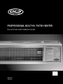
PROFESSIONAL BUILT-IN PATIO HEATER
Use and Care and Installation Guide
MODELS:
DRH-48N
A MESSAGE TO OUR CUSTOMERS
Thank you for selecting this DCS Professional Built-in Patio Heater. Because of this appliance’s unique features
we have developed this Use and Care and Installation Guide. It contains valuable information on how to properly
operate and maintain your new appliance for years of safe and enjoyable use.
To help serve you better, please fill out and submit your Ownership Registration by visiting our website at www.
dcsappliances.com and selecting “Customer Care” on the home page and then select “Product
Registration”. In addition, keep this guide handy, as it will help answer questions that may arise as you use your
new appliance.
For your convenience, product questions can be answered by a DCS Customer Care Representative at:
1-888-936-7872, email: [email protected]
NOTE: Please write the Model, Code, and Serial Numbers on this page for reference (located on right side near the
gas inlet).
MODEL NUMBER
CODE
SERIAL NUMBER
NOTE: Inspect the product to verify that there is no shipping damage. If any damage is detected, call the shipper
and initiate a damage claim. DCS by Fisher & Paykel is not responsible for shipping damage.
DO NOT discard any packing material (box, pallet, straps) until the unit has been inspected.
WARNING!
Do not try lighting this appliance without reading the “Lighting Instructions” section of this manual. Improper
installation, adjustment, alteration, service or maintenance can cause property damage, injury or death. Read the
installation, operating and maintenance instructions thoroughly before use, installing or servicing this equipment.
This outdoor gas appliance is not intended to be installed in or on recreational vehicles, boats or in a non-ventilated
room. For outdoor use only.
WARNING!
If the information in this manual is not followed exactly, a fire or explosion may result causing property damage,
personal injury or death. Do not store or use gasoline or other flammable vapors and liquids in the vicinity of this
or any other appliance. An LP cylinder not connected for use shall not be stored in the vicinity of this or any other
appliance.
DANGER
If You Smell Gas:
1. Shut off gas to the appliance.
2. Extinguish any open flames.
3. If odor continues, immediately call your gas supplier or your fire department
PLEASE RETAIN THIS MANUAL FOR FUTURE REFERENCE.
1
CONTENTS
SAFETY PRACTICES AND PRECAUTIONS
3-4
INSTALLATION
Locating Heater for Use
Installing the Heater
Gas Inlet Pressure
Clearance Specifications
Mounting
Electrical
Gas Piping
Ventilation
Leaking Test
5
6
6
7-11
12
12
12
13
13
USING THE HEATER
Lighting Instructions
14
WIRING/SCHEMATIC DIAGRAMS
15
SERVICE
16
WARRANTY
17-18
2
SAFETY PRACTICES AND PRECAUTIONS
When properly cared for, your Built-in Patio Heater will give safe, reliable service for many years. However,
extreme care must be used since the heater produces intense heat and can increase accident potential. When
using this appliance, basic safety practices must be followed, including the following:
■ Read this Use and Care and Installation Guide carefully and completely before using your heater to reduce the
risk of fire, burn hazard or other injury. Begin by ensuring proper installation and servicing. Do not repair
or replace any part of the heater unless specifically recommended in this manual. All other service should be
referred to a qualified technician.
WARNING!
Do not try lighting this appliance without reading the “LIGHTING INSTRUCTIONS” section of this manual.
■ Do not use in an explosive atmosphere. Keep heater away from areas where gasoline or other flammable liquids
or vapors are stored or used.
■ Before each use check for damaged parts such as hoses or burner.
■ Do not attempt to alter unit in any manner.
■ It is imperative that the control compartment, burners, and circulation air passageways of the heater must be
kept clean. The heater should be inspected before each use, and at least annually by a qualified service person,
for the presence of spiders, webs or other insects. The burner area is a common and desired spider haven.
INSECT WARNING!
Spiders and insects can nest in the burner of this and any other heater. Spider webs can present a dangerous
condition which can damage the heater and render it unsafe for use. Excessive or abnormal noises may be an indication of blockage by dirt, debris, spider webs, etc. Cleaning should be referred to a qualified technician.
■ Children should not be left alone or unattended in an area where the heater is being used. Never allow them to
sit, stand or play on or around the heater at any time. When in use, portions of the heater get hot enough to
cause severe burns.
■ Never let clothing, or other flammable materials come in contact with or too close to any part of heater or hot
surface until it has cooled. Fabric may ignite and result in personal injury.
■ Begin by insuring proper installation and servicing. Follow the installation instructions provided with this
product. Have your heater installed by a qualified technician. Have the installer show you where the gas supply
shut off valve is located so that you know where to shut off the gas to the heater. If you smell gas, your installer
has not done a proper job of checking for leaks. If the connections are not perfectly seated and tightened, you
can have a small leak and therefore a faint gas smell. Finding a leak is not a “do-it-yourself” procedure. Some
leaks can only be found with the heater in operation mode and for your protection it must be done by a
qualified service technician. Never use an open flame to locate leak.
WARNING!
Improper installation, adjustment, alteration, service or maintenance can cause property damage, injury or death.
Read the installation, operating and maintenance instructions thoroughly before installing or servicing this equipment.
3
SAFETY PRACTICES AND PRECAUTIONS
■ Clean the heater with caution. Avoid steam burns; do not use a wet sponge or cloth to clean the heater while it
is hot. Some cleaners produce noxious fumes or can ignite if applied to a hot surface.
■ Be sure all heater controls are turned off and the heater is cool before using any type of aerosol cleaner on or
around the heater. The chemical that produces the spraying action could, in the presence of heat, ignite or
cause metal parts to corrode.
■ Do not operate the heater under un protected combustible construction, maintain clearances. Use only in well
ventilated areas.
■ Keep the area surrounding the heater free from combustible materials, trash, or combustible fluids and vapors
such as gasoline or charcoal lighter fluid. Do not obstruct the flow of combustion and ventilation air.
■ To avoid the risk of burns or accidental cloth ignition, do not touch the heater anywhere near the burner
assembly during operation.
■ Do not touch the burner assembly until after the heater has cooled.
■ Carefully monitor young children in the vicinity of any operating heater.
■ Do not hang clothing or any other flammable materials from, on, or near the heater.
■ All leak tests should be done with a soap solution. Matches should never be used for this purpose.
■ This outdoor heater is primarily used for temporary heating of outdoor patios, decks, spa and pool area, and
work areas.
■ CALIFORNIA PROPOSITION 65-WARNING: The Burning of gas cooking fuel generates some by-products which
are on the list of substances which are known by the State of California to cause cancer or reproductive harm.
California law requires businesses to warn customers of potential exposure to such substances. To minimize
exposure to these substances, always operate this unit according to the Use and Care Guide, ensuring you
provide good ventilation when cooking with gas.
■ If the heater is used in locations where storage of combustible materials is allowed, a sign must be posted in a
conspicuous location specifying the maximum stacking height in order to maintain the required clearance to
combustible materials.
RECOMMENDATIONS ON HOOK-UP TO GAS SUPPLY:
A manual valve must be installed external to the appliance, in an accessible location from the front for the purpose of shutting off the gas supply. The supply line must not protrude beyond the back of the unit. Make sure
the gas supply is turned off at the wall valve before connecting the appliance.
The gas supply connections should be made by a qualified technician and in accordance with local codes or ordinances. In the absence of a local code, the installation must conform to the National Fuel Gas Code ANSI Z223.1.
Note:
This product must be installed by a licensed plumber or gas fitter when installed within the Commonwealth of
Massachusetts.
4
LOCATING HEATER FOR USE
This outdoor heater is used primarily for temporary heating of outdoor patios, decks, spa and pool area, and work
areas. This heater is not intended for indoor use or in an enclosed area. Always ensure that adequate fresh air
ventilation is provided.
WARNING!
Never operate in an explosive atmosphere. Keep away from areas where gasoline or other flammable liquids or
vapors are stored or used.
DEFINITION OF COMBUSTIBLE MATERIAL - Any materials of a building structure or decorative structure made of
wood, compressed paper, plant fibers or other materials that are capable of transferring heat or being ignited
and burned. Such material shall be considered combustible even though they may be flame-proofed, fire-retardant treated, or painted surface or plastered.
WARNING!
If a noncombustible material such as stucco is covering a combustible material such as wood, the minimum clearance distance needs to be held to the wood. The presence of a noncombustible material inside the clearance zone
does not eliminate the minimum clearance zone to combustible material.
DEFINITION OF NONCOMBUSTIBLE MATERIAL - Material which is not capable of being ignited and burned, such as materials consisting entirely of, or a combination of, steel, iron, brick tile, concrete, slate, and plaster.
WARNING!
The Built-in Heater is designed to function in an open area. Recommended minimum clearances should be maintained to all surfaces (combustible and noncombustible) for optimum performance. Noncombustible material within
the minimum clearance area could result in discoloration or deterioration. Do not place heater under a tarp or canvas cover.
5
INSTALLATION
INSTALLING THE HEATER:
The Built-in Patio Heater provides radiant warmth indoors (commercial applications only) or outdoors with a
powerful 56,000 Btu/hr natural gas. All units are equipped with hot surface ignition and 100% shutoff valve for
safety. Built-in Patio Heaters to be installed in Aircraft Hangers must be installed in accordance with American
National Standards for Aircraft Hangers, ANSI/NFPA No. 409. Heaters to be installed in public garages must be
installed in accordance with NFPA No. 88A standards for parking structures. Heaters must be installed so that
minimum clearances marked on the heater will be maintained from vehicles parked below the heater.
The installation must conform with ANSI standard No. Z223.1 National Fuel Gas Code and any applicable local
codes. In Canada, the installation must conform with local building codes or, in the absence of local codes, with
National Standards of Canada CAN/CGA-B 149.1 & 2-M86. Each heater must be electrically grounded in accordance with the National Electrical Code, ANSI/NFPA 70 when an external electrical source is utilized. In Canada,
the CSA Canadian Electrical Code, C22.1, Part 1 applies.
The gas inlet supply and normal operating manifold pressure for each heater are as follows. For gas supply line
pressures in excess of 1/2 psig, contact your dealer or Customer Care.
GAS INLET PRESSURE
Maximum: pressure Natural Gas: 1/2 psig
Minimum: pressure Natural Gas: 6” W.C.
Manifold: pressure Natural Gas: 5” W.C.
The heater has an internal 5” W.C. regulator.
Note:
This unit is for use with natural gas only.
WARNING!
1. When installing Mounting Body Assembly, make sure left hand and right hand Body Assembly are level. If not,
escaping heat could easily cause damage to the components inside the compartment.
2. When installing heater in the inverted orientation, please contact Customer Care at 1-888-936-7872. For special
instructions, see p/n 242420. Inverted installation to be performed by a qualified technician.
Normal Orientation
6
Inverted Orientation
INSTALLATION
CLEARANCE SPECIFICATIONS
0 0 & 45 0 INSTALLATION
MINIMUM CLEARANCES TO COMBUSTIBLE MATERIAL.
FRONT VIEW
Wall
(Combustible
Surface)
Wall
(Combustible
Surface)
Heater Mounting
Body Assy.
18"
18"
48"
min.
min.
96" min.
Make sure the heater is
level (see Warning on
page 6).
FLOOR
7
INSTALLATION
CLEARANCE SPECIFICATIONS
0 0 INSTALLATION
MINIMUM CLEARANCES TO COMBUSTIBLE MATERIAL.
SIDE VIEW
1/2"
Conduit
Gas Pipe
(installer
supplied)
Gas Shut-off
(installer supplied)
Valve
Four Bolts Two
(installer supplied) On Each Side
(installer supplied)
16"
min.
Drip Leg
Utilize 2
bolts (min)
with 1/8” NPT
per bracket
plugged test
gage connection
Utilize 2
bolts (min)
per bracket.
7-3/4"
18" min.
10-1/4"
120"
min.
96" min.
Note: Stainless steel hardware is highly
recommended. Bolts in the wall
should be secured to the wall
studs/structure. Weight of the
heater is 50 lbs.
FLOOR
8
Combustible
Surface
INSTALLATION
CLEARANCE SPECIFICATIONS
45 0 INSTALLATION
MINIMUM CLEARANCES TO COMBUSTIBLE MATERIAL.
SIDE VIEW
1/2"
Conduit
Combustible
Surface
4 Bolts per
Bracket
Gas Pipe
(installer
supplied)
(installer supplied)
(installer supplied)
25"
Gas Shut-off
Valve
min.
(installer supplied)
Utilize 2
Bolts (min)
per Bracket
12"
REF.
Drip Leg
with 1/8” NPT
plugged test
gage connection
18" min.
45 0
max.
130"
min.
96"
min.
Note: Stainless steel hardware is highly
recommended. Bolts in the wall
should be secured to the wall
studs/structure. Weight of the
heater is 50 lbs.
FLOOR
9
INSTALLATION
CLEARANCE SPECIFICATIONS
0 0 INSTALLATION
MINIMUM CLEARANCES TO NON-COMBUSTIBLE MATERIAL.
SIDE VIEW
Four Bolts
Per Bracket (installer supplied)
Non Combustible
Surface
(installer supplied)
Gas Shut-off
Valve
Utilize 2
bolts (min)
per bracket
Gas Pipe
(installer supplied)
1/2" Conduit
(installer
supplied)
Drip Leg
with 1/8” NPT
plugged test
gage connection
18" min.
96"
min.
Note: Stainless steel hardware is highly
recommended. Bolts in the wall
should be secured to the wall
studs/structure. Weight of the
heater is 50 lbs.
FLOOR
10
INSTALLATION
CLEARANCE SPECIFICATIONS
45 0 INSTALLATION
MINIMUM CLEARANCES TO NON-COMBUSTIBLE MATERIAL.
SIDE VIEW
Four Bolts
Per Bracket (installer supplied)
1/2" Conduit
(installer supplied)
Non Combustible
Surface
Gas
Shut-off
(installer supplied)
Valve
Utilize 2
bolts (min)
per bracket.
Gas Pipe
(installer supplied)
Drip Leg
with 1/8” NPT
plugged test
gage connection
18"min.
45 0
max.
96"
min.
Note: Stainless steel hardware is highly
recommended. Bolts in the wall
should be secured to the wall
studs/structure. Weight of the
heater is 50 lbs.
FLOOR
11
INSTALLATION
Do not locate either the gas or electrical supply line directly over the top of the heater, due to the extreme heat
that may cause overheating or damage. The heater must be installed in a location that is accessible for service.
The heater must be installed in a way that doesn’t restrict fresh airflow to the unit. The heater cannot be installed
in a recessed area. Doing so may cause poor performance and heat damage to the surrounding area.
MOUNTING
Each heater must be installed so that the minimum clearance to combustibles are maintained. Combustible
materials are defined as wood, paper, foliage, plastic, plexiglass or other materials capable of being ignited and
burned. Such materials shall be considered combustible even though flame-proofed, fire retardant treated or
plastered. Additional clearances may be required for glass, painted surfaces and other materials which may be
damaged by radiant or convection heat.
ELECTRICAL
Important!
A 24 VAC, 40 VA transformer has been included with the product. It is imperative to use this transformer.
The on-off control of the heater should be controlled from 120 VAC side of the transformer (see wiring diagram).
A UL approved outdoor wall switch must be used for this purpose. The transformer must be mounted a minimum of 12” from the heater in a weather protected cover. Do not put the transformer in the heater or above the
heater (this will damage the unit.) A step down transformer approved as having at least a 40 VA rating must be
utilized for each connected heater. Control wires used to electrically connect one or more heaters together must
have both adequate capacity and insulation temperature ratings for the total connected load. Use at least 18 ga.
wire up to 50 ft. from heater to transformer or wall switch. Use 16 ga. over 50 ft. distance. If the original wires
supplied should need replacement, they must be replaced with wiring material having a temperature rating of at
least 105 degrees Centigrade/221 º Fahrenheit.
GAS PIPING
A minimum pipe size of 1/2” is required for inlet piping. A 1/2” lever handled shut-off gas cock should be installed within 6 feet of the appliance for servicing the unit. Check with local and state plumbing and heating
codes regarding sizing of the gas lines. Installation of a drip leg in the gas supply line going to each heater is required to minimize the possibility of any loose scale or dirt within the gas supply line from entering the heater’s
control system. A 1/8” NPT plugged test gage connection is required immediately upstream of the gas supply
connection to the heater.
Gas Shut-off Valve
(installer supplied)
1/2"
Conduit
(installer
supplied)
Gas Pipe
(installer supplied)
Do not block
air inlets or
restrict airflow
to the air inlets
Drip Leg
with 1/8” NPT
plugged test
gage connection
Fig. 01
12
INSTALLATION
Important!
VENTILATION
A minimum building ventilation rate of 4 CFM per 1,000 BTU’s of installed heater input must be provided. This
rate of ventilation may be obtained through either gravity or mechanical ventilation of the building. In conjunction with building ventilation system, adequate fresh air into the building must be provided through fresh
air inlets and/or building inlets. It is recommended local code be checked to assure the ventilation system and
heat installation are in compliance with local and/or state codes.
When checking for gas leaks, do not use an open flame. Use a soap and water solution.
Note:
Gas connections on the heater are leak tested at the factory prior to shipment.
WARNING!
■ Periodically check the whole gas system for leaks or immediately check if the smell of gas is detected.
Extinguish all open flames.
■ Never leak test while smoking.
■ Do not use heater until all connections have been leak tested and do not leak.
■ When leak testing, refer to the connections diagrams.
■ Only those parts recommended by the manufacturer should be used.
■ Substitution can void warranty.
LEAK TEST:
Make a soap solution of one part liquid detergent, and one
part water. The soap solution can be applied with a spray
bottle, brush or rag. Soap bubbles will appear where a leak is
present.
Turn the gas supply “ON” check for leaks at leak points. If a
leak is present, turn off supply, tighten any leaking fittings,
turn gas on and recheck.
"OFF"
Note:
"ON" POSITION
FACTORY DEFAULT
There is a manual shut-off lever on the internal heater control
valve/regulator. This lever is shipped in the “ON” position Fig. 02 (Default position).
Fig. 02
13
USING THE HEATER
LIGHTING INSTRUCTIONS
TO LIGHT HEATER
Upon installation of the heater and completion of the gas line and electrical supply to each heater, follow the
steps below for Lighting Instructions. Lighting instructions are also provided on the control panel of the heater.
Turn gas and power to “ON”. The burner should light within the first 4 seconds. If not, the flame sensor will shut
off the mini-igniter. The unit will attempt to light 3 times before “locking out”. During initial installation, this
will happen if the gas line is not purged. To reset the control, shut off the power to the unit and wait 5 minutes.
Turn power back to “ON” position. This will allow for 3 more lighting attempts.
TO START HEATER
1. Turn manual gas valve to “ON” position.
2. Turn electrical supply “ON”.
TO SHUT DOWN HEATER
1. Turn electrical supply “OFF”.
2. Turn manual gas valve to “OFF” position.
WARNING!
If burner fails to ignite, shut down electrical power and wait 5 minutes before turning power “ON” to allow any gas
to dissipate.
A remote control accessory (DRH-RMT) is available. To order contact Customer Care at 1-888-936-7872.
WARNING!
Do not attempt to light this heater by hand.
14
WIRING/SCHEMATIC DIAGRAMS
FLAME
SENSOR
GAS
#2 VALVE #1
SHORT TO BYPASS
FLAME SENSOR
N
1. PUR - FLAME SENSOR
2. GRN - GROUND
3. BLU - GAS VALVE (TERM #1)
120 VAC
60 Hz
4. ORG - THERMOSTAT
24 VAC
FUSE
10 AMP - 32 VOLT
L1
5. (BLANK)
6. BLK - 24 VAC
7. RED - IGNITER
WIRING SCHEMATIC
IGNITER
2
1
GAS
VALVE
FLAME
SENSOR
SW
L1
N
GROUND
LUG
FUSE
MINI
IGNITER
1
2
3
4
5
6
7
24 VOLT AC
TRANSFORMER
IGNITION
MODULE
WIRING / COMPONENT DIAGRAM
15
SERVICE
HOW TO OBTAIN SERVICE:
For warranty service, please contact DCS Customer Care at (888) 936-7872, or go to our website at www.dcsappliances.com and choose “customer care” to find your nearest Authorized Service Center. Before you call, please
have the following information ready:
■ Model Number (located on right side near the gas inlet)
■ Serial Number (located on right side near the gas inlet)
■ Code (located on right side near the gas inlet)
■ Date of installation
■ A brief description of the problem
Your satisfaction is of the utmost importance to us. If a problem cannot be resolved to your satisfaction, please
email us at: [email protected] Or write:
Fisher & Paykel Appliances, Inc.
Attention: DCS Customer Care
5900 Skylab Road
Huntington Beach, CA 92647
www.dcsappliances.com
BEFORE YOU CALL FOR SERVICE:
1. Is the circuit breaker tripped or the fuse blown?
2. Is there a power outage in the area?
3. Check power to transformer (circuit breaker tripped).
4. Check for any sounds like clicking or humming coming from the heater unit with power turned on.
5. Make sure all gas valves are in the open position.
6. Is there a windy condition not allowing the unit to light?
7. Turn off the power supply for 5 minutes and restart.
16
WARRANTY
LIMITED WARRANTY
When you purchase a new DCS Professional Built-in Patio Heater you automatically receive a One Year Limited
Warranty covering parts and labor for the entire product, and a Five Year Limited Warranty on all stainless steel
components (excludes emitter screen, surface corrosion and discoloration) for servicing within the 48 mainland
United States, Hawaii, Washington D.C. and Canada. In Alaska, the Limited Warranty is the same except that you
must pay to ship the Product to the service shop or for the service technician’s travel to your home. Products for
use in Canada must be purchased through the Canadian distribution channel to ensure regulatory compliance.
FISHER & PAYKEL UNDERTAKES TO:
Repair without cost to the owner either for material or labor any part of the Product, the serial number of which
appears on the Product, which is found to be defective. In Alaska, you must pay to ship the Product to the
service shop or for the service technician’s travel to your home. If we are unable to repair a defective part of the
Product after a reasonable number of attempts, at our option we may replace the part or the Product, or we may
provide you a full refund of the purchase price of the Product (not including installation or other charges).
This warranty extends to the original purchaser and any succeeding owner of the Product for products
purchased for ordinary single-family home use. All service under this Limited Warranty shall be provided by
Fisher & Paykel Appliances Inc. or its Authorized DCS Service Agent during normal business hours.
HOW LONG DOES THIS LIMITED WARRANTY LAST?
Our liability under this Limited Warranty for the entire product expires One Year from the date of purchase of
the Product by the first consumer. Our liability under this Limited Warranty on all stainless steel components
(excludes emitter screen, surface corrosion and discoloration) expires Five Years from the date of purchase of the
Product by the first consumer.
Our liability under any implied warranties, including the implied warranty of merchantability (an unwritten
warranty that the Product is fit for ordinary use) also expires One Year (or such longer period as required by applicable law) from the date of purchase of the Product by the first consumer. Some states do not allow limitations
on how long an implied warranty lasts, so this limit on implied warranties may not apply to you.
THIS WARRANTY DOES NOT COVER:
A. Service calls that are not related to any defect in the Product. The cost of a service call will be charged if the
problem is not found to be a defect of the Product. For example:
1. Correct faulty installation of the Product.
2. Instruct you how to use the Product.
3. Replace house fuses, reset circuit breakers, correct house wiring or plumbing, or replace light bulbs.
4. Correct fault(s) caused by the user.
5. Change the set-up of the Product.
6. Unauthorized modifications of the Product.
7. Noise or vibration that is considered normal, for example, drain/fan sounds, regeneration noises or user
warning beeps.
8. Correcting damage caused by pests, for example, rats, cockroaches etc.
B. Defects caused by factors other than:
1. Normal domestic use or
2. Use in accordance with the Product’s Use and Care Guide.
C. Defects to the Product caused by accident, neglect, misuse, fire, flood or Act of God.
17
WARRANTY (CONTINUED)
D. The cost of repairs carried out by non-authorized repairers or the cost of correcting such unauthorized repairs.
E. Travel Fees and associated charges incurred when the product is installed in a location with limited or restricted
access (i.e. airplane flights, ferry charges, isolated geographic areas).
F. Normal recommended maintenance as set forth in the Product’s Use and Care Guide.
If you have an installation problem contact your dealer or installer. You are responsible for providing adequate
electrical, exhausting and other connection facilities. We are not responsible for consequential or incidental
damages (the cost of repairing or replacing other property damaged if the Product is defective or any of your
expenses caused if the Product is defective). Some states do not allow the exclusion or limitation of incidental or
consequential damages, so the above limitation or exclusion may not apply to you.
HOW TO GET SERVICE
Please read your Use and Care Guide. If you then have any questions about operating the Product, need the
name of your local DCS Authorized Service Agent, or believe the Product is defective and wish service under this
Limited Warranty, please contact your dealer or call us at:
TOLL FREE 1-888-936-7872 or contact us through our web site: www.dcsappliances.com.
You may be required to provide reasonable proof of the date of purchase of the Product before the Product will
be serviced under this Limited Warranty.
COMMERCIAL USE
This warranty applies to appliances used in residential applications; it does not cover their use in commercial
situations.
NO OTHER WARRANTIES
This Limited Warranty is the complete and exclusive agreement between you and Fisher & Paykel Appliances Inc.
regarding any defect in the Product. None of our employees (or our Authorized Service Agents) are authorized to
make any addition or modification to this Limited Warranty.
Warrantor: Fisher & Paykel Appliances, Inc.
If you need further help concerning this Limited Warranty, please call us at the above number, or write to:
Fisher & Paykel Appliances, Inc.
Attention: DCS Customer Care
5900 Skylab Road, Huntington Beach, CA 92647
This Limited Warranty gives you specific legal rights, and you may also have other rights which vary from state to
state.
Fisher & Paykel Appliances Inc. is a leading manufacturer of premium quality cooking and specialty appliances
under the Fisher & Paykel and DCS brands.
18
NOTES
19
NOTES
20
CHAUFFRETTE PROFESSIONNELLE
Manuel d’utilisation et d’entretien
MODÈLES :
DCS-DRH48N
À L’INTENTION DE NOS CLIENTS
Merci d’avoir sélectionner l’appareil de chauffage incorporé professionnel pour patio DCS. Nous avons conçu ce
Manuel d’utilisation et d’entretien et d’installation pour expliquer ses fonctions uniques. Il contient des informations extrêmement utiles sur la façon de faire fonctionner et d’entretenir correctement votre nouvel appareil.
Vous pourrez ainsi en profiter pendant des années en toute sécurité.
Aidez-nous à mieux vous servir en remplissant la Carte d’enregistrement du propriétaire et en nous la soumettant depuis notre site Web à www.dcsappliances.com. Sélectionnez « Customer Care » sur la page d’accueil puis
« Product Registration ». De plus, gardez ce manuel à portée de main afin de rapidement trouver réponse à vos
questions lorsque vous utilisez votre nouvel appareil.
Si vous avez des questions au sujet de notre produit, contactez le Centre de service à la clientèle DCS par téléphone : 1-888-936-7872, ou par courriel : [email protected].
REMARQUE : Veuillez noter les numéros de modèle, code, et de série sur cette page pour information (situé sur la
droite près de l’arrivée du gaz).
NUMÉRO DE MODÈLE
CODE
NUMÉRO DE SÉRIE
REMARQUE : Inspecter le produit pour vérifier qu’il n’a pas été endommagé pendant l’expédition. En cas de dommages, contacter le transporteur et entamer une déclaration pour dommage. DCS by Fisher & Paykel n’est en
aucun cas responsable des dommages pendant l’expédition.
Ne pas jeter le matériau d’emballage (boîte, palette, sangles) avant d’avoir inspecté l’unité.
AVERTISSEMENT!
N’essayez pas d’allumer l’appareil sans avoir lu la section « Instructions d’allumage » de ce manuel. Toute installation, ajustement, altération ou entretien incorrect peut causer des dommages matériels, des blessures ou la mort.
Veuillez lire soigneusement ces instructions d’installation, d’utilisation et d’entretien avant d’utiliser, installer ou
effectuer l’entretien de cet appareil. Cet appareil à gaz pour l’extérieur n’est pas conçu pour être installé dans ou sur
des véhicules récréatifs, des bateaux ou dans une pièce sans aération. Pour usage en plein air uniquement.
AVERTISSEMENT!
Si les informations de ce manuel ne sont pas suivies à la lettre, un incendie ou une explosion peuvent se produire et
causer des dommages matériels, des blessures ou la mort. Évitez de stocker ou d’utiliser de l’essence ou tous autres
liquides et vapeurs inflammables à proximité de cet appareil ou de tout autre appareil électroménager. Évitez de
ranger une bouteille de gaz propane (qui n’est pas connectée car non utilisée) à proximité de cet appareil électroménager ou de tout autre.
DANGER
Si vous sentez une odeur de gaz :
1. Coupez l’arrivée de gaz de l’appareil.
2. Éteignez toute flamme vive.
3. Si l’odeur persiste, appelez immédiatement votre fournisseur de gaz.
VEUILLEZ CONSERVER CE MANUEL À TITRE DE RÉFÉRENCE.
1
TABLE DES MATIÈRES
MESURES DE SÉCURITÉ ET DE PRÉCAUTION
3-4
INSTALLATION
Enplacement
Installation de la chauffrette
Pression d’admission de gaz
Spécification concernant les dégagements
Installation
Caractéristiqus électriques
Tuyaux de gaz
Ventilation
Test de détection des fuites
5
6
6
7-11
12
12
12
13
13
UTILISATION DE LA CHAUFFRETTE
Instructions d’allumage
14
ENTRETIEN ET NETTOYAGE
14
SCHÉMA DE CÂBLAGE
15
SERVICE
16
GARANTIE
17-18
2
MESURES DE SÉCURITÉ ET DE PRÉCAUTION
■ L’appareil de chauffage fonctionnera de manière sûre et fiable pendant des années si vous en prenez soin
correctement. Vous devez toutefois faire très attention car l’appareil dégage une chaleur intense et peut augmenter les risques d’accident. Vous devez respecter des consignes de sécurité élémentaires durant l’utilisation,
dont celles-ci :
■ Lisez ce Manuel d’utilisation et d’entretien attentivement et intégralement avant d’utiliser l’appareil afin de
réduire les risques d’incendie, de brûlures et de blessures. Commencez par vous assurer que l’installation et
l’entretien sont effectués correctement. Ne réparez pas ni ne remplacez aucune pièce de l’appareil, sauf indication contraire du manuel. Tout autre service doit être confié à un technicien qualifié.
AVERTISSEMENT!
N’essayez pas d’allumer l’appareil sans avoir lu la section « INSTRUCTIONS D’ALLUMAGE » de ce manuel.
■ N’utilisez pas l’appareil dans une atmosphère explosive. Conservez-le loin des endroits où sont entreposés ou
utilisés des liquides ou des produits aux vapeurs inflammables.
■ Avant chaque utilisation, inspectez l’appareil afin de détecter toute détérioration des tuyaux ou du brûleur.
■ N’essayez pas de modifier l’appareil de quelque manière que ce soit.
■ Il est essentiel de veiller au dégagement et à la propreté du panneau de commande, des brûleurs et de
l’alimentation en air de l’appareil. Inspectez l’appareil avant chaque utilisation et faites-le inspecter au moins une
fois l’an par un technicien qualifié, afin de vérifier la présence de toiles d’araignées ou d’insectes. Les araignées
semblent avoir un faible pour le brûleur et il arrive qu’elles s’y introduisent.
AVERTISSEMENT CONCERNANT LES INSECTES!
Les araignées et les insectes peuvent se loger dans le brûleur de cette chauffrette ou des appareils similaires. Les
toiles d’araignées peuvent également endommager l’appareil et le rendre dangereux.
■ Ne laissez pas les enfants seuls dans un endroit où l’appareil est utilisé. Ne les laissez pas s’asseoir, monter ou
jouer sur l’appareil ou à proximité. Certaines parties de l’appareil chauffent durant son utilisation au point de
causer des brûlures.
■ Ne laissez jamais des vêtements ou autres matériaux inflammables en contact ou à proximité d’une partie
quelconque de l’appareil ou d’une surface chaude tant que celles-ci n’ont pas refroidi. Les tissus peuvent
s’enflammer et causer des blessures.
■ Commencez par vous assurer que l’installation et l’entretien sont effectués correctement. Suivez les instructions
d’installation fournies avec ce produit. Faites installer l’appareil par un technicien qualifié. Demandez-lui de vous
montrer l’emplacement du robinet d’arrêt de l’alimentation de gaz afin de savoir comment couper l’arrivée de
gaz de l’appareil. Si vous sentez une odeur de gaz, cela signifie que l’installateur n’a pas vérifié correctement s’il
y avait des fuites. Si les connexions ne sont pas bien mises et bien serrées, une petite fuite pourrait se produire
et laisser s’échapper une faible odeur de gaz. La détection des fuites n’est pas une procédure à faire soi-même.
Certaines fuites ne peuvent être détectées que si l’appareil est en mode de fonctionnement. Dans l’intérêt de
votre sécurité, confiez cette procédure à un technicien qualifié. N’effectuez jamais d’épreuve d’étanchéité à l’aide
d’une flamme vive.
AVERTISSEMENT!
Toute installation, ajustement, altération ou entretien incorrect peut causer des dommages matériels, des blessures
ou la mort. Veuillez lire soigneusement ces instructions d’installation, d’utilisation et d’entretien avant d’installer ou
d’effectuer l’entretien de cet appareil.
3
MESURES DE SÉCURITÉ ET DE PRÉCAUTION
■ Nettoyez l’appareil avec précaution. Évitez de vous brûler à la vapeur; n’utilisez pas d’éponge ou de chiffon
mouillé pour nettoyer l’appareil s’il est chaud. Certains produits de nettoyage produisent des vapeurs nocives ou
peuvent prendre feu s’ils sont appliqués à une surface chaude.
■ Assurez-vous que les boutons de l’appareil sont fermés et que celui-ci est froid avant d’utiliser des nettoy-
ants aérosol dessus ou à proximité. L’élément chimique qui produit le jet de vaporisation peut, en présence de
chaleur, s’enflammer ou provoquer la corrosion des parties métalliques.
■ Ne faites pas fonctionner l’appareil sous une construction combustible non protégée; respectez les dégagements
préconisés. Utilisez-le seulement dans un lieu bien aéré.
■ Gardez la zone entourant l’appareil libre de matériaux combustibles et de rebus, ou de fluides et vapeurs
combustibles tels que l’essence ou du liquide d’allumage pour charbon de bois. N’obstruez pas le débit de l’air
de combustion et de ventilation.
■ Afin d’éviter que vous ne vous brûliez ou que vos vêtements ne prennent feu, ne touchez aucune partie proche
du brûleur de l’appareil lorsque celui-ci est en cours d’utilisation.
■ Laissez refroidir l’appareil avant de toucher au brûleur.
■ Surveillez toujours les enfants lorsqu’ils sont à proximité de l’appareil et que celui-ci est en fonctionnement.
■ Ne suspendez pas ni ne déposez de vêtement ou de matière inflammable sur l’appareil ou à proximité.
■ Recherchez toute fuite au moyen d’une solution savonneuse. N’utilisez jamais une allumette à cette fin.
■ Cet appareil d’extérieur est principalement conçu pour le chauffage temporaire des patios, terrasses, spa et
piscines et chantiers en plein air.
■ AVERTISSEMENT CONCERNANT LA PROPOSITION 65 DE LA CALIFORNIE : L’incinération de gaz de cuisson
génère des sous-produits faisant partie des substances considérées par l’État de Californie comme pouvant
causer le cancer ou des malformations congénitales. Les lois de Californie exigent que les entreprises avertissent
leurs clients qu’ils risquent d’être exposés à de telles substances. Pour minimiser l’exposition à ces substances,
faites toujours fonctionner cet appareil conformément au manuel d’utilisation et d’entretien, en assurant une
bonne ventilation lorsque vous cuisinez au gaz.
■ Si l’appareil de chauffage est utilisé dans des endroits où l’entreposage de matières combustibles est autorisé,
un panneau doit être affiché dans un endroit bien visible, spécifiant la hauteur de gerbage maximum afin de
maintenir le dégagement requis par rapport aux matières combustibles.
RECOMMANDATIONS CONCERNANT LE BRANCHEMENT DU GAZ :
Un robinet manuel doit être installé à l’extérieur de l’appareil, sur le devant, dans un endroit accessible, afin
de permettre de couper le gaz. La conduite d’alimentation ne doit pas dépasser l’arrière de l’appareil. Avant de
brancher l’appareil, prenez soin de couper le gaz par le robinet mural.
Toutes les connexions d’alimentation en gaz doivent être effectuées par un technicien qualifié conformément
aux codes et règlements en vigueur. En l’absence de codes locaux, l’installation doit être conforme à la norme
ANSI Z223.1, du National Fuel Gas Code.
Remarque :
Ce produit doit être installé par un plombier ou ajusteur d’appareils à gaz agréé si l’installation a lieu au sein du
Commonwealth du Massachusetts.
4
EMPLACEMENT
Cette chaufferette d’extérieur est principalement conçue pour le chauffage temporaire des patios, terrasses, spa et piscines
et chantiers en plein air. N’utilisez pas cette chaufferette à l’intérieur ou dans un endroit fermé. Assurez-vous toujours que
l’aération est suffisante.
AVERTISSEMENT!
N’utilisez jamais cette chaufferette dans une atmosphère explosive, ni dans un endroit où l’on conserve ou utilise de
l’essence ou tout autre produit inflammable.
DÉFINITION DES MATÉRIAUX COMBUSTIBLES -Tout matériau de structure de construction ou structure décorative
fabriquée en bois, papier comprimé, fibres de plante ou autres matériaux capables de transférer la chaleur ou
d’être enflammé et brûlé. Ledit matériau sera considéré combustible même si ignifugé ou revêtu de peinture ou
de plâtre.
AVERTISSEMENT!
Si un matériau non combustible tel que le stucco recouvre un matériau combustible, du bois par exemple, maintenez la distance de dégagement minimum avec celui-ci.La présence de matériaux non combustibles à l’intérieur de
la zone de dégagement n’est pas une raison pour ignorer la zone de dégagement minimum à maintenir jusqu’aux
matériaux combustibles.
DÉFINITION DES MATÉRIAUX NON COMBUSTIBLES - Matériaux qui ne sont pas susceptibles de s’allumer et de brûler tels
que les matériaux composés entièrement ou partiellement d’acier, de fer, de briques, de tuiles, de béton, d’ardoise ou de
plâtre.
AVERTISSEMENT!
La chaufferette de patio autonome est conçue pour fonctionner dans une aire ouverte. Respectez le dégagement
minimum recommandé pour toutes les surfaces (combustibles et non combustibles) pour un rendement optimal.La
présence de matériaux non combustibles dans la zone de dégagement minimum peut entraîner une décoloration
ou une détérioration. Ne pas placer l’appareil de chauffage sous une bâche ou une housse en toile.
5
INSTALLATION
INSTALLATION DE LA CHAUFFRETTE:
L’appareil de chauffage intégré de terrasse fournit une chaleur rayonnante à l’intérieur.(applications commerciales seulement) ou à l’extérieur grâce à son puissant débit de 56 000 BTUH (gaz naturel). Tous les appareils
sont équipés d’un module d’inflammation de surface chaude et d’un robinet d’arrêt intégral pour raison de
sécurité. L’installation des chauffrettes Del Rey dans des hangars aériens doit l’être conformément aux exigences
des American National Standards for Aircraft Hangers, ANSI/NFPA No. 409. Toute installation dans des aires de
garage publiques doit l’être conformément aux exigences NFPA No. 88A concernant les bâtiments servant au
stationnement de voitures. Les appareils doivent être installés de sorte à respecter entre les véhicules stationnés
et les chauffrettes les dégagements minimum indiqués sur ces dernières.
L’installation doit être conforme à la norme ANSI Z223.1 du National Fuel Gas Code et à tout code en vigueur.
L’installation au Canada doit être conforme aux codes du bâtiment en vigueur ou, en l’absence de tels codes,
aux Normes nationales du Canada CAN/CGA-B 149.1 & 2-M86. Chaque appareil doit être mis électriquement à la
terre conformément à la norme ANSI/NFPA 70 du National Electrical Code, et, au Canada, au Code canadien de
l’électricité, Première partie, C22.1 de l’ACNOR.
L’admission de gaz et la pression d’utilisation normale du collecteur sont comme suit : Pour les pressions de
conduite d’alimentation en gaz dépassant 3,45 kPa (1/2 psig), contactez votre distributeur ou le Centre de service à la clientèle.
PRESSION D’ADMISSION DE GAZ
Maximum : pression, gaz naturel : 3,45 kPa (1/2 psig)
Minimum : pression, gaz naturel : 6 po C.E.
Collecteur : pression, gaz naturel : 5 po C.E.
L’appareil comporte un régulateur interne de 5 po C.E.
Remarque :
Cet appareil est conçu pour une utilisation avec du gaz naturel seulement.
AVERTISSEMENT!
1. Ce produit doit être installé par un plombier ou un ajusteur d’appareils à gaz agréé si l’installation est effectuée
dans le Commonwealth du Massachusetts.
2. Pour installer l’appareil de chauffage dans le sens inverse, contacter le Service à la clientèle au 1-888-936-7872.
Pour instructions spéciales, voir réf. 242420. Une installation inversée doit être effectuée par un technicien
qualifié.
Orientation normale
Orientation inversée
6
INSTALLATION
SPÉCIFICATION CONCERNANT LES DÉGAGEMENTS
DÉGAGEMENTS
INSTALLATION À 0º ET 45º
DÉGAGEMENTS MINIMUM PAR RAPPORT À DES MATÉRIAUX COMBUSTIBLES.
VUE DE FACE
Mur
(Surface combustible)
Mur
(Surface combustible)
Corps du support de
la chaufferette
45,7 cm min./
18 po min.
121,9 cm/48 po
243,8 cm/96 po min.
Assurez-vous que la
chaufferette est de niveau
(voir avertissement à la page 6)
PLANCHER
7
45,7 cm min./
18 po min.
INSTALLATION
SPÉCIFICATION CONCERNANT LES DÉGAGEMENTS
INSTALLATION À 0º
DÉGAGEMENTS MINIMUM PAR RAPPORT À DES MATÉRIAUX COMBUSTIBLES.
VUE LATÉRALE
Tube 1,3 cm
(1/2 po)
(fourni par
l'installateur)
Tuyau de gaz
Robinet d'arrêt de
l'alimentation de gaz
(fourni par l'installateur)
(fourni par l'installateur)
Surface
combustible
Quatre boulons,
deux de
chaque côté
40,6 cm min./
16 po min.
(fourni par l'installateur)
Point de purge avec
connexion de
manomètre d'essai
1/8” NPT branché.
Utilisez 2
boulons (min.)
par support.
Utilisez 2
boulons
(min.) par
support.
19,7 cm/7-3/4 po
45,7 cm min./18 po min.
26 cm/10-1/4 po
304,8 cm/
120 po
243,8 cm min./
96 po min.
Remarque : il est fortement recommandé
d’utiliser une visserie en acier inoxydable. Les
boulons dans le mur doivent être fixés dans les
poteaux muraux ou la structure. L’appareil de
chauffage pèse 22,6 kg (50 lb).
PLANCHER
8
INSTALLATION
SPÉCIFICATION CONCERNANT LES DÉGAGEMENTS
INSTALLATION À 45º
DÉGAGEMENTS MINIMUM PAR RAPPORT À DES MATÉRIAUX COMBUSTIBLES.
VUE LATÉRALE
Tube 1,3 cm
(1/2 po)
Surface
combustible
Quatre
boulons
par côté
Tuyau de gaz
(fourni par l'installateur)
(fourni par
l'installateur)
Robinet d'arrêt (fourni par
de l'alimentation l'installateur)
de gaz
63,5 cm min./
25 po min.
(fourni par l'installateur)
Utilisez 2
boulons (min.)
par support.
30,5 cm /
12 po
RÉF.
Point de purge avec
connexion de
manomètre d'essai
1/8” NPT branché.
45,7 cm min./
18 po min.
0
330,2 cm/
130 po
243,8 cm min./
96 po min.
45
max.
Remarque : il est fortement recommandé
d’utiliser une visserie en acier inoxydable. Les
boulons dans le mur doivent être fixés dans les
poteaux muraux ou la structure. L’appareil de
chauffage pèse 22,6 kg (50 lb).
PLANCHER
9
INSTALLATION
SPÉCIFICATION CONCERNANT LES DÉGAGEMENTS
INSTALLATION À 0º
DÉGAGEMENTS MINIMUM PAR RAPPORT À DES MATÉRIAUX NON COMBUSTIBLES.
VUE LATÉRALE
Quatre boulons
par support
Utilisez 2
boulons (min.)
par support.
Tuyau de gaz
(fourni par l'installateur)
Surface
combustible
Robinet d'arrêt de
l'alimentation de gaz
Tube 1,3 cm
(1/2 po)
(fourni par l'installateur)
(fourni par
l'installateur)
Point de purge avec
connexion de
manomètre d'essai
1/8” NPT branché.
243,8 cm min./
96 po min.
Remarque : il est fortement recommandé
d’utiliser une visserie en acier inoxydable. Les
boulons dans le mur doivent être fixés dans les
poteaux muraux ou la structure. L’appareil de
chauffage pèse 22,6 kg (50 lb).
PLANCHER
10
INSTALLATION
SPÉCIFICATION CONCERNANT LES DÉGAGEMENTS
INSTALLATION À 45º
DÉGAGEMENTS MINIMUM PAR RAPPORT À DES MATÉRIAUX NON COMBUSTIBLES.
VUE LATÉRALE
Quatre boulons
par côté
Utilize 2
bolts (min)
per bracket
Tuyau de gaz
(fourni par
l'installateur)
Tube 1,3 cm
(1/2 po)
(fourni par
l'installateur)
Surface
combustible
Robinet d'arrêt
de l'alimentation
de gaz
(fourni par l'installateur)
Point de purge avec
connexion de
manomètre d'essai
1/8” NPT branché.
45 0
max.
243,8 cm min./
96 po min.
Remarque : il est fortement recommandé
d’utiliser une visserie en acier inoxydable. Les
boulons dans le mur doivent être fixés dans les
poteaux muraux ou la structure. L’appareil de
chauffage pèse 22,6 kg (50 lb).
PLANCHER
11
INSTALLATION
Ne pas placer de conduite d’alimentation au gaz ou électrique directement sur la sortie de l’appareil de chauffage et ce, en raison de l’extrême chaleur susceptible de provoquer une surchauffe ou des dommages.
L’appareil de chauffage doit être installé dans un endroit accessible pour l’entretien. L’appareil de chauffage doit
être installé de manière à ne pas restreindre l’écoulement d’air frais vers l’unité. L’appareil de chauffage ne peut
pas être installé dans un endroit encastré et ce, pour ne pas entraîner une mauvaise performance ou des
dommages par échauffement de la zone environnante.
INSTALLATION
Chaque appareil doit être installé de façon à respecter les dégagements minimum préconisés pour les matériaux combustibles : bois, papier, feuillage, plastique, plexiglas ou autres matériaux capables de prendre feu et
de brûler. Ces matériaux sont considérés comme étant combustibles même s’ils ont été ignifugés. Le verre, les
surfaces peintes ou d’autres matériaux pouvant être endommagés par de la chaleur radiante ou de convection
nécessitent des dégagements plus grands.
CARACTÉRISTIQUES ÉLECTRIQUES
Important!
Un transformateur de 24 V c.a., 40 VA a été inclus avec le produit. Son utilisation est obligatoire.
La commande marche-arrêt de l’appareil doit être contrôlée à partir du côté à 120 V c.a. du transformateur.
Utilisez une prise murale extérieure homologuée UL à cette fin. Installez le transformateur à 30,5 cm (12 po) au
moins de la chauffrette, dans un couvercle de protection contre les intempéries. Ne pas mettre le transformateur
dans l’appareil de chauffage ou au-dessus de celui-ci (cela endommagerait celle-ci). Utilisez un transformateur
abaisseur de 40 VA au moins pour chaque chauffrette branchée. Les fils de commande connectant électriquement
une ou plusieurs chauffrettes ensemble doivent posséder une capacité adéquate et une température nominale
d’isolation pour la charge connectée totale. Utilisez des fils de calibre 18 au moins et de 15 m (50 pi) maximum de
la chauffrette au transformateur ou à la prise murale. Utilisez des fils de calibre 16 si la distance est supérieure à
15 m. Si les fils d’origine doivent être remplacés, remplacez-les par des fils possédant une température nominale
d’au moins 105 degrés centigrades.
TUYAUX DE GAZ
La tuyauterie d’arrivée exige un tuyau de 2,5 cm (1/2 po) minimum. Installez un robinet d’arrêt de gaz à levier
de 2,5 cm (1/2 po) à moins de 2 mètres (6 pieds) de l’appareil. Consultez les codes de plomberie et de chauffage
locaux et provinciaux en vigueur en ce qui concerne les dimensions des lignes de gaz. L’installation d’un point de
purge dans la conduite d’alimentation en gaz reliant chaque chauffrette est requise afin de minimiser le risque
de pénétration de tartre ou de saleté dans le système de contrôle de l’appareil par la conduite. Une connexion de
manomètre d’essai 1/8” NPT branché est requises immédiatement en amont de la connexion d’alimentation en gaz vers
l’appareil de chauffage.
Tube 1,3 cm
(1/2 po)
(fourni par
l'installateur)
Tuyau de gaz
(fourni par l'installateur)
Ne pas
bloquer les
arrivées d’air
ou restreindre le débit
d’air vers
les arrivées
d’air.
Point de purge avec
connexion de
manomètre d'essai
1/8” NPT branché.
19,7 cm /
7-3/4 po
Fig. 01
12
INSTALLATION
Important!
VENTILATION
Assurez une ventilation de bâtiment minimum de 0,11 m3/min (4 pi3/min) par 1000 BTU de chaleur fournis.
Ce taux de ventilation peut être obtenu par gravité ou ventilation mécanique du bâtiment. Parallèlement au
système de ventilation du bâtiment, assurez une circulation d’air frais adéquate par l’intermédiaire d’entrées
d’air frais et/ou entrées d’air du bâtiment. Il est recommandé de vérifier la réglementation en vigueur pour
s’assurer que le système de ventilation et l’installation de chauffage sont conformes aux codes locaux ou provinciaux.
Ne vérifiez jamais s’il y a des fuites à l’aide d’une flamme vive. Utilisez plutôt une solution d’eau savonneuse.
Remarque :
Le fabricant a procédé à une vérification des fuites sur les connexions de gaz de l’appareil avant la livraison.
AVERTISSEMENT!
■ Inspectez de temps à autre tout le système à gaz pour voir s’il y a des fuites ou immédiatement si vous
détectez une odeur de gaz. Éteignez toute flamme vive.
■ Ne fumez jamais lorsque vous vérifiez s’il y a des fuites.
■ N’utilisez pas l’appareil avant d’avoir vérifié tous les raccords et de vous être assuré qu’il n’y a pas de fuites.
■ Lorsque vous vérifiez s’il y a des fuites, reportez-vous aux illustrations.
■ Utilisez uniquement les pièces recommandées par le fabricant.
■ Toute substitution peut annuler la garantie.
DÉPISTAGE DES FUITES :
Préparez une solution savonneuse composée à moitié de détergent
liquide et à moitié d’eau. Appliquez la solution savonneuse au moyen
d’un vaporisateur, d’une brosse ou d’un chiffon. S’il y a une fuite, des
bulles de savon se formeront.
OFF (Arrêt)
Ouvrez l’alimentation et vérifiez si du gaz s’échappe. En cas de fuite,
fermez l’alimentation, serrez les raccords qui fuient, ouvrez le gaz et
vérifiez de nouveau.
Remarque :
La valve de réglage/régulateur interne de l’appareil comporte un levier
d’arrêt manuel. Ce levier est livré en position « ON » Fig. 02 (position par défaut).
POSITION « ON »
RÉGLAGE PAR
DÉFAUT
Fig. 02
13
UTILISATION DE LA CHAUFFRETTE
INSTRUCTIONS D’ALLUMAGE
INSTRUCTIONS D’ALLUMAGE
Après l’installation de la chauffrette et le branchement de la conduite de gaz et de la ligne électrique à chaque
appareil, suivez la procédure ci-dessous en ce qui concerne les instructions d’allumage. Le panneau de contrôle
de l’appareil comporte également des instructions d’allumage.
Ouvrez le gaz et allumez l’appareil « ON ». Le brûleur devrait s’allumer en moins de 4 secondes. Dans le cas contraire, le capteur d’électrode éteint l’électrode de la surface chaude. L’électrode tente d’allumer le brûleur 3 fois
avant de se « verrouiller ». Durant l’installation initiale, ceci se produit si la conduite de gaz n’est pas purgée. Pour
réinitialiser le dispositif de contrôle, éteignez l’appareil et attendez 5 secondes. Allumez l’appareil de nouveau
position « ON ». Ceci permet 3 nouvelles tentatives d’allumage.
POUR DÉMARRER LA CHAUFFRETTE
1. Mettez la valve à gaz manuelle sur « ON ».
2. Mettez l’alimentation électrique sur « ON ».
POUR ÉTEINDRE LA CHAUFFRETTE
1. Mettez l’alimentation électrique sur « OFF ».
2. Mettez la valve à gaz manuelle sur « OFF ».
AVERTISSEMENT!
Si le brûleur ne s’allume pas, coupez le courant et attendez 5 minutes avant de le rétablir afin de permettre au gaz
de se dissiper.
Un accessoire de modèle à télécommande (DRH-RMT) est disponible. Pour commander, contacter le service clientèle
en composant le 1-888-936-7872.
AVERTISSEMENT!
Re pas tenter d’allumer cet appareil de chauffage à la main.
14
SCHÉMA DE CÂBLAGE
Détecteur de flamme
Robinet de gaz
#2
#1
Court-circuit pour éviter
détecteur de flamme
1. Violet – détecteur de flamme
2. Vert – terre
3. Bleu – robinet de gaz (term n° 1)
4. Orange - thermostat
5. (vierge)
6. Noir - 24 V c.a.
7. Rouge – allumeur
Neutre
120 V c.a.,
60 Hz
24 V c.a.
Fusible 10 A - 32 volts
Ligne 1
Schéma de câblage
Allumeur
Robinet
de gaz
2
1
Détecteur de flamme
Commutateur
Ligne 1
Neutre
Patte de
terre
Fusible
Mini-allumeur
Schéma de câblage/des composants
15
1
2
3
4
5
6
7
Module
d'allumage
24 V c.a.
Transformateur
SERVICE
POUR L’OBTENTION DU SERVICE DE GARANTIE :
Pour le service sous garantie, contactez le Centre de service à la clientèle DCS au (888) 936-7872 ou consulter
notre site Web www.dcsappliances.com et choisir « Customer Care » pour trouver le Centre de service le plus
proche.
Avant d’appeler, veuillez avoir les informations suivantes à portée de main :
■ Numéro de modèle (situé sur la droite près de l’arrivée du gaz).
■ Numéro de série (situé sur la droite près de l’arrivée du gaz).
■ Code (situé sur la droite près de l’arrivée du gaz).
■ Date d’installation
■ Brève description du problème
Votre satisfaction revêt la plus grande importance pour nous. Si un problème n’est pas résolu à votre entière satisfaction, veuillez communiquer avec nous par courrier : [email protected]
Écrivez-nous à l’adresse suivante :
Fisher & Paykel Appliances, Inc.
Attention : DCS Customer Care
5900 Skylab Road
Huntington Beach, CA 92647 États-Unis
www.dcsappliances.com
AVANT D’APPELER LE SERVICE TECHNIQUE :
1. Est-ce que le disjoncteur s’est déclenché ou que le fusible est grillé?
2. Y a-t-il une coupure de courant dans le secteur?
3. Vérifiez la présence de courant au niveau du transformateur (disjoncteur déclenché).
4. Vérifiez s’il y a des déclics ou un bourdonnement provenant de la chauffrette lorsque celle-ci est allumée.
5. Assurez-vous que toutes les valves à gaz sont ouvertes.
6. Est-ce que le vent empêche l’appareil de s’allumer?
7. Coupez le courant électrique pendant 5 minutes puis redémarrez.
16
GARANTIE
GARANTIE LIMITÉE
Lors de l’achat d’une nouvel Appareil de chauffage intégré de terrasse DCS Professional, vous bénéficiez automatiquement d’une garantie limitée d’un an couvrant les pièces et la main d’œuvre pour l’intégralité du produit, et
d’une garantie limitée de cinq ans sur tous les composants en acier inoxydable (à l’exclusion de la grille radiante
et des phénomènes de corrosion et de décoloration en surface) valide dans les 48 états continentaux des ÉtatsUnis, ainsi que Hawaï, Washington D.C. et le Canada. La garantie limitée est la même en Alaska sauf que vous
devez payer les frais d’expédition du produit à un centre de service ou les frais de déplacement d’un technicien
dans le cas d’une visite à domicile. Les produits destinés à une utilisation au Canada doivent être achetés auprès
d’un distributeur canadien afin de respecter la réglementation en vigueur.
FISHER & PAYKEL S’ENGAGE À :
entreprendre à ses frais (pièces et main-d’oeuvre) toutes réparations du produit (sur lequel figure le numéro de
série) jugé défectueux. En Alaska, vous devez payer les frais d’expédition du produit à un centre de service ou
les frais de déplacement d’un technicien dans le cas d’une visite à domicile. Si nous sommes dans l’incapacité
de réparer une pièce défectueuse du produit après un nombre raisonnable de tentatives, nous pourrons, à notre
choix, remplacer la pièce ou le produit, ou vous rembourser entièrement le prix d’achat du produit (à l’exclusion
des frais d’installation ou autres frais.)
Cette garantie s’applique à l’acheteur initial et à tous les propriétaires successifs du produit dans la mesure où il
s’agit d’un produit acheté pour une utilisation à domicile normale. Tout service couvert par cette garantie limitée
sera assuré par Fisher & Paykel Appliances Inc. ou son agent de service DCS agréé durant les heures d’ouverture
normales.
QUELLE EST LA DURÉE DE CETTE GARANTIE LIMITÉE?
Notre responsabilité en vertu de cette garantie limitée concernant l’intégralité du produit expire UN AN à partir
de la date d’achat du produit par le premier acheteur. Notre responsabilité en vertu de cette garantie limitée concernant les composants en acier inoxydable (à l’exclusion de la grille radiante et des phénomènes de corrosion et
de décoloration en surface) expire CINQ ANS à partir de la date d’achat du produit par le premier acheteur.
Notre responsabilité en vertu de toute garantie implicite, y compris la garantie implicite de qualité marchande
(la garantie tacite selon laquelle le produit est approprié pour un usage normal) expire également UN AN (ou une
période plus longue si requis par la loi) à partir de la date d’achat du produit par le premier acheteur. Certaines
juridictions ne permettent pas la limitation de la garantie implicite, il est donc possible que la limitation ci-dessus
sur les garanties implicites ne s’applique pas à vous.
NE SONT PAS COUVERTS PAR LA GARANTIE :
A. Les appels de service n’ayant aucun rapport avec un défaut éventuel du produit. Le coût de l’appel de service
sera facturé s’il se trouve que le problème n’est pas dû à un défaut du produit. Par exemple :
1. Corriger une mauvaise installation du produit.
2. Montrer comment utiliser le produit.
3. Remplacer des fusibles à domicile, réarmer les disjoncteurs, réparer les fils électriques ou la plomberie du
domicile, ou remplacer des ampoules.
4. Corriger des anomalies causées par l’utilisateur.
5. Changer la configuration du produit.
6. Modifications non autorisées du produit.
7. Bruits ou vibrations considérés comme normaux, par exemple les bruits de drain ou de ventilateur, les bruits
de régénération (vibrations, sifflements) ou les signaux d’avertissement à l’intention de l’utilisateur.
8. Corriger des dommages causés par des animaux nuisibles, par exemple des rats, des coquerelles, etc.
17
GARANTIE (SUITE)
B. Défauts causés par des facteurs autres que :
1. Utilisation domestique normale ou
2. Utilisation conformément aux indications du guide d’utilisation et d’entretien du produit.
C. Défauts du produit pour cause d’accident, négligence, mauvaise utilisation, incendie, inondation ou calamité
naturelle.
D. Les coûts des réparations effectuées par des techniciens non autorisés ou le coût de correction de ces réparations non autorisées.
E. Les frais de voyage et les frais connexes encourus lorsque le produit est installé dans un lieu à accès illimité ou
restreint (déplacement par avion ou par bateau, régions géographiques isolées, etc.).
F. Entretien normal recommandé par le guide d’utilisation et d’entretien du produit.
Contactez votre distributeur ou votre installateur en cas de problème d’installation. Il vous incombe d’assurer
une installation électrique, une ventilation et toute autre connexion appropriées. Nous ne sommes pas responsables des dommages indirects ou accessoires (coût de réparation ou de remplacement d’autres biens endommagés parce que le produit était défectueux ou tout autre coût que vous auriez encouru parce que le produit était
défectueux). Certaines juridictions interdisent l’exclusion ou la restriction de la responsabilité des dommages
indirects ou accessoires; l’exclusion ou la restriction indiquée ci-dessus peut donc ne pas s’appliquer à votre cas
particulier.
POUR OBTENIR DES RÉPARATIONS
Veuillez consulter le guide d’utilisation et d’entretient. Si vous avez des questions concernant l’utilisation du
produit, que vous cherchez le nom de l’agent de service DCS agréé local ou que pensez que le produit est défectueux et désirez le faire réparer dans le cadre de cette garantie limitée, veuillez contacter votre distributeur ou
nous appeler au numéro suivant :
(NUMÉRO SANS FRAIS) 1-888-936-7872 ou contactez-nous par l’intermédiaire de notre site Web :
www.dcsappliances.com.
Vous devrez peut-être présenter une preuve raisonnable de la date d’achat du produit avant de pouvoir bénéficier d’une réparation dans le cadre de cette garantie limitée.
UTILISATION COMMERCIALE
Cette garantie s’applique à des appareils électroménagers utilisés à domicile; elle ne couvre pas les cas
d’utilisation commerciale.
AUCUNE AUTRE GARANTIE
Cette garantie limitée constitue l’accord entier et exclusif entre vous et Fisher & Paykel Appliances Inc. en ce qui
concerne tout défaut du produit. Aucun de nos employés (ou agents de service agréés) n’est autorisé à apporter
des ajouts ou des modifications à cette garantie limitée.
Garant : Fisher & Paykel Appliances, Inc.
Si vous avez besoin d’aide au sujet de cette garantie limitée, veuillez nous appeler au numéro ci-dessus
ou nous écrire à l’adresse suivante :
Fisher & Paykel Appliances, Inc.
Attention : DCS Customer Care
5900 Skylab Road, Huntington Beach, CA 92647 États-Unis
Cette garantie limitée vous donne des droits juridiques spécifiques et vous pouvez bénéficier d’autres droits qui
varient d’une juridiction à l’autre.
Fisher & Paykel Appliances Inc. est un fabricant de pointe d’appareils de cuisson et d’appareils spécialisés, sous
les marques Fisher & Paykel et DCS.
18
REMARQUE
19
Fisher & Paykel Appliances, Inc.
5900 Skylab Road, Huntington Beach, CA 92647
Customer Care: 888.936.7872
Fax: 714.372.7003
www.dcsappliances.com
As product improvement is an ongoing process, we reserve
the right to change specifications or design without notice.
Nous améliorons constamment ses produits et se réserve le
droit de modifier les spécifications ou la conception de ses
produits sans aucun préavis.
P/N 238042 Rev. C
10/2010