1
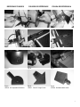
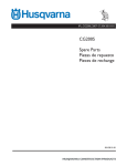
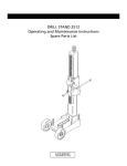
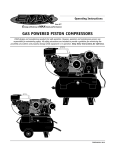
OPERATING INSTRUCTIONS AND PARTS LIST
INSTRUCTIONS D’UTILISATION ET LISTE DE PIÈCES
INSTRUCCIONES DE OPERACIÓN Y LISTA DE PIEZAS
TM-75 Tile Saw
17400 West 119th Street
Olathe, Kansas 66061
Customer Service ......800-365-4003
Corp. Office ...............913-928-1000
Cust. Service FAX......800-825-0028
Corp. Office FAX .......913-438-7951
0AF04107
© Copyright, August 20, 2004,
Electrolux Construction Products
EVERY MACHINE IS THOROUGHLY TESTED BEFORE LEAVING THE FACTORY. EACH MACHINE IS
SUPPLIED WITH A COPY OF THIS MANUAL. OPERATORS OF THIS EQUIPMENT MUST READ AND BE
FAMILIAR WITH THE SAFETY WARNINGS. FAILURE TO OBEY WARNINGS MAY RESULT IN INJURY OR
DEATH. FOLLOW INSTRUCTIONS STRICTLY TO ENSURE LONG SERVICE IN NORMAL OPERATION.
CONTENTS
Symbol Definitions .................................................................................................................................3 - 4
Decal Descriptions and Locations..........................................................................................................5
Reference Figures. ................................................................................................................................6 - 7
Safety Warnings – DO’s & DO NOT’s ...................................................................................................8 - 9
Instructions
1. Features ....................................................................................................................................10
2. Benefits .....................................................................................................................................10
3. Machine Set-Up ........................................................................................................................11 - 12
4. Operating Procedures..............................................................................................................12 - 13
5. Alignment Procedures ………………………………………………………………………………. 13
6. Maintenance..............................................................................................................................14
7. Trouble Shooting Guide………………………………………………………………………………15
8. Repairs......................................................................................................................................15
9. Spare Parts ...............................................................................................................................15
Diagrams and Spare Parts.....................................................................................................................16 - 17
Warranty ................................................................................................................................................19
WARNING
HEARING HAZARD
DURING NORMAL USE OF THIS MACHINE, OPERATOR MAY BE EXPOSED TO A
NOISE LEVEL EQUAL TO OR SUPERIOR TO 85 dB (A)
ATTENZIONE!!!
RISCHIO DE LESIONE ALL’APPARATO UDITIVO
NELLE NORMALI CONDIZIONI DI UTILIZZO,
QUESTA MACCHINA PUÒ COMPORTARE PER L’OPERATORE ADDETTO UN ESPOSIZIONE
ACUSTICA DI LIVELLO PARI O SUPERIORE A
85 dB (A)
ATENCION
RIESGO DE DAÑO AUDITIVO
EN CONDICIONES NORMALES DE UTILIZACIÓN, EL OPERADOR DE ESTA MÁQUINA PUEDE
ESTAR EXPUESTO A UN NIVEL DE RUIDO IGUAL O SUPERIOR A 85 dB (A)
2
Symbols Definitions
Symboles
Definición De Simbolos
• Please read the instructions for use prior to operating the machine for the first time.
• Avant toute mise en service, lire attentivement la notice et se familiariser avec la machine.
• Antes de la puesta en marcha, lea detenidamente las instrucciones y familiaricese con la máquina.
• Mandatory
• Obligatoire
• Obligatorio
• Indication
• Indicazione
• Indicación
• Prohibition
• Interdiction
• Prohibición
• Warning Triangle
• Triangle d’advertissement
• Triángwulo De Advertencia
• Wear Eye Protection
• Port obligatoire des lunettes de protection
• Usar Gafas De Protección
• Wear Breathing Protection
• Port obligatoire d’un masque respiratoire protecteur
• Usar Máscara De Protección
• The Use Of Ear Protection Is Mandatory
• Port obligatoire da casque antibruit
• Es Obligatorio El Uso De Protección Auditiva
• Wear Safety Shoes
• Port obligatoire des chaussures de sécurité
• Usar Zapatos De Seguridad
3
• Wear Appropriate Clothing
• Port obligatoire de la tenue appropriée
• Usar Ropa Adecuada
• Machinery Hazard, Keep Hands And Feet Clear
• Danger! Rester à distance de la machine
• Máquina Peligrosa - Mantenga Manos Y Pies Alejados De La Máquina
• No Non-Working Personnel In Area
• Zone interdite au personnel non-ouvrier
• Prohibido Para Personas Ajenas A La Obra
• Keep Work Area Clean/Well Lit, Remove All Safety Hazards
• La zone de travail doit toujours être propre, bien éclairée et ne présenter aucun risque
• Mantenga Limpio El Sitio De Trabajo/Bien Iluminado, Elimine Todos Los Riesgos De Seguridad
• Dangerously High Noise Level
• Niveau de bruit dangereux
• Nivel De Ruido Elevadamente Peligroso
• Repairs Are To Be Done By An Authorized Dealer Only
• Les réparations ne peuvent être exécutées que par un distributeur agréé
• Las Reparaciones Deben Ser Efectuadas Únicamente Por Un Distribuidor Autorizado
• Always Keep the Blade Guards In Place
• Toujours vérifier que les protections de disque sont bien en place
• Mantenga siempre las protecciones de la hoja en su sitio
• Diamond Blade
• Disque diamanté
• Sierra Diamantada
• Electrical Shock Hazard
• Risque de secousses électriques
• Peligro de sacudida eléctrica
4
DECAL DESCRIPTIONS & LOCATION
AUTOCOLLANTS – DESCRIPTIONS ET EMPLACEMENTS
DESCRIPTIÓN DE CALCAMONIAS Y UBICACIONES
P/N 185262
Location: Tray - Front
P/N 169866
Location: Rip Guide
P/N 185263
Location: Motor Cover - Front
P/N 185264
Location: Blade Guard - Side
P/N 187043
Location: Motor Cover - Top
P/N 189247
Location: Motor Cover - Rear
5
REFERENCE FIGURES
FIGURES DE RÉFÉRENCE
FIGURA DE REFERENCIA
Fig 1
Fig 2
Fig 3
Fig 4
Fig 5
Fig 6
Fig 7
Fig 8
Fig 9
Fig 10
6
Fig 11
Fig 12
REFERENCE FIGURES
FIGURES DE RÉFÉRENCE
FIGURA DE REFERENCIA
Fig 13
Fig 14
Fig 15
Fig 16
Fig 17
Fig 18
Fig 19
Fig 20
Fig 21
Fig 22
187076 90° Adjustable Protractor
Fig 23
187077 Dual 45° Angle Guide
Fig 24
187078 Bull Nose Miter Guide
7
SAFETY FIRST!
WARNINGS
DO’s AND DO NOT’s
WARNING: FAILURE TO COMPLY WITH THESE WARNINGS AND OPERATING
INSTRUCTIONS COULD RESULT IN DEATH OR SERIOUS BODILY INJURY.
DO
DO
DO
DO
DO
DO
DO
DO
DO
DO
DO
DO
DO
DO
DO
DO
DO
DO
DO
DO
DO
DO
DO
DO
DO
DO
DO
DO
DO
DO
DO
DO
DO
DO
DO
DO
DO
DO
DO
8
read this entire operator’s manual before operating this machine. Understand all warnings, instructions, and controls.
keep all guards in place and in good condition.
wear safety approved hearing, eye, head and respiratory protection.
read and understand all warnings and instructions on the machine.
read and understand the symbol definitions contained in this manual.
keep all parts of your body away from the blade.
know how to stop the machine quickly in case of emergency.
turn the “ON/OFF” switch to the “OFF” position prior to connecting the machine to the power source.
inspect the blade, flanges and shafts for damage or dirt before installing the blade.
always keep children away from this machine.
use only blades marked with a maximum operating speed greater than the blade shaft speed.
always use a ground fault circuit interrupter when wet sawing.
read all safety materials and instructions that accompany any blade used with this machine.
inspect each blade carefully before using it. If there are any signs of damage or unusual wear, DO NOT USE THE
BLADE.
mount the blade solidly and firmly. Wrench tighten the arbor nut.
use the correct blade for the type of work being done. Check with blade manufacturer if you do not know if blade is
correct.
operate this machine only in well ventilated areas.
establish a training program for all operators of this machine.
clear the work area of unnecessary people. Never allow anyone to stand in front of or behind the blade while the motor
is running.
make sure the blade is not contacting anything before starting the motor.
use caution when lifting and transporting this machine.
always tie down the machine when transporting.
use caution and follow instructions when setting up the machine.
have all service performed by competent service personnel.
make sure electric powered machines are plugged into a properly grounded circuit.
make sure power cords are the proper size and in good condition.
maintain a secure grip on the material being cut.
verify the blade arbor hole matches the machine spindle before mounting the blade.
clean the machine after each day’s use.
follow all electrical codes in your area.
consider work area environment. Don’t expose power tools to rain. Don’t use power tools in wet locations.
use caution to guard against electric shock. Prevent body contact with grounded surfaces (i.e., pipes, radiators,
ranges, refrigerators).
use correct voltage and proper extension cords. Never carry tool by cord or yank it to disconnect it from receptacle.
Keep cord away from heat, oil and sharp edges.
always carry the machine with the motor stopped and power cord disconnected.
disconnect tools from power source when not in use, before servicing and when changing accessories.
carefully maintain and clean for better and safer performance. Follow instructions for changing accessories. Inspect
tool cords periodically and, if damaged, have repaired by authorized service facility.
only cut in a straight line.
always give a copy of this manual to the equipment user. If you need extra copies, call TOLL FREE 1-800-365-4003.
SAFETY FIRST!
WARNINGS
DO’S AND DO NOTS
WARNING: FAILURE TO COMPLY WITH THESE WARNINGS AND OPERATING
INSTRUCTIONS COULD RESULT IN DEATH OR SERIOUS BODILY INJURY.
DO NOT
DO NOT
DO NOT
DO NOT
DO NOT
DO NOT
DO NOT
DO NOT
DO NOT
DO NOT
DO NOT
DO NOT
DO NOT
DO NOT
DO NOT
DO NOT
DO NOT
DO NOT
DO NOT
DO NOT
DO NOT
DO NOT
DO NOT
DO NOT
DO NOT
DO NOT
DO NOT
DO NOT
DO NOT
DO NOT
DO NOT
DO NOT
operate this machine unless you have read and understood this operator’s manual.
operate this machine without the blade guard, or other protective guards in place.
stand behind or in front of the blade path while the motor is running.
leave this machine unattended while the motor is running.
work on this machine while the motor is running.
operate this machine when you are tired or fatigued.
use a wet blade without adequate water supply to the blade.
exceed maximum blade speed shown for each blade size. Excessive speed could result in blade breakage.
operate the machine if you are uncertain of how to run the machine.
use damaged equipment or blades.
touch or try to stop a moving blade with your hand.
cock, jam, wedge or twist the blade in a cut.
use a blade that has been dropped or damaged.
use carbide tipped blades.
use abrasive blades.
touch a dry cutting diamond blade immediately after use. These blades require several minutes to cool
after each cut.
use damaged or worn blade flanges.
allow other persons to be near the machine when starting or when the machine is in operation.
operate this machine in an enclosed area unless it is properly vented.
operate this machine in the vicinity of anything that is flammable. Sparks could cause a fire or an
explosion.
allow blade exposure from the guard to be more than 180 degrees.
operate this machine with the blade guard removed.
operate this machine unless you are specifically trained to do so.
use a blade that has been over heated (Core has a bluish color).
jam material into the blade.
grind on the side of the blade.
lay power cords in or near the water.
replace the motor with any motor that does not have a special grounding connection.
stand or lean on machine.
start cutting with a saw until you have a clear work area and secure footing.
operate this machine while using drugs or alcohol.
*****************
This saw was designed for certain applications only. DO NOT modify this saw or use for any application
other than for which it was designed. If you have any questions relative to its application, DO NOT use the
saw until you have written Electrolux Construction Products and we have advised you.
Electrolux Construction Products
17400 West 119th Street
Olathe, Kansas 66061
1-800-365-4003
9
MANDATORY
INDICATION
INFORMATION
INSTRUCTION
WARNING
PROHIBITION
These signs will give
advise for your safety
Before leaving our factory every machine
is thoroughly tested.
Follow our instructions strictly and your machine
will give you long service in normal operating
conditions.
1.
Features
Use:
Sawing of tile materials.
Tools: Diamond blades -(For information contact your FELKER® supplier)
Blade Capacity: Ø 8″ (200 mm) – bore 5/8″
(15.9 mm).
Blade Rotation: Counter-Clockwise (CCW).
Cutting Thickness (material): 1 5/8″ (41.2mm)
Cutting Diagonal @ 10″ (254mm)
Cutting Length: 14″ (356mm)
Blade Cooling: Water pump
Horsepower:
Voltage:
3/4
115 Volts, 60 Hertz, 1-Phase
Amperage:
4.2 amps
Blade Shaft RPM: (3300)
Weight lbs. (kg.): 36.5 (16.5)
Dimensions (L x W x H): 26″ x 16.5″ x 14″
(660 x 419 x 356mm)
Pan Holding Capacity: 9.3 quarts (8 liters)
Before starting up the machine, make sure
you read this entire manual and are familiar
with the operation of this machine.
The working area must be completely clear,
well lit and all safety hazards removed.
The operator must
wear protective
clothing appropriate
to the work he is
doing.
10
Any persons not involved in the work
should leave the area.
Use only blades marked with a maximum
speed greater than the blade shaft
speed.
2.
Benefits
Your FELKER® tile saw is a ruggedly constructed unit
engineered to give long, satisfactory performance.
Simple, daily maintenance and care will add to the life
and productivity of your tile saw.
• Light weight for easy maneuverability and
maintenance.
• Has a durable polymer cutting table – able to
handle almost any cutting job due to its reinforced
construction.
• Cutting table designed to drain water quickly back
into the water tray for efficient recycling of water.
• Cast blade guard with hinge to allow easy
removal of cutting blade.
• Cutting table runs on nylon wheels for smooth
and accurate cuts and easy maintenance.
• Water tray of durable polymer construction to
resist rust and to drain water and sediment much
faster.
3.
Machine Set-Up
WATER PUMP SAFETY GUIDELINES AND
MAINTENANCE.
Follow all of the assembly and
installation instructions completely
before connecting this saw to a power
source.
UNPACKING
(Fig’s. 1, 2 & 3)
Carefully open the container and remove all the saw
components and packing materials. Be certain you
have checked each item with the checklist below
before discarding the container or the packing
materials. The contents are as follows:
1. Operator’s Manual
2. Durable Water Tray
3. Saw Frame w/Cart
4. Power Head
5. Blade Guard
6. Cutting Guides (4)
7. Water Pump w/ Hose
8. Blade - 8” [200 mm]
9. Misc. Tools & Hardware
NOTE: IF ANY OF THE PARTS ARE MISSING OR
DAMAGED PLEASE CONTACT YOUR FELKER
CUSTOMER SERVICE FOR INSTRUCTIONS.
CALL 1-800-365-4003
ASSEMBLY
• Assembly Tools required:
- four wrenches supplied (2 allen type)
• Place saw frame with cart into water tray. (Fig 4)
• Feed the powerhead assembly onto the arm of the
saw frame through the opening in the back of the
powerhead. (Fig 5)
• Allign the three holes in the powerhead with the
three threaded holes in the saw frame arm and
install the M5 x 10mm capscrews and lock
washers. (Fig 6)
• Loosely Install the M6 x 40mm capscrew and
washers at the rear of the saw frame. Insert just
enough brass spacers to fill any gap between the
saw frame and the powerhead, and then fully
tighten the capscrew. Not using spacers can
adversely affect allignment. (Fig 7)
• Install blade guard onto the powerhead with
supplied knob. (Fig 8)
WATER PUMP INSTALLATION
• Remove the water pump from its packaging and
check it to be sure it is not cracked or damaged in
any way.
• Route the 8mm plastic tubing as shown. (Fig 9)
• Attach the ends of the 8mm plastic tubing to the
blade guard and to the water pump. (Fig 10 & 11)
• Place the water pump in the rear of the water tray
and set in place using the mounting bracket as
shown. (Fig 12)
• Keep the power cord out of the water and plug into
the motor pigtail three-pronged outlet. (Fig 16)
Always plug the saw power cord into a
GFCI outlet when using. If a GFCI type
outlet is not available, use a plug-in type
GFCI plugged into a properly grounded
outlet. Do not use any temporary plug
adapters.
•
•
•
•
•
•
•
The water pump is equipped with a ground
electrical plug, to reduce the risk of possible
shock. Be sure to connect to a properly grounded
type receptacle.
Never pick the water pump up out of the water
when it is plugged in.
DO NOT EVER use the water pump to pump
anything but water.
Never service the pump when it is still plugged in.
Never let the pump operate dry. It is self-cooled
by pumping water. Dry use will cause the pump to
fail.
Maintain regularly and clean out debris from intake
screen.
Check the power cord for nicks or frays and never
try to alter the power cord in any way.
FITTING OR CHANGING THE BLADE
BLADE INSTALLATION AND REMOVAL
(Fig 13-15)
•
•
•
•
•
•
•
Turn motor switch off.
Disconnect power cord.
Carefully raise the blade guard to its highest
position and tighten the adjustment knob on the
rear support, so as to put firmly in place.
Then remove the blade shaft nut and the outer
flange. (Fig 13) Use the 5mm allen wrench to hold
the shaft and the box end wrench to turn the nut
counter-clockwise. (Fig 15)
Place blade onto the shaft, pushing it up against
the inner flange. Make sure the blade is mounted
with the directional arrow pointing counterclockwise. (Fig 14)
Next replace the outer flange and shaft-nut and
tighten down. (Fig 14, 15) Do not over-tighten.
Next lower the blade guard back into position and
tighten the knob.
Pay attention to the direction of rotation
shown by the arrow on one side of the
Blade (rotation in the opposite direction
to the tightening of the nut). Blade should
rotate counter-clockwise when facing the
bladeshaft nut.
11
Make sure that the supporting surfaces of
the Blade, the Flanges and the arbor are
clean.
ELECTRICAL CONNECTIONS
• Use a grounded circuit.
• Use a GFCI when wet sawing.
• Use the correct plug and outlet.
• Check that the main voltage is identical to that of
the machine.
• Extension cord: Use the correct size extension
cord. Be certain that the cord is in good service
condition.
• If, on position 1 (on), motor does not run:
check the electric power on the site (fuses,
cutouts, sockets, etc);
check the extension being used (faulty
connection, wire break)
check power cable, it’s connection;
check the operation of the on-off switch.
Before any examination, unplug the
machines power cord.
4.
Operating Procedures
•
•
•
•
•
•
Always be very careful.
Find a comfortable, well-balanced
position.
Always keep protective casing in
place while working.
Place the machine on a dry surface or the optional
stand.
Fill the holding tank with clean water [holds 9.3
quarts (8 liters).
Plug the machine into the power outlet and turn
the motor switch to the on position.
CUTTING TABLE
THE CUTTING TABLE IS MARKED IN INCHES AND
MILLIMETERS TO MAKE YOUR DIMENSIONAL
CUTS ACCURATE.
STEPS FOR POSITIONING THE 90 DEGREE RIP
• Slide the rip guide onto the table backstop from
one end. (Fig 17)
• Set the rip guide by positioning it at the desired
point on the front end of the cutting table front lip
and flipping down the thumb lock until the rip guide
is firmly locked in place. (Fig 18) Note that the
thumb lock will hold accessory firmly in place
without using the full travel of the thumb lock.
12
•
•
•
Additional movement is designed for any long
term wearing that may be experienced.
Unnecessary clamping with the thumb lock could
raise the end of the accessory up off the table
surface.
The rip guide can be used for straight 90° cuts
from both the left and right sides.
After the rip guide is positioned for the desired cut,
place material flush against the rip guide and the
measurement rail.
Now you are ready to make your cut.
CUTTING DEPTH
The 8” (200mm) blade capacity yields a cutting depth
of 1 5/8” (41,2mm).
After completing any work, switch off the
machine. There is no point in leaving the
motor running and the blade turning.
QUICK TIPS FOR WATER PUMP OPERATION
If you are having trouble getting water flow properly
through the water pump, try this:
• First, check to see that the pump is fully
submerged in water. Fill the water tray with clean
water to completely cover the pump.
• Second, check to see if all tubing is connected to
the pump correctly and its feeds are properly
attached.
Sometimes the tubing is not pushed far enough into its
attachment, allowing water to escape at the
attachment point. Simply push tubing firmly into fitting
until it stops and will not pull back out.
• Third, if there is a problem getting water to flow
out properly, check the water control valve setting
on the front of the pump. It can be adjusted from
“Min” to “Max” (Fig 19)
Often times the water control valve is set to “Min” and
is not capable of pumping enough water when first
turned on. This is easily corrected by turning the valve
to “Max” and then adjusting to the desired water flow.
• Fourth, if problems still persist, there is also a
chance that debris or sediment is clogging the
water pump intake screen, the pump impeller or
inside the tubing.
- Clearing these areas with fresh water can
alleviate the clogging. The build up sediment
needs to be cleaned from the bottom of the
Water Tray and the intake screen cleaned. Fill
tray with fresh water.
- With pump intake removed, look inside the
area impeller and check for debris. Clean as
needed with fresh water. (Fig 20)
- If the tubing is clogged, remove ends from the
water pump and Blade guard fitting. Flush
with fresh water until all debris is removed and
reconnect tubing. (Fig 10 & 11)
WATER TUBING REMOVAL (Fig’s 10, 11)
Plastic tubing connects the water pump to the blade
guard. The fittings used to connect this tubing seal and
grip the outside diameter of the tubing. Special internal
locking fingers attached to the flanged collet hold the
tubing fast. To clean the water tubing requires the
tubing to be removed from the fittings. To release the
tubing form the fitting, fully depress the collet before
pulling the tube out of the fitting. When you press
down on the collet you are opening the locking fingers
and freeing the tubing to be easily removed.
WATER TRAY REMOVAL AND INSTALLATION
THE REMOVAL AND INSTALLATION OF THE
WATER TRAY IS EASY.
• First turn off the saw and unplug the power cord.
Do the same for the water pump.
• Then remove water pump from tray.
• Then take frame and motor assembly out of the
water tray.
• Take tray and drain water and contents (sediment)
• To install simply reverse this process.
NOTE: THERE ARE NO ADJUSTMENTS TO WATER
TRAY
5.
Alignment Procedures
the fasteners. It is recommended that the
Parallel Alignment in step 2 be checked to
insure the best quality cuts.
2. Check the Parallel Alignment
• The conveyor cart should travel parallel to the
plane of the blade.
• Place a square rule against the backstop,
lightly in contact with the blade. The blade
surface should be parallel to the square; e.g.,
no gap between the blade and the square at
either the front or back edge of the blade.
Next, holding the square firmly traverse the cart
fore and aft. The blade should remain parallel
to the square, staying slightly in contact with it
throughout its full travel. If the blade does not
stay in contact with the square, the Parallel
Alignment must be performed.
Parallel Alignment (See Parts List, Diagram 1 &
Fig 21)
• Loosen the front two Roller Guide fasteners
(Item 6 & 8). Move the Roller Guide Bar (item
3) and Cart by the Adjustment Clamp (item 4)
until the square is flush with the blade. Tighten
the fasteners and recheck the alignment again.
The cart should now travel parallel to the blade
and the blade should be centered in the slot.
Your TM-75 tile saw is factory assembled and
aligned prior to shipment to ensure accurate cuts
when your saw is delivered. However, since FELKER
® cannot control rough handling during shipping, it is
suggested that the alignment be checked. If the saw
is found in need of adjustment, refer to the appropriate
section(s) below.
There are two basic TM-75 alignment checks. Any
adjustments made must follow these procedures to
ensure that the unit functions freely.
Adjustment tools required: Carpenter’s Square and
the small open-end wrench provided with your new
saw. (Fig 3)
1. Check the Blade in Slot Alignment
• The blade should be centered in the conveyor
cart slot.
• Set-up your saw as described above, move the
conveyor cart back and forth form the front to
the rear of the pan. If the blade contacts either
side of the slot, the Cart Slot Location
Adjustment must be performed.
Cart Slot Location Adjustment (See Parts List,
Diagram 1)
• Move the Conveyor Cart so the Blade is
approximately midway between the front and
back of Cart. Loosen the three (3) Roller Guide
fasteners (Items 6 & 8) with the supplied
wrench. Move the Adjustment Clamp (item 4),
Roller Guide Bar (item 3) and Cart together
until the blade is centered in the slot. Tighten
13
6.
Maintenance
Before performing any maintenance,
ALWAYS place the machine on a level
surface with the motor OFF and
disconnect the electrical current. Let
the machine cool down!!
FOR LONGEST LIFE AND BEST PERFORMANCE
• Always clean the saw after every use.
• Wipe all of the exterior sediment or dirt off the
motor. Never spray water directly onto the
motor!
• Wipe all exterior surfaces and keep the cutting
table clean and free of all debris.
• Wipe the roller guide bar on the frame.
• Always check the blade for cracks or signs of
damage.
OPTIONAL ACCESSORIES
Folding Stand:
- #187073 Stand with wheels
Store in a safe place, out of reach of
children.
Maintain all tools carefully.
14
7.
The manufacturer accepts no
responsibility caused by unsuitable use
or modifications. At the workstation, the
sound pressure level may exceed 85 dB
(A). In this case hearing protection must
be worn.
Trouble Shooting Guide
SAW WON’T START, SAW IS TOO SLOW TO
START, SAW MOTOR MAKES HUMMING NOISE
• Make sure plug is in live electrical circuit.
• Voltage from source may be too low.
8.
SAW SHUTS OFF ABRUPTLY
• Power is interrupted, check power source and
restart the saw.
• Voltage from source may be too low. Check for
low voltage.
WATER PUMP SYSTEM WON’T START OR STOPS
ABRUPTLY
• Check to see that pump is plugged in and is
connected to plastic tubing.
• Check to see if pump is completely submerged.
• Check to see if the water pump is clean and free
of any chips, debris, clogging, etc.
SAW WON’T CUT STRAIGHT
• Check to see if saw frame or rolling guide bar is
bent.
• Check to see if the support for the cutting table is
bent.
• Check for possible defective blade.
• Materials may have been pushed or forced
through the cut. Let blade pull material for a clean
cut.
• Check cart tracking adjustment.
SAW BLADE DOESN’T CUT WELL
• Blade needs to be dressed.
• Blade may be mounted on saw backwards.
• Blade may be worn or damaged.
• Blades life may be used up (old blade)
Repairs
Entrust all repairs to your authorized
dealer only.
We carry out all repairs in the shortest possible time
and at the most economical prices. (See front page
for our address and phone numbers) Contact your
authorized FELKER® dealer concerning maintenance
and repairs.
9.
Spare Parts
For quick supply of spare parts and to avoid any lost
time, it is essential to quote the data on the
manufacturer’s plate fixed to the side of the motor and
the part number(s) and description to be replaced with
every order.
The instructions for use and spare parts found in this
document are for information only and are not binding.
As part of our product quality improvement policy, we
reserve the right to make any and all technical
modifications without prior notice.
The manufacturer accepts no responsibility caused by unsuitable use or modifications.
15
DIAGRAM 1
16
DIAGRAM 1 --- TM-75 PARTS LIST
Loc
1
2
3
4
5
6
7
8
9
10
11
12
13
14
15
16
17
18
19
20
21
22
23
24
25
26
27
28
29
P/N
185108
185106
185107
185159
173019
167478
139746
185255
185111
185130
185136
185125
185126
185127
185137
139745
139737
185129
172027
185138
185131
173019
173059
139738
185245
185235
185260
185221
185216
Description
Frame Assy (incl. 2-8)
Frame
Bar, Roller Guide
Clamp, Roller Bar Adj.
Lockwasher, External Tooth, M8
Capscrew, Hex Hd M8 x 1.25 x 25mm
Washer, Flat M6
Screw, Mach Pan Hd M6 x 1.0 x 10mm
Water Tray
Assy, Cutting Table (incl. 11-24)
Cutting Table
Bracket, U Roller
Stud, Upper U Roller
Stud, Lower U Roller
Roller, U Shaped Nylon
Locknut, Fiber M6 x 1.0
Capscrew, Hex Hd M8 x 1.25 x 20mm
Bracket, Single Roller
Nut, Hex Hd M8 x 1.25
Roller, Right Side Nylon
Stud, Single Roller
Lockwasher, External Tooth, M8
Washer, Flat M8
Locknut, Fiber M8 x 1.25
Assy, Power Head w/ Guard (incl. 26-53)
Bracket, Motor Base Wldmnt
Plate, Spacer
Motor Assy, 3/4HP 4.2A 115V (incl. 29-35)
Spacer Sleeve (Before S/N 417841)
30
185215
Seal, Shaft (Before S/N 417841)
Qty
1
1
1
1
2
2
1
1
1
1
1
1
2
2
4
4
4
1
5
1
1
4
4
4
1
1
1
1
1
(See Note 1)
31
-32
33
34
35
36
37
38
39
40
41
42
43
44
45
46
47
48
49
50
51
52
(See Note 1)
185218 Flange, Inner (Before S/N 417841)
(See Note 1)
542190504 Flange, Inner (S/N 417841 & Later)
(See Note 1)
185219
185220
185248
185274
185239
185238
185214
185246
185247
020762
163689
185252
185253
090552
032503
173059
185258
020782
185259
172011
174432
Outer Flange
Nut, Arbor M12
Cover, Fan
Slinger, Shaft
Cover, Motor - Machined
Bushing, Strain Relief
Capacitor
Cord, 16/3 SJTW w/ Male Plug
Cord, 16/3 SJTW w/ Female Plug
Washer, Flat .250 SAE
Lockwasher, Split M6
Capscrew, Soc Bt Hd M6 x 1.0 x 16mm SS
Switch, Toggle 3/4hp
Plate, Switch
Shim, Brass .020
Washer, Flat M8
Capscrew, Soc Bt Hd M6 x 1.0 x 40mm SS
Lockwasher, Split #10
Capscrew, Soc Bt Hd M5 x 0.8 x 16mm SS
Nut, Hex Hd M5 x 0.80
Capscrew, Soc Hd M5 x 0.8 x 10mm
1
1
1
Loc
53
54
55
56
57
58
59
60
61
62
63
64
65
66
67
68
P/N
185243
185241
185150
185257
185140
185141
185244
020762
185251
185237
185160
185132
185146
185158
185201
169887
Description
Assy, Blade Guard (incl. 54-61)
Guard, Blade 8in - Machined
Adaptor - Y Water Tube
Tube, Water 6 x 4 x 280mm
Knob, M8 x 45
Screw, M4 x 20mm
Flap, Splash
Washer, Flat .250 SAE
Capscrew, Soc Bt Hd M6 x 1.0 x 10mm SS
Blade, 8in (200mm) Cont Rim
Bracket, Pump Mounting
Assy, Water Pump (incl. 65-66)
Water Pump 115V/60Hz
Adaptor, 90° Tube - Water Pump
Tube, Water 8 x 6 x 600mm
Guide, Rip - Plain
Qty
1
1
1
2
1
1
1
1
1
1
1
1
1
1
1
1
P/N
169866
185262
185263
185264
187043
189247
---- Items Not Shown ---Description
Decal, Felker Rip Guide
Decal, TM-75 Pan
Decal, TM-75 Motor Cover
Decal, Felker 8" [200mm] Guard
Decal, Warning
Decal, Water Pump Outlet
Qty
1
1
1
1
1
1
192001
185233
185145
185272
Wrench, Allen 4mm
Wrench, Allen 5mm
Wrench, Open [17 x 13]
Wrench, Box/Open [18 x 10]
187076 90° Adjustable Protractor
187077 Dual 45° Angle Guide
187078 Bull Nose Miter Guide
1
1
1
1
1
1
1
1
1
1
1
1
2
1
1
1
4
5
4
1
1
5
1
1
7
4
4
3
Note 1: Effective with Tile Saw Serial Number 417841 (Built August 16, 2004):
Inner Flange, P/N 542190504 Replaced Inner Flange, P/N 185218, Spacer, P/N 185216, and Seal, P/N 185215.
Outer Flange, P/N 542190504 can be used for units before Serial Number 417841, but Inner Flange (185218), Spacer (185216), and
Seal (185215) must be removed and discarded.
17
NOTES:
18
Felker’s New Equipment Warranty
Except as noted below. Felker warrants that its new equipment will be free from manufacturing defects for a
period of two (2) years from date of purchase by the original consumer purchaser.
The above warranty is subject to the following new equipment exceptions:
1. The warranty time period for the following new equipment is limited as follows:
TM-75™, FTS-150, FRS-30, FRS-38, FRS-51 --- One (1) year
FTS-70™, Little Jack, Jack Junior and Slammer Jack tools --- Six (6) months
FTS-50™ --- Ninety (90) days
2. To the extent the following components are part of any the new equipment, Felker’s warranty on the
component parts is limited to the manufacturer’s warranty period set out below:
Manufacturer.....Warranty Period
GAS and DIESEL ENGINES
Manufacturer.....Warranty Period
ELECTRIC MOTORS
Manufacturer.....Warranty Period
TRANSMISSIONS
Briggs & Stratton....................2 years
Koler Gas................................2 years
Robin Gas................ 2 yrs./2,000 hrs.
Honda Gas..............................2 years
Wiscinsin Gas..........1 year/2,000 hrs.
Hatz Diesel..............................1 year
Baldor.......................................1 year
Leeson......................................1 year
Bosch...................................6 months
Milwaukee............................Lifetime
Black & Decker........................1 year
DM100................................6 months
AIR MOTORS and VAC. PUMPS
Gast..........................................1 year
Eaton.....................................3 years*
Sunstrand................3 yrs./1,000 hrs.*
(* from date of manufacture)
HYDRAULIC PUMPS
Fenner-Stone............................1 year
John S. Barnes Co....................1 year
WATER PUMPS
Jasbsco.....................................1 year
Beckett.....................................1 year
3. Felker’s obligation under this warranty is expressly limited to the replacement or repair at Felker, Olathe,
KS 66061, or at a service facility designated by Felker, of such parts as inspection shall disclose to have been
defective. This warranty does not cover labor, except for gas powered Quickie Super saws and does not cover
maintenance items such as belts, air filters, bearings and wheels. Purchaser will be responsibile for paying for
shipping costs to and from the location where the equipment is to be repaired or replaced. Motors and engines
are to be serviced by the nearest factory authorized serice center. These service centers are designated by the
manufacturer of the engine/motor. Under no circumstances will Felker be responsible for incidental or
consequential damages.
4. Felker’s warranty does not apply to defects caused by damage, abuse, modifications, low voltage, acts of
God, unreasonble use, faulty repairs made by others or defects caused by failure to plrovide reasonable
maintenance. All warranties are void if the equipment or any of its components are altered or modified by the
purchaser, or of the product is used in a manner or with a blade not recommended by the manufacturer.
5. The forgoing express warranties are in lieu of all other warranties. FELKER EXPRESSLY DISCLAIMS
ALL OTHER WARRANTIES, INCLUDING, WITHOUT LIMITATION, THE IMPLIED
WARRANTIES OF MERCHANTABILITY AND FITNESS FOR A PARTICULAR PURPOSE.
Please record the Date of Purchase and the Serial Number of your saw in the space below. (The serial number
is located on the side of the motor.) When ordering service items, please have this information available.
Serial Number:
Date of Purchase:
Model Number:
Where Purchased:
For any missing, damaged or service items needed, DO NOT return to original store of purchase,
instead contact:
FELKER CUSTOMER SERVICE
Cust. Service Phone.....1-800-365-4003
Cust. Service FAX.......1-800-825-0028
19
Felker Corporate Office
17400 West 119th Street
Olathe, Kansas 66061
Customer Service ..................800-365-4003
Corporate Office ....................913-928-1000
Customer Service FAX ..........800-825-0028
Corporate Office FAX ............913-438-7951
Customer Service, Int’l...........913-928-1258
www.felkersaws.com
From the Electrolux Group. The world’s No.1 choice.
Felker Latin America, Mexico, Caribbean,
Central and South America
17400 West 119th Street
Olathe, Kansas 66061
Phone ....................................913-928-1255
FAX........................................913-438-7938
Felker Canada
17400 West 119th Street
Olathe, Kansas 66061
Customer Service ..................800-365-4003
Customer Service FAX ..........800-825-0028