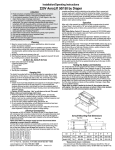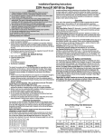
1
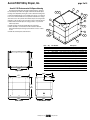
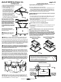
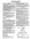
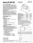
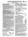
Installation/Operating Instructions
AeroLift 50/150 by Draper
Caution:
1 Read instructions completely before proceeding. Follow instructions carefully.
Installation contrary to instructions invalidates warranty.
2 Do not obstruct operation of AeroLift 50 or 150 with fingers or any other
object. Serious injury or damage could result.
3 It is not uncommon to overheat the motor during initial installation when
setting limits. The motor is thermally protected and will stop working
temporarily. DO NOT physically pull the unit down when this occurs. Once it
has cooled to a safe temperature, it will begin operating again.
4 The AeroLift 50 and 150 are designed to accommodate ceiling suspended
equipment. Equipment should not be allowed to rest on ceiling closures
during operation (see “Installing Projector”).
5 Entire bottom of unit must be unobstructed to permit proper operation.
6 Unit must be installed level (use a carpenter’s level).
7 Unit operates on 110-120V AC 60 Hz. current.
Note: Unit has been thoroughly inspected and tested at factory and found to be
operating properly prior to shipment.
Planning
1 Based on screen location and projector specifications, determine proper
position for projector installation.
2 Confirm that there is adequate space for installation and operation. Minimum
clearance above ceiling level varies according to height of projector, projector
mounting bracket, optional ceiling closure and optional Environmental Air
Space Housing.
3 Arrange to provide service access to the unit.
4 Total maximum capacity of AeroLift 50 is 50 lbs.; capacity for AeroLift 150 is 150
lbs. (including closure, projector and bracket).
As Soon As AeroLift Arrives
1 Open carton and inspect for damage.
2 Locate the following parts:
A. The unit itself
B. Controls
C. Any optional equipment
3 Test lift prior to installation.
to power supply and to switches should be furnished by installer. Connections
should be made in accordance with wiring diagram, and wiring should comply with
national and local electrical codes. All operating switches should be “off” before
power is connected. AeroLift should be operated and checked prior to installing
projector and/or optional ceiling closure.
Operation
When unit is first operated, be cautious! If unit fails to operate when the switch
is flipped “down”, return switch to “off” and re-check electrical connections
before proceeding. Cycle unit down and up several times to confirm satisfactory
operation.
110-120V Single Station Control—3-position up-off-down switch permits
operation to be stopped at any point. Factory adjusted limit switches automatically
stop AeroLift when fully down or fully up.
Optional 110-120V Multiple Station Control—Switches are similar in
appearance to 110-120V Single Station Control. AeroLift stops when switch is
released and may be restarted in either direction. Factory adjusted limit switches
automatically stop AeroLift when up or fully down.
Optional 24V Control—Three-button up-stop-down switches stop at any point
desired, operate in any sequence. Factory adjusted limit switches automatically
stop AeroLift when fully up or fully down.
Optional Infrared or Radio Frequency Remote Control—If ordered, a threebutton transmitter is provided, with “up”, “down” and “stop” buttons. Unit starts up
or down when appropriate button is pressed, and may be stopped by pressing
“off” button. Factory set limit switches stop unit automatically when projector is in
“show” position. Multiple Station Control required for this option.
Optional RS232/Ethernet—Serial communication and network communication
optionally available with wall switches, RF or IR remote.
Optional Key Operated Switching — Two kinds of key-operated switches
are optionally available with this unit. 1 The key-operated power supply switch
controls power to the AeroLift 25 and switches. When it is “off”, the switches will
not operate lift. Key may be removed from the switch in either “on” or “off” position.
2 A three-position key switch permits the AeroLift 25 to be operated directly by
key. In this case, the screen’s operator must always have a key.
Testing the Safety Limit Switches
Hanging Unit
The AeroLift is provided with four (4) mounting angles for suspending or direct
mounting the unit from above, or direct mounting from the sides. These angles
provide up to 1½" of adjustment (side to side). The unit should be guy wired or
blocked to prevent swinging. All installations should observe the following
guidelines:
1 Installer must ensure that all fasteners and supports are of adequate strength to
securely support AeroLift 50/150 and projector. It is recommended that
hardware structure be able to hold at least four times the combined weight of
the lift, projector, housing, closure and ceiling material attached to closure.
Caution: DO NOT hang from, "ride" or pull down on the unit. This could
create a failure and cause damage and/or injury.
2 Fastening methods must be suitable for mounting surface, and securely
anchored so vibration or abusive pulling on unit will not weaken installation.
3 Bottom of unit must be unobstructed after installation. Sufficient clearance must
be allowed below projector or optional ceiling closure.
4 Do not use unit to support adjacent ceiling, light fixtures, etc.
5 Do not complete the ceiling below the unit until electrical connections have
been completed and unit has been operated successfully.
6 Use slots on the projector plate and on the closure to adjust the unit to ensure
proper alignment of ceiling closure relative to ceiling opening.
The AeroLift 50 and 150 are equipped with two Safety Limit Switches (see "AeroLift—Limit Switch Adjustment (Bottom View)" diagram on page 3). These switches
may be damaged during shipping or by rough handling on the job site. Once the
AeroLift has been installed in the ceiling, but before the projector and closure are
attached, the Safety Limits must be tested. Use a screwdriver or other tool to
press and hold the limit switch. While holding down the limit switch, have someone
operate the unit. If the unit runs up while the limit switch is depressed, the
limit switch is broken and must be replaced. Operating the unit without a functioning Safety Limit Switch could cause the unit's motor to continue operating after
the lift is closed, leading to a failure and the possibility of damage or injury. Make
sure to test BOTH switches.
Please Note: As weight is applied to the AeroLift, the projector plate may
shift slightly. If this occurs, use setscrews on bottom of fabric roller brackets
to compensate for shift and level projector plate (see page 3).
Electrical Connections
Unit operates on 110-120V, 60 Hz. AC current. The AeroLift 50 and 150 are
shipped closed, with a temporary field connection provided in the form of a pigtail
temporarily wired to the unit. After hanging the unit, make sure power is off and
use this pigtail to temporarily connect the unit to power and to a switch, so the unit
can be lowered to allow access inside.
Please note: Make sure electrical supply has been disconnected before
attempting to connect AeroLift to electricity.
Terminal strip for field connections is located inside a junction box on the end of
the unit. Unit is shipped with internal wiring complete to the terminal strip. Once
the unit has been lowered, turn off power and remove the J-box cover. The
terminal strip is attached to the cover. Disconnect temporary pigtail from unit, then
complete permanent wiring to electricity and to switches. Wire to connect unit
AeroLift Mounting Hole Dimensions
Top View
Side View
A
E
B
C
F
D
Copyright © 2015 Draper Inc.
Form AeroLift50-150_Inst15
Printed in U.S.A.
Lift
A
B
C
D
E
F
AeroLift 50
28¼"
15"-13½"
10¾"-12¼"
26½"
26¾"
6"-44½"
AeroLift 150
31¼"
143/8"-177/8"
115/8"-131/8"
29½"
29¾"
6"-44½"
If you encounter any difficulties installing or servicing your AeroLift 50 or 150, call
your dealer or Draper, Inc. in Spiceland, Indiana, 765-987-7999 or fax 765-987-7142.
AeroLift 50/150 by Draper, Inc.
page 2 of 5
AeroLift 50 Environmental Air Space Housing
The Environmental Air Space Housing is shipped in pieces, and must
be assembled by the installer. The height of the Environmental Air Space
Housing can be adjusted by moving the screws to different mounting holes
in side panels. Aluminum tape (not provided) can be used to cover unused
holes. It is recommended that an access panel be installed in the ceiling to
allow future access. The optional environmental air space housing must be
installed to isolate the lift from the “other space used for environmental air.”
1 Attach Environmental Air Space Housing top frame to top of AeroLift
with bolts provided.
2 Install top panel to Environmental Air Space Housing frame.
3 Attach assembly to overhead structure. Allow clearance between
Environmental Air Space Housing top and structure for ease of future
access.
4 Install side and end panels, and trim frame.
9
10
8
8
6 5
2
1
3
4
5 6
6 5
1
2
6 5
6 7
12 14 13
27½"
225/8"
Top View
151/8"
30¼"
11
Item Qty Part Number
Description
1
4
C044.193SA
Panel, B Environmental Air Space Housing Side
2
4
C044.191SA
Panel, B Environmental Air Space Housing End
3
2
C044.192SA Panel, B Environmental Air Space Housing Middle Side
4
2
C044.190SA Panel, B Environmental Air Space Housing Middle End
5
28
C020.325
Screw, 8-32 X 3/8" Type 1 HWH
6
40
C018.051
Nut #8-32 Zinc Hex Keps
7
12
C013.070
Washer, .188 I.D. x .5 O.D. x .07 TK Nylon Flat
8
26
C020.112
Screw, 8-32 X 3/8" Type E F HWH
9
1 C028.609.01SA
Frame, B Environmental Air Space Housing
10
1
C095.130SA
Cover, B Environmental Air Space Housing
11
1 C028.610.07SA
Frame, B Trim Ring
12
4C013.024
Washer, 3/8" Flat
3
13
4C018.044
Nut, /8"-16 Zinc Hex Keps
14
4C020.313 Screw, 3/8"-16 x 1" GR 5 Zinc Hex Head Cap
297/16"
53/16"
Installing Optional Ceiling Finish Kit
The AeroLift is available with a ceiling finish kit, which
consists of the lower section of the Environmental Air Space
Housing (trim frame) and the closure panel.
1 Install AeroLift as previously described in these instructions.
2 Install trim frame in opening. This can be accomplished by
suspending with wire or mounting directly to ceiling joists (if
space permits).
3 Install projector and attach optional ceiling closure panel to
AeroLift (see page 3).
16"
to
365/8"
Ceiling Finish Kit
30¼"
30¼"
Front/Back View
Side View
Lower section of
Plenum Housing
Ceiling
(by oth tile
ers)
www.draperinc.com
(765) 987-7999
AeroLift 50/150 by Draper, Inc.
page 3 of 5
AeroLift 150 Environmental Air Space Housing
The Environmental Air Space Housing is shipped in pieces, and must
be assembled by the installer. The height of the Environmental Air Space
Housing can be adjusted by moving the screws to different mounting holes
in side panels. Aluminum tape (not provided) can be used to cover unused
holes. It is recommended that an access panel be installed in the ceiling to
allow future access. The optional environmental air space housing must be
installed to isolate the lift from the “other space used for environmental air.”
1 Attach Environmental Air Space Housing top frame to top of AeroLift
with bolts provided.
2 Install top panel to Environmental Air Space Housing frame.
3 Attach assembly to overhead structure. Allow clearance between
Environmental Air Space Housing top and structure for ease of future
access.
4 Install side and end panels, and trim frame.
9
14 13 12
8
8
6 5
1
2
3
4
5 6
6 5
1
2
6 7
6 5
10
27¼"
31¾"
Item Qty Part Number
Description
1
4
C044.198SA
Panel, E Environmental Air Space Housing Side
2
4
C044.196SA
Panel, E Environmental Air Space Housing End
3
2
C044.197SA Panel, E Environmental Air Space Housing Middle Side
4
2
C044.195SA Panel, E Environmental Air Space Housing Middle End
5
28
C020.325
Screw, 8-32 X 3/8" Type 1 HWH
6
40
C018.051
Nut #8-32 Zinc Hex Keps
7
12
C013.070
Washer, .188" I.D. x .5" O.D. x .07" TK Nylon Flat
8
26
C020.112
Screw, 8-32 X 3/8" Type F HWH
9
1
C095.131SA
Cover, E Environmental Air Space Housing Top
10
1 C028.612.07SA
Frame, E Trim Ring
11
1 C028.611.01SA
Frame, E Environmental Air Space Housing Top
12
4C020.313 Screw 3/8"-16 x 1" GR 5 Zinc Hex Head Cap
13
4C013.024
Washer, 3/8" Flat
3
14
4C018.044
Nut /8"-16 Zinc Hex Keps
Top View
30¼"
395/8"
15"
53/16"
16"
to
365/8"
40¾"
Side View
30¼"
Front/Back View
www.draperinc.com
(765) 987-7999
AeroLift 50/150 by Draper, Inc.
Installing Projector
Draper’s optional Universal Projector Mount will hold up to 26 lbs.
1 Bolt projector to Universal Mount Arms.
2 Bolt Projector Pan with Universal Mount
into place on bottom pan.
3 Use center nut and spring-loaded bolts
to fine tune picture placement on
screen. If not using Draper’s Universal
Projector Mount, generally the video
projector should be suspended from
the bottom pan according to projector
7"
manufacturer’s instructions. If installing
with a small closure, maximum projector
size is 18" x 8¾" (width x length x
Environmental Air Space Housing height).
If installing with a large closure, maximum projector
size is 18" x 18" (width x length x Housing height).
Figure
The projector plate is not pre-drilled.
When drilling inital holes for mounting
2½"
projector, or if for any reason the hole
placement must be changed, completely
lower AeroLift 25 before attempting to
drill holes. When attaching projector
bracket to plate, make sure screws are
short enough that they do not touch the
motor/roller above the plate when lift is
closed.
Unit and projection system should be
operated, checked and adjusted as
necessary at this time (see below for limit
adjustment procedures).
12"
Installing Ceiling Closure
page 4 of 5
If your AeroLift 25 is equipped with a ceiling closure system, it can be used as is, or in
conjunction with a piece of existing ceiling tile.
Please refer to diagrams at right for these instructions.
1 If installing with ceiling tile, you may need to cut tile so overall dimensions are the
same as (or slightly less than) the closure panel. Place tile into trim frame. Lay
closure panel on top (back side) of ceiling tile, and tighten screws to hold in place.
2 If installing large closure, attach brackets to bottom of projector plate (see fig. 7).
3 Attach 5/16" threaded rods to slots in projector plate or brackets.
Caution: Make sure bolts and nuts attaching brackets to AeroLift are
completely tightened.
4 Run unit “up” until bottom pan stops at highest position. Mark position on 5/16" rods
even with ceiling level and cut rods to length (removing from pan if convenient).
5 Run unit “down” until bottom pan stops at “show” position.
6 Attach closure to lower end of 5/16" rods by slipping into four corner slots and secure
with nuts above and below slots.
7 Run unit “up” again to highest position. Measure distance by which panel fails to
reach required “closed” height for surrounding ceiling.
Caution: Make sure nuts are completely tightened.
8 Run unit “down” then re-adjust mounting of 5/16" rods in traveling grid to raise panel
required distance.
9 Test unit operation to confirm that panel will stop in closed position just before
touching ceiling.
Caution: DO NOT hang from, "ride" or pull down on the unit. This
could create a failure and cause damage and/or injury.
7"
PLEASE NOTE: Immediately upon completion of the surrounding ceiling, unit
should be operated to confirm that optional ceiling closure panel by Draper or
by others stops 1/8" short of touching ceiling in closed position. If closure panel
touches, the motor may continue operating after the lift is closed. If it continues
to cycle once the lift is closed, a failure may occur, making the unit descend
rapidly and causing damage and/or injury.
Warning: Keep fingers & other objects
away from ceiling closure when unit is
operating. Serious injury or damage can
result.
Adjustments
CAUTION: Be sure all switches are in “off” position before adjusting limit switches
2½"new adjustment is being tested.
Always be prepared to shut lift off manually when
Limit switches for the AeroLift 25 are preset at the factory. The “Up” (closed) limit switch
12" Once unit is
is set for fully closed. The “down” (show) limit switch is set for fully lowered.
in place, the “down” limit switch may need to be changed to stop the AeroLift 25 closer
to the ceiling (that is, to raise the “down” position). Limit switches are located on the end
of roller, and are accessible by removing the cover of the junction box at the left end of
the unit. To adjust the limit switches, use a 5/32" screwdriver/allen wrench.
AeroLift 50 with Ceiling
Closure Panel
AeroLift 150 with Ceiling
Closure Panel
Caution: It is not uncommon to overheat the motor during initial installation
when setting limits. The motor is thermally protected and will stop working until it
has cooled to a safe temperature before it will start operating again. DO NOT
physically pull the unit down when this occurs.
Adjusting “Down” (show) position — “Down” position may be adjusted by turning the
#1 limit switch adjustment socket. Turning the socket clockwise will stop the AeroLift 25
closer to the ceiling. Turning it counter-clockwise will cause the lift to stop at a lower point.
Adjusting “Up” (closed) position — Because the “up” (“closed”) position is preset at
the factory, Draper does not recommend changing this position using the limit switch.
The “up” position of the closure may be changed by changing the length of threaded
rod (see fig. 6). If necessary, however, “up” position may be adjusted by turning the #2
limit switch adjustment socket. Turning the socket counterclockwise creates a higher, or
more fully closed position. Turning it clockwise creates a lower ‘UP” (closed) position.
Caution: Make sure limit switch is set so that the AeroLift 25 motor is NOT still
running after the lift is closed. If it continues to cycle once the lift is closed, a
failure may occur, making the unit descend rapidly and causing damage and/or
injury.
Down Limit
Up Limit
Figure
For Additional Safety:
1 Be sure the nuts that attach the threaded rods to the closure are tight.
2 Wrap a plastic wire tie around the mounting tab and the threaded
rod at all four corners of the closure panel (see drawing).
Please Note: Do NOT use a paper-covered or similar wire
tie—use only plastic wire ties for maximum safety.
AeroLift Clearance
Figure
Caution: Make
sure there are
no obstructions
to the AeroLift's
operation
Figure
Fabric roller adjustment setscrews
(one on each roller)
Please Note: If load is off-center of pan, you may need to adjust the pitch of the
fabric rollers. One setscrew is provided on each end of both fabric rollers (see
above drawing). Use these to adjust roller pitch to keep entire fabric panel taut, so
load is evenly distributed. Use 1/8" hex key to adjust.
www.draperinc.com
/8" Min. clearance
1
(765) 987-7999
AeroLift 50/150 by Draper, Inc.
page 5 of 5
Wiring Diagrams
Single Station Control
Optional Multiple Station Control
Black ( Down)
UP
N
Green (Ground)
Red (Up)
Safety Up
Switch
White (Common)
MOTOR
Green (Ground)
Black (Down)
Safety
Up Switch
Red ( Up)
White (Common)
Motor
DN
Cap off with wire
nut and tape.
Single gang box by others
Min. 4" x 21/8" x 17/8" deep
N
UP
DN
Red
Blue
Single gang box by others
Min. 4" x 21/8" x 17/8" deep
Blue
Black
Black
Location of key
operated on-off
switch if furnished
Red
Blue
Red
Black
Red
Dashed wiring
by electrician
Blue
Black
Dashed Wiring
By electrician.
Location of key
operated 0n-off
switch if furnished.
To 110-120V Line
To 110 -120 Vac Line
Optional Lift Low Voltage (& Wireless) Control
Safety Up Switch
White-Neutral (Common) to lift & 110-120V AC
Red-to lift (directional)
Brown-to lift (directional)
Yellow-to 110-120V AC
Black-to 110-120V AC
Green-Ground
N
Up
Dn
White (Common)
Red (Up)
Black ( Down)
Green (Ground)
To 110 -120V AC Line
3 Button Wall Switch
DOWN
COM
UP
www.draperinc.com
(765) 987-7999
Dashed Wiring
By electrician.
Low voltage
wiring by others.
Location of key
operated 0n-off
switch if furnished.
Eye Port for IR Eye, RF Receiver or LED
Switch. If more than one of these three is
used with one LVC-III, a splitter is required.
Aux Port for connecting additional LVC-III modules
(up to six total-connect from Aux to Eye).
MOTOR