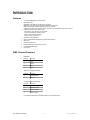
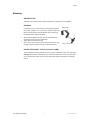
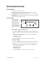
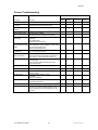
1
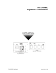
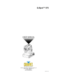
TFX-950CM Stage Wash™ 950 USER MANUAL Chauvet, 3000 N 29th Ct, Hollywood, FL 33020 U.S.A (800) 762-1084 – (954) 929-1115 FAX (954) 929-5560 www.chauvetlighting.com TABLE OF CONTENT BEFORE YOU BEGIN ...................................................................................................................................................... 3 WHAT IS INCLUDED................................................................................................................................................................................ 3 UNPACKING INSTRUCTIONS .................................................................................................................................................................... 3 AC POWER .......................................................................................................................................................................................... 3 SAFETY INSTRUCTIONS .......................................................................................................................................................................... 3 INTRODUCTION............................................................................................................................................................... 4 FEATURES ............................................................................................................................................................................................ 4 DMX CHANNEL SUMMARY ..................................................................................................................................................................... 4 PRODUCT OVERVIEW ............................................................................................................................................................................ 5 SETUP .............................................................................................................................................................................. 6 LAMP ................................................................................................................................................................................................... 6 POWER ................................................................................................................................................................................................ 6 MOUNTING ........................................................................................................................................................................................... 7 OPERATING INSTRUCTIONS.......................................................................................................................................... 8 OPERATING MODES .............................................................................................................................................................................. 8 Stand Alone Mode .................................................................................................................................................... 8 Master/Slave ............................................................................................................................................................ 9 DMX Mode ............................................................................................................................................................... 9 TFX-SWF Easy Controller (Optional) ...................................................................................................................... 11 TFX-CONPK Stage Wash™ Controller Pack (Optional).......................................................................................... 11 APPENDIX...................................................................................................................................................................... 12 DMX PRIMER ..................................................................................................................................................................................... 12 DMX CHANNEL VALUES ...................................................................................................................................................................... 13 RGB&D Mode (RGB and Dimmer).......................................................................................................................... 13 C&B Mode (Color and Brightness).......................................................................................................................... 13 RGB and Chase Mode............................................................................................................................................ 13 COLOR MIX TABLE (PRESET) ............................................................................................................................................................... 14 MAINTENANCE .................................................................................................................................................................................... 18 RETURNS PROCEDURE ........................................................................................................................................................................ 19 CLAIMS .............................................................................................................................................................................................. 19 GENERAL TROUBLESHOOTING.............................................................................................................................................................. 20 TECHNICAL SPECIFICATIONS ................................................................................................................................................................ 21 TFX-950CM User Manual 2 Revision: 2006-01-20/16:37 BEFORE YOU BEGIN What is included 1 x Stage Wash™ 950CM (TFX-950CM) Power cord with plug 3 x EHM 300w 120v or 3 x EHM2 300w 230v lamps Warranty Card & Manual Unpacking Instructions Immediately upon receiving a fixture, carefully unpack the carton, check the contents to ensure that all parts are present, and have been received in good condition. Notify the shipper immediately and retain packing material for inspection if any parts appear damaged from shipping or the carton itself shows signs of mishandling. Save the carton and all packing materials. In the event that a fixture must be returned to the factory, it is important that the fixture be returned in the original factory box and packing. AC Power To determine the power requirements for a particular fixture, see the label affixed to the back plate of the fixture or refer to the fixture’s specifications chart. A fixture’s listed current rating is its average current draw under normal conditions. All fixtures must be powered directly off a switched circuit and cannot be run off a rheostat (variable resistor) or dimmer circuit, even if the rheostat or dimmer channel is used solely for a 0% to 100% switch. Before applying power to a AC Voltage Switch fixture, check that the source voltage matches the fixture’s requirement. Check the fixture or device carefully to make sure that if a voltage selection switch exists that it is set to the correct line voltage you will use. Warning! Verify that the power select switch on your unit matches the line voltage applied. All fixtures must be connected to circuits with a suitable Earth Ground. Safety Instructions Please read these instructions carefully, which includes important information about the installation, usage and maintenance? Please keep this User Guide for future consultation. If you sell the unit to another user, be sure that they also receive this instruction booklet. Always make sure that you are connecting to the proper voltage and that the line voltage you are connecting to is not higher than that stated on decal or rear panel of the fixture. This product is intended for indoor use only! To prevent risk of fire or shock, do not expose fixture to rain or moisture. Make sure there are no flammable materials close to the unit while operating. The unit must be installed in a location with adequate ventilation, at least 50cm from adjacent surfaces. Be sure that no ventilation slots are blocked. Always disconnect from power source before servicing or replacing lamp or fuse and be sure to replace with same lamp source. Caution! Secure fixture to fastening device using a safety chain. Never carry the fixture solely by its head. Use its carrying handles. Maximum ambient temperature is Ta: 40°. Do not operate fixture at temperatures higher than this. In the event of serious operating problem, stop using the unit immediately. Never try to repair the unit by yourself. Repairs carried out by unskilled people can lead to damage or malfunction. Please contact the nearest authorized technical assistance center. Always use the same type spare parts. Don’t connect the device to a dimmer pack. Make sure power cord is never crimped or damaged. Never disconnect power cord by pulling or tugging on the cord. Avoid direct eye exposure to lamp while it is on. There are no user serviceable parts inside the unit. Do not open the housing or attempt any repairs yourself. In the unlikely event your unit may require service, please contact CHAUVET. TFX-950CM User Manual 3 Revision: 2006-01-20/16:37 INTRODUCTION Features 2-4 channel DMX RGB color wash fixture Operating modes: RGB Mode: Full RGB mix plus dimmer (4 channels) C&B Mode: Color selection (40 presets) and dimmer (2 channels) RGB & Chase Mode: 7 distinct operating modes (4 channels) - RGB mix, 8-pattern auto, 8-pattern sound, auto-chase, sound-chase, 40-color auto or sound Individual channel controls may include; - Red 0-100%, color selection or mode select - Green or Red 0-100%, dimmer 0-100% - Blue or Green 0-100%, fade time - Dimmer 0-100%, speed time 900 watts of total brightness Built in beat activated and automatic programs (stand-alone) Barn doors Sound sensitivity knob Double bracket yoke doubles as floor stand Linkable via Master/Slave Fan cooled DMX Channel Summary RGB Mode Channel Function 1 Red 2 Green 3 Blue 4 Dimmer C&B (Color & Brightness) Mode Channel Function 1 Color Selection 2 Dimmer Combined RGB & Chase Mode Channel Function 1 Control Mode 2 Red or Dimming 3 Green or Fade 4 Blue or Speed For complete channel listing see DMX Values in the Appendix section. TFX-950CM User Manual 4 Revision: 2006-01-20/16:37 Introduction Product Overview LED status window DMX channel values and brief instructions Control panel buttons DMX Input connector DMX Output connector TFX-950CM User Manual Fan Sound sensitivity knob Built in microphone IEC power connector for power cable Foot controller connector for TFX-SWF 5 Voltage Selector Switch Fuse compartment Revision: 2006-01-20/16:37 SETUP Lamp You will need to install a lamp prior to the initial operation of the fixture. Three EHM 300W halogen lamps are included. Warning! When replacing the lamp, please wait 15 minutes after powering down to allow the unit to cool down! Always disconnect from main power prior to lamp replacement. Do not touch the envelope (glass area) of the bulb with bare hands. If this happens, clean the lamp with alcohol and wipe it with a lint free cloth before installation. L AM P I N ST AL L AT I O N TFX-950CM Lamp Installation 1) Remove the 2 screws as illustrated in Figure 3, located on the front of the fixture and lift the entire cover plate until lamp reflectors are exposed. 2) The linear lamp is held in place by tension provided by springs inside of both ceramic socket ends. It is important to proceed with lamp removal and replacement very delicately. 3) Hold linear lamp with a napkin and push in the direction of either of the two ends to relieve tension on the opposite end. Then pull end of lamp upwards to remove from socket. 4) To replace lamp, follow the same procedure as above to insert lamp into the socket. 5) Lower the cover plate and replace both screws. 6) No lamp alignment is necessary for this fixture. Remove these 2 screws Lamps exposed Power Your product is equipped with switch-selectable AC power setting. Warning! Slide switch up or down depending on your line voltage. Verify that the power select switch on your unit matches the line voltage applied. All fixtures must be connected to circuits with a suitable Earth Ground. To determine the power requirements for a particular fixture, see the label affixed to the back plate of the fixture or refer to the fixture’s specifications chart. A fixture’s listed current rating is its average current draw under normal conditions. All fixtures must be powered directly off a switched circuit and cannot be run off a rheostat (variable resistor) or dimmer circuit, even if the rheostat or dimmer channel is used solely for a 0% to 100% switch. Before applying power to a fixture, check that the source voltage matches the fixture’s requirement. All fixtures must be connected to circuits with a suitable Earth Ground. TFX-950CM User Manual 6 Revision: 2006-01-20/16:37 Setup Mounting O RI E NT AT IO N This fixture may be mounted in any position provided there is adequate room for ventilation. RIG G ING Hanging Clamp It is important never to obstruct the fan or vents pathway. Mount the fixture using, a suitable “C” or “O” type clamp. Adjust the angle of the fixture by loosening both knobs and tilting the fixture. After finding the desired position, retighten both knobs. When selecting installation location, take into consideration lamp replacement access and routine maintenance. Safety cables should always be used. Never mount in places where the fixture will be exposed to rain, high humidity, extreme temperature changes or restricted ventilation. Note! Clamp is sold separately. DO U BL E BR AC K ET Y O K E ( F LO O R ST AN D) The TFX-950CM can also be positioned on the floor using its double bracket yoke. This product gets extremely hot under normal operation and you should take extreme care to avoid any contact what so ever with the fixture while in use. Be sure to keep all traffic at least 4 feet away from the fixture’s position. TFX-950CM User Manual 7 Revision: 2006-01-20/16:37 OPERATING INSTRUCTIONS Operating Modes The TFX-950CM can be operated in three ways. A stand-alone mode will listen to sound and run through its diverse range of built in programs. An optional TFX-SWF wired controller provides simple remote control. Master/Slave mode will allow the command of up to as many units you want in a synchronized light show to the sound. DMX control mode will provide the greatest flexibility and creativity. Each fixture trait can be controlled individually using any universal DMX-512 controller. Stand Alone Mode The Stand Alone mode is activated by setting the TFX950CM to either AUDIO (Sound Active) or AUTO (Automatic) mode. The built in programs consist of a color chase and depending on the mode, two or three parameters can be modified as described next. AUDIO DMX Signal Received F:0:0:0 MODE UP RGB&D C&B AUTO DOWN AU D IO M O DE ( AL SO SO UN D- ACT I V E) 1) A steady hold of the MODE button will change the operating mode once then release the button. 2) Repeat step 1 until you arrive at the AUDIO operating mode, as indicated by the LED next to the label. 3) Two parameters will now become available for the AUDIO mode. Press the MODE button quickly to toggle between parameters. - F (for Fade time 0 ~ 100%) - D (for Dimming 0 ~ 100%) 4) Use the UP and DOWN buttons to change values for each respective parameter. AUT O M AT I C M O D E 1) A steady hold of the MODE button will change the operating mode once then release the button. 2) Repeat step 1 until you arrive at the AUTO operating mode, as indicated by the LED next to the label. 3) Three parameters will now become available for the AUTO mode. Press the MODE button quickly to toggle between parameters. - F (for Fade time 0 ~ 100%) - D (for Dimming 0 ~ 100%) - S (for Speed 0 ~ 100%) 4) Use the UP and DOWN buttons to change values for each respective parameter. TFX-950CM User Manual 8 Revision: 2006-01-20/16:37 Operating Instructions Master/Slave The Master/Slave mode will allow you to link up to as many units you want in a daisy chain fashion. In this mode, the first unit in the daisy chain will automatically command all other units following. An optional TFX-SWF controller connected to the first unit in the chain will allow enhanced control functions. M AST E R/ S L AV E S ET T ING S 1) Connect the (male) 3 pin connector side of the DMX cable to the output (female) 3 pin connector of the first fixture. 2) Connect the end of the cable coming from the first fixture which will have a (female) 3 pin connector to the input connector of the next fixture consisting of a (male) 3 pin connector. Then, proceed to connect from the output as stated above to the input of the following fixture and so on as illustrated below in figure “Daisy Chain Connection”. Daisy Chain Connection Optional Controller Controller not required for Master/Slave operation Note! For additional information on linking fixtures read under section “DMX Primer” DMX Mode Operating in a DMX Control mode environment gives the user the greatest flexibility when it comes to customizing or creating a show. In this mode you will be able to control each individual trait of the fixture independently. S ET T ING T H E ST ART ING AD D R E SS This DMX mode enables the use of a universal DMX controller device. Each fixture requires a "start address" from 1 to 511. A fixture requiring one or more channels for control begins to read the data on the channel indicated by the start address. For example, a fixture that occupies or uses 6 channels of DMX and was addressed to start on DMX channel 100, would read data from channels: 100, 101, 102, 103, 104, and 105. Choose start addresses so that the channels used do not overlap and notate the start address selected for future reference. If this is your first time addressing a fixture using the DMX-512 control protocol than I suggest jumping to the Appendix Section and read the heading “DMX Primer”. It contains very useful information that will help you understand its use. There are three different DMX channel configurations on the Stage Wash. Each mode or configuration allows the user to control the fixure in a different manner using a universal DMX controller. AUDIO DMX Signal Received A:0:0:1 MODE TFX-950CM User Manual 9 UP RGB&D C&B AUTO DOWN Revision: 2006-01-20/16:37 Operating Instructions RG B &D M O DE All three lamps are individually dimmable giving the user the ability to customize or create the color of choice. This mode offers the user complete freedom. 1) A steady hold of the MODE button will change the operating mode once then release the button. Channel Function 1 Red 2 Green 3 Blue 4 Dimmer 2) Repeat step 1 until you arrive at the RGB&D operating mode, as indicated by the led next to the label. 3) The display will now read parameter A: which represents the DMX channel address value. Use the UP and DOWN buttons to change values. C& B M O DE This is called the Color and Brightness mode. Use channel 1 to move across the RGB spectrum. Channel Function 1 Spectrum Color Mix 2 Dimmer 1) A steady hold of the MODE button will change the operating mode once then release the button. 2) Repeat step 1 until you arrive at the C&B operating mode, as indicated by the led next to the label. 3) The display will now read parameter A: which represents the DMX channel address value. Use the UP and DOWN buttons to change values. See Color Mix Table in the appendix section. RG B & C H AS E M O D E This is the most diverse operating mode the Stage Wash has to offer. It allows individual RGB mix control when needed while still maintaining the ability to run built in automated chase programs. Channel Function 1 Control Mode 2 Red or Dimming 3 Green or Fade 4 Blue or Speed 1) A steady hold of the MODE button will change the operating mode once then release the button. 2) Repeat step 1 until both the RGB&D and the C&B led turn on. 3) The display will now read parameter A: which represents the DMX channel address value. Use the UP and DOWN buttons to change values. TFX-950CM User Manual 10 Revision: 2006-01-20/16:37 Operating Instructions TFX-SWF Easy Controller (Optional) The TFX-SWF Foot Controller is used only in master/slave mode. Connect the 8-pin connector of the foot controller into its respective connector on the first unit in the daisy chain. The table below describes the functions of the TFX-SWF Controller. TFX-SWF BUTTONS Stand By Mode Function Blackout Auto Led 1: Off Led 2: Off Fixtures will run built in programs automatically TFX-SWF Foot Controller TFX-SWF STAND-BY Audio Led 1: Off Led 2: On Fixtures will run built in programs to the sound. Manual Led 1: On Led 2: Off Full/CB: Hold: pedal to set to Full On Bump: Pedal to set dimming levels Manual Led 1: On Led 2: On Full/CB: Hold: pedal to set dimming levels Release: Pedal to set to Full On FUNCTION MODE TFX-CONPK Stage Wash™ Controller Pack (Optional) The TFX-CONPK is a package that includes the TFX-32CON which is an enhanced dedicated controller for the TFX-950CM, TFX-64CM and TFX-1550CM fixtures. The TFX-32F foot controller is also included for hands-free operation. The TFX-32CON provides the following features: 9 different hold-color buttons for immediate color access fader access to 40 predefined mixed colors fade time control 12 different chase patterns to choose from chase speed control master dimmer level blackout button full on button sound button T FX -3 2 CON The TFX-32F provides the following features: Selectable modes: 1. Blackout 2. Color Hold 3. Chase Up and down pedal buttons select colors and chase patterns TFX-32F Mode Please refer to the TFX-32CON and TFX-32F user manuals for more in depth information. TFX-950CM User Manual 11 Revision: 2006-01-20/16:37 APPENDIX DMX Primer There are 512 channels in a DMX-512 connection. Channels may be assigned in any manner. A fixture capable of receiving DMX 512 will require one or a number of sequential channels. The user must assign a starting address on the fixture that indicates the first channel reserved in the controller. There are many different types of DMX controllable fixtures and they all may vary in the total number of channels required. Choosing a start address should be planned in advance. Channels should never overlap. If they do, this will result in erratic operation of the fixtures whose starting address is set incorrectly. You can however, control multiple fixtures of the same type using the same starting address as long as the intended result is that of unison movement or operation. In other words, the fixtures will be slaved together and all respond exactly the same. DMX fixtures are designed to receive data through a serial Daisy Chain. A Daisy Chain connection is where the DATA OUT of one fixture connects to the DATA IN of the next fixture. The order in which the fixtures are connected is not important and has no effect on how a controller communicates to each fixture. Use an order that provides for the easiest and most direct cabling. Connect fixtures using shielded two conductor twisted pair cable with three pin XLR male to female connectors. The shield connection is pin 1, while pin 2 is Data Negative (S-) and pin 3 is Data positive (S+). CHAUVET carries 3-pin XLR DMX compliant cables, DMX-10 (33’), DMX-4.5 (15’) and DMX-1.5 (5’) F I XT UR E L I NK ING Figure 1 - DMX connector configuration 1 3 2 COMMON INPUT 1 3 2 1 3 2 DMX + OUTPUT DMX - Note! Resistance 120 ohm 1/4w between pin 2 (DMX -) and pin 3 (DMX +) of the last fixture. Termination reduces signal errors and to avoid signal transmission problems and interference, it is always advisable to connect a If you use a controller with a 5 pin DMX output connector, you will need to use a 5 pin to 3 pin adapter. Chauvet Model No: DMX5M. The chart below details a proper cable conversion: 3 Pin to 5 Pin Conversion Chart Conductor 3 Pin Female (output) 5 Pin Male (Input) Ground/Shield Pin 1 Pin 1 Data ( - )signal Pin 2 Pin 2 Data ( + ) signal Pin 3 Pin 3 Do not use Do not use Do not use Do not use TFX-950CM User Manual 12 Revision: 2006-01-20/16:37 Appendix DMX Channel Values RGB&D Mode (RGB and Dimmer) Channel Value Function 1 000 255 2 000 255 3 000 255 4 000 255 Red Intensity: 0% ~ 100% Green Intensity: 0% ~ 100% Blue Intensity: 0% ~ 100% Dimmer 0 100% Notes C&B Mode (Color and Brightness) Channel Value Function Notes 1 000 255 See Color Mix table on the next page 2 000 255 Spectrum Color Mix See Color Mix Table Dimmer Intensity: 0% ~ 100% RGB and Chase Mode Mode RGB Mode 8 Built-in Programs (Auto) 8 Built-in Programs (Sound) Chase (Auto) Chase (Sound) 40 Color Chase (Auto) 40 Color Chase (Sound) TFX-950CM User Manual Ch 1 (Mode) 000 029 030 094 Ch 2 Ch 3 Red: 0 ~ 100% Green: 0 ~ 100% 185 209 210 234 235 255 13 Blue: 0 ~ 100% Speed 094 159 160 184 Ch 4 Dimming: 0 ~ 100% Fade Time Speed Speed Revision: 2006-01-20/16:37 Appendix Color Mix Table (Preset) DMX Value Green Intensity 0% ~ 100% 0 Blue Intensity 0% ~ 100% 0 Notes 0 Red Intensity 0% ~ 100% 0 1 2 100 100 0 0 0 0 Red @ Full only 3 4 5 6 7 8 9 10 11 12 13 14 15 16 17 18 19 20 21 22 23 24 25 26 27 28 29 30 31 32 33 100 100 100 100 100 100 100 100 100 100 100 100 100 100 100 100 100 100 100 100 100 100 100 100 100 100 100 100 100 100 100 3 6 9 12 15 18 21 24 27 30 33 36 39 42 45 48 51 54 57 60 63 66 69 72 75 78 81 84 87 90 93 0 0 0 0 0 0 0 0 0 0 0 0 0 0 0 0 0 0 0 0 0 0 0 0 0 0 0 0 0 0 0 Red @ Full Proportional Green 34 100 100 0 Red & Green @ Full 35 36 37 38 39 40 41 42 43 44 45 46 47 48 49 50 51 52 53 54 55 56 97 94 91 88 85 82 79 76 73 70 67 64 61 58 55 52 49 46 43 40 37 34 100 100 100 100 100 100 100 100 100 100 100 100 100 100 100 100 100 100 100 100 100 100 0 0 0 0 0 0 0 0 0 0 0 0 0 0 0 0 0 0 0 0 0 0 Green @ Full Proportional Red TFX-950CM User Manual 14 Blackout Revision: 2006-01-20/16:37 Appendix 57 58 59 60 61 62 63 64 65 31 28 25 22 19 16 13 10 7 100 100 100 100 100 100 100 100 100 0 0 0 0 0 0 0 0 0 Green @ Full Proportional Red 66 67 68 69 0 0 0 0 100 100 100 100 0 0 0 0 Green @ Full only 70 71 72 73 74 75 76 77 78 79 80 81 82 83 84 85 86 87 88 89 90 91 92 93 94 95 96 97 98 99 100 0 0 0 0 0 0 0 0 0 0 0 0 0 0 0 0 0 0 0 0 0 0 0 0 0 0 0 0 0 0 0 100 100 100 100 100 100 100 100 100 100 100 100 100 100 100 100 100 100 100 100 100 100 100 100 100 100 100 100 100 100 100 3 6 9 12 15 18 21 24 27 30 33 36 39 42 45 48 51 54 57 60 63 66 69 72 75 78 81 84 87 90 93 Green @ Full Proportional Blue 101 0 100 100 Green & Blue @ Full 102 103 104 105 106 107 108 109 110 111 112 113 114 115 116 117 118 0 0 0 0 0 0 0 0 0 0 0 0 0 0 0 0 0 97 94 91 88 85 82 79 76 73 70 67 64 61 58 55 52 49 100 100 100 100 100 100 100 100 100 100 100 100 100 100 100 100 100 Blue @ Full Proportional Green TFX-950CM User Manual 15 Revision: 2006-01-20/16:37 Appendix 119 120 121 122 123 124 125 126 127 128 129 130 131 132 0 0 0 0 0 0 0 0 0 0 0 0 0 0 46 43 40 37 34 31 28 25 22 19 16 13 10 7 100 100 100 100 100 100 100 100 100 100 100 100 100 100 Blue @ Full Proportional Green 133 134 135 136 0 0 0 0 0 0 0 0 100 100 100 100 Blue @ Full only 137 138 139 140 141 142 143 144 145 146 147 148 149 150 151 152 153 154 155 156 157 158 159 160 161 162 163 164 165 166 167 3 6 9 12 15 18 21 24 27 30 33 36 39 42 45 48 51 54 57 60 63 66 69 72 75 78 81 84 87 90 93 0 0 0 0 0 0 0 0 0 0 0 0 0 0 0 0 0 0 0 0 0 0 0 0 0 0 0 0 0 0 0 100 100 100 100 100 100 100 100 100 100 100 100 100 100 100 100 100 100 100 100 100 100 100 100 100 100 100 100 100 100 100 Blue @ Full Proportional Red 168 100 0 100 Red & Blue @ Full 169 170 171 172 173 174 175 176 177 178 179 180 100 100 100 100 100 100 100 100 100 100 100 100 0 0 0 0 0 0 0 0 0 0 0 0 97 94 91 88 85 82 79 76 73 70 67 64 Red @ Full Proportional Blue TFX-950CM User Manual 16 Revision: 2006-01-20/16:37 Appendix 181 182 183 184 185 186 187 188 189 190 191 192 193 194 195 196 197 198 199 100 100 100 100 100 100 100 100 100 100 100 100 100 100 100 100 100 100 100 0 0 0 0 0 0 0 0 0 0 0 0 0 0 0 0 0 0 0 61 58 55 52 49 46 43 40 37 34 31 28 25 22 19 16 13 10 7 Red @ Full Proportional Blue 200 201 202 203 204 205 206 100 100 100 100 100 100 100 6 12 18 24 30 36 42 12 24 36 48 60 72 84 Red @ Full Proportional Green and Blue 207 100 50 100 Red & Blue @ Full, Green @ 50% 208 209 210 88 76 64 62 74 86 100 100 100 Blue @ Full Proportional Red and Green 211 50 100 100 Green & Blue @ Full, Red @ 50% 212 213 214 215 216 217 218 219 220 221 222 223 224 225 226 227 228 44 38 32 26 19 13 7 12 18 24 30 38 44 50 62 74 86 100 100 100 100 100 100 100 100 100 100 100 100 100 100 100 100 100 88 76 64 52 44 38 32 25 19 13 7 12 18 24 31 37 43 Green @ Full Proportional Red and Blue 229 100 100 50 Red and Green @ Full, Blue @ 50% 230 231 232 100 100 100 88 76 64 62 74 86 Red @ Full Proportional Green and Blue 233 100 50 100 Red and Blue @ Full, Green @ 50% TFX-950CM User Manual 17 Revision: 2006-01-20/16:37 Appendix 234 235 236 237 238 239 240 241 242 243 244 245 246 247 248 249 250 251 88 76 64 50 44 38 32 25 19 13 7 12 18 24 31 37 43 49 44 38 32 25 19 13 7 12 18 24 30 36 42 48 62 74 86 98 100 100 100 100 100 100 100 100 100 100 100 100 100 100 100 100 100 100 Blue @ Full Proportional Red and Green 252 253 254 62 74 86 100 100 100 100 100 100 Blue and Green @ Full Proportional Red 255 100 100 100 Red,Green,Blue @ FULL (White) Maintenance To maintain optimum performance and minimize wear fixtures should be cleaned frequently. Usage and environment are contributing factors in determining frequency. As a general rule, fixtures should be cleaned at least twice a month. Dust build up reduces light output performance and can cause overheating. This can lead to reduced lamp life and increased mechanical wear. Be sure to power off fixture before conducting maintenance. Unplug fixture from power. Use a vacuum or air compressor and a soft brush to remove dust collected on external vents and internal components. Clean all glass when the fixture is cold with a mild solution of glass cleaner or Isopropyl Alcohol and a soft lint free cotton cloth or lens tissue. Apply solution to the cloth or tissue and drag dirt and grime to the outside of the lens. Gently polish optical surfaces until they are free of haze and lint. Do not to touch the lamp glass when cleaning fixture. Oil and dirt can cause damage and premature aging of the lamp. In the event that the lamp is touched or becomes dirty, clean the lamps with an alcohol wipe. The cleaning of internal and external optical lenses and/or mirrors must be carried out periodically to optimize light output. Cleaning frequency depends on the environment in which the fixture operates: damp, smoky or particularly dirty surrounding can cause greater accumulation of dirt on the unit’s optics. Clean with soft cloth using normal glass cleaning fluid. - Always dry the parts carefully. - Clean the external optics at least every 20 days. Clean the internal optics at least every 30/60 days. TFX-950CM User Manual 18 Revision: 2006-01-20/16:37 Appendix Returns Procedure Returned merchandise must be sent prepaid and in the original packing, call tags will not be issued. Package must be clearly labeled with a Return Merchandise Authorization Number (RA #). Products returned without an RA # will be refused. Call CHAUVET and request RA # prior to shipping the fixture. Be prepared to provide the model number, serial number and a brief description of the cause for the return. Be sure to properly pack fixture, any shipping damage resulting from inadequate packaging is the customer’s responsibility. CHAUVET reserves the right to use its own discretion to repair or replace product(s). As a suggestion, proper UPS packing or double-boxing is always a safe method to use. Claims Damage incurred in shipping is the responsibility of the shipper; therefore the damage must be reported to the carrier upon receipt of merchandise. It is the customer's responsibility to notify and submit claims with the shipper in the event that a fixture is damaged due to shipping. Any other claim for items such as missing component/part, damage not related to shipping, and concealed damage, must be made within seven (7) days of receiving merchandise. TFX-950CM User Manual 19 Revision: 2006-01-20/16:37 Appendix General Troubleshooting Applies to Foggers & Snow Dimmers& Chaser Symptom Solution(s) Auto shut off Check fan thermal switch reset Beam is very dim or not bright Clean optical system or replace lamp Check 220/110v switch for proper setting Breaker/Fuse keeps blowing Check total load placed on device Chase is too slow Check users manual for speed adjustment Device has no power Check for power on Mains. Check device’s fuse. (internal and/or external) Fixture is not responding Check DMX Dip switch settings for correct addressing Check DMX cables Check polarity switch settings Fixture is on but there is no movement to the audio Make sure you have the correct audio mode on the control switches. If audio provided via ¼” jack, make sure a live audio signal exists Adjust sound sensitivity knob Lamps cuts off sporadically Possible bad lamp or fixture is overheating. Lamp may be at end of its life. Light will not come on after power failure Some discharge lamps require a cooling off period before the electronics in the fixture can kick start it again, wait 5 to 10 minutes before powering up Loss of signal Use only DMX cables Install terminator Note: Keep DMX cables separated from power cables or black lights. Moves slow Check 220/110v switch for proper setting No flash Re-install bulb, may have shifted in shipping No laser output Bounce mirror motor may have shifted during shipping, readjust No light output Check slip ring & brushes for contact Install bulb Call service technician Relay will not work Check reset switch Check cable connections Remote does not work Make sure connector is firmly connected to device Stand alone mode All Chauvet lighting fixtures featuring stand-alone functions do not require additional settings, simply power the fixture and it will automatically enter into this mode TFX-950CM User Manual Lights Controllers 20 Revision: 2006-01-20/16:37 Appendix Technical Specifications WEIGHT & DIMENSIONS Length........................................................................................................................... 305 mm (12 in) Width...............................................................................................................................229 mm (9 in) Height .............................................................................................................................152 mm (6 in) Weight.........................................................................................................................5.9 Kg (13.2 lbs) POWER Switch-selectable power settings.................................................................115V 60 Hz or 230V 50 Hz European version ............................................................................................................... 240V 50 Hz AC input .......................................................................................................... 3-prong IEC 60320 C14 LAMPS 3 x EHM (115V)............................................................................................................ 2,000 hr, 300W 3 x EHM2 (230V) ......................................................................................................... 2,000 hr, 300W . THERMAL Maximum ambient temperature ......................................................................................... 40° (104° F) FUSE Main ................................................................................................. 30mm Glass 10A 125V Fast Blow PCB ............................................................................................................ 20mm Glass 2A Fast Blow CONTROL & PROGRAMMING Data input ............................................................................................. locking 3-pin XLR male socket Data output ........................................................................................ locking 3-pin XLR female socket Data pin configuration ............................................................................pin 1 shield, pin 2 (-), pin 3 (+) Protocols.....................................................................................................................DMX-512 USITT DMX Channels .............................................................................................................................2 to 4 ORDERING INFORMATION Stage Wash™ 950 ............................................................................................................ TFX-950CM Stage Wash™ Controller Pack......................................................................................... TFX-CONPK CA-32F Colormix foot Controller............................................................................................ TFX-SWF Fuse 2A ........................................................................................................................ P170FUSE002 Fuse 10A ...................................................................................................................... P170FUSE010 TFX-950CM User Manual 21 Revision: 2006-01-20/16:37