1
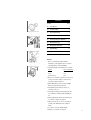
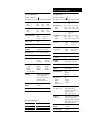
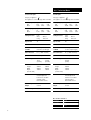
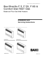
Please leave these instructions with the user
Baxi Brazilia F 5, F 5S, F 8S &
Comfort Stat F8ST Oak
Balanced Flue Gas Wall Heaters
Installation and
Servicing Instructions
Baxi Brazilia F 5
Baxi Brazilia F 5S
Baxi Brazilia F 8S
Baxi Brazilia F 8 Comfort Stat
3003035 / 02
the nation’s favourite for
PLUMBING & HEATING SUPPLIES
FREE SHIPPING
SECURE PAYMENTS
on all orders over £100 to mainland UK
shop online with confidence
FINANCE AVAILABLE
PRICE MATCH
spread the cost with low interest rates
always get the best deals available
we have
H U G E
R E D U C T I O N S
ON THOUSANDS OF ITEMS
Boilers
Bathroom suites
Radiators
Kitchen sinks & taps
Heating controls
Showers
Pipes & ittings
Wet rooms
Cylinders
Towel warmers
Fires
Bathroom furniture
Renewable energy
& much more
visit our website
plumbnation.co.uk
CALL US ON
0844
800
3460
Natural Gas
Propane
Baxi Brazilia F 5
G.C.No. 35 075 01A
Baxi Brazilia F 5 Propane
G.C.No. 35 075 04A
Baxi Brazilia F 5S Grey
G.C.No. 35 075 02A
Baxi Brazilia F 5S Mahogany
G.C.No. 35 075 02A
Baxi Brazilia F 5S Oak
G.C.No. 35 075 02A
Baxi Brazilia F 5S Grey Propane
G.C.No. 35 075 05A
Baxi Brazilia F 8S Grey Propane
G.C.No. 35 075 06A
Baxi Brazilia F 8S Grey
G.C.No. 35 075 03A
Baxi Brazilia F 8S Mahogany
G.C.No. 35 075 03A
Baxi Brazilia F 8S Oak
G.C.No. 35 075 03A
Baxi Brazilia Comfortstat F8ST Oak
G.C.No. 35 075 09
Baxi Heating Ltd is one of the leading manufacturers
of domestic heating products in the UK.
Our first priority is to give a high quality service to our
customers. Quality is built into every Baxi product products which fulfil the demands and needs of
customers, offering choice, efficiency and reliability.
To keep ahead of changing trends, we have made a
commitment to develop new ideas using the
latest technology - with the aim of continuing to
make the products that customers want to buy.
Baxi is also the largest manufacturing partnership in
the country. Everyone who works at the company
has a commitment to quality because, as
shareholders, we know that satisfied customers
mean continued success.
We hope you get a satisfactory service from Baxi. If
not, please let us know.
Baxi is a BS-EN ISO 9001
Accredited Company
2
For GB/IE only.
Contents
Section
Page
1.0
Introduction
4
2.0
Technical Data
5
3.0
Site Requirements
7
4.0
Installation
10
5.0
Commissioning the Appliance
11
6.0
Annual Servicing
12
7.0
Changing Components
13
8.0
Fault Finding
15
9.0
Short Parts List
16
Installer
Before continuing any further with the
installation of this appliance please read the
following guide to manual handling:
•The lifting weight of this appliance is as below:
Model
Gross weight (kg)
F5
18.0.
F 5S
19.1.
F 8S & F 8ST
24.4.
•One person should be sufficient to lift the fire. If
for any reason this weight is considered too
heavy then obtain assistance.
•When lifting always keep your back straight.
Bend your legs and not your back.
•Avoid twisting at the waist. It is better to
reposition your feet.
•Avoid upper body/top heavy bending. Do not
lean forward or sideways whilst handling the
fire.
•Always grip with the palm of the hand. Do not
use the tips of fingers for support.
•Always keep the fire as close to the body as
possible. This will minimise the cantilever
action.
•Use gloves to provide additional grip.
•Always use assistance if required.
3
1.0 Introduction
1.1
Description
1. The Baxi Brazilia F is a range of room sealed
gas convector appliances designed to be used
with gas type G20 (Natural Gas) at supply
pressure 20 mbar.
2. The Baxi Brazilia F range, non thermostatic,
is also available for use with gas type G31
(Propane) at supply pressure 37 mbar. The
procedure for installation, servicing etc. is the
same for both Natural Gas and Propane models.
IMPORTANT: The appliance must only be
used on its designated gas type. This is
indicated on the data label.
Baxi Brazilia F 5
Fig. 1
3. The appliance provides warm air by natural
convection and flueing is by means of a
concentric balanced flue arrangement.
4. Except for Comfort Stat, the appliance is
controlled by a control knob which operates the
ignition and alters the heat output. The control
knob has five positions giving a choice of three
output rates:
Position
Position
OFF
l
Position
Position
Position
Baxi Brazilia F 5S
Fig. 2
LOW
IGNITION
ll
lll
MEDIUM
HIGH
5. (Comfort Stat only)
The appliance is controlled by a control knob
which operates the ignition and alters the
temperature setting, the knob has four positions.
Position
Position
OFF
*
IGNITION PRESET
HIGH
LOW
1.2
Baxi Brazilia F 8S & F 8ST
Fig. 3
Notice
Discolouration of wall surfaces
Most heating appliances generate warm air convection currents and
transfer heat to any wall surface against which they are situated.
Some soft furnishings (such as blown vinyl wallpapers) may not be
suitable for use where they are subject to temperatures above normal
room levels and the manufacturer's advice should be sought before
using this type of wall covering adjacent to any heating appliance.
The likelihood of wall staining from convected air currents will be
increased in environments where high levels of tobacco smoke or other
contaminants exist.
Installation
1. The appliance is suitable for installation only in
G.B. and I.E. and should be installed in
accordance with the rules in force. For Ireland
install in accordance with I.S.813 “Domestic gas
installations”. The installation must be carried out
by a CORGI Registered Installer or other
competent person and be in accordance with the
relevant requirements of GAS SAFETY (Installation
and Use) REGULATIONS latest edition, the BUILDING
REGULATIONS issued by the Department of the
Environment, BUILDING STANDARDS (Scotland)
(Consolidation) REGULATIONS issued by the
Scottish Development Department and the LOCAL
BUILDING REGULATIONS. Where no specific instructions
are given, reference should be made to the relevant
BRITISH STANDARD CODES OF PRACTICE.
2. This appliance must be installed in accordance
with the manufacturers instructions and the rules
in force.
3. Read the instructions before installing or using
this appliance.
NOTE: All illustrations show F 5S, unless
otherwise indicated. The procedure for
installation, commissioning, servicing etc. is the
same for all Brazilia F models.
1.3
4
Important Information
This product contains Refractory Ceramic Fibres (R.C.F.) which are man-made vitreous silicate fibres. Excessive exposure to these materials may cause
irritation to eyes, skin and respiratory tract. It is important to take care when handling these articles to ensure the release of dust or fibres is kept to a
minimum.
To ensure that the release of fibres from these articles is kept to a minimum, during installation and servicing it is recommended that a H.E.P.A. filtered
vacuum is used to remove any dust, soot or other debris accumulated in and around the appliance. This should be performed before and after working on
the installation.
It is recommended that any replaced item(s) are not broken up but sealed within heavy duty polythene bags and clearly labelled “R.C.F. waste”. This is not
classified as “hazardous waste” and may be disposed of at a tipping site licensed for the disposal of industrial waste.
Protective clothing is not required when handling these articles but it is recommended that gloves are worn and the normal hygiene rules of not smoking,
eating or drinking in the work area are followed and always wash hands before eating or drinking.
2.0 Technical Data
F 5 & F 5S Natural Gas
F 8S Natural Gas
Category of Appliance I 2H
The appliance is set for Gas Type G20 at 20mbar.
Category of Appliance I 2H
The appliance is set for Gas Type G20 at 20mbar.
Heat Input (gross)
kW
Btu/h
High
2.05
7,000
Med
1.41
4,800
Low
0.86
3,000
Heat Output (gross) High
kW
1.5
Btu/h
5,100
Med
0.98
3,350
Low
0.57
1,950
Setting Pressure
Cold
mbar
in wg
19.7 ± 0.75
7.9 ± 0.3
Injector Size
CO2
Nox Class
3
Gas Rate
on HIGH
0.195 m3/h (6.89 ft3/h)
Gas Connection
R 1/4 (1 /4 BSP external)
Ignition
Piezo Spark
Packed Weight
5
18 kg
(39.7 lbs)
5S
18.4 kg
(40.6 lbs)
Dimensions
Height
Width
Depth
(from the wall)
5
394mm
426mm
126mm
5S
394mm
450mm
128mm
Controls
Rotary gas tap allowing
manual adjustment
between low, medium
and high output.
Flame failure device.
Thermocouple
Output
8-13mv
Heat Exchanger
Cast Iron
Except Comfort
Comfort Stat
Stat
Heat Input (gross)
kW
Btu/h
Except Comfort
Comfort Stat
Stat
Heat Output (gross) High Med Preset Low
kW
2.26
1.48 1
0.80
Btu/h
7,700 5,050 3,412 2,730
Setting Pressure
F Range
Cold
mbar
in wg
19.25 ± 0.75
7.7 ± 0.3
Setting Pressure
Comfort Stat
Cold
mbar
in wg
17.25 ± 0.75
6.9 ± 0.3
Injector Size
CO1
Nox Class
2
Gas Rate
on HIGH
0.29 m3/h (10.28 ft3 /h)
Gas Connection
R 1/4 (1/4 BSP external)
Ignition
Piezo Spark
Packed Weight
8S
24.4 kg
(54 lbs)
Dimensions
Height
Width
Depth
(from the wall)
8S
430mm
516mm
152mm
Controls
Non Thermostat
Rotary gas tap allowing
manual adjustment
between low, medium
and high output.
Flame failure device.
Controls
Comfort Stat
Rotary thermostat allowing
a preset position and
adjustment between low and
high temperature settings.
Flame failure device.
B.S. Codes of Practice
STANDARD
B.S. 6891
B.S. 5440: Pt. 1
B.S. 5871 Pt.1
SCOPE
Gas Installation.
Flues.
Installation of fires, convector
heaters
High Med Preset Low
3.06
2.21 1.55 1.27
10,440 7,540 5,290 4,333
Thermocouple
Output
8-13mv
Heat Exchanger
Cast Iron
5
2.0 Technical Data
F 5 & F 5S Propane
F 8S Propane
Category of Appliance I 3P
The appliance is set for Gas Type G31 at 37mbar.
Category of Appliance I 3P
The appliance is set for Gas Type G31 at 37mbar.
Heat Input (gross)
kW
Btu/h
High
2.05
7,000
Med
1.41
4,800
Low
0.86
3,000
Heat Input (gross)
kW
Btu/h
Heat Output (gross) High
kW
1.5
Btu/h
5,100
Med
0.98
3,350
Low
0.57
1,950
Heat Output (gross) High
kW
2.26
Btu/h
7,700
Setting Pressure
Cold
mbar
in wg
Setting Pressure
36.5 ± 1
14.6 ± 0.4
High
Med
3.06
2.21
10,440 7,540
Med
1.48
5,050
Cold
mbar
in wg
Low
1.27
4,333
Low
0.80
2,730
36.5 ± 1
14.6 ± 0.4
Injector Size
74
Injector Size
90
Nox Class
3
Nox Class
2
Gas Rate
on HIGH
0.077 m3/h (0.146 kg/h)
Gas Rate
on HIGH
0.115 m3/h (0.218 kg/h)
Gas Connection
R 1/4 (1/4 BSP external)
Gas Connection
R 1/4 (1/4 BSP external)
Ignition
Piezo Spark
Ignition
Piezo Spark
Packed Weight
5
18 kg
(39.7 lbs)
5S
18.4 kg
(40.6 lbs)
Packed Weight
8S
24.4 kg
(54 lbs)
Dimensions
Height
Width
Depth
(from the wall)
5
394mm
426mm
126mm
5S
394mm
450mm
128mm
Dimensions
Height
Width
Depth
(from the wall)
8S
430mm
516mm
152mm
Controls
Rotary gas tap allowing
manual adjustment
between low, medium
and high output.
Flame failure device.
Controls
Rotary gas tap allowing
manual adjustment
between low, medium
and high output.
Flame failure device.
Thermocouple
Output
8-13mv
Thermocouple
Output
8-13mv
Heat Exchanger
Cast Iron
Heat Exchanger
Cast Iron
B.S. Codes of Practice
STANDARD
B.S. 6891
B.S. 5440: Pt. 1
B.S. 5871 Pt.1
6
SCOPE
Gas Installation.
Flues.
Installation of fires, convector
heaters
3.0 Site Requirements
3.1
Location
1. The appliance must be fitted on a suitable
outside wall to meet the requirements of the
balanced flue arrangement.
2. For applications involving walls constructed
from or comprising of combustible material,
reference should be made to the requirements of
B.S. 5871 and Building Regulations.
3. Building Regulations will require the flue duct to
be separated from any combustible material
within the wall by a non-combustible sleeve
enclosing an annular air space of at least 25mm
(1 in) around the flue duct.
4. If the outer face of the wall is combustible, a
plate of metal (or other non-combustible material)
should be fitted over the flue duct extending at
least 50mm (2 in) around the terminal.
5. Further guidance on timber frame construction
is given in the Institute of Gas Engineers UP7.
“Guide for Gas Installations in Timber Framed
Dwellings”.
IMPORTANT: LPG Models.
This appliance must not be installed below
ground in basements, cellars, etc. unless
these are open to ground level on one side.
For further guidance see BS 5871 Pt.1.
3.2
Clearances
1. The appliance must be fitted on a vertical flat
non-combustible wall. Any combustible wall
coverings should be removed from within the area
of the outer case.
2. Internally the appliance must not be fitted under
a shelf or sill which has a projection of more than
150mm (6 in).
3. Curtains or a shelf must not be closer than
140mm (51/2 in) (F 5 & 5S), 89mm (3 1/2 in) (F 8S)
from top of outer case.
4. The bottom of the outer case must be a
minimum of 72mm (27/8 in) from the floor. Subject
to this minimum dimension it is recommended
that the appliance is fitted as close to the floor as
possible for optimum distribution of heat.
5. Minimum side clearance form any wall or fixed
furniture to the outer case is:
Left hand side:
45mm (13/4 in)
Right hand side: 57mm (21/4 in)
7
3.0 Site Requirements
3.3
Flue Position
1. The siting of the balanced flue terminal must
meet the following conditions:
Fig. 4
a. Where the flue terminal of the appliance is
beneath any opening (that is to say, any part of a
window capable of being opened, or any
ventilation inlet or similar opening) no part of the
terminal shall be within 300mm (1 ft), measured
vertically from the bottom of the opening.
b. Where the flue terminal of the appliance is
less than 2m (6 ft) above the level of any ground,
balcony, flat roof or place to which any person
has access and which adjoins the wall in which
the flue terminal is situated, the terminal shall be
protected by a guard.
Fig. 5
Fig. 6
A*
B*
C*
D
E
F
G
H
I
J
K
L
(side view). Angle of drop
shown exaggerated.
Terminal Position with Minimum Distance
(mm)
Directly below an openable window or other opening, e.g. an air brick.
Below gutters.
Below eaves, soil pipes or drain pipes.
Below balconies or car port roof
From vertical drain pipes and soil pipes.
From internal or external corners.
Above ground, roof or balcony level.
From a surface facing a terminal.
From a terminal facing a terminal.
Vertically from a terminal on the same wall.
Horizontally from a terminal on the same wall.
For an opening in a car port (e.g. door, window) into a dwelling.
300
300
300
600
300
600
300
600
600
1500
300
1200
c. The guard must be screwed to the wall over
the flue terminal and be at least 50mm (2 in)
clear of any part of the terminal. A suitable guard
is available direct from Baxi Heating, Part No.
080266 (Fig. 5).
d. Not within 300mm (1 ft) of ground level.
2. Fig. 4 shows the positioning of the flue
terminal relative to buildings and other
structures.
3. If the outer face of the outside wall is of
combustible material (timber, etc.) a metal or
other non-combustible material plate should be
fitted round the flue terminal so that it extends
not less than 50mm (2 in) around the terminal. A
179mm (7 in) square or a 230mm (9 in) diameter
circular plate will meet the requirement.
*In addition, the terminal should not be nearer than 300mm to an opening in the
building fabric formed for the purpose of accommodating a built-in element such
as a window frame or door frame (Fig. 7).
4. The flue should run horizontally, or with a
slight drop to the terminal, in order to prevent
rain entry (Fig. 6).
8
Fig. 7
3.0 Site Requirements
WARNING: 520-610mm Flues are not suitable for Cat I3+
(Butane/Propane) appliances
Flue Option
3.4
Brazilia F Gas Categories
Propane
Cat I3P
F5 & F5S F8S & F8ST F5 & F5S
Part No
Part No
Part No
225174
225174
243842
Wall Thickness F5 & F5S
Part No
225174
Part No
243842
381mm-483mm
(15in - 19in)
o
Part N
225175
o
Part N
243857
o
Part N
225175
Part N
243857
520mm-610mm
(201/2in - 24in)
Part No
243849
Part No
243848
Part No
243849
Part No
243848
125mm-229mm
(5in - 9in)
F8S
1. The standard appliance is supplied with flue
ducting which is adjustable to accommodate wall
thicknesses from 248mm (93/4 in) to 349mm
(133/4 in).
Butane/Propane
Cat I3+
Natural
Cat I2H
o
Part N
225175
o
Flue Dimensions
F8S
Part No
243842
o
Part N
243857
2. Three further flue terminals are available as
optional extras to suit the wall thicknesses
indicated in the table opposite.
Not Available
3.5
Ventilation
1. The appliance is room sealed and therefore
requires no purpose built ventilation.
2. It is intended for use in habitable rooms, and
must not be fitted in cupboards or confined
compartments.
3.6
Gas Supply
1. The inlet connection R1/4 (1/4 BSP external) is
located on the gas tap at the bottom right hand
side of the appliance.
2. A gas service cock must be fitted in the
supply to the appliance with a disconnecting
union between the service cock and the inlet
connection.
NOTE: If the gas supply is run either to the
left or right on leaving the appliance, at least
the first 51mm (2 in) from the inlet connection
must run vertically downwards to avoid the
outer case fouling the gas supply.
9
4.0 Installation
4.1
Preparation
1. Ensure that the length of the flue ducting is
suitable for the wall thickness.
8
2. Select a position for the appliance. Using the
template supplied, mark the position of the flue
ducting and the four fixing holes. Ensure that the
template is vertical (Fig. 8 or 9 depending on
model).
3. Cut a neat hole 127 - 140mm (5 - 51/2 in) in the
wall for the flue.
Fig. 8 (F 8S & F8ST)
4. Drill and plug the wall at the four fixing holes
using a 6mm (1/4 in) drill.
4.2
Fitting the Appliance
1. Slide the flue duct and terminal assembly into
the flue outlet at the rear of the appliance.
Ensure that the flue duct spotwelds are not at the
bottom.
5
2. To determine the flue length, measure the wall
thickness and add 20mm (3/4in). Adjust the
distance from the back of the airbox and the joint
between the terminal and air duct to this
dimension. Using the length of flue tape provided
fix this dimension by taping up the joint between
the flue duct assembly and the flue outlet.
Fig. 9 (F 5 & F 5S)
3. Offer the appliance up to the wall pushing the
terminal and flue ducting through the wall.
4. Ensuring that the appliance is level, secure it
to the wall using four suitable screws and
washers. Check that the wall sealing ring is
correctly positioned and seals against the wall
(Fig. 10).
5. Ensure that the flue terminal protrudes
sufficiently on the outside wall face (Fig. 10).
Make good as appropriate.
6. Connect the gas supply incorporating a gas
service cock and a disconnecting union between
the service cock and the inlet connection.
7. Check for gas soundness (B.S. 6891).
Fig. 10 (Top View)
10
5.0 Commissioning the Appliance
5.1
Commissioning the Appliance
1. Turn on the gas service cock.
2. Fit the control knob onto the control tap
spindle (Fig. 11).
3. Purge any air from the system.
4. Remove the pressure test point screw. Fit a
pressure gauge to the pressure test point
(Fig. 11).
Control Knob
Pressure Test Point
Fig. 11
Igniter removed
for clarity
5. Push the control knob in and turn
anticlockwise to the ignition ( ) position. The
main burner should light. Keep the control knob
pushed in for 20 seconds. If the burner fails to
remain alight repeat the procedure. Check that
the gas supply is correct by measuring the
pressure at the test point on the gas control tap.
6. No adjustment is provided on the appliance. If
it is found that the test pressure is not within the
tolerances given, consult the gas supplier.
7. Push in and turn the control knob back to the
OFF position. Remove pressure gauge and
replace the pressure test point screw.
8. Relight the appliance and check for gas
soundness.
N.G. Setting Pressure (Cold/High Rate)
5 & 5S
8S
19.7 ± 0.75mbar
19.25 ± 0.75mbar
(7.9 ± 0.3in wg)
(7.7 ± 0.3in wg)
5.2
1. Push in and turn the control knob back to the
OFF position.
Comfort Stat
17.25 ± 0.75mbar
(6.9 ± 0.3in wg)
2. Remove the knob from the appliance by gently
pulling the knob forward (Fig. 11).
3. Fit the outer case by locating the slots in the
outer case rear strip onto the four mounting lugs
on the wall brackets (Fig. 13).
L.P.G. Setting Pressure (Cold/High Rate)
5 & 5S
36.5 ± 1mbar
(14.6 ± 0.4in wg)
8S
36.5 ± 1mbar
(14.6 ± 0.4in wg)
Fitting the Outer Case
Fig. 12
4. Replace the control knob (Fig. 13).
5.3
Instructing the User
1. Explain how to ignite the appliance and alter
the heat settings.
2. Show the position of the external gas service
cock.
3. Instruct the user that the bottom and top of the
case must never be obstructed in any way and
emphasise that clothes etc must never be hung
over the appliance to dry as this will cause
overheating and possible damage.
Mounting Lugs
Fig. 13
4. Hand over the User’s and Installation and
Servicing Instructions and recommend that for
reasons of safety and economy the appliance
should be serviced annually by a competent
person.
Viewing Window
11
6.0 Annual Servicing
6.1
Servicing the Appliance
1. For reasons of safety and economy the
appliance should be serviced annually
2. Before servicing please read Section 1.3
Important Information.
Outer Case
3. Turn off the gas supply and ensure that the
appliance is cold.
Fig. 14
4. Remove the control knob by pulling forward,
then remove the case by easing upwards and
forwards until it is clear of its retaining lugs
(Fig. 14).
Control Knob
5. Undo the heat exchanger retaining nuts and
washers (Fig. 15) and draw the casting forwards
off the locating studs.
6. Remove the three screws holding the burner
retaining plate to the airbox and undo the
thermocouple nut from the gas tap (Fig. 16 & 19).
Fig. 15
Rope Seal
8. Disengage the burner from the injector and pull
the electrode lead off the spark electrode
(Fig. 16).
Heat Exchanger Casting
Burner Retaining Plate
9. Check that the insulation is undamaged.
Replace if necessary. (8S only - Check that the
aluminium foil is undamaged. Replace if
necessary) (Fig. 18).
Fig. 16
Burner Gauze
10. Remove and clean the injector and sealing
washer. The injector must not be cleaned with a
needle or wire (Fig. 19). If the sealing washer is
damaged it must be replaced.
Spark
Electrode
Flue Outlet Tube
Burner Flame Ports
Insulation
11. Check that the flue outlet tube is clear
(Fig. 18).
12. Brush away any dirt from the heat exchanger
casting. If necessary clean the viewing window.
13. With a light brush carefully remove deposits
from the spark electrode, burner flame ports and
the burner gauze (Fig. 16).
Fig. 17
14. Replace the rope seal in the heat exchanger
casting if it is damaged in any way (Fig. 15). Also
examine the thermocouple and replace if
necessary.
Grommet
Electrode Lead
Fig. 18
Thermocouple
15. Re-assemble the injector, washer and burner
assembly in reverse order of dismantling. Ensure
that the spark gap is correct ie. 3.5mm ± 0.5mm.
Check that the burner is horizontal and correctly
positioned on the injector with the gauze covering
the primary aeration hole.
16. Check the gas pressure at the test point on
the gas control tap. If the pressure is not within
the tolerance, (see Section 2.0 Technical Data)
the gas supply to the unit needs to be
investigated.
Gas Tap
Thermocouple
Injector
7. Ease the thermocouple and electrode lead
from the rubber grommet (Fig. 17).
Fig. 19
17. Check that the burner ignition is satisfactory.
Ensure that the thermocouple/electrode lead
grommet is correctly positioned and re-fit the heat
exchanger casting.
18. Check for gas soundness.
Washer
12
Electrode Lead
19. Fit the case and control knob and re-check
that the ignition is satisfactory.
7.0 Changing Components
Fig. 20
7.1
Changing Components
1. Before changing any components please read
Section 1.3 Important Information.
2. Turn off the gas supply and ensure that the
appliance is cold.
Mounting Lugs
3.Remove the control knob by pulling forward,
then remove the case by easing upwards and
forwards until it is clear of its retaining lugs
(Fig. 20).
4. After changing any components
re-commission the appliance
7.2
Fig. 21
Piezo Unit (Fig. 21).
1. Pull off the spark lead at the rear of the igniter.
Tabs
Electrode
Lead
Igniter
Burner Retaining Plate
2. Straighten the tabs securing the piezo unit to
the tap retaining plate and remove.
3. Fit the new piezo unit and twist the tabs
slightly to secure.
Fig. 22
4. Replace all components in the reverse order of
dismantling.
Burner Gauze
7.3
Spark
Electrode
Flue Outlet Tube
Burner Flame Ports
Gas Control Tap or Thermostat
1. Undo the heat exchanger retaining nuts and
washers and draw the casting forwards off the
locating studs.
Insulation
2. Remove the three screws holding the burner
retaining plate to the airbox and undo the
thermocouple nut from the gas tap (Fig. 22 & 24).
Fig. 23
3. Ease the thermocouple and electrode leads
from the rubber grommet (Fig. 23).
4. Disengage the burner from the injector and
pull the electrode lead off the spark electrode
(Fig. 22).
Grommet
Electrode Lead
5. Pull off the spark electrode lead at the rear of
the igniter (Fig. 24).
Thermocouple
6. Remove the supply pipe from the gas tap.
Gas Tap Locating
Bracket
7. Undo the nut holding the gas tap to its
retaining bracket, and disengage the tap from the
bracket (Fig. 24).
Thermocouple
Fig. 24
Gas Tap
7a.Undo the screw holding the thermostat
locating bracket to the fire body, and disingage
the thermostat from the fire.
8. Remove the injector and sealing washer. If the
washer is damaged it must be replaced.
Injector
Washer
Electrode Lead
9. On re-assembly ensure that the airbox sealing
grommet is correctly positioned and check for
gas soundness.
13
7.0 Changing Components
Fig. 25
7.4
Burner
1. Undo the heat exchanger retaining nuts and
washers and draw the casting forwards off the
locating studs (Fig. 25).
2. Remove the three screws holding the burner
retaining plate to the airbox, also remove the
insulation and undo the thermocouple nut from
the gas tap (Fig. 26 & 28).
Rope Seal
Heat Exchanger Casting
Burner Retaining Plate
Fig. 26
Thermocouple
3. Ease the thermocouple and electrode lead
from the rubber grommet (Fig. 27).
4. Disengage the burner from the injector and
pull the electrode lead off the spark electrode
(Fig. 26).
5. Remove the intake gauze from the burner inlet
and undo the screws securing the burner to its’
retaining plate, noting the position of the shield at
the left hand side (Fig. 26).
6. Undo the screw securing the spark electrode
to the burner. Fit the electrode to the new burner
(Fig. 26).
Spark Electrode
Electrode Lead
Burner Gauze
7. Fit the intake gauze to the burner inlet
ensuring that it covers the primary aeration hole
(Fig. 26).
8. Reassemble in reverse order of dismantling.
7.5
Injector
Shield
1. Remove the burner as described in sections
7.4.1 to 7.4.4 .
2. Undo the injector and sealing washer,
retaining the washer for use with the new
injector. If the washer is damaged it must be
replaced.(Fig. 28).
Fig. 27
3. Reassemble in reverse order of dismantling.
7.6
Grommet
Thermocouple
1. Remove the burner as described in sections
7.4.1 to 7.4.4 .
Electrode Lead
Thermocouple
2. Undo the nut retaining the thermocouple tip to
the burner bracket and withdraw the
thermocouple (Fig. 26).
3. Bend the new thermocouple in a similar
manner to the one removed. Avoid any sharp
bends.
Gas Tap
Thermocouple
4. On reassembly ensure that the airbox sealing
grommet is correctly positioned.
Injector
Washer
14
Fig. 28
Electrode Lead
Ensure all installation criteria
have been satisfied before
performing Fault Finding
(e.g. flue terminal position).
8.0 Fault Finding
7±1.5mm
Fig. 29
3.5±0.5mm
15
9.0 Short parts list
Key G.C.
No. No.
D
G / Q, R
Description
Manufacturers
Part No.
A
205890 Knob Control (5)
234632
B
205887 Knob Control (5S)
234637
C
205894 Knob Control (8S)
234643
D
205837 Burner (5/5S)
224041
E
205864 Burner (8S)
223963
F
205873 Electrode Spark
223940
G
E01357 Igniter/Gas Tap (5/5S)
E01358 Igniter/Gas Tap (8S)
243875
243873
H
393734 Piezo Igniter/Generator 042941
I
381941 Injector (5/5S)
224047
J
381942 Injector (8S)
224104
K
205844 Insulation (5/5S)
224048
L
E01359 Insulation (8S)
243896
M
155654 Lead Electrode
043043
N
E01360 Thermocouple
243870
O
384248 Tap Mag Unit
082462
P
********
3002968
E
H
N
K
M
L
Thermostat Assy
F
A/B
For LPG models only
C
Q
E01361 Igniter / Gas Tap
LPG (5/5S)
243867
R
E01362 Igniter / Gas Tap
LPG (8S)
243872
S
E01363 Injector (5/5S)
LPG
243867
T
E01364 Injector (8S)
LPG
243867
O
P
I/J/S/T
16
10.0 Notes
17
10.0 Notes
18
Baxi Heating Ltd manufacture a comprehensive range
of products for the domestic heating market.
Gas Central Heating Boilers
(Wall, Floor and Fireside models).
Independent Gas Fires.
Renewal Firefronts.
Gas Wall Heaters.
Solid Fuel Fires.
If you require information on any of these products,
please write, telephone or fax to the Sales
Department.
19
The Baxi Helplines
For General Enquiries
+44 (0) 8706 061 064
For After Sales Service
+44 (0) 8706 090 081
For Technical Enquiries
+44 (0) 8706 061 065
Baxi Fires Division
Wood Lane
Erdington
Birmingham
B24 9QP
www.firesandstoves.co.uk