1
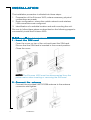
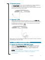
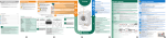
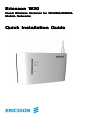
Ericsson W20
Fixed Wir
eless T
erminal for WCDMA/HSDP
A
Wireless
Terminal
WCDMA/HSDPA
Mobile Networks
Quick Installation Guide
No part of this document may
be reproduced in any form
without
permission
from
the
copyright owner
owner..
The contents of this document
are subject to revision without
notice
due
to
continued
ess
in
methodology
pr
ogr
methodology,,
progr
ogress
design,
and
manufacturing.
Ericsson shall have no liability
for any error or damage of any
kind resulting from the use of
this document.
© Ericsson Enterprise AB 2006
All rights reserved.
LZT 108 8745 R1
Table of Contents
INTRODUCTION ............................. 3
Package Contents ................................. 3
Requirements ........................................ 3
INSTALLATION ................................ 4
Unit Preparation .................................... 4
Basic Configuration ............................... 5
Choosing a Location .............................. 7
HARDWARE DESCRIPTION ............ 8
Connectors ........................................... 8
Indicators .............................................. 9
INTRODUCTION
This Quick Installation Guide provides instructions on how to install
and get started with your Ericsson W20 Fixed Wireless Terminal.
For further information about the product, advanced configuration,
and troubleshooting, see the User’s Guide included on the enclosed
CD.
For information about connection of services, please contact your
service provider.
NOTE! Carefully read the document containing safety and regulatory
information included on the enclosed CD.
P
ACKAGE CONTENTS
PACKAGE
The Ericsson W20 package includes the items listed below:
•
•
•
•
•
•
•
Ericsson W20 unit
UMTS/GSM antenna
Power supply adapter
Power cord
Ethernet cable
Quick Installation Guide
CD
Verify that all items are included in the package before proceeding
with the installation. If any item is missing or damaged, please contact the dealer/service provider from which the equipment was
purchased.
REQUIREMENTS
To install your Ericsson W20 you need the following items:
•
A SIM card and configuration details (such as PIN code, APN,
etc.) provided by your service provider. The SIM card contains
information about your subscription and the services included.
•
A PC with an Ethernet network interface for basic configuration
of the unit.
Introduction
3
INST
ALLA
TION
INSTALLA
ALLATION
The installation procedure is divided into three steps:
1. Preparation of the Ericsson W20, where necessary physical
connections are made.
2. Basic configuration, where the mobile network and wireless
LAN connections are configured.
3. Identification of a suitable location and wall mounting the unit.
Be sure to follow these steps as described on the following pages to
successfully install the Ericsson W20.
1 - UNIT PREP
ARA
TION
PREPARA
ARATION
1 . Insert the SIM card
Open the cover on top of the unit and insert the SIM card.
Ensure that the SIM card is inserted in the correct position.
Close the cover.
NOTE! The Ericsson W20 must be disconnected from the
power mains when inserting or removing the SIM card.
2 . Connect the antenna
Connect the provided UMTS/GSM antenna to the antenna
connector and tighten.
4
Installation
3. Connect power
Connect the cable from the enclosed power supply adapter to
the 10-28 VDC power input on the Ericsson W20.
Connect the power cord to the power supply adapter and then
insert the plug into a mains outlet.
4 . Connect a PC
1-4
Attach the enclosed Ethernet cable to one of the LAN (1-4
1-4)
connectors on the Ericsson W20 and connect the other end to
the Ethernet connector on a PC. This connector is most likely
marked with this symbol:
After power up, allow approximately one minute for start-up before
proceeding to the next step.
2 - BASIC CONFIGURA
TION
CONFIGURATION
1 . Access the Ericsson W20 Web pages
Start a web browser on the PC connected to your Ericsson
W20, type http://192.168.1.1 in the address field, and
press the Enter key. The “User login” page is displayed as
shown on the next page.
NOTE! If this page does not appear, verify that the TCP/IP
settings in the PC are set to “Obtain an IP address
automatically”.
Installation
5
The “User login” page is displayed:
Type user in both the “User name” and “Password” text fields
and click the Login button. The “Overview” page is displayed:
2 . Run the Configuration Wizard
The Configuration Wizard can be used for easy setup of the
mobile network and wireless LAN connections.
To start the wizard, click Configuration Wizar
Wizard
d and then
follow the onscreen instructions to complete the wizard.
Only enter the Internet authentication details (PIN, APN, and/or
PPP details) you have received from your service provider, and
leave other text fields empty.
There are important security issues involved when using a
wireless LAN. Please read the information in the User’s Guide.
3 . Mobile network search
Once you have finished the Configuration Wizard, the Ericsson
W20 automatically starts searching for a network. This is
indicated by the flashing Mobile Network indicator.
When a network is found, the Mobile Network indicator
shows a steady green or yellow light depending on the type of
mobile network (UMTS or GSM) with which your Ericsson W20
has established a connection.
6
Installation
3 - CHOOSING A LOCA
TION
LOCATION
The Ericsson W20 has primarily been designed to be wall mounted.
Always select an indoor location, preferably close to a window and
the ceiling which generally will give the best conditions for both the
mobile network and wireless LAN.
For best results, place the Ericsson W20 away from microwave
ovens and other transmitters (e.g. security/alarm systems) as they
can cause signal interference.
UMTS/GSM signal quality
The Ericsson W20 connects to the UMTS mobile network, and if it is
not available the GSM network is used as fall-back. The UMTS/GSM
signal quality available at the Ericsson W20 location affects the
performance of the unit.
The signal quality can be verified on the Ericsson W20 Internet
web page.
If you experience poor reception quality, an external antenna (indoor
window or outdoor roof mounted) may improve reception. Such
antennas are available as accessories for the Ericsson W20.
Wall mounting
The Ericsson W20 is mounted to the wall using two screws and the
two mounting slots on the unit.
Insert and secure two screws in the wall at a distance of 110 mm.
Leave a space of approximately 3 mm between the surface and the
bottom of the screw heads. Slip the Ericsson W20 slots over the
screw heads and pull down until the unit is seated securely.
Installation
7
HARDWARE DESCRIPTION
CONNECTORS
The connectors on the Ericsson W20 are positioned as shown in the
illustration below. A description of each connector is provided in the
table below (from left to right):
Label
Description
10-28
VDC
Power input for connecting the included power
supply adapter.
Reset
Reset button used to restore the Ericsson W20
to its factory default settings.
The following procedure will reset ALL
configurable values back to their factory default,
including the login User name and Password:
1 . Disconnect the power cable from the
Ericsson W20.
2 . Press and hold the Reset button with the tip
of a pen and then reconnect the power
cable. Keep the button pressed for at least
20 seconds.
3 . The Ericsson W20 will restart and come
online with the factory default settings.
8
USB
USB connectors, for connecting the Ericsson W20
to USB devices (for printer and file sharing).
LAN 1-4
Ethernet LAN connectors (RJ45), for connecting
the Ericsson W20 to client PCs or an Ethernet
switch/hub.
Hardware Description
INDICA
TORS
INDICATORS
The front panel of the Ericsson W20 has five (5) status indicators. A
general description of each indicator is provided in the table below
(from top to bottom):
Te x t
S t a t u s Description
Power
Green
Unlit
Power is on.
Power is off.
Mobile
Network
Green
Yellow
Flashing
Unlit
UMTS network is available.
GSM network is available.
Searching for a connection.
No connection to the mobile network.
Internet
Green
Unlit
Connection to Internet established.
No Internet connection.
Wireless Green
LAN
Unlit
The Wireless LAN is active.
The Wireless LAN is inactive.
Alarm
Various error conditions specified on the
Ericsson W20 Overview web page.
No error.
Red
Unlit
The four Ethernet LAN connectors (LAN1-LAN4) have two built-in
green indicators each, one indicating link and the other indicating
activity.
Hardware Description
9
© Ericsson Enterprise AB 2006
LZT 108 8745 R1