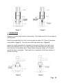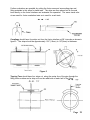
1
Electrofusion Installation
Procedure Manual
It is important to read and understand all instructions before
attempting a fusion. Permanent field installations should be done
only by operators who have been properly trained and certified as
qualified. Should you have any questions or need installation
training, please contact
Central Plastics Company at 1-800-654-3872
or
Your Local Central Plastics Representative.
The following procedures were written to assist trained field personnel in the use
of the Central Plastics Electrofusion system and Central Electrofusion Fittings.
While technical data and advice contained herein is based upon tests and information believed to be reliable, user should not rely upon it absolutely for specific
applications. All data is given and accepted at user’s risk and confirmation of its
validity and stability in particular cases should be obtained independently. Central Plastics makes no guarantee of results and assumes no obligation or liability
in connection with its advice. The integrity of the piping system is the ultimate
responsibility of the installer. This publication is not to be taken as a license to
operate under, or recommendation to infringe any
patents.
REV 5/03rp
Table of Contents
Before You Start
1
Electrofusion Power Requirements
2
Proper Pipe Preparation for Electrofusion
3
Acceptable Markers for Electrofusion
4
Pipe Re-Rounding Statement
5
Fitting Restraint Statement
7
Barcode Scanning Instructions
8
Electrofusion Cooling Statement
9
Re-Fusion of Electrofusion Fittings Recommendation
10
Hydrostatic Testing of Electrofusion Fittings
11
Electrofusion Joining Procedures
for Couplings
12
Electrofusion Joining Procedures
for Sidewall/Saddle Fittings with Under-Clamp
15
Electrofusion Joining Procedures
for Sidewall/Saddle Fittings with Top-Load Clamp
17
Electrofusion Joining Procedures
for Branch Saddle Fittings with T-Clamp
18
Electrofusion Joining Procedures
for Flex Restraints with Ratchet Strap Clamp
22
Examples of Incorrect Electrofusion Joints
24
Destructive Testing Procedures for Electrofusion
Fitting Qualification
27
Before You Start
The following is an installation guide for the purpose of assisting the installer in adequately
preparing an electrofusion fitting and pipe for fusion. This document is a guide only, and
should not be used in place of training by an authorized electrofusion instructor. The
recommended joining procedures for the Central Electrofusion System detailed in this
manual have been qualified in accordance with D.O.T. 192.283
Central Plastics Company strongly recommends that electrofusion fittings be installed only
by persons that have received training from an authorized instructor, that have a strong
working knowledge of polyethylene and heat fusion, and have qualified electrofusion joints
through destructive testing. Persons responsible for the joining of polyethylene pipe by
fusion methods must qualify according to the requirement of the Title 49 Code of Federal
Regulations, Section 192.285.
The installer of the electrofusion fittings for pressure applications should have knowledge of
the intended application and is responsible for any fitting that is installed into a system that
is not suitable for electrofusion fittings. Central Plastics electrofusion fittings are designed
for use on pipe conforming to ASTM standard D2513 & F714 dimensions and with fittings
conforming to D3261. All pipe to which these fittings are installed should meet the dimensional requirements of these standards.
Whether the installer is in a controlled environment or in the field making electrofusion
fitting joints, Central Plastics recommends that you have the following equipment:
1. PIPE PREPARATION EQUIPMENT
Pipe Cutting Tools
Pipe Scraping Tools
Pipe Cleaning Material
Pipe re-rounding tools (on larger pipe sizes)
2. PIPE RESTRAINT EQUIPMENT
3. FUSION EQUIPMENT
Fusion Processor with correct leads and/or tips
Adequate power supply
IMPORTANT NOTE:
Pipe preparation and contamination are very important considerations in the
electrofusion process. Careful attention must be given to proper scraping
and cleaning procedures.
Page 1
ELECTROFUSION POWER REQUIREMENTS
GENERATORS
For the installation of electrofusion fittings in field applications, it will be necessary to have a reliable source of
AC power for the Electrofusion Processor to work properly in supplying the fitting with the right amount of
energy. Generators used as an AC power source should conform to the following;
·
·
·
·
Be well maintained and subjected to a periodic maintenance schedule;
Provide an output voltage in the range that meets the specifications of the applicable
processor model;
Operate within a frequency range of 45 Hertz minimum to 75 Hertz maximum;
A minimum wattage capacity of;
Minimum
KVA
5.0 KVA
3.5 KVA
2.0 KVA
Fitting Range
Will fuse all Central Plastics fittings including 24" DIPS / 630 mm couplings
Will fuse Couplings up to 8"/ 225 mm and all Tapping Tees, High Volume Tapping Tees,
Branch Saddles and Reducers
Will fuse Couplings up to 1 1/4", and all Tapping Tees, High Volume Tapping Tees,
Branch Saddles and Reducers
·
A matching outlet is needed to mate with the plug equipped with the unit by Central:
120V models — 30 Amp, 125 Volt, NEMA L5, twist-lock;
INVERTERS
Inverters can be used as an acceptable AC power source but with the continuing changes in inverter technologies,
earlier processor models may not be compatible to the quasi-sine waveform produced by some inverters. Central
recommends performing compatibility tests using the lightest and heaviest anticipated loads before approving an inverter
system. Feel free to contact Central to discuss issues regarding the use of inverters.
EXTENSION CORDS
Due to the amperage draw of electrofusion fittings, use of extension cords are not encouraged but in the event it becomes necessary to use one the following lengths and wire gages are recommended:
Cord Length
25 ft.
50 ft.
Wire Gage
#10/3 wire (6 mm2)
# 8/3 wire (10 mm2)
NO EXTENTION CORDS SHOULD BE USED ON 14” IPS & LARGER COUPLINGS
PIGTAILS - (30 Amp Twist Lock to 15 Amp Standard Plug Adapter)
The use of pigtails for in field applications of electrofusion fittings is not recommended except on fitting sizes 2" and
smaller.
POWERING UP
Prior to beginning the electrofusion sequence, it is important that you ensure the following:
·
·
The generator has enough fuel to complete the electrofusion cycle
The throttle is opened all the way (in anticipation of power draw)
IMPORTANT NOTE FOR COLD WEATHER INSTALLATIONS:
Cold weather affects both fittings and equipment. Electrofusion fittings require more energy at the beginning of the fusion
cycle, this requirement is increased in cold weather situations. Make sure that your generator is in good mechanical
condition and that it meets the minimum wattage output.
Page 2
Proper Pipe Preparation for Electrofusion Fittings
For a pipe surface to be properly prepared for electrofusion the outer layer or “skin” of
the pipe should be removed to expose a clean, virgin pipe material. This can be
achieved by using one of several types of approved scraping tools. “Approved”
scraping tools can vary widely between electrofusion manufacturers and they may not
necessarily be a tool that is manufactured by the fitting manufacturer. A few examples
of scraping tools that Central Plastics classifies as “approved” are; a rasp type tool
(Stanley Surform Model 21-296 or equivalent), a metal blade paint scraper, or tools
manufactured specifically for electrofusion scraping. “Approved” simply indicates that
the tool has been qualified by the manufacturer and has been found to perform in a
satisfactory manner under the joining conditions established by the manufacturer.
Wood rasps or metal files are not considered acceptable.
It is very important to note that abrasive materials, such as sandpaper or emory cloth,
should never be used in place of a scraping tool. Abrasive materials have been proven
to be ineffective in the removal of sufficient amounts of surface material needed to
achieve an electrofusion bond and in fact, they have actually been shown to impede
the electrofusion process. This is due to the grit or grit like residue they imbed into the
pipe area being scraped, which in turn acts as a barrier between the pipe and fitting.
The electrofusion process significantly differs from conventional heat fusion. In the
electrofusion process there is very little material movement or melt displacement (i.e.
melt beads).
For this reason, any contaminant that is present on the surface of the
pipe will remain sandwiched between the pipe and fitting interface and will ultimately
prevent the two materials from joining. It is also recommended that the “Metal File”
type of rasp not be used as a pipe scraper; as the pipe material is removed with this
type of tool, tends to ball up and roll around on the pipe surface instead of being
cleanly removed and directed away.
Central Plastics Company recommends that a minimum of .007” to .010” of the pipe’s
surface material be removed during the scraping process in order to expose a clean
virgin material. This is approximately the thickness of two sheets of paper. It is important that the pipe surface be clean and free from any type of contaminants that may be
spread before scraping begins. Should the pipe surface be contaminated with dirt,
mud or drilling fluids before scraping, plain water may be used to remove the surface
level of these contaminates. It should be noted however, that water cannot be used to
clean the pipe surfaces once the virgin material has been exposed. In those instances a minimum 70% isopropyl alcohol concentration, with no additional additives, has been found to be highly effective in removing these type of contaminates
and is recommended by Central Plastics as a cleaning agent that can be used before
and after scraping. For applications where a fitting will be moved around on the pipe,
such as a repair application where a coupling will be pushed completely over one end
of the pipe, it is recommended that pipe be scraped for the entire length of the coupling to prevent a clean fitting from being contaminated by unscraped pipe.
Page 3
Markers
Marks can be made on the outer surface of the pipe as a visual aid to help indicate
the required scraper coverage. Marks made on the pipe should not be made with a
“grease pencil” or other type of petroleum based marker that will leave a contaminate
behind. Central Plastics Company’s only requirement for markers used on PE
pipe during electrofusion preparation is that the marker be non-petroleum
based. Grease pencils are generally petroleum based and therefore should not be
used on PE pipe prior to electrofusion joining.
We have found many different types and brands of markers to be acceptable and
recommend that any permanent marker of a color that will show on the pipe material
can be used. The permanent type markers, such as the, “Sharpie”, “Marks-A-Lot”
and “Magic Marker” by Avery are adequate for marking yellow or light colored pipe.
Fast drying paint pens, such as those manufactured by PENTEL and Faber Castell,
also work well and are available in colors that will show well on black pipe; it is
sometimes necessary to allow for drying when using paint type pens. We have also
found that a wax based “China Marker”, although not permanent, works well for marking black pipe. We have found no advantage of one type of marker, permanent or
paint, over the other.
Page 4
Re-Rounding
The non-brittle and flexible material characteristic of polyethylene makes it ideal for
many pressure and non-pressure applications. But this material characteristic alone
brings with it an important consideration that must be taken into account when using
polyethylene pipe.
“Care must be taken to ensure that the polyethylene pipe is not out-of-round
before attempting the electrofusion process.”
HOW DOES POLYETHYLENE PIPE BECOME OUT- OF- ROUND?
1. FROM THE MANUFACTURER: It is important for the installer to confirm that the
polyethylene pipe meets all dimensional requirements of ASTM 2513 and F714 and
that the pipe does not exceed 5% ovality. If ovality is greater than 5% (see chart
below), the installer must take steps to re-round the pipe.
PIPE SIZE
4
5
IPS SIZES
NOMINAL
MINIMUM
DIAMETER
DIAMETER
4.500
4.480
5.563
5.538
MAXIMUM
DIAMETER
4.520
5.588
6
7
8
6.625
7.125
8.625
6.595
7.091
8.586
6.655
7.159
8.664
10
12
14
16
10.750
12.750
14.000
16.000
10.702
12.693
13.937
15.928
10.798
12.807
14.063
16.072
18
20
22
18.000
20.000
22.000
17.919
19.910
21.901
18.081
20.090
22.099
24
26
28
24.000
26.000
28.000
23.892
25.883
27.874
24.108
26.117
28.126
30
32
34
30.000
32.000
34.000
29.865
31.865
33.347
30.135
32.144
34.153
36
42
48
36.000
42.000
48.000
35.838
41.811
47.784
36.162
42.189
48.216
PIPE SIZE
4
6
8
10
12
14
16
18
20
24
30
36
42
48
DIPS SIZES
NOMINAL
MINIMUM
DIAMETER
DIAMETER
4.800
4.778
6.900
6.869
9.050
9.009
11.100
11.050
13.200
13.141
15.300
15.231
17.400
17.322
19.500
19.412
21.600
21.503
25.800
25.684
32.000
31.886
38.300
38.128
44.500
44.300
50.800
50.571
MAXIMUM
DIAMETER
4.822
6.931
9.091
11.150
13.259
15.369
17.478
19.588
21.697
25.916
32.114
38.472
44.700
51.029
2. IN THE WAREHOUSE: Polyethylene pipe that is warehoused for a period of time or
stacked on top of each other can experience ovality related issues (this is more
pronounced with large diameter pipe).
3. OVER TIME: Large Diameter Polyethylene pipe will tend to relax a little during
storage due to a combination of its weight and its natural flexibility.
4. DURING INSTALLATION: Mechanical forces experienced during some trenchless
installation techniques such as Pipe Bursting or Directional Drilling can temporarily
leave the Polyethylene pipe elongated and out-of-round.
5. PREVIOUSLY INSTALLED: Polyethylene pipe that has been underground for
awhile is subjected to earth loads. These earth loads can cause the pipe to sag and/
or become out-of-round.
Page 5
WHY IS IT IMPORTANT TO ADDRESS THE OUT-OF-ROUND ISSUE FOR ELECTROFUSION INSTALLATIONS?
One of the most critical functions of the electrofusion process is to close the gap between the
pipe and the fitting and to build up interfacial pressures for the fusion process to take place. If
this gap is not closed and the interfacial pressures cannot be built up, there is no way for the
electrofusion joint to effectively achieve the high level of fusion integrity for which it was designed. If a pipe is out-of-round the initial concern is that the surface area of the pipe may not
adequately come in contact with the fusion zone of the electrofusion fitting. This could result in
the electrofusion fittings cold zones, that are designed to contain the material generated in
the melt pool, to simply allow the molten material to escape out of the fusion area without
producing any melt penetration. This is a particularly important concern when installing tapping
tees and branch saddles since they do not fully encircle the pipe as will an electrofusion coupling.
HOW DO YOU CORRECT AN OUT-OF ROUND CONDITION?
First, determine if out-of-round conditions exists. This can be done visually for the more extreme cases or it can be done by measuring the pipe diameter with tape measure to determine the High/Low points of the pipe (see Figure A). If the High/Low measurements exceed
the maximum pipe O.D. tolerance, a re-rounding clamp or device must be used to bring the
pipe back to a round condition. (see Table1 for equipment examples)
Product Specific Clamping Devices (e.g. saddle clamps, t-clamps, etc)
Clamp Kits (multi-clamp kit for 4" and under)
Pipe Clamps from butt-fusion machines
Full-encirclement clamps (i.e. Victaulic Clamps)
Porta-Power Tools
Table 1
Page 6
FITTING RESTRAINT
ELECTROFUSION COUPLINGS
Important Note:
All Electrofusion Couplings (regardless of manufacturer) require the pipe
to be restrained or sufficiently supported on each side of the pipe to; a)
restrict movement during the fusion and cooling process, and b) alleviate or eliminate sources of stress and/or strain until both the fusion cycle
and the cooling cycle are completed.
Central Plastics recommends the use of some form of pipe restraint and/or
support for the primary purpose of controlling and eliminating any movement
of the fitting due to fusion pressures generated during the fusion process
and/or any external forces exerted on the pipe or the fitting. The basis for
using pipe restraint and/or support when joining two pieces of PE pipe with an
electrofusion coupling is to:
·
·
·
Minimize potential short-stab, mis-stab or binding situations
Ensure proper cold-zone contact with the prepared fusion area so that
sufficient interfacial pressure is built up.
Eliminate unwanted loss of molten material from the fusion zone
(resulting loss of interfacial pressure can be a source of voiding or a
defective and unsatisfactory joint)
A properly prepared and assembled joint that is kept stationary and free
from stresses and strains during the fusion process and recommended
cooling time should have good joint integrity.
ELECTROFUSION SADDLES
Electrofusion Saddle fittings (Tapping Tees, Branch Saddles, Corp Saddles,
etc.) Installation of an electrofusion saddle requires the use of recommended restraint systems for the purpose of;
·
·
·
Holding the fitting in place during the fusion process
Eliminating fitting movement due to material expansion
Ensuring proper cold-zone contact with the prepared fusion area so
that sufficient interfacial pressure is built up.
Page 7
Note: Barcode Scanning Instructions
Be sure the processor is ready and the display is reading “Read Data”. It is critical
that the tip of the barcode reader be touching the barcode label. While holding the
reader at a 15 to 30 degree angle start the scan beginning in the white area on one
side of the label and move the reader evenly across the barcode into the white area
on the opposite side. Move the reader in a smooth quick motion, without stopping,
all the way across the label. The label can be read in either direction, front to back
or back to front. The processor should make an audible signal when the barcode
has been accepted.
Most difficulties experienced in barcode scanning are simple problems involving
technique. Ensure that the display reads “Read Data” before attempting to scan a
barcode label. Make sure the tip light is illuminated on the reader. If not, check
cable connections. Be sure the reader tip is clean and free from dirt and debris.
Move the reader pen across the barcode from white area to white area without
stopping.
Page 8
Electrofusion Fitting Cooling
One of the most misunderstood and often ignored components of the entire electrofusion
process is the cooling phase. It is often assumed that if the fitting is cool enough to
touch it must be cool enough to remove the restraint device or even pressure test the
connections. The cooling phase is critical to the success of the electrofusion process and careful attention should be given to insure that the stated cooling times are
properly adhered to.
The importance of the cooling phase can be illustrated in the actions of the melt pool.
Using the following Figure we will look closer at the melt pool stages created during
the electrofusion process.
Electrofusion Fitting Fusion Cycle
Interface Temperature vs Time Curve
Point of Current Termination & Optimum
Bonding Temperature
2
The complete FUSION CYCLE consists of:
B)
Temperature [C]
C)
A) The Melt Generation Phase
B) The Melt Containment Phase
C) The Melt Co-Crystallization Phase
D) The Melt Cooling Phase
A)
D)
(see Concept of Electrofusion Theory statement for more details)
Polymer Melts
&
Polymer Solidifies
1
Beginning of Fusion
Cycle
End of Specified Fusion
Time or end of heat cycle
3
Acceptable Temperature/Time to remove
restraint devices
Acceptable Temperature/Time to perform
pressure testing
Time [s]
1
UnFused Joint
2
Liquefied Melt Pool
3
Solidified Melt Pool
MELT POOL STAGES
When current is applied to the fitting, the plastic in the fitting and on the pipe surface
begins to melt and form a melt pool (A & B). With continued application of current, the
melt pool deepens at the pipe and fitting interface which in turn forces internal pressures to build up. This process is known as co-crystallization between the melted
pipe and fitting material (C). The cooling phase (D) (combined with the design of the
fitting) provides a controlled environment between the pipe and the fitting where resolidification can effectively take place. This cooling phase begins immediately following the termination of current being supplied to the fitting and continues for a
period of time beyond the point where the PE polymer resolidifies (also known as
clamping time). This allows ample time for the fusion area to regain the strength and
flexibility it exhibited prior to fusion. Any movement or external stresses (binding,
pulling, etc.) applied to the fused area during this cooling phase may result in a compromised fusion joint.
Page 9
Re-Fusion of Electrofusion Fittings
Central Plastics electrofusion fittings can be re-fused only in the event of an input
power interruption, i.e. fusion leads were detached during fusion, generator runs out
of gas, processor malfunction, or other circumstance that results in processor input
power interruption.
The recommended procedure for re-fusing fittings is:
Fitting should remain in clamped position and be allowed to cool to ambient temperature. The fitting should be reconnected to the processor and fused for the
entire fusion time. This re-fusion procedure should be used for fusions that terminated due to input power reasons only.
Fittings that fault for any other reason should be cut out and replaced.
Page 10
Page 11
Electrofusion Joining Procedures for Couplings
1.) Clean the pipe ends, or the area to be fused,
by removing dirt, mud, and other debris from pipe
ends. Clean water can be used for initial cleaning
of pipe surfaces prior to scraping and isopropyl
alcohol is recommended after scraping.
2.) Check pipe for out-of-round condition. If fusion area is found to be out-of-round, take appropriate steps to bring fusion area back within required tolerances.
3.) When installing a coupling it is necessary for
the pipe ends to have a square and even cut. This
can be accomplished by various methods. (e.g. a
blade type of pipe cutter, a wood saw and a clamp
to use as a guide, a tubing cutter, or a chain saw
without bar oil for larger pipe sizes)
4.) Identify the location of the fitting to be installed
on the pipe and mark the area with a non-greasy
marker. (See “Markers” page 4)
If installing a coupler, measure the total length of
the coupler to be installed. Make a mark (with a
non-grease marker) from the pipe end that is 1/2 the
total length of the coupler. This mark is for stab depth
purposes and will ensure that the pipe end is inserted
to the center of the coupler.
Page 12
5.) Check the pipe surface for any embedded debris that may cause damage to scraping tools, and once more make sure that the
outer pipe surface is clean and free of any
dirt or mud that could recontaminate the
scraped pipe surfaces.
6.) Scrape the outside of the pipe surface to
remove oxidation and other contaminates.
Use an appropriate scraping tool as recommended by Central Plastics. Scrape the
pipe surface until the outer layer or “skin” of
the pipe has been removed to expose a
clean, virgin pipe material. Inspect the entire
scraped area to ensure total scraping coverage. If a coupling is to be pushed completely over one pipe end, scrape the pipe
end for the entire length of the coupler to
prevent contamination of the coupler by
sliding over un-scraped pipe. Do not use
abrasives, grinding wheels, or other
devices that do not cleanly remove the
contaminated material.
NOTE: The purpose of scraping is to
remove material from the pipe surface.
Simply roughing the fusion area will not
allow an acceptable bond to take place.
7.) Avoid touching the scraped pipe surface
or the inside of the coupler as body oils and
other contaminates can affect fusion joint
performance. If the surfaces become contaminated, clean thoroughly with a clean, lint
free towel and a minimum 70% concentration of isopropyl alcohol and allow to dry
before assembling. Do not use alcohol
with any additives other than water.
CAUTION: AVOID ALL POSSIBLE RECONTAMINATION OF THE PREPARED
SURFACE.
Page 13
8.) Place the fitting on the area to be fused
and restrain using an approved restraint
device .(See “Restraint” page 7)
Use rubber mallet (or metal hammer and
wood blocks) to move coupler onto pipe, if
necessary. Ensure that stab depth marks
are properly located and visible.
9.) Attach processor leads to the fitting and
proceed with fusion as described for standard joining. (If using a Bar-Code Processor see “Scanning Instructions” page 8)
10.) Disconnect and remove processor
leads when fusion cycle is complete. It is a
good practice to note the time required
before clamp removal and mark it on the
fitting if necessary.
11.) Allow fitting to cool in accordance with
recommended cooling time before pressure
testing or rough handling. (See “Electrofusion Cooling” page 9)
“Page 14
Electrofusion Joining Procedures for Sidewall/Saddle Fittings
(for use with under-clamp on 1-1/4” - 6” fitting bases)
1.) Identify the location of the fitting to be installed on the pipe and mark the
area with a non-greasy marker.
2.) Check the pipe surface for any embedded debris that may cause damage
to scraping tools making sure that the outer pipe surface is clean and free of
any dirt or mud that could recontaminate the scraped pipe surfaces.
3.) Scrape the area to be fused with an approved scraping tool. Make sure
that the appropriate amount of material is removed approx. .007” to .0010”.
Do not use abrasives, grinding wheels, or other devices that do not cleanly
remove the contaminated material.
NOTE: The purpose of scraping is to remove material from the pipe surface.
Simply roughing up the fusion area will not allow an acceptable bond to take
place. (see “Proper Pipe Preparation” page 3 )
4.) Avoid touching the scraped pipe surface or the inside of the fitting as
body oils and other contaminates can affect fusion joint performance. If the
surfaces become contaminated, clean thoroughly with a clean, lint free towel
and a minimum 70% concentration of isopropyl alcohol and allow to dry before
assembling. Do not use alcohol with any additives other than water.
CAUTION:
AVOID ALL POSSIBLE RECONTAMINATION OF THE PREPARED SURFACE.
Page 15
5.)
Remove the fitting from the bag and place it on the area to be fused
6.)
Without moving the fitting, slide the Under-Clamp onto the base of the fitting.
7.) Make sure the fitting is centered in the Under-Clamp and then pivot the handle
into the secured position.
8.) Attach processor leads to the fitting and proceed with fusion as described for
standard joining. (If using a Bar-Code Processor see “Scanning Instructions” page
8)
IMPORTANT NOTE:
Proper installation of an electrofusion side-wall fitting requires the fitting to remain
secured in the clamp until the clamping time shown on the fitting label has been
completed! Outlets may be prepared prior to the Tapping Tee installation or at least
10 minutes after the Tapping Tee has been fused to the pipe.
Page 16
Electrofusion Joining Procedures for Sidewall /Saddle Fittings
(for use with Top-Load Clamp on 8”, 10” & 12” fitting bases)
1) Equipment Needed:
1.
2.
3.
4.
5.
6.
7.
Top Load Clamp
Top Load Clamp Fitting Adapters
Electrofusion Processor
Sure-Form Scraper
8”, 10” or 12” Electrofusion Saddle Fitting
Permanent Marker
Re-Rounding Clamps (if necessary)
2) Place fitting on pipe and mark area to be scraped. If the pipe
iis out-of-round use re-rounding devices on both sides of the area
to be fused before proceeding.
3) Using a scraping tool, remove the outer layer of pipe in
order to reach virgin material.
4) If installing a Tapping Tee, remove the cap from fitting.
5) Taking care not to contaminate the scraped pipe surface,
attach the Top Load Clamp and Fitting to the pipe. Hold the
fitting in place and lower the cross bar. Then lock in place.
NOTE: Clamp weight may need to be supported if fusing to
areas other than the 12 o’clock position on the pipe.
6) Begin applying pressure to the fitting by turning the handle
clockwise.
7) Tighten until indicator post located in the center of the
handle is flush with the top of the handle.
CAUTION: Over/Under tightening could result in defective joints.
8) Attach leads and verify fusion time.
9) Press Start button on Electrofusion Processor
10) Upon completion of the fusion cycle, allow the fitting to cool
for recommended cooling time. DO NOT remove the clamp until
the fusion cycle and the cooling cycle are complete.
NOTE: Procedures for installing
8”, 10” and 12” Electrofusion
NOTE: Tapping Tees must remain immobile until it has properly Saddle Fittings can be accomcooled. Outlets may be prepared prior to the Tapping Tee installa- plished at a temperature range of tion or at least 10 minutes after the Tapping Tee has been fused to 10 O F to 120OF
the pipe.
Page 17
Electrofusion Joining Procedures for Branch Saddle Fittings
(for use with T-Clamp )
1.) Clean the area to be fused by removing dirt,
mud, and other debris from pipe ends (pay close
attention to the drill mud residue in trenchless
applications). Clean water can be used for initial
cleaning prior to scraping and isopropyl alcohol is
recommended after scraping if necessary.
2.) Check the pipe for out-of-round condition. If the
area to be fused is found to be out -of -round, take
the appropriate steps to bring the fusion area back
within the required tolerances. Use a .015”
feeler gauge to check interface gap
3.) Before placing the fitting use a hole saw
and cut an entrance hole that is smaller than
the inside diameter of the branch saddle for
the T-Clamp to be inserted through.
4.) Identify the location of the fitting to be installed
on the pipe and mark the area with a non-greasy
marker.
Page 18
5.) Use your marks to make sure the alignment of the fitting is correct.
CAUTION: Fusion zone cannot be located
over the hole.
Correct Alignment
Incorrect Alignment
6.) Check the pipe surface for any embedded
debris that may cause damage to scraping
tools making sure that the outer pipe surface
is clean and free of any dirt or mud that could
recontaminate the scraped pipe surfaces.
7.) Scrape the area to be fused with an approved
scraping tool. Make sure that the appropriate
amount of material is removed (approx. .007” to
.010”)
Sure Form Rasp
(Stanley Model #21-296
or equivalent)
Paint Scraper
Do not use abrasives, grinding wheels, or other devices that do not cleanly
remove the contaminated material.
NOTE: The purpose of scraping is to remove material from the pipe surface.
Simply roughing up the fusion area will not allow an acceptable bond to take
place. (see “Proper Pipe Preparation” page 3 )
8.) Avoid touching the scraped pipe surface or
the inside of the fitting as body oils and other
contaminates can affect fusion joint performance. If the surfaces become contaminated,
clean thoroughly with a clean, lint free towel
and a minimum 70% concentration of isopropyl
alcohol and allow to dry before assembling. Do
not use alcohol with any additives other than
water.
CAUTION:
AVOID ALL POSSIBLE RECONTAMINATION OF THE PREPARED SURFACE.
Page 19
9.) Place the fitting on the area to be fused and
restrain using the T-Clamp.
10.) Insert the T-Clamp through the top of the Branch
Saddle and into entrance hole.
11.) Tighten T-Clamp down until it is snug on the pipe
surface then turn handle 1/4 turn more.
Page 20
12.) Check to make sure there is no excessive gap
between the pipe and the fitting. Use a .015” feeler
gauge to check interface gap
13.) Attach processor leads to the fitting and proceed with fusion as described for standard joining.
(If using a Bar-Code Processor see “Scanning Instructions” page 8)
14.) Disconnect and remove the processor leads when the fusion cycle has
been completed.
15.) Keep the pipe and the fitting restrained until after the
fitting has completed the entire fusion cycle and the
recommended cooling time. Note the time required before
clamp removal and mark it on the fitting if necessary.
16.) Reverse the installation process to remove T-Clamp.
Page 21
Electrofusion Joining Procedures for Flex Restraints
(for use with Ratchet Strap Clamp )
(1)
Identify the desired location for the Flex Restraints
(2) Pipe must be clean. Remove all sources of
contamination. A minimum 70% concentration of
Isopropyl Alcohol and a lint free rag should be used
to clean the surface area to be fused.
(3)
For the purpose of insuring a good scrape of the
fusion area, use an appropriate marker to randomly
mark over the outlined fusion area. This will provide
a visual gage while scraping.
(4) A thin layer of the pipe surface area must be
removed in the area that is to be fused in order to
assure a quality fusion joint. (Do not use emory
cloth - see “Proper Pipe Preparation” page 3) Scrape
the fusion area until all of the marks have been
removed.
NOTE:
Make sure the fusion area remains clean and free of moisture
during the installation of the saddle. If contamination of the
area occurs after scraping, Isopropyl alcohol should be used
to removed contamination. Re-scrape if necessary
(5)
The Flex Restraint must be secured to the
scraped area of the pipe surface. This can be accomplished in a variety of ways (i.e. wormgear
clamps, c-clamps or nylon ratchet straps), ratchet
straps are the recommended application tool due to
the ease of use.
Page 22
(6) Tighten the strap until the restraints are conformed
to the pipe wall. Make sure the Flex Restraint makes
contact with the pipe over the entire fusion area. If
more than one restraint is to be used, make sure that
all fittings are in place before fully tightening the ratchet
straps.
NOTE:
If multiple restraints are to be used, it is helpful to place
the fitting over the scraped area and to secure it in place
with masking tape or duct tape until the strap can be
applied.
(7)
Connect the processor leads to the Flex Restraint.
The fusion data is entered into the processor in either
manual mode or bar-code mode. The Flex Restraint is a
temperature compensated fitting. If the data is entered
in manual mode, make sure to set the fusion time as
stated on the card insert provide with each fitting. The
bar-code entry of data automatically sets the fusion
parameters
NOTE:
If using a Model C or a Model U Processor fusion times should be manually
set using the fusion time card packaged with the fitting.
(8)
After the fusion cycle is complete, the restraint and clamping device being used must remain in place and be allowed to cool for 15
minutes. The Flex Restraint should be completely cool before it is subjected to any forces.
CAUTION: The fusion zone of the Flex Restraint gets very hot and it is also a potential
shock hazard! DO NOT TOUCH THE WIRES DURING THE FUSION OR THE COOLING
TIME!
Page 23
Examples of Incorrect Electrofusion Joints
The most common cause of joint failure for an electrofusion fitting falls
into a category of failure classified as improper pipe preparation . Most
issues associated with improper pipe preparation can be controlled by
the installer and with adherence to proper installation techniques.
Improper pipe preparation is avoidable .
NO PIPE SCRAPING
The radial depressions are created by
the wire-heating element of the fitting and
indicate that the fitting achieved the
proper temperature for fusion. This pipe
section has many grooves and scratches
from its insertion into a steel main.
These defects along with the dirt that
has been melted into the surface make
it apparent that no scraping or other
pipe preparation was done.
PIPE OVER-SCRAPED
The complete removal of the co-extruded
stripes on this pipe indicates that more than
.060 of an inch was removed from the outside diameter of the pipe. This required 12
– 15 passes with a rotary scraper. Removing this much material from the pipe creates a gap between the pipe and fitting that
is too great to seal during the fusion process.
Page 24
Examples of Incorrect Electrofusion Joints
PIPE UNDER-SCRAPED
The visible tool marks show that some effort was made to scrape the
pipe. Unfortunately there was not enough material removed to allow a
proper fusion. While most of the fitting did not fuse to the pipe, a small
section did. When the joint failed, the stress on the section that did fuse
was too great, causing the coupling to break.
PIPE MIS-STAB
The combination of a crooked cut on the end of the pipe, and the pipe
ends not being centered in the pipe, have created a condition known as a
Mis-stab or a short-stab. When this occurs the pipe does not create a
adequate seal in the center cold zone. This causes molten material to
flow toward the center of the fitting. The loss of material and pressure at
the joint interface result in poor joint integrity.
Page 25
Examples of Incorrect Electrofusion Joints
EXCESS GAP
When the gap between the pipe and fitting is excessive the expansion of
molten polyethylene cannot completely fill the space for a successful fusion. This can be caused by undersized pipe, over scraping, or severely
out of round pipe.
SHORT-STAB / BINDING
A short-stab is the result of not centering the pipe ends in the fitting.
Binding is caused by a severe mis-alignment or excessive lateral forces
on the joint. The result of either of these situations is excess flow of molten material, loss of pressure at the fusion interface, and poor joint integrity.
Page 26
DESTRUCTIVE TESTING PROCEDURES
FOR ELECTROFUSION FITTING QUALIFICATION
The following test methods are useful as an evaluation of bonding strength and quality
between the pipe and fitting. Similar tests can be used as user qualification criteria. As
these methods are destructive, they are only useful in determining joint quality of a fusion
to verify that proper procedures were followed.
The following steps should be used only as a guide for cursory analysis of suspect fittings
or fusions, this guide should not be considered as proof of long-term performance of pipe
and fitting fusions.
General information regarding a suspect fusion or fitting failure that should be obtained
whenever possible:
1.
2.
3.
4.
5.
6.
7.
8.
9.
Heating coil ohmic value
ID resistor ohmic value
Label fuse time information
Barcode label information
Fusion download (if possible)
Visible indications of malfunction or preparation errors
Field conditions/Site conditions (weather factors, generator size, etc.)
Fitting Lot number
Fitting production date
1. COUPLINGS:
After all relevant information is gathered, the fitting should be cut and subjected to joint
evaluation tests. Bend tests, peel tests, and crush tests are helpful in locating fusion weaknesses. It is desirable to obtain x-ray photographs of the fitting before dissection to locate
any possible contact points of the fusion coil.
To prepare a specimen for crush testing, it is necessary to cut the pipe and coupling longitudinally in half as near to the centerline of the pipe and coupling as possible. It is desirable to leave at least 3"(75mm) to 5"(125mm) of pipe length at each end of the coupler.
Place a specimen half in a vise so that the outermost wire of the fusion zone is approximately 1 1/4" (32mm) from the vise jaws, ( Figure 1)
Close the vise jaws until the pipe walls meet, ( Figure 2) Repeat this process for each end
of both halves of the coupling.
Inspect the crushed specimens for separation of the pipe and fitting in the fusion zone.
Some minor separation (up to 15%) may be seen at the outermost region of the fusion
zone, this does not constitute failure. Ductile failure of the pipe, fitting, or PE insulation
around the wires is acceptable. There should be no separation at the fusion interface of
the pipe and fitting.
Page 27
Figure 1
Figure 2
1. TAPPING TEES
Tapping tees should be left intact for crush testing. Pipe lengths can be cut to the edges of
the fitting base.
Place the pipe and fitting into a vise so that the jaws are within 1/2" (13mm) of the bottom
of the saddle, ( Figure 3). Close the vise until the pipe walls meet, ( Figure 4).
Inspect the crushed specimens for separation of the pipe and fitting in the fusion zone.
Some minor separation (up to 15%) may be seen at the outermost region of the fusion
zone, this does not constitute failure. Ductile failure of the pipe, fitting, or PE insulation
around the wires is acceptable. There should be no separation at the fusion interface of
the pipe and fitting.
Figure 3
Figure 4
Page 28
Further evaluations are possible by cutting the fusion area and surrounding pipe and
fitting materials in thin strips for bend tests. The strips are then placed into a vise and
bent directly on the fusion interface and evaluated for separation. The same visual criteria are used for fusion evaluation tests as is used for crush tests.
Couplings should have four strips cut from the fusion interface at 90° intervals as shown in
figure 5. The strips should be approximately 1/16"(1.5mm) to 1/8"(3mm) in thickness.
Figure 5
Tapping Tees should have four strips cut along the center line of the pipe through the
fitting fusion surface and a strip cut from the radial side of each half of the fitting.
Page 29