1
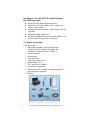
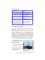
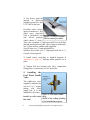
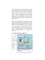
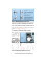
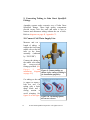
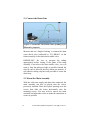
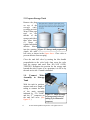
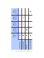
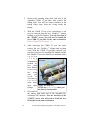
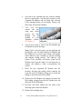
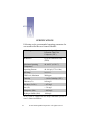
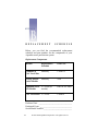
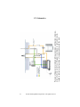
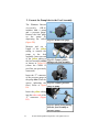
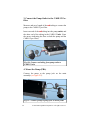
+
Getting Started With
Your
AQUALITE RO/DI Water
Purification System
(In full color at www.aquathin.com)
Includes setup and maintenance information for:
AQUALITE Ultra Deluxe
AN ISO 9001:2008 QMS
REGISTERED /CERTIFIED COMPANY
(IMS 0192 & NQA-12635)
© 2007-2009 Aquathin Corporation. All rights reserved.
Under the copyright laws, this manual may not be copied,
in whole or in part, without the written consent of
Aquathin Corporation.
Every effort has been made to ensure that the information
in this manual is accurate. Aquathin Corporation is not
responsible for printing or clerical errors.
Aquathin Corporation
Aquathin Business Centre
950 South Andrews Avenue
Pompano Beach, Florida 33069
1-800-GO.2.RODI (462-7634) or 1-954-781-7777
Fax: 1-954-781-7336
Email: [email protected]
www.aquathin.com
Aquathin Corporation, the Aquathin Corporation logo,
AQUALITE RO/DI Water Purification System, Platinum
-90, and PSS-90 are trademarks and copyright of
Aquathin Corporation. Product specifications are subject
to change without notice.
Your Authorized Aquathin Dealer Is:
Dealer Name___________________________________
Contact _______________________________________
Address _______________________________________
_______________________________________
Phone _______________________________________
Fax
_______________________________________
Email _______________________________________
2
© 2007-2009 Aquathin Corporation. All rights reserved.
Introduction
Thank You
for your purchase. Aquathin turned
"30 in 2010" to enjoy its Pearl Anniversary and
it’s a great feeling of self satisfaction and accomplishment to be an Authorized Aquathin Dealer. You
could not have picked a better time to consider the
many benefits of becoming a member of the ever
growing Aquathin Family. The Next Quarter Century
Celebration Begins!
Aquathin manufactures a broad spectrum of unique
and patented water purification, softening and filtration systems servicing the residential, commercial
and laboratory markets. Established in 1980,
Aquathin now produces over 70 patented and trademarked devices for markets around the world
through more than 600 Authorized Aquathin Dealers. Aquathin is an E.P.A. Registered manufacturer,
ISO 9001:2008 Certified and recipient of the prestigious President's Excellence Award in Export from
the U.S. Commerce Department and the Nation's
Blue Chip Enterprise Initiative Award from the U.S.
Chamber of Commerce. We have a very impressive
global client list that now includes you and your family. Recently we have launched a project, two years
in the making, for Authorized Aquathin Dealers to
provide total home air and water security...and
more. Visit the Aquathin Allergy Store online at
www.aquathin.com.
3
© 2007-2009 Aquathin Corporation. All rights reserved.
Aquathin does not sell franchises nor do we charge
for territories. We want to make sure that our Dealers are service oriented and knowledge driven. We
know that even though we make the best water
treatment systems in the world, ultimately they are
only as good as the people representing them. And
this is why we make the very best water treatment
Dealers in world. Your local Authorized Aquathin
Dealer has received training and continuous education from Aquathin University. You can be assured
that when you purchase from an Authorized
Aquathin Dealer (or from the factory directly in areas
where we have yet to approve and establish a
Dealer) you are receiving the finest equipment and
technical support this industry is able to offer. Highest quality water treatment systems and support
good enough for my home...my family.
And that is my promise to you! I love my Aquathin!!
FOR THE BEST TASTE IN LIFE &
30 Years Pure Excellence
...and another Quarter Century re-inventing the water industry!
Think Aquathin...AquathinK !!
( visit the NEW www.aquathin.com )
"Alfie"
Alfred J. Lipshultz, President
P.S. Remember...the next best thing to owning an
Aquathin is recommending one to a friend!
4
© 2007-2009 Aquathin Corporation. All rights reserved.
C
5
o
n
t
e
n
t
s
1
Getting Started
2
Getting to Know Your RO/DI System 24
Setting Up Your AQUALITE System
1.Unpack the System
2. Required Tools
3. Planning the Installation
4. Installing the Chrome Faucet Assembly
5. Installing the Feed Water Saddle Valve
6. Installing the Drain Saddle Valve
7. Preparing to Mount the Main Assembly
8. Making the Tubing Connections
9. Connecting Tubing to Speedfit® Fittings
10. Connect Cold Water Supply Line
11. Connect the Drain Line
12. Mount the Main Assembly
13. Prepare Storage Tank
14. Connect Main Assembly to Storage Tank
15. Connect GAC Post Filter
16. Power-up the Main Assembly
17. Connect to Ice Maker – optional
18. Option for Low Source Pressure (PBA-G)
Verify the Tubing and the Flow
Starting Your System
Indicators of System Activity
Operation Procedure
A Look at the Key Components
Aquathin CARB 12 Two-Stage Pre-filter
Granular Activated Carbon
Aquathin Reverse Osmosis Module
Aquathin Deionization Module
Operating Parameters
Pressure
pH
Chlorine and Chloramines
© 2007-2009 Aquathin Corporation. All rights reserved.
7
8
9
10
10
10
11
12
13
14
15
15
16
16
17
17
18
18
18
19
19
20
21
23
24
24
25
25
26
27
27
27
27
3
4
5
Sediment
Iron
Hardness and More
28
28
29
Maintenance And Servicing
31
Exterior Cleaning
Flushing
Filter Replacement
31
31
32
Frequently Asked Questions
37
Limited Warranty
41
What The Warranty Covers
Exceptions To Lifetime Warranty
What We Will Do To Correct An Inconvenience
How State Law Relates To The Warranty
41
41
42
42
A
A
A
A
6
ppendix A - Specifications
43
ppendix B - Replacement Schedule
45
Replacement Components
Maintenance Log
45
46
ppendix C - Connections
47
C1—Sink Mounted Faucet Assembly
C2—John Guest Speedfit® Fitting
C3—AQUALITE Installation Diagram
C4—AQUALITE Installation (with pump)
C5—Schematics
47
48
49
50
51
ppendix D - Optional Pump
52
1. Prepare to Mount the Pump
2. Connect Pump Inlet to Feed Assembly
3. Connect Pump Outlet to CARB 12 pre-filter
4. Mount the Pump
52
53
54
54
© 2007-2009 Aquathin Corporation. All rights reserved.
GETTING STARTED
Thank you for purchasing this quality water purification
system by Aquathin Corporation. The Aquathin
AQUALITE Ultra Deluxe RO/DI is the ultimate
sophisticated state of the art in water purification and
began production in the early 1990's after successful lab
testing and 20 year field experience. This user’s manual
serves for the installation of the AQUALITE Ultra
Deluxe RO/DI. Every Aquathin AQUALITE Series
system combines several efficient methods of water
treatment to achieve a very specific result—pure water
that meets the rigorous standards for biocompatibility.
As the new owner of an Aquathin RO/DI water
purification system there is a totally new experience
awaiting you. You and your family will be amazed at the
delightful new taste of your tap water—it’s like owning
your own personal mountain spring.
This manual provides information about the application
and servicing of your Aquathin water purification system.
Descriptions of the components and their functions will
help to answer frequently asked questions. By thoroughly
reading this manual you will be better able to operate
your new system and perform simple maintenance.
7
© 2007-2009 Aquathin Corporation. All rights reserved.
SETTING UP YOUR AQUALITE SYSTEM
Your Aquathin AQUALITE system requires adequate
water pressure. The AQUALITE operates at 24 volts,
utilizing a compact transformer that accommodates either
110 or 220 volts, so that you can take your system
wherever you move. This unit is designed to operate
within a pressure range of 40–100 PSI. The amount of
purified water produced depends primarily on your water
pressure, temperature, and the amount of Total Dissolved
Solids (TDS). Normal production averages up to 45
gallons (≈ 170 liters) per day. If you plan to install this
unit on a private well system, you should check your
water pressure gauge. If the low pressure setting is less
than 40 PSI, ask a plumber to adjust and raise the
pressure to the minimum level of 40 PSI. An optional
booster pump (PBA-G) is available when source pressure
is severally low. Installation to comply with state and
local laws and regulations.
IMPORTANT NOTE:
For private well owners we recommend that you choose
the AQUALITE Ultra Deluxe with PBA-G booster pump
system which includes a booster pump and is completely
configured at the factory. This eliminates fluctuations in
line or low pressure associated with private wells and
ensures your AQUALITE system operates at peak
efficiency. While 45PSI is enough to produce water with
exceptional purity required for passing Aquathin
standards, you may find water flow to the faucet is less
than optimal, and that your holding tank will not store
much water. (The amount of water stored is a function of
line pressure).
8
© 2007-2009 Aquathin Corporation. All rights reserved.
Installing Your AQUALITE System Requires
the Following Steps:
Install the sink-mounted chrome faucet.
Install the feed water saddle valve to deliver tap
water to your system.
Mount the Frame Assembly to the cabinet sidewall
(optional).
Make the tubing connections.
Install the Platinum Booster Assembly (PBA-G) to
provide ample water pressure (optional).
1. Unpack the System
Contents include:
1. Main filter assembly, with sub-sink frame,
including the RO module, DI module and
Sediment /Carbon pre-filter (CARB 12)
2. Faucet assembly
3. Storage tank
4. Tank ball valve
5. Feed water saddle valve
6. Drain saddle valve
7. GAC post filter (CARB 6)
8. Ice maker tee (optional)
9. Platinum booster assembly, including pump and
pressure gauge (optional)
10. Tubing
Figure 1. Package Contents
9
© 2007-2009 Aquathin Corporation. All rights reserved.
2. Required Tools
Hi Speed Drill
¼" High Speed Drill Bit
½" High Speed Drill Bit
¹⁄16" High Speed Drill
Bit
For porcelain sinks, a
Dremmel® tool and ¾"
silicon carbide grinding
wheel or a Glass & Tile
carbide spade-tipped bit.
#2 Phillips Screw
Driver
Teflon thread tape
Razor knife with fresh
sharp blade
Adjustable (Crescent)
Wrench
For granite countertops, you will need to
have a professional
drill a ½" hole.
3. Planning the Installation
Review the following instructions completely before
proceeding. (See installation diagram on page 49.)
Aquathin AQUALITE systems are comprised of several
compact components which fit easily beneath most
kitchen sinks. We encourage you to establish the desired
location of each of the components before proceeding.
Installing the main assembly against the left sidewall is
recommended whenever possible. The storage tank has
built-in feet for upright positioning and it can be placed
on its side when space is limited. (A stand is included.)
4. Installing the Chrome
Faucet Assembly
1) Select a location for the
faucet on the sink top.
NOTE: Make sure there are
no reinforcing ribs under the
Figure 2. Pure water
sink drilling location.
faucet on sink
10
© 2007-2009 Aquathin Corporation. All rights reserved.
2) Use factory approved
method or approved
plumbing practice to drill
a 7/8" hole in the sink.
Porcelain sinks: factory
approved method is: first
grind away porcelain
with a Dremmel® tool Figure 3. Using a Dremmel
and silicon grinding Tool to remove porcelain
wheel (about ¾" circle).
Then, use a standard ½" high-speed drill bit to drill hole
through metal portion of sink. (insert figures) Alternately,
use a “glass and tile carbide spade tipped bit.”
Acrylic sinks: use ½" high-speed drill bit.
Stainless Steel sinks: use ½" high-speed drill bit or ½"
Greenlee chassis punch.
3) Install faucet according to detailed diagram in
Appendix C1. page 47, insuring rubber gaskets are in
place.
4) Tighten lock nut beneath sink. Save compression
fitting parts for connection to GAC post-filter.
5. Installing the
Feed Water Saddle
Valve
The saddle-type valve
supplied is intended for
use on ⅜" to ½" copper
tubing cold water
supply line. It is not
intended for flex lines.
Figure 4. Feed water saddle
Install on cold water valve.
NOTE: Color coding of tubing
line only!
is for installation purposes.
11
© 2007-2009 Aquathin Corporation. All rights reserved.
Turn off the cold water valve under the sink or the
main valve for the house. Slide clamp over the copper
tubing and tighten screw firmly to hold the clamp in
position. Pierce the copper tubing by turning the
needle valve handle clockwise until it is firmly seated.
The valve is closed in this position. Turn on the MAIN
supply valve to pressurize cold water line.
Immediately check for any signs of leaks. Set aside
compression fittings for later use in connecting feed
tubing to system.
When ready to supply water to the system, turn valve
handle counter-clockwise until fully open. In some
instances the self-piercing valve provided will not be
compatible with your plumbing. We have provided a
feed valve that will satisfy most scenarios. Alternate
parts using standard ¼" compression fittings can be
found at a plumbing supply or at home improvement
stores. On rare occasions, it may be necessary to
contact a plumbing contractor to complete your
installation.
6. Installing the Drain Saddle Valve
The
drain
s a d d l e
assembly
should
be
installed
above the trap
and on the
vertical
or
horizontal
tailpiece. (See
Figure
5).
Refer
to
Figure 6 (next
page)
and Figure 5. Drain Saddle Mounting
Locations
12
© 2007-2009 Aquathin Corporation. All rights reserved.
Figure 6. Mounting the Drain Saddle Valve
follow steps 1 through 4 to mount the drain saddle valve.
NOTE: When installing the Main Assembly, mount the
frame above the position of the drain saddle whenever
possible. (See Figure 11 on page 16).
7. Preparing to Mount the Main Assembly
When possible we
r e c o m m e n d
mounting the main
assembly on the left
sidewall of the
cabinet, but this is
not a requirement.
It is not required
that the system be
mounted at all— Figure 7. Mounting Arrangement
many
o w n e r s in the case of Limited Cabinet
choose to let the Space
main
assembly
stand unsupported on the floor of the cabinet. Mounting
the system as shown in Figure 7 will not only save
cabinet space, but also the brackets on the bottom of the
frame will cradle the tank holding it in position.
13
© 2007-2009 Aquathin Corporation. All rights reserved.
Figure 8. Spacing between keyholes (figure not drawn
to scale)
Install the screws (Figure 8) provided allowing for the
thickness of the frame. (A pilot hole using a 1⁄16" drill bit
is recommended for particle board side-walls.)
NOTE: Do not hang the assembly until tubing
connections have been made (following pages.)
8. Making the Tubing Connections
You have completed the bulk of the installation tasks. All
that remains is connecting tubing between the
components.
The tubing is to be used to:
Connect the feed water saddle valve to the inlet on
the main assembly (indicated by “TO FEED”)
Connect the chrome faucet to the inlet on the main
assembly frame (indicated by “TO DRAIN”)
Connect the tank to the inlet on the main assembly
(indicated by “TO TANK”) and as well to connect
the tank to the faucet through the GAC post filter
(CARB 6).
NOTE: It is important to correctly measure the required
length of the tubing for each connection prior to cutting
the tubing. Additional yellow and red tubing are provided
if you opted for the pump (PBA-G).
14
© 2007-2009 Aquathin Corporation. All rights reserved.
9. Connecting Tubing to John Guest Speedfit®
Fittings
Aquathin systems make extensive use of John Guest
Speedfit® fittings. These high quality components
provide secure, leak free seals and make it easy to
connect and disconnect tubing without the use of tools.
Refer to diagrams on page 48, Appendix C2.
10. Connect Cold Water Supply Line
Measure and cut a
length of tubing to
connect the feed water
saddle valve to the left
inlet on the frame
assembly (indicated
by “TO FEED”).
Connect the tubing to
the saddle valve using
the
compression
fittings provided. (See
figure
9
and
Figure 9. Connect tubing as
installation diagram
shown (color coding of tubing is
on page 49.)
for installation purposes)
Cut tubing so the end
is square to ensure a
leak free seal. Cut
tubing with a fresh,
sharp blade and a
slicing motion to
avoid crimping. See
figure 10 on the right.
15
Figure 10. Cut tubing square;
do not use scissors
© 2007-2009 Aquathin Corporation. All rights reserved.
11. Connect the Drain Line
Figure 11. Drain line connection (color of tubing is for
illustrative purposes)
Measure and cut a length of tubing to connect the drain
water check valve (indicated by “TO DRAIN” on the
frame assembly) to the drain water saddle valve.
IMPORTANT: Be sure to measure the tubing
appropriately before cutting. If the frame of the main
assembly is not above the drain saddle valve, you will
need to loop the tubing as high as possible beneath the
sink. Be sure to allow for this loop when you measure. A
self-adhesive tubing clip has been provided to secure the
drain loop.
12. Mount the Main Assembly
With the cold water supply and drain line connected, the
main assembly can now be placed onto the screws
previously installed. Place the keyhole openings over the
screws then slide the frame horizontally onto the
mounting screws. You may wish to remove the main
assembly and adjust the screws to make the connection as
secure as possible.
16
© 2007-2009 Aquathin Corporation. All rights reserved.
13. Prepare Storage Tank
Remove the plug
on top of the
storage
tank,
revealing an inlet.
Wrap Teflon pipe
tape
on
the
threads of the
storage tank inlet;
then place three
(3) drops of
regular household
chlorine bleach
into the opening. Figure 12. Storage tank preparation
Attach the tank
ball valve as shown in the figure above. Close valve to
prevent chlorine from escaping.
Close the tank ball valve by turning the blue handle
perpendicular to the valve body; then screw the valve
onto the storage tank until firm. DO NOT OVERTIGHTEN. Determine the position for the storage tank
beneath the sink. If space is at a premium, it is OK to lay
the tank on its side. A stand is included.
14. Connect Main
Assembly to Storage
Tank
With the tank in position,
measure and cut a length of
tubing to connect the inlet
of the main assembly
indicated by “TO TANK”
and the “T” connector on Figure 13. Main assembly
the tank ball valve. (See to storage tank (color of
tubing is for illustrative
figure 13.)
purposes)
17
© 2007-2009 Aquathin Corporation. All rights reserved.
15. Connect GAC Post Filter
Refer again to the AQUALITE installation diagram on
page 49 in Appendix C3. The GAC post-filter (CARB 6)
is typically installed just below the faucet assembly and is
easily supported by the tubing and Speedfit® fittings.
Measure and cut a length of tubing to connect the outlet
of the GAC post-filter to the faucet assembly. Placing the
post-filter near the tank will make it easy to service when
needed.
Connect one end of the tubing to the threaded stem of the
chrome faucet assembly using the ¼" compression
fittings provided. (See diagram on page 49 in Appendix
C3.)
Connect the opposite end of the tubing to the outlet of the
GAC post-filter.
Finally, measure a length of tubing to connect the storage
tank to the GAC post-filter.
Leave the handle on
the tank ball valve
closed at this point.
16. Power-up the
Main Assembly
Connect the provided
transformer to the main
assembly as shown.
Figure 14. Transformer connection
17. Connect to Ice Maker – optional
Before connecting the GAC post-filter to the faucet
assembly (as described above), connect the GAC post18
© 2007-2009 Aquathin Corporation. All rights reserved.
filter to the ice maker using
the Ice Maker Tee
provided. (See figure on the
right.)
18. Option for Low
Figure 15. Connect the Ice
Source Pressure
Maker as shown (color of
(PBA-G)
tubing is for illustrative
I f y o u e x p e r i e n c e purposes)
fluctuations in line or low pressure, often associated with
private wells, we recommend that you choose the
AQUALITE with PBA-G booster pump system which
includes a booster pump and is completely configured at
the factory. (The amount of water stored is a function of
line pressure). To setup and install the optional pump,
refer to instructions in Appendix D.
VERIFY THE TUBING AND THE FLOW
Tubing and flow depend on whether you chose to use the
pump.
Without pump:
Cold water enters the main assembly through the “TO
FEED” inlet. The water then passes through to the inlet
of the CARB 12 pre-filter and from the pre-filter to the
RO Module.
The purified water exits the main assembly from the “TO
TANK” outlet and passes through the tank and the
CARB 6 GAC post-filter before reaching the chrome
faucet.
With pump:
Cold water enters the main assembly through the “TO
FEED” inlet. The water then passes through the pump to
19
© 2007-2009 Aquathin Corporation. All rights reserved.
the inlet of the CARB 12 pre-filter before reaching the
RO module.
The purified water exits the main assembly from the “TO
TANK” outlet and passes through the tank and the
CARB 6 GAC post-filter before reaching the faucet.
Congratulations! You have completed the installation of
your Aquathin AQUALITE water purification system.
You are now ready to begin making pure, Aquathin
quality drinking water.
STARTING YOUR SYSTEM
1. Open the chrome faucet on the sink top.
2. Verify the Tank Ball Valve is closed.
3. Slowly open your cold water supply valve. You will
also begin to hear water flowing into the drain.
4. Check the pressure gauge on optional PBA-G.
Record your initial pressure in Appendix B.
5. In approximately 20 minutes you will begin to see
water drip from the faucet.
6. Close the faucet on the sink top, and then quickly
open the Tank Ball Valve to allow the storage tank to
fill. Actual production rate will vary slightly
depending on pressure, but your system will normally
produce up to 45 gallons of water per day, depending
on model. The first tank of water may take longer.
7. DISCARD THE FIRST FULL TANK OF
WATER. Open the faucet and let the water flow
until only a trickle remains. Close the faucet and
allow the tank to fill a second time. You are now
ready to enjoy the great taste of 100% pure, Aquathin
drinking water. (The RO Module contains a
preservative solution that will be flushed after the
first tank of water is produced.)
20
© 2007-2009 Aquathin Corporation. All rights reserved.
IMPORTANT: Monitor your system and check for leaks
frequently over the first week.
Most leaks are attributed to tubing not fully seated inside
the Speedfit® fittings. Remove the red lock clip,
compress the collet, and remove the tubing. Re-insert the
tubing until you feel it bottom out on the tubing end-stop.
Replace the red lock clip. This process solves 99% of
leaking connections. If the leak persists, trim ¼" – ½" off
the end of the tubing and try again.
INDICATORS OF SYSTEM ACTIVITY
The main system has four light indicators on the frame.
These are important indicators of the system activity.
The first green light (from left) indicates that the power
is turned on. This light appears when the system is
running, filling, or flushing. It remains lit even when the
tank is full and when the pressure is low.
The second green light (from left) turns on only when
the tank is full. Therefore, when the tank is full, both the
green lights will be lit.
The first amber light (from left) is lit when the system is
active, i.e. when water is either filling or when the system
is flushing. Therefore, if the tank is full and the system is
idle this light will not be lit.
The second amber light (from the left) is lit only when
the system is flushing; flushing is an automated function
in the AQUALITE Ultra Deluxe.
The red light indicates that the water pressure is low. If
this light is turned on, you may need to use the optional
pump system.
21
© 2007-2009 Aquathin Corporation. All rights reserved.
22
© 2007-2009 Aquathin Corporation. All rights reserved.
Low water pressure
Tank full
System flushing
System running
Green
(power
on)
Green
(storage
tank full)
Amber
(system
on/off)
Amber
(system
flushing)
Red
(low feed
pressure)
OPERATION PROCEDURE
Your Aquathin Auto Power Panel Subsink Reverse
Osmosis / Deionization Water Purification System is self
operational. The exclusive patented power panel does all
the work! Each time the tank calls for water, the system
will self flush the RO Module for 2 minutes and then
manufacture water. Unlike other RO systems, this unique
design helps to preserve the longevity of your RO
Module by removing potentially plaquing debris.
NOTE: Should you leave your residence for a few
days or more, turn off the cold water feed line, unplug
the electric cord, and drain the tank via the faucet.
Repeat the start up procedure when you return.
23
© 2007-2009 Aquathin Corporation. All rights reserved.
GETTING TO KNOW YOUR AQUATHIN RO/
DI SYSTEM
Your Aquathin AQUALITE system combines the three
most effective water purification technologies available.
Alone, each of these methods is highly effective for a
particular group of pollutants—but only when combined
can you be assured of complete removal of all
contaminants. Every system combines Carbon
Adsorption, Reverse Osmosis, and Deionization. By
carefully matching the components utilizing these
methods, we are able to assure your system produces
water which meets or exceeds the standards for
biocompatibility and purity.
A LOOK AT THE KEY COMPONENTS
Aquathin CARB 12 Two-Stage Pre-filter
This fully encapsulated filter module contains a carefully
chosen grade of granular activated carbon to remove
chlorine, chloramines, and other organic contaminants
along with a nominal 10-20 micron sediment filter to
remove silt, sand, rust, or other deposits commonly
found in the feed water supply. This protects the
Aquathin Reverse Osmosis Membrane from particles
24
© 2007-2009 Aquathin Corporation. All rights reserved.
which might clog the pores. This pre-filter has been
carefully selected for its extremely high dirt holding
capacity.
Before water reaches the reverse osmosis module, it is
subjected to a “Aquathin unidirectional” Granular
Activated Carbon pre-filter. Flow is lengthwise, not
radial, for maximum contact time and organic adsorption.
Through the two-stage pre-filter we insure complete
removal of organic contaminates including pesticides,
herbicides, and other hydrocarbon based compounds.
A single gram of steam washed, bituminous grade,
granular activated carbon typically has ≈1500 square
meters of surface area—meaning our 2-stage CARB 12
pre-filter provides over 200 acres (0.81 square
kilometers) of surface area where organic contaminants
dissolved in the water have an opportunity to be adsorbed
and eliminated. This immense GAC surface area also
insures complete and total conversion of chlorine and
chloramines—protecting the Aquathin polyamide—
thinfilm composite (TFC) Reverse Osmosis Module
downstream.
Aquathin Reverse Osmosis Module
A custom designed and extremely efficient High Flow
spiral wound Reverse Osmosis Module produces up to
45gallons (≈170 liters) of purified water per day. The
Aquathin RO Module utilizes the unique properties of a
semi-permeable material which allows passage of pure
water molecules while not allowing dissolved salts,
heavy metals, organics and disease causing water-borne
microorganisms to pass through.
Our extraordinary module is designed to consistently and
significantly reduce the total dissolved solids in the
source water supply by greater than 97%. It also has a
25
© 2007-2009 Aquathin Corporation. All rights reserved.
tremendous capacity to completely reject organic and
biological contaminates, including disease causing waterborne microorganisms. EPA EST. NO. 52531-FL-01
The Aquathin Reverse Osmosis Module used in this
system can tolerate significantly higher concentrations of
oxidizing contaminants like iron and manganese than RO
modules found in other systems, as well as a much higher
degree of hardness. However, there are limitations—the
operating parameters for this module are found in the
Specifications section of this manual.
Aquathin Deionization Module
This stage contains a unique blend of proprietary
deionization resins carefully matched to our Reverse
Osmosis Module and provides superior rejection of
monovalent ions, fluoride, and nitrates; contaminants
only partially removed by reverse osmosis. Including
deionization after reverse osmosis sets Aquathin systems
apart from other ordinary RO systems.
Following the DI resins, there is even more granular
activated carbon to polish the product water for a clean,
fresh taste. The flow rate at this stage provides
tremendous contact time to assure complete removal of
any remaining organic contaminates.
The final stages of our proprietary DI module are
included to prevent the reverse migration of contaminates
into the system. These stages further separate Aquathin
systems from other brands. After carefully combining the
previous components it is essential to integrate these
stages to ensure 99.999% removal of bacteria, cyst, and
virus (EPA EST. No. 52531-FL-01). These stages also
prevent any contaminants from entering the system via
the faucet.
26
© 2007-2009 Aquathin Corporation. All rights reserved.
OPERATING PARAMETERS
To insure proper operation of your AQUALITE system,
it is advisable to collect the following information about
your water supply. This information is generally
available from your municipal water department, and in
many cases is available from the website of your local
Department of Public Works.
Pressure
In order to overcome the natural osmotic force, adequate
water pressure must be available from your water supply.
The osmotic force is directly proportional to the
concentration of dissolved solids in the water. When the
water pressure is equal to the osmotic force, there will be
no movement of pure water molecules across the semipermeable reverse osmosis module. A minimum of 45
PSI is required. (If your water pressure is below 45 PSI, a
booster pump is available. If you are on a private well,
have your plumber raise the minimum pressure above 45
PSI.)
In general, the higher the pressure (up to 100 PSI), the
better the performance of the module at rejecting
contaminants.
pH
The Aquathin HRO TFC module will hold up very well
when the pH of the feed water is between 2 and 11.
Water supplies with pH over 11 are very rarely, if ever,
found. (Chlorine bleach has a pH of ~11.5.)
Chlorine and Chloramines
Chlorine is the most common substance added to
municipal water supplies. Its purpose is to eliminate
biological growth (i.e. chlorine is toxic). Regulations
usually require there be residual chlorine when water
27
© 2007-2009 Aquathin Corporation. All rights reserved.
reaches your tap. Typically, the residual concentrations of
chlorine in household water range from 0.5 to 1.0 parts
per million (ppm).
Besides being toxic, chlorine and chloramines will
degrade the TFC Reverse Osmosis Module. Therefore, it
is essential to remove chlorine from your feed water
before it reaches the RO Module. Your Aquathin RO/ DI
system includes a pre-filter containing a special grade of
grade of Granular Activated Carbon (GAC) which will
very effectively remove chlorine and chloramines from
your tap water. It is important to replace the pre-filter
annually to insure no chlorine is reaching the membrane.
Sediment
In areas with very high sediment concentrations the
Aquathin pre-filter may clog prematurely. If the pre-filter
becomes clogged, you will likely notice a decrease in the
production rate from your system. In areas with very high
sediment concentrations, it may be necessary to replace
the pre-filter on a semi-annual basis.
Over the course of one year, the sediment filter will
typically become significantly discolored. This is not
cause for alarm. If you notice pressure at the gauge has
dropped significantly below your initial observations,
consider changing this filter to restore adequate pressure
and improve overall system performance.
Iron
Iron concentrations greater than 0.1 mg/l can degrade
overall system performance. If your water supply has iron
concentrations above 0.1 mg/l, pretreatment is
recommended for ordinary RO systems. Your patented
Aquathin process will tolerate up to 3 ppm iron.
28
© 2007-2009 Aquathin Corporation. All rights reserved.
Hardness and More
Two thirds of the water on earth is groundwater. As it
travels through rock and soil it picks up particles of
calcium, magnesium, iron, lead, and other minerals. For
85% of the country, that translates into “hard water”.
“Hardness” refers to the amount of calcium and
magnesium in the water and is measured in grains per
gallon (gpg). The following guide defines your water’s
hardness based on two different measurements. Our test
determines the grains of hardness that can easily be
converted into the ppm.
Description
Grains of
Hardness
Parts per
Million
Laundry
Detergent
Required
Soft (ideal)
0.0—1.0
0—18
1/4
dispenser
Slightly
Hard
1.0—3.5
18—60
1/4
dispenser
Moderately
Hard
3.5—7.0
60—120
1/2
dispenser
Hard
7.0—10.5
120—180
1/2
dispenser
Very Hard
10.5—
over
180—
over
Full
dispenser
Most of the problems associated with hard water are
economical in nature. Hardness causes unsightly soap
scum on fixtures, water spots on glasses and whitish scale
deposits in your tubs and showers. Hard water means you
use more soap and cleaning agents because they first
have to “clean” the water before they clean anything else.
29
© 2007-2009 Aquathin Corporation. All rights reserved.
H
ere is a little additional information about the
ordinary RO systems sold in hardware stores and
wholesale clubs:
1.
They state their systems must be installed on water
with less than 10 grains of hardness. Otherwise you
need an expensive water softener just for the RO
system. Your Aquathin can be installed on hard
water up to 25 grains due to the patented flush.
2.
There is a disclaimer that those units may not be
installed on microbiologically unsafe water. But
would that not be a reason one would purchase a
system? Your Aquathin will remove disease
causing waterborne microorganisms.
3.
Their warranty is one year, but does not cover the
RO module, yet that is the heart of the unit. When
service is needed, you must ship the system out of
town. Some require the module to be replaced every
6 months according to them. Your Aquathin carries
a Lifetime Warranty except for normal filter
changes and abuse.
Y
ou originally invested in your Aquathin to provide
your family the very best in total home water
security. There is hardly anything in this world that a man
could not make a little worse or a little cheaper, and the
people who consider price alone are this man’s lawful
prey. It's like this: we would rather explain price once
than apologize for poor quality and service the rest of our
life. In 1980 Aquathin made the decision at the onset; that
we would never sacrifice or lower quality for price… too
much depends on it. Would you prefer that your family
drink from a system whose poor technology and cheap
design allows them to continue to consume
contaminates… or a product that provides the safest and
most pure drinking and cooking water available?
I LOVE MY AQUATHIN!
30
© 2007-2009 Aquathin Corporation. All rights reserved.
MAINTENANCE
AND
SERVICING
Minimal work is required to keep your Aquathin
AQUALITE system in peak operating condition. Simply
replace the filter modules as recommended. These simple
steps will insure your unit consistently produces ultrapure water meeting Aquathin standards.
Take care of your Aquathin system and it will provide
many years of healthy drinking and cooking water for
your entire family.
1. Exterior Cleaning
The exterior surface of your Aquathin can be kept
looking like new by occasionally cleaning the surfaces
with a soft cloth. Great care was taken in the choice of
material for your unit, but the cabinet cannot withstand
harsh chemicals or solvents. Use a mild, non-abrasive
dish washing detergent or diluted spray cleaner to remove
smudges or food stains, then rinse and dry the surface.
Use of abrasive scouring powders or glass cleaning
products containing ammonia are not recommended.
2. Flushing
Flushing is the single most important maintenance
function needed to keep your system operating at peak
31
© 2007-2009 Aquathin Corporation. All rights reserved.
efficiency and it extends the service life of the reverse
osmosis module. This simple operation has been
automated in the Aquathin AQUALITE Ultra Deluxe.
If your unit has not been used for more than one week
(e.g. while you are on vacation), drain the storage tank
(use the water for watering plants, etc.) then flush the
module for 5-10 minutes as described above.
3. Filter Replacement
After 12 months of use, it is time to replace the 2-stage
Aquathin CARB 12 pre-filter and the 4-stage Aquathin
Deionization (DI) Module to insure your system is
producing water within RO/DI parameters. After 2-3
years (depending on the level of contaminants in water),
the Reverse Osmosis (RO) Module should be replaced,
along with the post filter (CARB 6). Replacement
modules can be ordered directly from your local
Authorized Aquathin Dealer.
1.
2.
3.
4.
Remove the contents from beneath the kitchen sink
where the Aquathin assembly is located.
Choose a work area with a large flat surface such as
a kitchen table.
Place a soft clean towel on the working surface – it
will absorb the small amount of water that will spill
from the modules as they are changed out, and it will
protect the surface of both the table and your
Aquathin cabinet.
Turn the unit over on the towel, exposing the filter
modules
Removing the Aquathin Modules
Before proceeding, refer to Appendix C2 on page 48.
Remove the tubing connections to the Aquathin Modules
(CARB 12, DI Module and RO Module) – NOTE: refer
to the figure 16 on how to release tubing and follow the
32
© 2007-2009 Aquathin Corporation. All rights reserved.
Figure 16: Speedfit Push-in Fittings
procedure outlined:
1.
The first module you need to remove is the 2-stage
Aquathin CARB 12 pre-filter. It is supported by two
“Double C” clamps which are attached to the
Aquathin RO Module. At one end of the CARB 12
pre-filter the feed water tube enters from the feed
assembly. At the other end a piece of tubing
connects to the feed water inlet of the RO Module.
The tubing is attached to the module using a unique
push-in fitting system (figure 16). This system is
designed to make connecting and disconnecting
filter modules very easy while insuring a water tight
connection.
The “collet” assembly will securely hold the tubing
in place under normal operating conditions. Pulling
on the tubing will not cause it to release, instead the
“grip” of the collet will become more secure. An Oring behind the collet assures a leak free seal.
To insure your system will be water-tight even after
being shipped across country, we have inserted
small plastic retaining clips on each fitting. These
are easily removed with your fingers or, if grabbing
the clip is difficult, you may wish to use a pair of
needle-nose pliers.
33
© 2007-2009 Aquathin Corporation. All rights reserved.
2.
Remove the retaining clips from each end of
Aquathin CARB 12 pre-filter, then remove
tubing itself. You will feel some resistance as
tubing slides away from the O-ring inside
fitting.
3.
With the CARB 12 free of its connections, it can
now be removed from the two “Double C” clamps
holding it to the RO Module. Note the direction of
the “FLOW” arrow. You will need to install the
new CARB 12 pre-filter in the same orientation.
Refer to Figure 18 for steps 4—6.
4.
After removing the CARB 12, you can easily
remove the two “Double C” clamps and set them
aside. With the CARB 12 pre-filter removed, you
now have access to the Aquathin DI Module and the
RO Module. These two modules are attached with a
c u s t o m
c l a m p (5) remove tubing from
DI Module
arrangement
secured by
two wing
nuts. Before
removing
the
wing
nuts,
you
need
to
disconnect
remove
(4) remove Double C
s e v e r a l (6)
black tube from RO
clamps
more tubes
from their Figure 18: Steps 4-6
fittings.
NOTE: the green arrows show you
the flow for each module
Disconnect
the tubing from each end of the Aquathin Deionization (DI) Module. Note the direction of the
“FLOW” arrow. You will need to install the new
DI module in the same orientation.
5.
34
the
the
the
the
© 2007-2009 Aquathin Corporation. All rights reserved.
6.
One end of the Aquathin Reverse Osmosis module
has two connections—one blue tube connects to the
Aquathin DI Module, and one black tube connects
to the Aquathin drain valve assembly. Remove the
black tube from the RO Module.
7.
You can now
remove the two
wing nuts which
secure the RO
Module and DI
module to your
Aquathin cabinet. Figure 19: Remove the two
wing-nuts
See figure 19.
8.
You are now ready to remove the RO Module and
DI Module from the housing.
Note: If this is the first time you are replacing the
DI Module, you will find both the DI Module and
RO Module are secured to the clamps with double
sided adhesive tape (installed to prevent shifting
and damage during transit). The adhesive will
release if you carefully, and slowly, rotate the DI
Module away from the clamp. It is not necessary to
replace the adhesive when re-assembling the
system.
9.
Place the new Aquathin DI Module into the
housing. Re-insert the tubing which connects the
reservoir to the DI Module, taking care to attach the
tubing to the outlet end of the module.
10. Replace the RO Module and clamps. Re-insert the
blue tubing coming from the RO Module into the
inlet end of the DI Module.
11. Re-insert the black tubing into the brine water
discharge port on the RO Module.
12. Replace the retaining clips.
35
© 2007-2009 Aquathin Corporation. All rights reserved.
13. Replace the two wing-nuts which secure the RO/DI
clamp.
14. Snap the two “Double C” clamps back onto the RO
Module.
15. Place the new CARB 12 Pre-filter into the clamps,
being sure the “FLOW” arrow points the same
direction as noted in step 3 above.
16. Re-insert the feed water tube from the hose
assembly into the inlet end of the CARB 12. Reinsert the tubing from the RO Module inlet into the
outlet end of the CARB 12. Replace the retaining
clips.
17. When all filters have been replaced and all tubes
have been reconnected, hook the unit up to the
faucet and turn on the water. Let the unit produce
water for 10–15 minutes then drain the water, invert
the unit, and inspect for leaks. If any water appears
at any of the tubing connections, remove the
retaining clip, remove and re-insert the tubing.
Replace the retaining clip. (A leaking connection is
extremely rare.)
18. You can now return the unit to service. Let the
reservoir fill and discard the first tank of water (use
it to water plants, etc.) You are now ready to again
enjoy great tasting, pure Aquathin RO/DI water for
another 12 months!
36
© 2007-2009 Aquathin Corporation. All rights reserved.
FREQUENTLY
ASKED
QUESTIONS
Q: How long will my Aquathin CARB 12 pre-filter last
before it needs to be replaced?
A: Under most normal city water conditions, the
Aquathin Carb 12 is designed to function properly for 12
months, and should be replaced annually. Sediment
concentrations vary greatly between municipal systems
so there is no way of determining the lifetime of a filter
without knowing more about the feed water. In some
very rare cases, it may be necessary to replace the prefilter more frequently.
Q: How long will my CARB 6 post-filter last before they
need to be replaced?
A: Your Aquathin AQUALITE system has been designed
to operate within a wide range of tap water conditions.
These conditions vary greatly across municipalities, so it
is difficult to state precisely how long your post-filter will
last. We have designed the system so that under the most
extreme conditions your post-filter will still be
performing correctly after 12 months of use. The CARB
6 post-filter should be replaced when changing the RO
module (once in 2-3 years). This will insure your system
is consistently performing as designed, producing ultrapure water that meets the standards for biocompatibility.
37
© 2007-2009 Aquathin Corporation. All rights reserved.
Q: How long will my reverse osmosis module last?
A: The module’s life depends on the water conditions as
listed in the specification section of this manual. If all
these conditions are met, the life of the module is
generally 2–4 years. If a module fails or its performance
becomes reduced before this time, the cause can usually
be traced to tap water conditions outside the
specifications or failure to flush.
Q: How do I know if there is a problem with the module?
A: The best method is to measure the resistivity
(conductivity) of the RO water and compare it to the tap
water. You can invest in a reliable and inexpensive
resistivity meter available from your Authorized
Aquathin Dealer or you can send them samples for
analysis. (Poor rejection rates may also be an indication
of a clogged pre-filter, so check that filter first.) A large
increase in the production rate is also an indication of
module failure, and can often be traced to the module
having been subjected to either freezing or hot water.
Q: How can I monitor the performance of the unit?
A: Your Authorized Aquathin Dealer will register your
warranty card and purchase with Aquathin Corporation.
Every year upon the anniversary of your installation,
Aquathin Corporation and your Aquathin Dealer will
mail or email an Annual Service Reminder to have your
system inspected and serviced if necessary. Also, with
identical feed water pressure, the production rate should
remain fairly constant. If your system begins to produce
water at a much faster rate, the RO module may have
failed. If your system is producing water at a much lower
rate, replacing the pre-filter is often indicated. To monitor
the overall system rejection rate, the best method is to
obtain either a resistivity meter or TDS meter from your
Authorized Aquathin Dealer.
38
© 2007-2009 Aquathin Corporation. All rights reserved.
Q: Will I lose valuable minerals when I drink purified
water?
A: No, the body does not readily assimilate the minerals
found in drinking water. We obtain the majority of our
minerals from the foods we eat. There are many more bio
-available “chelated” minerals in a piece of organic fruit
or a serving of organic vegetables than in several gallons
of water.
Q: Will pure water leach minerals from my body?
A: This question reflects one of the common myths that
are found in the water industry. It has no basis in fact or
physiologic science. Pure water does perform a valuable
function by helping the body eliminate wastes and
unused minerals that have been excreted from cellular
tissues, but it does not “leach” minerals out of the cells.
This false claim was probably first made by companies
wanting to boost sales of filters incapable of removing
dissolved minerals and dangerous heavy metals. ASK
your Authorized Aquathin Dealer for a copy of “5th
Functions of Water”.
Q: Will hot water ruin my RO module?
A: YES! Hot water over 100° F will damage the module
and void your warranty. Make sure you use only COLD
water in your Aquathin system.
Q: How should I store my purified water?
A: Ask your Authorized Aquathin Dealer about clear
Aquathin polycarbonate bottles.
Q: How should I store my unit when not in use?
A: If your unit is out of service for several days (while
you are vacationing, for example) no special precautions
are required. However, we do recommend you to flush
the unit for 10-15 minutes and discard the first tank of
water when you return the system to production.
39
© 2007-2009 Aquathin Corporation. All rights reserved.
Q: How long does it take to make a tank of water?
A: The rate your system produces water is dependent
upon several factors including source water pressure,
temperature, and the amount of total dissolved solids
(TDS). We rate our modules very conservatively, and the
AQUALITE systems come with a up to 45 gallons of
water per day module.
Q: When system enters flush mode, it makes noise. Is
this normal?
A: When your system is flushing, water is flowing to the
drain much faster than normal production mode. The
check valve will sometimes chatter with the increased
flow, and this can be heard as a hum or rattle. When your
system is first put in service, there may be air in the lines
that can also cause noise from the system. After a few
days the noise typically will go away.
Q: How can I keep informed about Aquathin?
A: “Splash News Bulletin”, “Forum Q&A”, “Allergic
Reaction”, “Biz Bank”, “Tech Bank”, and “Quote Bank”
are all FREE services to all Authorized Aquathin Dealers
and their Customers to keep you abreast of technology
updates and industry news.
Email Aquathin at [email protected] to subscribe.
Visit www.aquathin.com.
40
© 2007-2009 Aquathin Corporation. All rights reserved.
LIMITED WARRANTY
Aquathin Corporation warrants to the original owner of
each AQUALITE water purification system to be free
from defects in materials and workmanship for as long as
you own the product.
What The Warranty Covers
Full Lifetime Warranty on all parts (excluding normal
module changes or abuse). 2 years on electronic components.
Your AQUALITE pure water appliance is a sophisticated
water purification system. Failure to follow the maintenance schedule or use other-than genuine Aquathin components will void the exclusive lifetime warranty.
Exceptions to Lifetime Warranty
The Lifetime Warranty does not include damage caused
by or resulting from unreasonable use, including failure
to provide reasonable maintenance, or incidental or consequential damages, such as water damage, mold or damage to appliances, fixtures or other equipment.
Warranty will be void if product failure or damage is due
to any of the following:
1. Misuse, misapplication, neglect (e.g. inadequate fil41
© 2007-2009 Aquathin Corporation. All rights reserved.
2.
3.
4.
ter changes), alteration, hot feed water, freezing, or
accident.
Improper installation, operation, or servicing.
Use only Genuine Authorized Aquathin components
to assure efficiency and to maintain your Warranty.
No one is authorized to change or add to this Warranty.
What We Will Do To Correct An Inconvenience
Upon notice, we will repair or replace covered defective
parts, free of charge. If it is necessary to return the product to an Aquathin Dealer for service, the buyer must pay
for any shipping or travel costs. Aquathin Dealer will pay
for any return shipping charges in the U.S. for parts or
products covered under the Warranty.
An Aquathin Dealer will furnish any factory labor to
make repairs on parts or products returned to the factory
that are covered under the Warranty.
How State Law Relates To The Warranty
Some states do not allow the exclusion or limitation of
incidental or consequential damages, so the above limitation or exclusion may not apply to you. This warranty
applies to the original purchaser and gives you specific
legal rights. You may also have other rights which vary
from state to state.
42
© 2007-2009 Aquathin Corporation. All rights reserved.
SPECIFICATIONS
Following are the recommended operating parameters for
our custom rolled Reverse Osmosis Module:
Module type
Aquathin Spiral Wound
Polyamide Thin Film
Composite (TFC)
Production
Up to 45 Gallons-Per-Day
(GPD)
Maximum Operating
Temperature
40–100° F (4–38° C)
Operating Pressure
40–100 psi (2.75–6.9 bar)
pH Range
2.0–11.0
TDS Level, Maximum
2000 ppm
Turbidity
< 1.0 Net Turbidity (NTU)
Chlorine (Cl2)
0.00 mg/l *
Hardness (CaCO3)
< 427 mg/l
Iron (Fe)
< 3.0 mg/l
Manganese (Mn)
< 0.05 mg/l
Hydrogen Sulfide (H2S)
0.00 mg/l
*Every system is equipped with our unique combination pre-filter to
remove sediment and chlorine.
43
© 2007-2009 Aquathin Corporation. All rights reserved.
You can obtain specifics about your water supply from
either your local water department or your local Authorized Aquathin Dealer. If the parameters of your water do
not fall within the specified ranges as noted above, please
contact your local Aquathin Dealer for further options.
Production is rated at optimum temperature of 70° F, 60
PSI, and 500 ppm TDS. Actual production will vary depending on local temperature, pressure, and TDS level.
Low tap water pressure will reduce the volume and quality of the water produced by your system. In low pressure
situations (<40 PSI) RO/DI values cannot be assured.
The addition of a booster pump (PBA-G) is strongly recommended.
ALWAYS USE COLD WATER—hot water will damage
the TFC membrane.
The unit must not be allowed to freeze. Freezing water
will expand inside the modules—damaging the membrane and potentially rupturing the filter housings. Damage of this type will void the warranty.
This system has been tested according to WQA S-300 for
reduction of TDS. The concentration of TDS in water
entering the system was reduced to less than or equal to
the permissible limit for water leaving the system, as
specified in WQA S-300. Testing was performed under
standard laboratory conditions. Actual performance may
vary. Follow installation procedures and scheduled
maintenance for optimum performance.
44
© 2007-2009 Aquathin Corporation. All rights reserved.
REPLACEMENT
SCHEDULE
Below you can find the recommended replacement
schedule and part numbers for the components of your
Aquathin water purification system.
Replacement Components
Module
Replacement
Schedule
Order No.
Sediment &
GAC Pre-Filter
Annually
CARB 12
4-Stage Deionization Module
Annually
ADI
Aquathin Series 2-3 Years (as
needed)
RO Module
HRO or XF-HRO
GAC Post-Filter 2-3 Years
CARB 6
Purchase Date: _________________________________
Purchased From: ________________________________
Serial/Model Number:____________________________
45
© 2007-2009 Aquathin Corporation. All rights reserved.
Maintenance Log
Module Replaced
46
Date
© 2007-2009 Aquathin Corporation. All rights reserved.
C1. Sink Mounted Faucet Assembly
47
© 2007-2009 Aquathin Corporation. All rights reserved.
C2. Anatomy of John Guest Speedfit ® Fitting
Tubing End-stop
Collet
Internal O-Ring
1)Insert tubing into fitting,
2)Past the Internal O-Ring,
3)Until it bottoms out
against the tubing end-stop
Pull on tubing to ensure a
secure connection, then
slide red Lock Clip between collet and fitting.
Remove the red Lock-Clip
Push Collet up against body of the
fitting, which will release the internal
teeth.
While compressing Collet,
pull out the tubing.
48
© 2007-2009 Aquathin Corporation. All rights reserved.
C3. AQUALITE Installation Diagram
49
© 2007-2009 Aquathin Corporation. All rights reserved.
C4. AQUALITE Installation Diagram
(with optional pump)
50
© 2007-2009 Aquathin Corporation. All rights reserved.
Purpose of diagram is to indicate tubing connection and location of components relative to water flow. Diagram is not drawn to scale and is not intended to indicate actual position of components beneath the sink.
C5. Schematics
51
© 2007-2009 Aquathin Corporation. All rights reserved.
INSTALLING THE OPTIONAL PUMP
1. Prepare to Mount the Pump (PBA-G)
Identify a space to place the pump. The pump can be
placed on the floor for convenience, preferably in close
proximity to the main assembly. This will ensure that the
tubing is kept to a minimum and is neatly arranged.
The pump may be mounted as well, however, do not
mount the pump with screws until the tubing is
completed.
In the main assembly, the CARB 12 pre-filter is
connected to the feed assembly and to the RO Module,
such that the flow is indicated coming from the feed
water assembly to CARB 12 pre-filter to the RO Module.
Remove the tubing
that
makes
the
connection between
the feed assembly and
the CARB 12 prefilter; the pump will be
connected in between
Fig. D1: Remove tubing that
these (figure D1).
connects CARB 12 to feed
assembly
52
© 2007-2009 Aquathin Corporation. All rights reserved.
2. Connect the Pump Inlet to the Feed Assembly
The Platinum Booster
Assembly
(PBA)
includes both a pump
and a pressure gauge.
Remove the blue plugs
on the pump by
depressing the collets Fig. D2: Remove the plugs
(figure D2).
Measure and cut a
length of the yellow
tubing to connect the
pump to the feed
assembly. Insert one end
of the yellow tubing to Fig. D3: Connect yellow
the feed assembly outlet tubing to the feed assembly
as shown in Figure D3
(where the CARB 12
pre-filter was previously
connected).
Insert the “T” connector
of the pressure gauge in
the pump inlet (Note the
arrows indicating the Fig. D4: Connect pressure
flow). Refer to figure gauge to pump
D4.
Insert the yellow tubing
into the other end of the
“T” connector. (Figure
D5)
Fig. D5: Insert yellow tubing
from the feed assembly to
pressure gauge
53
© 2007-2009 Aquathin Corporation. All rights reserved.
3. Connect the Pump Outlet to the CARB 12 Prefilter
Measure and cut a length of the red tubing to connect the
pump to the CARB 12 pre-filter.
Insert one end of the red tubing into the pump outlet, and
the other end of the tubing in the CARB 12 inlet. (Note
the arrows indicating the flow on both the pump and the
CARB 12 pre-filter).
Fig. D6: Connect red tubing from pump outlet to
CARB 12 inlet
4. Mount the Pump (PBA)
Connect the pump to the pump jack on the main
assembly (see figure D7).
Fig. D7: Connect pump to pump jack on main frame
54
© 2007-2009 Aquathin Corporation. All rights reserved.
With the pump inlet, outlet and pump jack connected to
the main assembly, the pump can now be mounted with
screws in the position previously identified. (A pilot hole
using a 1⁄16" drill bit is recommended for particle board
side-walls.)
NOTE: you may rotate the face of the pressure gauge, if
needed, for easier reading.
55
© 2007-2009 Aquathin Corporation. All rights reserved.
EPA EST. NO. 52531-FL-01
56
© 2007-2009 Aquathin Corporation. All rights reserved.


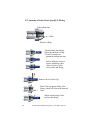
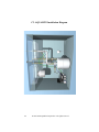
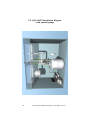


![Comité international «LE BROUILLON DE DISCUSSION» [v1.0]](http://vs1.manualzilla.com/store/data/006427750_1-98d4cf7e9ae9eae2ca262dfaece03607-150x150.png)