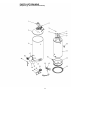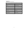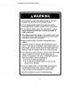
1
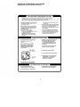
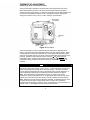
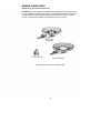
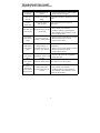
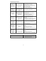
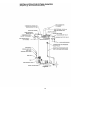
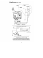
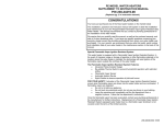
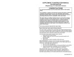
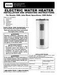
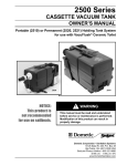
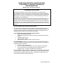
SUPER HIGH EFFICIENCY WATER HEATERS SUPPLEMENT TO INSTRUCTION MANUAL P/N 238-44219-00 (Replaces pg. 2 in instruction manual.) CONGRATULATIONS! You have just purchased one of the finest water heaters on the market today! This installation, operation and instruction manual will explain in detail the installation and maintenance of your new High Efficiency Flammable Vapor Ignition Resistant Gas Water Heater. We strongly recommend that you contact a plumbing professional for the installation of this water heater. We require that you carefully read this manual, as well as the enclosed warranty, and refer to it when questions arise. If you have any specific questions concerning your warranty, please consult the plumbing professional from whom your water heater was purchased. For your records, we recommend that you write the model, serial number and installation date of your water heater in the maintenance section in the back of this manual. Special Flammable Vapor Ignition Resistant System: This water heater is equipped with a Flammable Vapor Ignition Resistant System. In the event of improper usage or storage of gasoline or other flammable materials in the location where the water heater is installed, the technology will resist ignition of the flammable vapors outside the confines of the water heater. The Flammable Vapor Ignition Resistant System Features: Advanced Flame Arrestor Design Re-settable Thermal Switch to prevent burner/pilot operation with restricted airflow Flammable Vapor Sensor Automatic Ignition Device Sight Window to observe operation of pilot and burner FOR YOUR SAFETY: Activation of the Flammable Vapor Ignition Resistant System occurs when flammable vapors are drawn into the water heater and are combusted. If flammable vapors are detected: Do not try to light any appliance. Do not touch any electrical switch; do not use any phone in your building. Leave the premises and immediately call the fire department from a neighbor’s phone. Follow the fire department’s instructions. Once the flammable vapor has been evacuated, contact your plumbing professional or the manufacturer for further instructions. Replacement of a Flammable Vapor Ignition Resistant System equipped water heater due to a flammable vapor shutdown is not covered under the terms of the limited warranty. 238-48703-00B 12/12 Minimum Clearances (Replaces pg. 9 in instruction manual.) WARNING Failure to adhere to these installation and operating instructions may create a hazard to life and property and will nullify the warranty. This installation must allow access to the front of the water heater and adequate clearance must be provided for servicing and operating this water heater. The water heater may be installed on either a combustible or non-combustible floor. If the water heater is to be installed directly on carpeting, it must be installed on top of a metal or wood panel (or equivalent) extending beyond the full width and depth of the water heater by at least 3 in. (7.6 cm) in any direction or, if the appliance is to be installed in an alcove or closet, the entire floor must be covered by the panel. If the rating plate or the label on the front of the heater specifies minimum clearances less than those listed below, the water heater must be installed in accordance with the minimum clearances listed on the rating plate or the label on the front of the heater. If it is necessary to install this water heater in an alcove, use the clearances listed in Figure 1. Figure 1. Minimum Clearances for an Alcove Installation. 2 Venting (Replaces pg. 10 in instruction manual.) WARNING The venting system must be installed properly following all local codes or in the absence of local codes, the latest edition of the National Fuel Gas Code (ANSI Z223.1latest edition), or in Canada, The Natural Gas and Propane Installation Code (B149.100 latest edition). Failure to properly install the venting system could result in property damage, personal injury, or death. WARNING Carefully inspect the venting system of a replacement water heater installation before connecting to the venting system. All joints in the vent connector must be securely fastened with screws and fit tightly together. Inspect the venting system for signs of deterioration (rust and perforation) and replace any sections that are not in good condition. The chimney must be lined and in good condition. Check to make sure the venting system is properly sized for the water heater. If the venting system was previously sized for another gas appliance that has been removed, the venting system may now be too large. Refer to the latest edition of the National Fuel Gas Code (ANSI Z223.1latest edition), or in Canada, the Natural Gas and Propane Installation Code (B149.100 latest edition) for the correct sizing of venting systems and common venting with another gas appliance. Do not vent this water heater into the venting system of another gas appliance designed to vent under positive pressure. The water heater should be installed as close as practical to the venting system to minimize the vent connector length required. Refer to local codes for the distance limitations on vent connector lengths. At the completion of the water heater installation, the burner and venting system must be checked for proper operation with all other commonly vented appliances in operation. Check for spillage of flue products around the outside relief opening of the draft hood after several minutes of operation. The flame from a match should be drawn into the draft hood. Do not use the water heater or connected equipment if spillage is detected until the problem is corrected. Refer to the latest edition of the National Fuel Gas Code, or in Canada, the Natural Gas and Propane Installation Code for complete details on the “Procedure to Be Followed to Place Equipment in Operation”. This water heater has been shipped with a draft hood for which it was designed with reference to the horizontal and vertical planes. If removed, the draft hood must be replaced in the same position and secured to the blower draft hood bracket. NOTICE This water heater is equipped with a draft hood. This water heater can be vented using single wall or double wall vent connector pipe. This water heater may be vented into Type B vent or a masonry chimney. This water heater can use either 3” or 4” venting. Refer to the National Fuel Gas Code (latest edition) vent tables, using “NAT” columns to determine appropriate vent configuration. 3 Lighting and Shutdown Instructions (Replaces pg. 18-19 in instruction manual.) 4 THERMOSTAT ADJUSTMENT (Replaces pg. 20-21 in instruction manual.) The thermostat dial is adjusted to its lowest setting when shipped from the factory. When adjusting the thermostat, it should be remembered that lower temperature settings are more energy efficient. To adjust the thermostat, turn the dial clockwise until the minimum acceptable temperature is set. It is suggested that the starting point setting not exceed the 120°F (49°C) or “HOT” setting on the thermostat. Figure 2. Gas Valve. The thermostat dial is set to its lowest temperature setting when shipped from the factory. Remember that lower temperature settings are more energy efficient. Adjust the temperature by turning the thermostat dial. It is suggested that the starting point setting not be greater than the “Hot” mark on the thermostat dial (approximately 120°F [48.9°C]). Rotate the thermostat dial counter-clockwise to decrease the temperature setting. Rotate the thermostat dial clockwise to increase the temperature setting. Adjust the dial until the minimum acceptable temperature is achieved. DANGER Hotter water increases the risk of scald injury. Scalding may occur within five (5) seconds at a temperature setting of 140F (60C). To protect against hot water injury, install an ASSE approved mixing valve in the water system. This valve will reduce point of discharge temperature by mixing cold and hot water in branch water lines. A licensed plumbing professional or local plumbing authority should be consulted. Note: This water heater is equipped with an energy cut out device to prevent overheating. Should overheating occur or the gas supply fails to shut off, turn off the manual gas control valve to the water heater, and call a qualified service technician. Note: Whenever the water heater is filled with cold water, condensate will form on the cool tank surface and drops of water will fall on the hot burner and combustion chamber surfaces producing a “sizzling” noise. Condensation is normal and does not indicate a leak. It will disappear when the tank becomes heated. 5 BURNER FLAME CHECK (Replaces pg. 22 in instruction manual.) Steel Burner: These models are equipped with self adjusting air mixture and do not have an adjustable air shutter (See Figure 3). At periodic intervals, a visual check of the main burner and pilot flames should be made to determine if they are burning properly. The main burner flame should light smoothly from the pilot. Figure 3. Burner and Pilot Assembly Used. 6 TROUBLESHOOTING CHART (Replaces pg. 26-27 in instruction manual.) LED Status Control Status None (LED not on Electrical pow er not or flashing) present One short flash Stand-by mode, every four Thermostat is satisfied (no seconds faults) Alternates bright Thermostat calling for and dim heat (no fault) (heartbeat) Short flash once every second Tw o flashes, three second pause Three flashes, three second pause Four flashes, three second pause Five flashes, three second pause Six flashes, one flash, three second pause (Soft Lockout) Weak pilot signal on last call for heat Probable Cause 1. Control pow er sw itch in " OFF" position 2. Supply voltage interrupted Temperature demand is satisfied (no call for heat) Tank temperature below setpoint of thermostat 1. Unstable pilot 2. Pilot tube block or restricted 3. Oxidation build-up on pilot electrode 4. Wire damage to pilot assembly or bad connection at gas valve 1. Pressure sw itch tubing kinked or blocked Pressure sw itch not 2. Blocked pressure tap on sw itch w orking - closed position 3. Faulty pressure sw itch Pressure sw itch or temperature sw itch not w orking - open position 1. Vent blockage or improper vent configuration 2. Pressure sw itch tubing kinked or blocked 3. Blow er not spinning to speed 4. Faulty pressure sw itch Excessive tank 1. Thermal w ell sensor out of calibration temperature, system must 2. Faulty gas valve be reset False pilot flame present Failed to light pilot, system resets after (5) minutes Pilot valve stuck in open position 1. Unstable pilot 2. Pilot tube block or restricted 3. Oxidation build-up on pilot electrode 4. Wire damage to pilot assembly or bad connection at gas valve 7 Troubleshooting continuedSix flashes, three flashes, three second pause (Soft Lockout) 1. Unstable pilot 2. Pilot tube block or restricted 3. Oxidation build-up on pilot electrode 4. Wire damage to pilot assembly or bad connection at gas valve 5. Insufficient combustion air Pilot flame extinguished, system auto resets after (5) minutes Six flashes, four Undesired false pilot flame flashes, three sensed, system auto Pilot valve stuck in open position second pause resets Seven flashes, three second pause Flammable vapor sensor or resettable thermal sw itch fault detected, see w arning label Eight flashes, one flash, three second pause Flammable vapor sensor out of specification, possible short 1. Flammable vapor present 2. Flammable vapor sensor exposed to excessive moisture 3. Flammable vapor sensor exposed to extreme ambient temperature 4. Re-settable thermal sw itch open 1. Flammable vapor sensor out of specification 2. Possible short in flammable vapor sensor or re-settable thermal sw itch w iring Eight flashes, tw o flashes, three second pause 1. Damage to thermal w ell w ires 2. Thermal w ell sensor resistance out of Temperature sensor fault range 3. Replace thermal w ell Eight flashes, three flashes, three second pause 1. Verify control is not w et or physically Gas valve electronics fault damaged detected 2. Reset control on/off sw itch 3. Replace electronic module if 8-3 error persists Eight flashes, four flashes, three second pause 1. Verify control is not w et or physically damaged 2. Reset control on/off sw itch 3. Replace gas control if 8-4 error persists Gas valve fault detected Fault Probable Cause 1. Insufficient combustion air 2. Flammable vapors present Re-settable Thermal Switch Tripped (Open) 8 Troubleshooting continuedControl Sequence of Operation Start up Sequence Upon powering up, the control checks for the presence of the flammable vapors, if the resistance is in the expected range the control will begin normal operation after 5 to 8 seconds. Normal Heating Sequence 1. The thermostat senses a call for heat. 2. The control checks the pressure switch condition. 3. If the pressure switch is open, the control sends power to the blower motor. 4. The blower starts moving combustion air through the combustion system. 5. The pressure switch closes. 6. The control senses the closed pressure switch and starts the ignition process by providing a spark at the pilot electrode and allowing gas to flow to the pilot. 7. When the pilot is lit, the gas control senses the pilot flame and opens the main gas valve. 8. The main burner is lit. 9. The main burner and blower continue to operate until the thermostat is satisfied. 10. The blower operates for a short post purge period before shutting down. 11. The water heater remains in the stand-by mode until the next call for heat. 9 INSTALLATION FOR POTABLE WATER (Replaces pg. 28 in instruction manual.) Figure 4 10 PARTS LIST DRAWING (Replaces pg. 29 in instruction manual.) Figure 5 11 PARTS LIST (Replaces pg. 30 in instruction manual.) PART NAME AND DESCRIPTION 1. Draft hood 15. Right side inner door 2. Jacket head 15A. Re-settable Thermal Switch 3. Jacket 16. Left side inner door 4. High Efficiency Blower 17. Blower harness 5. Heat trap (outlet) 18. Main burner feedline 6. Anode Outlet Device 19. Gas control 7. Heat trap (inlet) 20. FV sensor / RTS wire harness 8. Baffle 21. FV sensor clip 9. Diptube 22. FV sensor 10. T&P valve 23. Outer door 11. Tank 24. Burner 12. Combustion chamber 25. Orifice 13. Pedestal base 26. Pilot assembly 14. Drain valve 12 THE FOLLOWING INSTRUCTIONS ARE FOR INSTALLATION OF: GAS WATER HEATERS SUITABLE FOR WATER (POTABLE) HEATING AND SPACE HEATING (Replaces pg. 31 in instruction manual.) All piping components connected to this water heater for space heating applications must be suitable for use with potable water. In Massachusetts, space heating piping length must not exceed 50 feet. 1. Toxic chemicals, such as those used for boiler treatment, must not be introduced into potable water used for space heating. 2. This water heater must not be connected to an existing heating system or component(s) previously used with a non-potable water heating appliance. 3. When the system requires water for space heating at temperatures higher than required for other means, such as an ASSE approved mixing valve must be installed to temper the water for those uses in order to reduce the scald hazard potential. Please refer to Figure 6 for suggested piping arrangements. Figure 6 13 (In addition to the instruction manual.) 14 Electrical Connections (In addition to the instruction manual.) All electrical wiring and connections must be in accordance with the National Electric Code ANSI/NFPA No. 70-Latest Edition, or the Canadian Electrical Code C22.1-Latest Edition, and any local codes which may apply. The water heater must be electrically grounded. If a flexible line cord and plug is permitted by local code, then provide a (3) three wire grounding type receptacle within 6 ft. (1.9 m) of the water heater and use the flexible cord provided. Do not plug the line cord into a receptacle that can have its power supply interrupted by a switch that is used to turn on and off lights. Turn off the water heater gas control and disconnect power to the water heater. If wiring in conduit is required, cut the flexible line cord at least 6 in. (15.2 cm) from the bushing. Unscrew and remove the blower junction box assembly. Pull the cord into the junction box assembly housing. Cut the three wires from the line cord at the bushing inside of the housing. Enlarge the hole in the back of the blower junction box assembly to receive a 1” electrical conduit connector. Wire the power supply into the circuit at the appropriate locations. Replace the blower junction box assembly and re-install the screws previously removed. Connect power to the water heater. Turn the water heater gas control back on. CAUTION Turn off or disconnect the electrical power supply to the water heater before servicing. Label all wires prior to disconnection when servicing controls. Wiring errors can cause improper and dangerous operation. Verify proper operation after servicing. 15 Wiring Diagram (In addition to the instruction manual.) 16