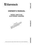
1
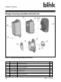
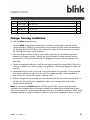
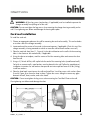
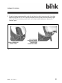
Wall Mount Charging System Installation Manual Simply Smart. 2010-2011 by Electric Transportation Engineering Corporation. All rights reserved. No part of the contents of this document may be reproduced or transmitted in any form or by any means without the express written permission of Electric Transportation Engineering Corporation, dba ECOtality North America™. The contents of this document have been verified by the manufacturer to be consistent with the described components; however, inconsistencies sometimes occur. Such inconsistencies should be brought to the attention of an ECOtality North America representative. Changes to this manual may be made at any time without notice. Disclaimer of Consequential Damages ECOtality North America is not responsible for the use or application by any person of the materials in this manual. ECOtality NA is not responsible for damages, either direct or consequential, arising out of or relating to the use or application of these materials. Blink™, Blink Network™ the Blink™ logo, and ECOtality North America™ are all trademarks of ECOtality, Inc. ANSI® is a registered trademark of the American National Standards Institute. Fluke® is a registered trademark of Fluke Corporation. IEC® is a registered trademark of the International Electrotechnical Commission. IEEE™ is a trademark of the Institute of Electrical and Electronics Engineers, Inc. SAE J1772™ is a trademark of SAE International®. TORX® is the registered trademark of Textron Inc. Rev # Changes Made 1.1 Initial public release; first version with UL amendments 1.2 Verso layout; addition of RJ-45 documentation; various minor corrections 1.3 Final changes inserted for release The current version of this manual is available online at www.blinknetwork.com/help Electric Transportation Engineering Corporation dba ECOtality North America 430 S. 2nd Avenue Phoenix, Arizona 85003-2418 ii IM0001_L2_R_WMv1.3 888-998-BLINK www.ecotalityna.com Contents IMPORTANT SAFETY INSTRUCTIONS ............................................................. 1 Federal Communications Commission (FCC) Statement ............................................................. 3 Guidelines and specifications ...................................................................... 4 Applicable codes and standards ............................................................................................ 4 Installer/contractor notes ....................................................................................................... 4 Customer responsibility ......................................................................................................... 5 Tools required for installation ................................................................................................. 5 Meters ............................................................................................................................. 5 Hand tools ....................................................................................................................... 5 Installer-supplied items ....................................................................................................... 5 blink features and specifications............................................................................................. 5 Features ........................................................................................................................... 5 Specifications ................................................................................................................... 6 Charger assembly layout ............................................................................ 7 Installation ................................................................................................. 8 Shipping box contents .......................................................................................................... 8 Charger housing assembly and cord reel .............................................................................. 10 Charger housing installation ................................................................................................ 11 Cord reel installation .......................................................................................................... 13 Connecting power to the blink .................................................................. 16 Input power ....................................................................................................................... 16 Connecting the blink ........................................................................................................... 16 Connecting the blink to a LAN via Ethernet (optional) ............................................................. 20 Calibrating the blink touch screen ........................................................................................ 22 IM0001_L2_R_WMv1.3 iii Figures Figure 1 – blink Installations, Typical .......................................................................................... 7 Figure 2 — Shipping Box Contents ............................................................................................ 8 Figure 3 – Hardware Packet Contents ........................................................................................ 9 Figure 4 – Charger Housing Assembly and Cord Reel................................................................ 10 Figure 5 – Charger Assembly Installation .................................................................................. 12 Figure 6 – Cord Reel Installation .............................................................................................. 13 Figure 7 – Cord Reel Cover Installation .................................................................................... 14 Figure 8 – Cord Reel Vehicle Connector ................................................................................... 15 Figure 9 – Housing Cover Removal .......................................................................................... 17 Figure 10 – Supply Circuit Port ................................................................................................ 18 Figure 11 – Service Wiring Terminals ...................................................................................... 18 Figure 12 – Bezel Installation .................................................................................................. 19 Figure 13 – Security Seal ........................................................................................................ 20 Figure 14 – Location of RJ45 (Ethernet) Port .............................................................................. 21 Figure 15 – Closed RJ45 (Ethernet) Port .................................................................................... 21 Figure 16 – Open RJ45 (Ethernet) Port ..................................................................................... 21 iv IM0001_L2_R_WMv1.3 IMPORTANT SAFETY INSTRUCTIONS SAVE THESE INSTRUCTIONS Before using the blink charging system, read all of these instructions, as well as the WARNING and CAUTION markings in this document, on the blink unit, and on your vehicle. Consult the following symbols and related instructions for the actions necessary to avoid hazards. WARNING: Used when there is a risk of personal injury WARNING: RISK OF ELECTRIC SHOCK – Used when there is a risk of electric shock WARNING: RISK OF FIRE – Used when there is a risk of fire CAUTION: Used when there is a risk of damage to the equipment WARNING: RISK OF ELECTRIC SHOCK Basic precautions should always be followed when using electrical products, including the following: a. Read all the instructions before using this product. b. This device should be supervised when used around children. c. Do not put fingers into the electric vehicle connector. d. Do not use this product if the flexible power cord or EV cable is frayed, has broken insulation, or any other signs of damage. e. Do not use this product if the enclosure or the EV connector is broken, cracked, open, or show any other indication of damage. f. MODEL WE-30K/48K GROUNDING INSTRUCTIONS: (Cord-connected models) This product must be grounded. If it should malfunction or break down, grounding provides a path of least resistance for electric current to reduce the risk of electric shock. This product is equipped with a cord having an equipment grounding conductor and a grounding plug. The plug must be plugged into an appropriate outlet that is properly installed and grounded in accordance with all local codes and ordinances. IM0001_L2_R_WMv1.3 1 WARNING: RISK OF ELECTRIC SHOCK Improper connection of the equipment-grounding conductor can result in a risk of electric shock. Check with a qualified electrician or serviceman if you are in doubt as to whether the product is properly grounded. Do not modify the plug provided with the product – if it will not fit the outlet, have a proper outlet installed by a qualified electrician. g. MODEL WE-30C/48C GROUNDING INSTRUCTIONS: (Permanently connected model) This product must be connected to a grounded, metal, permanent wiring system; or an equipment-grounding conductor must be run with the circuit conductors and connected to the equipment grounding terminal or lead on the product. WARNING: RISK OF ELECTRIC SHOCK Do not touch live electrical parts. Properly install and ground this equipment according to this installation manual, as well as national, state and local codes. Incorrect connections may cause electric shock. Disconnect input power before installing or servicing the equipment. WARNING: Models WE-30K/48K – Indoor use only Cord-connected models of this equipment are intended for indoor use only. WARNING: This equipment is intended only for charging vehicles that do not require ventilation during charging. Please refer to your vehicle’s owner’s manual to determine its ventilation requirements. WARNING: RISK OF FIRE To reduce the risk of fire, follow these installation guidelines: Install blink on a wall constructed of material resistant to combustion. A typical example of material resistant to combustion is plasterboard (drywall) over wood framing. Other examples of materials resistant to combustion include brick, concrete, or metal. CAUTION: Incorrect connection may cause damage to the blink charging system. 2 For permanently-connected installations, use wire size and temperature rating as required by local code. Ground blink properly using equipment ground lug. Refer to the label in charger housing identifying service wiring terminal connections. For cord-connected installations, use cord set supplied with the unit only. Use only NEMA 6-50R receptacle for cord connection. IM0001_L2_R_WMv1.3 Federal Communications Commission (FCC) Statement NOTE: This equipment has been tested and found to comply with the limits for a Class B digital device, pursuant to Part 15 of the FCC Rules. These limits are designed to provide reasonable protection against harmful interference in a residential installation. This equipment generates, uses and can radiate radio frequency energy, and if not installed and used in accordance with these instructions, may cause harmful interference to radio communications. If this equipment does cause harmful interference to radio or television reception, which can be determined by turning the equipment off and on, the user is encouraged to try to correct the interference by one or more of the following measures: Reorient or relocate the antenna. Increase the separation between the equipment and the receiver. Connect the equipment to an outlet on a circuit different from that to which the receiver is connected. Consult the dealer or an experienced radio/TV technician for help. This device complies with Part 15 of the FCC Rules. Operation is subject to the following conditions: 1. This device may not cause harmful interference, and 2. This device must accept any interference received, including interference that may cause undesired operation. IM0001_L2_R_WMv1.3 3 Guidelines and specifications This Installation Manual describes how to properly install blink Model WE-30C/K and WE-48C/K Electric Vehicle Supply Equipment (EVSE), referred to as the “blink” throughout this document. Applicable codes and standards The installer or contractor is responsible for obtaining and becoming familiar with the following publications. Installer or contractor work and material shall comply with the local municipality’s currently adopted versions of: National Electric Code Municipal, county, and state building codes and standards Occupational Safety and Health Administration (OSHA) Uniform Building Code Other relevant codes and standards that apply to the installation of structural components and electrical equipment Installer/contractor notes The installer or contractor selected to install the blink Model WE-30C/K and WE-48C/K charging systems, including electrical connections, shall conform to the following general notes: 4 Installation shall be performed as described in the electrical plans and approved drawings. All work shall comply with the local municipality’s currently adopted version of the National Electric Code and Building Code. Labor and materials not specifically described, which are incidental to installations and without which a satisfactory job cannot reasonably be completed, are a part of this installation work. All materials used in the installation shall be new and UL-listed and labeled where required. The installation of AC power circuits and circuit disconnects is not included in this work. Such work must be performed by a certified electrical contractor. It shall be the installer’s or contractor’s responsibility to carefully read this entire installation manual and associated drawings and sketches to determine his/her responsibilities. Failure to do so shall not release the installer or contractor from doing the work in complete accordance with this document. During performance of the work and after all requirements of this installation manual and associated details are fully completed, ECOtality NA and/or the customer shall have the option to inspect the work. IM0001_L2_R_WMv1.3 The installer or contractor shall not modify or otherwise alter blink equipment in any manner other than specifically authorized by this installation manual. Unauthorized modification to the blink equipment voids the manufacturer’s warranty. Customer responsibility The customer is responsible for contracting with a certified electrical contractor to perform all electrical work, including connections at the blink, supply circuit, and main service panel. Tools required for installation Meters Current Clamp Meter (with 600 A MAX AC/DC) (Recommend: Fluke 336) Digital Multimeter (1000V MAX DC/AC) (Recommend: Fluke 87V) ® Hand tools Drill bit, 3/16-inch Hammer Pencil/marker Slotted and TORX -head screwdrivers Wrench, 10 mm Torque wrench ® Installer-supplied items Service wiring to blink Conduit and fittings (1-inch trade size), except for cord-connected units blink features and specifications Features Certified to UL 2594 – Electric Vehicle Supply Equipment Charge circuit interruption device (CCID20) Ground monitoring circuit Nuisance-tripping avoidance and auto re-closure Cold load pickup (randomized auto-restart following power outage) Certified energy and demand metering Wireless IEEE 802.11g IM0001_L2_R_WMv1.3 5 LAN capable Web-based bi-directional data flow Cord management system Power cord for connection to NEMA 6-50R receptacle (WE-30K and WE-48K only) Specifications Model Input Voltage WE-30C/K WE-48C/K 208-240 VAC +/•10% (120 VAC to GND) Single (3-wire) Input Phase 60 Hz Frequency Input Current 30 Amps (maximum); configurable to 12A, 16A, or 24A 48 Amps (maximum); configurable to 12A, 16A, 24A, or 30A Breaker Size 40 Amps; Available settings: 15A, 20A, 30A, or 40A 48 Amps; Available settings: 15A, 20A, 30A, 40A, or 60A Output Voltage Output Phase Pilot Connector/Cable Cord Length (output) 6 208-240 VAC +/•10% Single SAE J1772™ compliant SAE J1772™ compliant; UL-rated at 30A maximum 18 feet (approximate) Cord Length (input) 1 foot (WE-30K and WE-48K only) Exterior Dimensions Charger assembly: 18” wide x 22” high x 5-9/16” deep Cord reel: 18” diameter Temperature Rating •22 °F (•30 °C) to +122 °F (+50 °C) Enclosure NEMA type 3R sun- and heat-resistant Mounting Wall mount IM0001_L2_R_WMv1.3 Charger assembly layout The charger assembly should be mounted on the wall in close proximity to the vehicle stall and at a location where the 18-foot charging cord can be easily connected to the vehicle charging port without the cord stretching taut and/or presenting a trip hazard. The charger assembly must be mounted at a height (minimum 18 inches [460 mm] above floor) where the panel display can be easily seen and monitored by the operator. A height of 60 inches (152 cm) to the center of the display is suggested. The cord reel can be mounted below or in another location near the charger assembly that best accommodates the user’s preferences and comfort. The charger assembly and cord reel may be installed on adjacent walls (corner mounted). For cordconnected blinks (Models WE-30K and WE-48K), there must be sufficient space allowed between the charger assembly and mounting of the cord reel for installation of the 6-50R receptacle. . WARNING: RISK OF FIRE This equipment has arcing or sparking parts that must not be exposed to flammable vapors. This equipment must be located at least 18 inches (460 mm) above the floor. Figure 1 – blink Installations, Typical IM0001_L2_R_WMv1.3 7 Installation WARNING: RISK OF FIRE To reduce the risk of fire, install blink on a wall constructed of a material resistant to combustion such as plasterboard (drywall) over studs, 16 inches on center. The blink kit supports installation of the charger assembly over a wood-framed wall (studs on 16-inch centers), with or without plasterboard (drywall) covering. If the assembly is to be installed on a brick or concrete wall, anchors (not supplied) of an appropriate size suitable for the ¼-inch lag screws and wall material must be used. WARNING: Suitable wall anchors (not supplied) for brick or concrete walls must withstand a pull-out force of 80 lb (36 kg) per anchor, without damaging the wall mounting. Shipping box contents 1. Cord reel 2. Cord reel cover 3. Cord reel cleat 4. Charger housing assembly (with 18-foot charging cord) 5. Hardware packet Figure 2 — Shipping Box Contents 8 IM0001_L2_R_WMv1.3 The blink is shipped in an over-pack box containing two cartons, one with the charger housing assembly and the second with the cord reel. The top carton in the over-pack box contains the cord reel mounting cleat, the cord reel, and cord reel cover. The bottom carton contains the charger housing assembly (with 18-foot charging cord) and hardware packet. The 18-foot charging cord is attached at the bottom right of the charger housing assembly. In addition, the cord-connected (Models WE-30K and WE-48K) will also have a 1-foot power cord attached at the bottom left of the assembly (not shown). Contents of the hardware packet include: o P/N 11-031-0564 — ¼-inch hex-head lag screws (qty. 8) o P/N 11-452-0163 — ¼-inch washers (qty. 8) o P/N 11-356-0273 — M6 x 20 hex-head bolts (qty. 3) Figure 3 – Hardware Packet Contents IM0001_L2_R_WMv1.3 9 Charger housing assembly and cord reel Figure 4 – Charger Housing Assembly and Cord Reel Item # Part Number Description 10 Qty 1 11-357-0277 Torx-head screw (T30) 2 2 20-030-0001 Bezel 1 3 11-356-0273 M6 x 20 hex-head bolt 8 4 20-180-0001 Charger housing cover 1 5 11-031-0564 ¼-inch lag screw 8 6 11-452-0163 ¼-inch washer 8 7 20-180-0001 Charger unit and base 1 8 09-068-0001 Output cord (part of charger unit) (not shown) 1 IM0001_L2_R_WMv1.3 Item # Part Number Description 9 Qty 20-071-0001 Cord reel cover 1 10 20-043-0001 Cord reel 1 11 20-349-0001 Cord reel cleat 1 12 — Power cord (part of WE-30K & WE-48K charger units ONLY) (not shown) 1 Charger housing installation To install the blink charger housing: 1. Open the blink shipping box and remove the two cartons containing the cord reel and the charger assembly. Unpack the cartons and lay out the contents (the two cartons are attached by the charging cord; DO NOT allow excess strain on the cord). Check for all contents as listed in the Shipping box contents section on page 8. 2. With the charger assembly set flat on a work table, remove the two Torx-head screws at the bottom of the charger assembly. Carefully pull up on the bezel to remove the bezel from the housing cover. Pull at the top of the bezel to disengage the two pins from the grommets in the base plate. 3. Choose an appropriate place on a wall for mounting the charger housing assembly. Refer to the Charger assembly layout section on page 7 for guidelines in locating the charger assembly and cord reel. 4. Locate and mark the centers of two studs in the mounting area if the assembly is being mounted on a typical wood-framed wall. (Omit this step if the charger assembly is being mounted on a brick or concrete wall and wall anchors are being used.) 5. Place the charger housing assembly in the desired location on the wall with the mounting holes in the base over the marked studs, if applicable. Make sure the charger housing assembly is positioned level and plumb. Note: For cord-connected blinks (Models WE-30K and WE-48K), space must be allowed for installation of a receptacle below the charger assembly when mounting the assembly and the cord reel (refer to Figure 5 for recommended mounting dimensions). A corded unit requires a NEMA 6-50R receptacle mounted in a metal 5S deep box. Make sure to orient the receptacle as shown in Figure 5. IM0001_L2_R_WMv1.3 11 Figure 5 – Charger Assembly Installation 6. Using the housing assembly as a template, mark the centers of the four mounting holes and remove the housing assembly from the wall. 7. Using a 3/16-inch drill bit, drill a pilot hole for each of the mounting holes (wood-framed wall). For brick or concrete walls, metal anchors must be placed in the wall. Follow the manufacturer’s installation instructions for wall anchors that provide a minimum pull-out force of 80 lbs (36 kg) per anchor; install four anchors. 8. Place the charger housing assembly back in position on the wall and install four ¼-inch lag screws with washers (Items 5 and 6, Figure 4) to secure the housing assembly in place. Tighten the screws enough to remove any gaps between the wall, housing base plate, washer, and screw head. NOTE: If there are irregularities in the wall surface, it may be necessary to place a shim (not supplied) behind one or more of the mounting holes to avoid distorting the charger housing base plate. 12 IM0001_L2_R_WMv1.3 WARNING: All four lag screws (and anchors, if applicable) must be installed to prevent the charger assembly from pulling out of the wall. CAUTION: Do not over-tighten the lag screws when mounting the charger housing assembly on the wall. Over-tightening can deform and damage the housing base plate. Cord reel installation To install the cord reel: 1. Choose an appropriate place on the wall for mounting the cord reel assembly. This can be below or to either side of the charger assembly. 2. Locate and mark the centers of two studs in the mounting area, if applicable. (Omit this step if the charger assembly is being mounted on a brick or concrete wall and wall anchors are used.) 3. Place the cord reel cleat (Item 11, Figure 4) in the desired location on the wall with the mounting holes in the cleat over the marked studs, if applicable. 4. Using the cleat as a template, mark the centers of the four mounting holes and remove the cleat from the wall. 5. Using a 3/16-inch drill bit, drill a pilot hole for each of the mounting holes (wood-framed wall). For brick or concrete walls, metal anchors must be placed in the wall. Follow the manufacturer’s installation instructions for wall anchors that provide a minimum pull-out force of 80 lbs (36 kg); install four anchors. 6. Place the cleat back in position on the wall and install four ¼-nch lag screws with washers (Items 5 and 6, Figure 4) to secure the cleat in place. Tighten the screws enough to remove any gaps between the wall, cleat, washer, and screw head. CAUTION: Do not over-tighten the lag screws when mounting the Cord Reel Cleat on the wall. Over-tightening can deform and damage the cleat. Figure 6 – Cord Reel Installation IM0001_L2_R_WMv1.3 13 NOTE: If there are irregularities in the wall surface, it may be necessary to place a shim (not supplied) behind one or more of the mounting holes to avoid distorting the cleat. 7. Place the cord reel in position on the cleat. Using a socket wrench with extension, install three M6 hex-head bolts (Item 3, Figure 4) to attach the reel to the cleat. Tighten the bolts to 35–38 in-lb (4.0–4.3 Nm). 8. Align tabs on the cover with the seven slots in the cord reel and firmly push in on the cover to attach it to the cord reel. The tabs will snap into place to secure the cover. Figure 7 – Cord Reel Cover Installation Note: The cover may be removed by inserting a small screwdriver blade into the slot from the inner side of the reel rim to release each tab. 14 IM0001_L2_R_WMv1.3 9. Wrap the charging cord around the cord reel and place the vehicle connector end in the holder at the center of the reel. DO NOT force the connector strain relief past the cord retention fingers on the reel. Lift the connector up and into the reel so that only the cord passes between the retention fingers. Figure 8 – Cord Reel Vehicle Connector IM0001_L2_R_WMv1.3 15 Connecting power to the blink Input power IMPORTANT: Electrical power to the blink must be installed by a certified electrical contractor who is familiar with local codes and standards that apply to the installation of structural components and electrical equipment. Minimum size and color-coding requirements must be in accordance with any applicable state or local code, and the National Electrical Code. Voltage/Phase 208-240 VAC/1 phase (120 VAC to GND) Rated Current 30 Amps (maximum); 12A, 16A and 24A available (WE-30C/K) 48 Amps (maximum); 12A, 16A, 24A and 30A available (WE-48C/K) Circuit Rating 40 Amps; settings at 15A, 20A and 30A available CAUTION: The blink EVSE’s factory default current setting is 30 amps. If the device is connected to a lower current setting, a qualified blink technician must adjust the device settings and reset the unit before use. Connecting the blink WARNING: RISK OF ELECTRIC SHOCK Verify that electrical power to the blink input power wiring is disconnected. Electric shock can kill! NOTE: The following procedure covers the installation of a blink that is being hard-wired to the main service panel. This procedure does not apply to the optional cord-connected wall-mount blinks. Cord-connected blinks require the installation of a NEMA 6-50R receptacle in close proximity to the charger housing assembly. For these installations, insert the power cord into the 6-50R receptacle and then test the blink using ECOtality’s Car-in-a-Box equipment. Refer to the blink Car-in-a-Box Operator’s Manual (OM0002_CIB) for more information. 16 IM0001_L2_R_WMv1.3 To connect the blink to the power supply: 1. Remove five M6 hex-head bolts (Item 3, Figure 4); then, remove the charger housing cover from the charger assembly. DO NOT remove the four lag screws securing the charger assembly base to the wall. Figure 9 – Housing Cover Removal 2. Slide a 1-inch trade-size fitting (not provided), appropriate to the conduit type used, over the end of the service wiring. IM0001_L2_R_WMv1.3 17 Figure 10 – Supply Circuit Port 3. Insert the supply circuit conductors through the knockout in the metal housing bracket. Pull enough wiring through to allow for connection to the knockout and ground terminals. 4. Position the 1-inch fitting in the knockout and secure in place using a metal lock ring. Figure 11 – Service Wiring Terminals 18 IM0001_L2_R_WMv1.3 CAUTION: Be careful to not disturb factory wiring when making supply circuit wiring connections within the charger housing. 5. Connect the AC supply conductors (L1 and L2) to the upper two terminals in the terminal block (Figure 11) at the lower left of the charger assembly. 6. Connect the ground wire to the service ground terminal (Figure 11) at the lower right of the charger assembly. 7. Remove and discard the protective film on the touch screen. 8. With the service wiring complete, place the housing cover in position on the charger assembly and install five M6 hex-head bolts (Item 3, Figure 4) to secure the cover in place. Tighten the bolts to 35-38 in-lb (4.0-4.3 Nm). 9. Align the pins at the top of the bezel with the two grommets in the charger assembly base plate and seat the bezel over the housing cover. Figure 12 – Bezel Installation 10. Install two Torx-head screws (Item 1, Figure 4) at bottom to secure the bezel to the charger housing. IM0001_L2_R_WMv1.3 19 11. Test the blink using ECOtality’s Car-in-a-Box equipment. Refer to the blink Car-in-a-Box Operator’s Manual (OM0002_CIB) for more information. Figure 13 – Security Seal NOTE: The blink will make an audible “click” each time that power starts flowing from the blink to the Car-in-a-Box, and again when power stops flowing. This is a normal sound for the blink to make. 12. When the test is successfully completed and if required, install a security seal (not provided) at the bottom of the housing cover. Connecting the blink to a LAN via Ethernet (optional) A small percentage of blink owners will choose to connect their blink to the Internet over a local area network (LAN). The blink includes an RJ45 (Ethernet) port for the physical connection; the connection is then configured during the Network Setup process, which will generally be performed by the blink owner. Refer to the blink Wall Mount Charging System Owner’s Manual for more information about configuring a blink network connection. 20 IM0001_L2_R_WMv1.3 Figure 14 – Location of RJ45 (Ethernet) Port Figure 15 – Closed RJ45 (Ethernet) Port CAUTION: Figure 16 – Open RJ45 (Ethernet) Port The Ethernet port delivered with the blink charging system is intended for indoor use only (such as in a garage). Contact the blink Call Center for information on the additional requirements for a safe outdoor Ethernet connection. To physically connect the blink to a LAN via Ethernet: 1. Unplug the black plastic cap on the RJ45 port, located on the bottom of the charger assembly between the two knockouts. Refer to the figures above. 2. Plug in the customer-supplied Ethernet cable. IM0001_L2_R_WMv1.3 21 Calibrating the blink touch screen The first time you start up the blink charging system, a calibration screen appears, with a small plus sign (+) in one corner. To calibrate the touch screen: 1. Touch the plus sign (+). A plus sign (+) appears in the next corner. 2. Touch the plus sign (+) and repeat three more times as the plus sign moves to the next two corners and then to the center of the screen. 3. A circle () appears in one corner. Touch the circle. Repeat this step three times as the circle moves to each corner. 4. A Calibration Complete message appears in the center of the screen. Touch this message to continue. The Welcome to blink screen appears. Refer to the blink Wall Mount Charging System Owner’s Manual to learn how to configure and use the blink charging system. 22 IM0001_L2_R_WMv1.3 Index B blink charger assembly · 7 charger housing · 11 cord-connected · 1, 2, 5, 7, 9, 11, 16 features · 5 specifications · 6 Building codes · 4 C Calibrate touch screen · 22 Charger assembly · 7 Charger housing · 11 Codes and standards · 4 Cord-connected unit · 1, 2, 5, 7, 9, 11, 16 E Electric shock · 1 Ethernet · 20 Ethernet port · 21 H Hand tools · 5 Hardware packet · 9 Height charger assembly · 7 I Installation bezel · 19 charger housing · 11 cord reel · 13 cord reel cover · 14 L LAN · 20 Local area network · 20 M N NEC · 4 O OSHA · 4 P Parts shipped · 10 Phase input · 6 output · 6 R RJ45 port · 20, 21 S Safety instructions · 1 Service wiring terminals · 18 Shipping box · 8 Supply circuit port · 18 T Touch screen calibrate · 22 U Uniform Building Code · 4 V Ventilation · 2 Voltage input · 6 output · 6 W Warnings · 1 Meters · 5 23 IM0001_L2_R_WMv1.3 430 S. 2nd Avenue Phoenix, Arizona 85003-2418 888-998-BLINK (2546) www.ecotalityna.com 2010-2011 by Electric Transportation Engineering Corporation. All rights reserved. blink™, blink Network™, and the blink logo are all trademarks of ECOtality, Inc. OM0001_L2_R_WMv1.3 2/15/2011