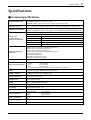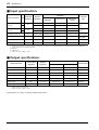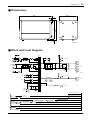
1
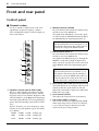
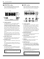
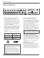
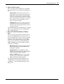
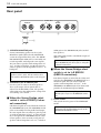
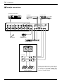
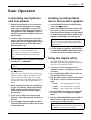
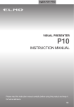
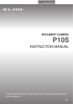
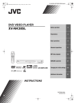
Owner’s Manual
SEE REAR PANEL CAUTION.
1
2
HIGH
3
HIGH
4
HIGH
5
6
HIGH
HIGH
7
HIGH
8
HIGH
POWER
HIGH
VOCAL
–15
+15
MID
–15
+15
MID
–15
+15
LOW
–15
+15
MID
–15
+15
LOW
–15
+15
–15
+15
LOW
–15
+15
MID
MID
–15
+15
–15
+15
LOW
LOW
–15
+15
MID
–15
+15
MID
–15
+15
LOW
–15
+15
L HALL
MID
–15
+15
LOW
–15
+15
S HALL
+6
+3
0
–5
–10
–12
•
6
•
0
•
6
•
+12
–12
•
6
•
0
•
6
•
+12
125
250
500
1k
2k
4k
PHANTOM
+48V
ON
OFF
8k
LOW
LIMITER
–15
+15
MONI
–15
+15
MONI
0
10
EFFECT
0
10
EFFECT
0
10
PAN
L
R
+15
0
10
0
10
L
R
+15
0
10
0
10
L
R
+15
0
10
0
10
L
R
+15
0
10
0
10
L
R
+15
0
0
10
10
L
0
R
+15
0
10
EFFECT RTN
0
10
0
10
MONI
MASTER
DIGITAL
EFFECT
MONITOR
EFFECT
10
BAL/PAN
LEVEL
–15
MONI
EFFECT
PAN
LEVEL
–15
MONI
EFFECT
PAN
LEVEL
–15
MONI
EFFECT
PAN
LEVEL
–15
MONI
EFFECT
PAN
LEVEL
–15
MONI
EFFECT
PAN
LEVEL
–15
MONI
ON
L
0
–12
•
6
•
0
•
6
•
+12
10
BAL/PAN
R
LEVEL
L
–12
•
6
•
0
•
6
•
+12
125
R
250
500
1k
2k
4k
8k
+6
+3
0
–5
–10
L
MAIN
L
R
R
LIMITER
LEVEL
L+R
BRIDGE
0
10
PAD
0
10
PAD
0
10
PAD
0
10
0
10
PAD
PAD
0
10
0
10
0
10
PAD
0
10
EFFECT OUT
1
2
3
4
5
6
Hi-Z
Hi-Z
Hi-Z
Hi-Z
Hi-Z
Hi-Z
Lo-Z
Lo-Z
Lo-Z
Lo-Z
Lo-Z
Lo-Z
7
L LINE R
(MONO)
MIC
8
EFFECT
L LINE R
EFFECT
OUT
(MONO)
MIC
FOOT SW
0
10
EFFECT RTN
0
10
AUX IN
0
10
TAPE IN
0
10
AUX IN
L (MONO)
R
STEREO
MASTER
POWER
AMP
MAIN STEREO
POWERED MIXER
L
L
MAIN(STEREO) MONITOR
L
R
R
R
INPUT TO MAIN TAPE REC
IN
OUT
OUTPUT
E
FCC INFORMATION (U.S.A.)
1. IMPORTANT NOTICE: DO NOT MODIFY THIS UNIT! This
product, when installed as indicated in the instructions contained in
this manual, meets FCC requirements. Modifications not expressly
approved by Yamaha may void your authority, granted by the FCC, to
use the product.
2. IMPORTANT: When connecting this product to accessories and/or
another product use only high quality shielded cables. Cable/s supplied
with this product MUST be used. Follow all installation instructions.
Failure to follow instructions could void your FCC authorization to use
this product in the USA.
3. NOTE: This product has been tested and found to comply with the
requirements listed in FCC Regulations, Part 15 for Class “B” digital
devices. Compliance with these requirements provides a reasonable
level of assurance that your use of this product in a residential
environment will not result in harmful interference with other
electronic devices. This equipment generates/uses radio frequencies
and, if not installed and used according to the instructions found in the
users manual, may cause interference harmful to the operation of other
electronic devices. Compliance with FCC regulations does not
guarantee that interference will not occur in all installations. If this
product is found to be the source of interference, which can be
determined by turning the unit “OFF” and “ON”, please try to
eliminate the problem by using one of the following measures:
Relocate either this product or the device that is being affected by the
interference. Utilize power outlets that are on different branch (circuit
breaker or fuse) circuits or install AC line filter/s. In the case of radio
or TV interference, relocate/reorient the antenna. If the antenna lead-in
is 300 ohm ribbon lead, change the lead-in to coaxial type cable. If
these corrective measures do not produce satisfactory results, please
contact the local retailer authorized to distribute this type of product. If
you can not locate the appropriate retailer, please contact Yamaha
Corporation of America, Electronic Service Division, 6600
Orangethorpe Ave, Buena Park, CA 90620
This applies only to products distributed by YAMAHA CORPORATION OF AMERICA.
WARNING: THIS APPARATUS MUST BE EARTHED
IMPORTANT
THE WIRES IN THIS MAINS LEAD ARE COLOURED IN
ACCORDANCE WITH THE FOLLOWING CODE:
GREEN-AND-YELLOW :
EARTH
BLUE :
NEUTRAL
BROWN :
LIVE
As the colours of the wires in the mains lead of this apparatus may
not correspond with the coloured markings identifying the terminals in
your plug, proceed as follows:
The wire which is coloured GREEN and YELLOW must be
connected to the terminal in the plug which is marked by the letter E
or by the safety earth symbol
or coloured GREEN and YELLOW.
The wire which is coloured BLUE must be connected to the terminal
which is marked with the letter N or coloured BLACK.
The wire which is coloured BROWN must be connected to the
terminal which is marked with the letter L or coloured RED.
* This applies only to products distributed by YAMAHA KEMBLE
MUSIC (U.K.) LTD.
Important
3
Important
Read the Following Before operating the EMX860ST
Warnings
• Do not allow water to enter this unit or allow the unit to become wet. Fire or electrical shock
may result.
• Connect this unit’s power cord only to an AC outlet of the type stated in this Owner's Manual
or as marked on the unit. Failure to do so is a fire and electrical shock hazard.
• Do not scratch, bend, twist, pull, or heat the power cord. A damaged power cord is a fire and
electrical shock hazard.
• Do not place heavy objects, including this unit, on top of the power cord. A damaged power
cord is a fire and electrical shock hazard. In particular, be careful not to place heavy objects on
a power cord covered by a carpet.
• If you notice any abnormality, such as smoke, odor, or noise, or if a foreign object or liquid
gets inside the unit, turn it off immediately. Remove the power cord from the AC outlet.
Consult your dealer for repair. Using the unit in this condition is a fire and electrical shock
hazard.
• Should this unit be dropped or the cabinet be damaged, turn the power switch off, remove the
power plug from the AC outlet, and contact your dealer. If you continue using the unit
without heeding this instruction, fire or electrical shock may result.
• If the power cord is damaged (i.e., cut or a bare wire is exposed), ask your dealer for a
replacement. Using the unit with a damaged power cord is a fire and electrical shock hazard.
• Do not remove the unit's cover. You could receive an electrical shock. If you think internal
inspection, maintenance, or repair is necessary, contact your dealer.
• Do not modify the unit. Doing so is a fire and electrical shock hazard.
Cautions
• Allow enough free space around the unit for normal ventilation. This should be: 20 cm at the
sides, 40 cm behind, and 40 cm above.
These distances should also be adopted when rack-mounting the unit. For normal ventilation
during use, remove the rear of the rack or open a ventilation hole.
If the airflow is not adequate, the unit will heat up inside and may cause a fire.
• This unit has ventilation holes at the front, rear and sides to prevent the internal temperature
rising too high. Do not block them. Blocked ventilation holes are a fire hazard.
• Clean the contacts of the phone plug before connecting it to the SPEAKERS jack of this unit.
Dirty contacts may generate heat.
• Use only speaker cables when connecting speakers to amplifier outputs. Using other types of
cables is a fire hazard.
• Hold the power cord plug when disconnecting it from an AC outlet. Never pull the cord. A
damaged power cord is a potential fire and electrical shock hazard.
• Do not touch the power plug with wet hands. Doing so is a potential electrical shock hazard.
EMX860ST—Owner’s Manual
4
Important
Operating Notes
• The digital circuits of this unit may induce a slight noise into nearby radios and TVs. If noise
occurs, relocate the affected equipment.
• Using a mobile telephone near this unit may induce noise. If noise occurs, use the telephone
away from the unit.
• XLR-type connectors are wired as follows:
pin 1: ground, pin 2: hot (+), and pin 3: cold (–).
• Do not set all equalizer controls and faders to maximum. Doing so may cause oscillation
depending on the condition of the connected unit and speakers, and may damage the
speakers.
• The performance of components with moving contacts, such switches, rotary controls, faders,
and connectors, deteriorates over time. The rate of deterioration depends on the operating
environment and is unavoidable. Consult your dealer about replacing defective components.
EMX860ST—Owner’s Manual
Introduction
5
Introduction
Thank you for purchasing the Yamaha EMX860ST Powered Mixer. The EMX860ST has
the following features.
In order to take full advantage of the EMX860ST and enjoy long and trouble-free performance, please read this owner’s manual carefully, and keep it in a safe place for
future reference.
Features
Contents
• The EMX860ST features eight input channels
that support a wide range of audio sources, from
microphones to line-level devices. The microphone input for each channel has a +48 V phantom powering for use with condenser-type
microphones.
Front and rear panel ................................ 6
• A built-in independent monitoring power amplifier rated at 200 W, in addition to two powerful
main power amplifiers (200 W + 200 W — total
400 W monaural in bridge connection), is capable of driving stereo main speakers and monitoring speakers on stage simultaneously in a
sophisticated PA system environment.
Basic Operation....................................... 15
• Individual seven-band graphic equalizers are
provided to the main and the monitor sections.
In this way, you can individually adjust the volume level and frequency response of the main
speakers and monitor speakers.
• Two limiter circuits are built-in to prevent excessive input levels to the amp.
• A digital effect with three selectable effect types is
built-in. A variety of effects can be applied to add
reverberation or ambiance to vocals or instrumental sounds.
Control panel ............................................ 6
Input/output panel................................... 10
Rear panel ................................................ 12
Connections............................................ 13
Connecting microphones and
instruments ........................................... 15
Sending an independent mix
to the monitor speakers ......................... 15
Using the digital effect ............................. 15
Example setups ....................................... 16
As a conference PA system/
installed sound system........................... 16
As a band PA ............................................ 18
Troubleshooting...................................... 20
Specifications .......................................... 21
General specifications............................... 21
Input specifications .................................. 22
Output specifications ............................... 22
Dimensions .............................................. 23
Block and Level diagram........................... 23
EMX860ST—Owner’s Manual
6
Front and rear panel
Front and rear panel
Control panel
■ Channel section
Use these controls to adjust factors such as the
equalization, (frequency response), volume,
effect and monitor output level for the input signal to each channel.
1
HIGH
–15
+15
MID
2 Monitor controls (MONI)
For each channel, this controls the amount of signal that is sent to the MONI bus.
The signal of the MONI bus is sent to the speakers connected to the MONITOR A/B jacks and to
the MONITOR jacks (input/output panel 6).
Note: The signal is sent to the MONITOR bus
from a location before the level control (5) of
each channel. This means that it will not be affected by the setting of the LEVEL control.
1
–15
+15
LOW
–15
+15
MONI
2
0
10
EFFECT
3
0
10
PAN
4
L
R
LEVEL
5
0
10
PAD
6
1
1 Equalizer controls (HIGH, MID, LOW)
This is a 3-band equalizer that adjusts the high
frequency range, mid frequency range, and low
frequency range of each channel. Response is flat
when the knobs are in the ▼ position. Rotating it
toward the right will boost the corresponding frequency band, and rotating it toward the left will
cut it.
The base frequency (or center frequency), range
of boost or cut, and equalizer type of each band
are as follows.
HIGH: 10 kHz ±15 dB shelving type
MID:
2.5 kHz ±15 dB peaking type
LOW:
100 Hz ±15 dB shelving type
EMX860ST—Owner’s Manual
3 Effect control (EFFECT)
For each channel, this controls the amount of signal that is sent to the EFFECT bus.
The signal of the EFFECT bus passes through the
EFFECT section and the built-in digital effect,
and is sent to the external effect device connected
to the EFFECT OUT jacks (input/output panel
3).
Note: The signal is sent to the EFFECT bus
from a location after the level control (5) of
each channel. This means that the amount of
signal that is sent to the EFFECT bus will be affected not only by the setting of the effect control, but also by the setting of the level control.
4 PAN control (BAL/PAN control for CH7/8)
This knob adjusts the stereo image (L/R) for each
channel. Adjust for equal volume on left and
right with a sound source input to the CH7 and 8
LINE connectors (L/R).
5 Level control (LEVEL)
This adjusts the output level for each channel.
6 Pad switch (PAD) (1–6 only)
This switch attenuates the input signal by 30 dB.
When connecting a line level device to channels
1–6, or if the mic input is distorted, turn this
switch on (the pressed-in position).
Control panel
■ DIGITAL EFFECT section
This section allows you to turn the built-in digital
effect on/off and to select the effect type.
■ EFFECT section
This section allows you to adjust the level of the
signal sent from the EFFECT bus to an external
effect device.
9
VOCAL
L HALL
7
7
0
10
EFFECT OUT
EFFECT
S HALL
ON
8
DIGITAL
EFFECT
7 Effect select switch
9 EFFECT OUT control
This adjusts the effect send level for an external
effect device connected to the EFFECT OUT jack
(input/output panel 3).
Note: The EFFECT OUT control does not affect
the level sent to the built-in digital effect.
Select the effect type for the built-in digital effect.
8 DIGITAL EFFECT ON switch
Use this switch to turn the digital effect on and
off. When this switch is on, the effect bus signal
processed with the built-in digital effect is sent to
the ST bus and MONI bus. The mix level of the
effect sound is adjusted with the EFFECT RTN
control in the MAIN and MONITOR sectins.
EMX860ST—Owner’s Manual
8
Front and rear panel
■ MONITOR section
■ MAIN section
This section allows you to adjust the tone and
volume of the MONITOR bus, and specify the
mix level of the built-in digital effect.
This section allows you to adjust the tone and
volume of the ST bus, the mix level of the built-in
effect, and the mix level of the external input.
D
0
–12
•
6
•
0
•
6
•
+12
+6
+3
0
–5
–10
–12
•
6
•
0
•
6
•
+12
125
250
500
1k
2k
4k
C
–12
•
6
•
0
•
6
•
+12
–12
•
6
•
0
•
6
•
+12
125
250
500
1k
2k
4k
+6
+3
0
–5
–10
8k
L
10
0
I
R
8k
A
B
0
10
EFFECT RTN
0
H
10
MASTER
MONITOR
0
10
EFFECT RTN
0
10
AUX IN
0
TAPE IN
10
MASTER
MAIN STEREO
0 Graphic equalizer
The EMX860ST has a 7-band graphic equalizer
for adjusting the frequency response of the
MONI bus signal. This allows you to cut or boost
each frequency band by a maximum of ± 12dB.
You can use these sliders to reduce the level of frequency bands at which feedback easily occurs.
Frequency response is flat when a slider is in the
center position. Moving a slider in the positive
direction will boost, and in the negative direction
will cut.
These graphic equalizer settings affect both the
MONI bus signal output to the speakers and the
line level signal sent from MONITOR jack signal
(input/output panel 6).
A EFFECT RTN control
This control adjusts the effect signal level sent to
the MONI bus from the built-in digital effect.
B MASTER control
This control adjusts the MONI bus signal output
level.
This setting is output to both the front and rear
panel MONITOR jacks and appears in the MONI
bus signal.
C Peak level indicator
This indicator allows you to monitor the level of
the signal which is output from the MONITOR
jack (input/output panel 6).
Note: To avoid distortion, adjust the MASTER
control (B) so that the 0 indicator lights occasionally.
EMX860ST—Owner’s Manual
E
F
G
D Graphic equalizer
The EMX860ST has a 7-band graphic equalizer
for adjusting the frequency response of the ST
bus signal. This allows you to cut or boost each
frequency band by a maximum of ±12dB.
These graphic equalizer settings affect both the
ST bus signal output to the speakers and the line
level signal output from the MAIN (STEREO)
jack (input/output panel 6).
E EFFECT RTN control
Use this control to adjust the effect signal sent to the
ST bus from the built-in digital effect.
F AUX IN control
This adjusts the amount of signal that is sent
from the AUX IN jack to the ST bus.
G TAPE IN
This adjusts the amount of signal that is sent
from the TAPE IN jacks to the ST bus.
H MASTER control
This control adjusts the ST bus signal output
level. This setting is output to the SPEAKERS L/
R/L+R, BRIDGE jacks and the MAIN (STEREO)
jack on the rear panel and appears in the ST bus
signal.
I Peak level indicator
This indicator allows you to monitor the level of
the signal which is output from the MAIN (STEREO) jack (input/output panel 6).
Note: To avoid distortion, adjust the MASTER
control (H) so that the 0 indicator lights occasionally.
Control panel
■ POWER AMP section
This section allows you to select the signals that
will be output from the built-in three-channel
power amplifier, and to select the BRIDGE mode.
9
■ POWER indicator & PHANTOM
switch
L
LIMITER
POWER
PHANTOM
+48V
ON
OFF
MONI
M
MAIN
L
J
R
L POWER indicator
This indicator will light when the power of the
EMX860ST is turned on.
LIMITER
L+R
BRIDGE
M PHANTOM +48 V switch
K
STEREO
POWER
AMP
This switch turns the phantom power supply on/
off for the Lo-Z input jacks of channels 1–6 and
MIC input jacks of channels 7–8.
J LIMITER indicator
This indicator lights up when the level of the signal output from the power amp section reaches
the maximum and the limiter is activated. Adjust
appropriate control so that the indicator lights up
for only a short while when the signal reaches the
maximum level.
Note: The indicator lights up or flashes for a
longer duration if the power amp section is significantly overloaded, which could result in
malfunction. Avoid such a situation.
K Stereo/Bridge select switch
Select a signal route depending on the speakers
connected to the SPEAKERS L/R/L+R BRIDGE
jacks 2 on the rear panel.
• L+R BRIDGE
The monaural signal mixed in the L and R channels of the ST bus is output to the SPEAKERS
L+R BRIDGE jack. However, the ST bus signal
output from MAIN (STEREO) jack is still a stereo signal. A bridge connection is then made
between the stereo power amps (200 W+200 W)
to use them as a 400 W monaural power amp.
• STEREO
MAIN bus signals are output from the POWERAMP 1 A/B and POWER AMP 2 A/B jacks. Only
the MASTER control H is effective.
EMX860ST—Owner’s Manual
10
Front and rear panel
Input/output panel
L LINE R
L LINE R
Hi-Z
Hi-Z
Hi-Z
Hi-Z
Hi-Z
Hi-Z
Lo-Z
Lo-Z
Lo-Z
Lo-Z
Lo-Z
Lo-Z
(MONO)
(MONO)
EFFECT
OUT
MIC
MIC
AUX IN
FOOT SW
L (MONO)
R
POWERED MIXER
L
L
MAIN(STEREO) MONITOR
R
L
R
R
INPUT TO MAIN TAPE REC
IN
OUT
1
2
1 Channel input jacks (Hi-Z, Lo-Z) 1–6
These are the input jacks for channels 1–6. By
using the PAD switches (control panel 6) you
can connect any of the jacks to a wide range of
sources from mics to line level devices (synthesizers or rhythm boxes etc.). The Lo-Z jacks can
provide +48 V phantom power, allowing you to
use condenser microphones.
Both Hi-Z and Lo-Z are balanced, and are compatible with microphones of output impedance
50–600Ω or line level devices of 600Ω. The nominal input level is from –40 dB to –10 dB for the
Hi-Z jacks, and from –50 dB to –20 dB for the
Lo-Z jacks.
Pin connections for the Hi-Z and Lo-Z jacks are
as follows.
Lo-Z jacks
(XLR type)
Hi-Z jacks
(TRS phone jacks)
Pin 1: ground
Sleeve: ground
Pin 2: hot (+)
Tip: hot (+)
Pin 3: cold (–)
Ring: cold (–)
S
+ - GND
R T
GND -
+
Note: It is not possible to simultaneously use
both the Hi-Z and Lo-Z inputs of a given channel. For each channel, use only one of the inputs
as appropriate for the input source.
Phantom power is switched on/off in simultaneously for channels 1–8. For this reason,
devices which do not require phantom power
must be connected to the Hi-Z or LINE jacks if
the PHANTOM +48 V switch (control panel
M) is on.
EMX860ST—Owner’s Manual
34
5
OUTPUT
6
2 Channel input jacks (MIC/LINE) 7–8
These are the input jacks for channels 7–8.
Connect microphones to the MIC jacks. Connect
line-level devices, such as synthesizers to LINE L
(MONO)/R jacks if the devices are stereo sound
sources. Use the LINE L (MONO) jack if the
devices are monaural sound sources.
The MIC jacks are balanced, and are compatible
with microphones of output impedance 50–
600Ω. The LINE jacks are unbalanced, and are
compatible with line level devices of 600Ω output
impedance. Nominal input level is –50 dB for the
MIC jacks and –20 dB for the LINE jacks.
Note: The MIC and LINE inputs for channel 7
can be used simultaneously but their levels cannot be adjusted separately (Same for channel 8.)
3 Effect output jack (EFFECT OUT)
The input of an external effect such as a delay or
echo can be connected to this jack. The signal
adjusted by the EFFECT control of each channel
will be sent to the EFFECT bus, its level adjusted
by the EFFECT OUT control, and output from
this jack.
The nominal output level and impedance are
+4 dB/10 kΩ.
4 Foot switch jack (FOOT SW)
You can connect a Yamaha FC5 foot switch (sold
separately) to this jack and use it to turn the
built-in digital effect on and off. The Digital
Effect ON switch on the front panel must always
be set to ON in order to use the foot switch.
Input/output panel
11
5 AUX IN/TAPE IN jacks
These are input jacks that allow the signal from
an external device to be added to the MAIN output.
• AUX IN jacks: Connect these jacks to the
output jacks of an external effects processor.
If the effects processor has a stereo output,
connect it to the AUX IN L (MONO) and R
jacks. If it has monaural output, use the AUX
IN L (MONO) jack. Signal input to these
jacks is sent to the ST bus.
• TAPE IN jacks: Use these jacks to connect a
stereo device, such as a cassette player or a
CD player. The signals input to these jacks is
sent to the ST bus.
The nominal input level and impedance are –10 dB/
600Ω for the AUX IN jack, and –10 dBV/600Ω
for the TAPE IN jacks.
6 REC OUT/MONITOR/MAIN (STEREO)
jacks
These are output jacks which send line level signals from the EMX860ST to external devices. A
stereo recording device such as a cassette recorder
or MD recorder can be connected to the REC
OUT jacks, and a playback device such a power
amp can be connected to the MONITOR and
MAIN (STEREO) jacks. The signals sent from
each jack are as follows.
• REC OUT jacks: The ST bus signal before it
has passed through the MASTER control
and graphic equalizer
• MONITOR jack: The MONI bus signal
which has passed through the Monitor MASTER control and graphic equalizer
• MAIN (STEREO) jack: The ST bus signal
which has passed through the Main MASTER control and graphic equalizer
The nominal output level and impedance are
–10 dBV/10 kΩ for the REC OUT jacks, and
+4 dB/10 kΩ for the MONITOR/MAIN (STEREO) jacks.
EMX860ST—Owner’s Manual
12
Front and rear panel
Rear panel
SPEAKERS
B
L+R
BRIDGE
R
MONITOR
A
B
1
A
L
B
A
2
POWER
3
ON/
OFF
1 SPEAKERS MONITOR jacks
Connect monitoring speakers to these jacks.
MONI bus signals adjusted at the MONITOR
section are output from these jacks. The SPEAKERS MONITOR A and B jacks are internally connected in parallel, and output the same signals.
You can connect speakers with an impedance of
4–8Ω to either or both the A or B jacks. You can
connect speakers with an impedance of 8–16Ω to
both pairs.
Note: Do not connect any devices other than
speakers to these jacks. Do not confuse these
jacks with the MONITOR jacks on the I/O panel.
2 SPEAKERS L/R/L+R BRIDGE jacks
Use these jacks to connect the main speakers.
These jacks output ST bus signals that are
adjusted at the MASTER section. The speaker
connection varies depending on the setting of the
stereo/bridge select switch.
■ When the Stereo/Bridge select
switch is set to STEREO (2-channel connection)
L/R channel signals are routed from the ST bus to
the SPEAKERS L/R jacks. The SPEAKERS L A/B
jacks are internally wired in parallel and output
the same signals. You can connect a pair of speakers with an impedance of 4–8Ω to either or both
the A or B pair of the SPEAKER L/R jacks (total
of two speakers). You can connect two pairs of
speakers with an impedance of 8–16Ω to both A
EMX860ST—Owner’s Manual
and B pairs or the SPEAKER L/R jacks (total of
four speakers).
This connection provides a maximum output of
200 W + 200 W.
Note: Do not connect anything to the SPEAKERS L+R BRIDGE jack when you are using this
2-channel connection.
■ When the Stereo/Bridge select
switch is set to L+R BRIDGE
(BRIDGE connection)
L/R channel signals are mixed in the ST bus and
routed to the SPEAKERS L+R BRIDGE jack as a
monaural signal. You can connect only one
speaker with an impedance of 8–16 Ω to the
SPEAKERS L+R BRIDGE jack. This connection
provides the maximum output of 400 W.
Note: Do not connect anything to the SPEAKERS L/R jacks if you use this BRIDGE connection.
3 Power switch
This switch turns the power of the EMX860ST
on/off.
Note: Before turning the EMX860ST on/off,
turn down fully the MASTER controls of the
MONITOR and MAIN section.
Connections
13
Connections
When connecting various devices, make sure the cables and plugs have the correct rating.
Be sure to use cables designed for the purpose when you connect speakers to speaker jacks.
■ Connecting monitoring speakers
You can connect one or two speakers to the SPEAKERS MONITOR jacks. Speaker impedance varies with the
number of speakers that are connected. Be sure to maintain speaker impedance at the specified value or
higher. Refer to the figure below.
Connecting one speaker:
Connecting two speakers:
MONITOR
B
MONITOR
A
B
B
4Ω–8Ω
A
8Ω–16Ω
B
8Ω–16Ω
■ Connecting main speakers
If you select the two-channel connection, connect the speakers to the SPEAKERS L/R jacks. If you select the
BRIDGE connection, connect the speakers to the SPEAKERS L+R BRIDGE jack. Depending on the number
of connected speakers and the type of connection, speaker impedance requirements vary. Be sure to maintain
speaker impedance at the specified value or higher. Refer to the figure below.
Two-channel connection
SPEAKERS
Stereo/Bridge
select switch
SPEAKERS
L+R
BRIDGE
R
L
L+R
BRIDGE
R
Not used
B
A
L
Not used
B
A
B
A
B
A
L+R
BRIDGE
STEREO
4Ω–8Ω
4Ω–8Ω
8Ω–16Ω 8Ω–16Ω
8Ω–16Ω 8Ω–16Ω
BRIDGE connection
SPEAKERS
L+R
BRIDGE
R
Stereo/Bridge
select switch
Not used
B
L
Not used
A
B
A
L+R
BRIDGE
STEREO
8Ω–16Ω
EMX860ST—Owner’s Manual
14
Connections
■ Example connections
Synthesizer, Drum Box
Cassette Deck
CD Player
L LINE R
Hi-Z
Hi-Z
Hi-Z
Hi-Z
Hi-Z
Hi-Z
Lo-Z
Lo-Z
Lo-Z
Lo-Z
Lo-Z
Lo-Z
(MONO)
L LINE R
(MONO)
MIC
EFFECT
OUT
MIC
AUX IN
FOOT SW
L (MONO)
R
POWERED MIXER
L
L
MAIN(STEREO) MONITOR
L
R
R
R
INPUT TO MAIN TAPE REC
IN
OUT
Microphone
OUTPUT
Foot switch
(YAMAHA FC5)
88
Effect Processor
Main Speakers
Powe AMP
Monitor Speakers
EMX860ST—Owner’s Manual
* Speakers normally connect to the jacks on
the rear panel. When more speaker outputs
are needed, use the MAIN (STEREO) jacks
are for stereo output and the MONITOR
jack is for monaural output.
Basic Operation
15
Basic Operation
Connecting microphones
and instruments
Sending an independent
mix to the monitor speakers
1 Before connecting mics or instruments,
1 Set the MONITOR section MASTER con-
make sure that the power of all equipment (where applicable) is turned off.
Also make sure that the level controls of
each channel of the EMX860ST and the
MASTER control of the MAIN section are
turned down.
2 Connect cables to your mics and instruments, and insert the other end of the
cable firmly into the appropriate Lo-Z/HiZ jack (channels 1–6) or the MIC/LINE
jack (channels 7–8).
Note: When connecting a line level device to
channels 1–6, turn on the PAD switch.
You cannot use a channel’s Lo-Z and Hi-Z
jacks, and MIC and LINE jacks at the same
time.
3 Turn the power on in the order of peripheral devices ➞ EMX860ST.
Note: When turning the power off, reverse this
sequence.
4 Set the MAIN section MASTER control to
the √ position.
Adjusts the stereo image of each channel using
the PAN controls. (Adjust the balance between
the left and right volume levels of the sound
sources connected to the LINE connectors L/R
for channels 7 and 8 using the BAL/PAN controls.)
5 While speaking into the mic (while playing the instrument), adjust the channel
LEVEL control so that the 0 LED of the
MAIN section peak level meter lights
occasionally.
6 If you wish to adjust the tone of each
channel, rotate the equalizer controls as
desired.
7 Use the MAIN section graphic equalizer
and MASTER control to adjust the overall
volume and tone.
trol to the √ position.
2 Adjust the MONI control to increase the
level of the channel you want to hear
from the monitor speaker, and also adjust
so that the peak level meter 0 LED of the
monitor section lights up occasionally.
Note: The MONI controls are not affected by
the level settings of each channel. This allows
you to create a mix that is independent of the
MAIN section.
3 Use the graphic equalizers and MASTER
controls of the MAIN/MONITOR sections
to adjust the overall volume and tone.
Using the digital effect
The EMX860ST has a built-in digital effect,
allowing reverberation or ambiance to be added
to vocals or instrumental sounds.
1 Connect a mic or instrument to the
desired channels, and adjust the volume
and tone.
2 Press the DIGITAL EFFECT ON switch of
the DIGITAL EFFECT section.
3 Use the effect select switches of the DIGITAL EFFECT section to select the effect
type.
VOCAL ...... Reverb appropriate for vocals.
L. HALL...... Reverb typical of a large hall.
S. HALL...... Reverb typical of a small hall.
4 Raise the EFFECT control of the channels
to which you wish to apply the digital
effect.
5 Use the MAIN/MONITOR section EFFECT
RTN control to adjust the level of the
sound processed by the effect.
Note: If the effect sound is distorted even if the
EFFECT RTN is turned all the way down, lower
the EFFECT controls of each channel.
EMX860ST—Owner’s Manual
16
Example setups
Example setups
This section provides some ways in which the EMX860ST can be used, and explains connections and operation.
As a conference PA system/installed sound system
This example shows the EMX860ST used as a conference PA system or sound system. A sound mix different
from that of the main speakers can be sent to the monitor amp connected to the SPEAKERS MONITOR
jacks.
Main Speakers
SPEAKERS L A/B
SPEAKERS R A/B
SEE REAR PANEL CAUTION.
1
2
HIGH
3
HIGH
4
HIGH
5
6
HIGH
HIGH
7
HIGH
8
HIGH
POWER
HIGH
VOCAL
–15
+15
MID
–15
+15
MID
–15
+15
LOW
–15
+15
MID
–15
+15
LOW
–15
+15
–15
+15
LOW
–15
+15
MID
MID
–15
+15
–15
+15
LOW
LOW
–15
+15
MID
–15
+15
MID
–15
+15
LOW
–15
+15
L HALL
MID
–15
+15
LOW
–15
+15
S HALL
+6
+3
0
–5
–10
–12
•
6
•
0
•
6
•
+12
–12
•
6
•
0
•
6
•
+12
125
250
500
1k
2k
4k
PHANTOM
+48V
ON
OFF
8k
LOW
LIMITER
–15
+15
MONI
+15
MONI
0
10
EFFECT
0
10
0
10
L
R
+15
0
10
0
10
L
R
+15
0
10
0
L
R
+15
10
EFFECT
0
10
PAN
L
R
LEVEL
+15
0
10
L
R
+15
0
0
10
10
L
0
R
+15
ON
0
10
EFFECT RTN
0
10
0
10
MONI
MASTER
DIGITAL
EFFECT
MONITOR
EFFECT
10
BAL/PAN
LEVEL
–15
MONI
EFFECT
PAN
LEVEL
–15
MONI
EFFECT
0
10
–15
MONI
0
10
PAN
LEVEL
–15
MONI
EFFECT
PAN
LEVEL
–15
MONI
EFFECT
PAN
LEVEL
–15
MONI
EFFECT
PAN
SPEAKERS MONITOR A
–15
L
0
–12
•
6
•
0
•
6
•
+12
10
BAL/PAN
R
LEVEL
L
–12
•
6
•
0
•
6
•
+12
125
R
250
500
1k
2k
4k
8k
+6
+3
0
–5
–10
L
MAIN
L
R
R
LIMITER
LEVEL
L+R
BRIDGE
L+R
BRIDGE
0
SPEAKERS
MONITOR B
10
PAD
0
10
PAD
0
10
PAD
0
0
10
10
PAD
PAD
0
10
0
10
0
10
PAD
0
10
EFFECT OUT
1
2
3
4
5
6
Hi-Z
Hi-Z
Hi-Z
Hi-Z
Hi-Z
Hi-Z
Lo-Z
Lo-Z
Lo-Z
Lo-Z
Lo-Z
Lo-Z
7
L LINE R
(MONO)
MIC
8
EFFECT
L LINE R
EFFECT
OUT
(MONO)
MIC
FOOT SW
0
10
EFFECT RTN
0
10
AUX IN
AUX IN
L (MONO)
R
Microphone
Connections
• Connect mics to channel inputs 1–8.
• If you wish to use an external device such as a CD
player or LD player, connect the outputs of the
device to the TAPE IN jacks of the EMX860ST.
Note: You can connect a stereo playback device,
such as a CD player or an LD player, to channels
7–8 LINE inputs. The MIC and LINE inputs of
channel 7 can be used simultaneously but their
levels cannot be separately adjusted. (Same for
channel 8)
EMX860ST—Owner’s Manual
CD Player
10
TAPE IN
0
10
STEREO
MASTER
POWER
AMP
STEREO
POWERED MIXER
L
L
MAIN(STEREO) MONITOR
L
R
R
R
INPUT TO MAIN
Monitor Speakers
0
MAIN STEREO
TAPE REC
IN
OUT
OUTPUT
Cassette Deck
• If you wish to record the audio from the mics to a
cassette deck, connect the REC OUT jacks of the
EMX860ST to the input jacks of the cassette deck
• Connect the main speakers to the SPEAKERS L
A/B jacks and the SPEAKERS R A/B jacks.
• Connect the monitor speakers to the SPEAKERS
MONITOR A/B jacks.
As a conference PA system/installed sound system
17
Playing back a CD player
1 Turn the power on in the order of peripheral devices ➞ EMX860ST.
2 Adjust the MASTER control of the MAIN
section to the √ position.
3 Start playback on the CD player, and use
the MAIN section TAPE IN control to
adjust the level so that the 0 LED of the
MAIN section peak level meter does not
light.
EMX860ST—Owner’s Manual
18
Example setups
As a band PA
Here is an example of using the EMX860ST as a small PA for a band. In this example, an external effect such
as delay or reverb is also being used.
Connections
Main Speakers
SPEAKERS L A/B
SPEAKERS R A/B
SEE REAR PANEL CAUTION.
1
2
HIGH
3
HIGH
4
HIGH
5
6
HIGH
HIGH
7
HIGH
8
HIGH
POWER
HIGH
VOCAL
–15
+15
MID
–15
+15
MID
–15
+15
LOW
–15
+15
MID
–15
+15
LOW
–15
+15
+15
LOW
–15
+15
MID
MID
–15
–15
+15
+15
LOW
LOW
–15
+15
MID
–15
–15
+15
MID
–15
+15
LOW
–15
+15
L HALL
MID
–15
+15
LOW
–15
+15
S HALL
–12
•
6
•
0
•
6
•
+12
+6
+3
0
–5
–10
–12
•
6
•
0
•
6
•
+12
125
250
500
1k
2k
4k
PHANTOM
+48V
ON
OFF
8k
LOW
LIMITER
–15
+15
MONI
+15
MONI
0
10
EFFECT
0
10
0
10
L
R
+15
0
10
0
10
L
R
+15
0
10
0
10
L
R
+15
0
10
0
10
L
R
+15
0
10
0
10
L
R
+15
0
0
10
10
L
0
R
+15
ON
0
10
EFFECT RTN
0
10
0
10
MONI
MASTER
DIGITAL
EFFECT
MONITOR
EFFECT
10
BAL/PAN
LEVEL
–15
MONI
EFFECT
PAN
LEVEL
–15
MONI
EFFECT
PAN
LEVEL
–15
MONI
EFFECT
PAN
LEVEL
–15
MONI
EFFECT
PAN
LEVEL
–15
MONI
EFFECT
PAN
LEVEL
–15
MONI
EFFECT
PAN
SPEAKERS MONITOR A
–15
L
0
–12
•
6
•
0
•
6
•
+12
10
BAL/PAN
R
LEVEL
L
–12
•
6
•
0
•
6
•
+12
125
R
250
500
1k
2k
4k
8k
+6
+3
0
–5
–10
L
MAIN
L
R
R
LIMITER
LEVEL
L+R
BRIDGE
L+R
BRIDGE
0
SPEAKERS
MONITOR B
10
PAD
0
10
PAD
0
10
PAD
0
10
0
10
PAD
PAD
0
10
0
10
0
10
PAD
0
10
EFFECT OUT
1
2
3
4
5
6
Hi-Z
Hi-Z
Hi-Z
Hi-Z
Hi-Z
Hi-Z
Lo-Z
Lo-Z
Lo-Z
Lo-Z
Lo-Z
Lo-Z
7
L LINE R
(MONO)
MIC
8
EFFECT
L LINE R
EFFECT
OUT
(MONO)
MIC
FOOT SW
0
10
EFFECT RTN
0
10
AUX IN
0
10
TAPE IN
0
10
AUX IN
R
L (MONO)
STEREO
MASTER
POWER
AMP
MAIN STEREO
STEREO
POWERED MIXER
L
L
MAIN(STEREO) MONITOR
L
R
R
R
INPUT TO MAIN
TAPE REC
IN
OUT
OUTPUT
88
Effect Processor
Microphone
Direct
Box
Guiter Effect
Processor
Monitor Speakers
Bass Guitar
Guitar
• Connect mics or instruments, such as keyboards,
to the channel input jacks 1–8.
• Connect the main speakers to the SPEAKERS L/
R’s A/B jacks, and connect the monitor speakers
to the SPEAKERS MONITOR’s A/B jacks.
• Connect the monitor speakers to the SPEAKERS
MONITOR A/B jacks.
• If you will be using an external effect such as
delay or reverb, connect the EMX860ST’s
EFFECT OUT jack to the input jack of the external effect, and connect the output jack of the
external effect to the EMX860ST’s AUX IN jack.
EMX860ST—Owner’s Manual
Synthesizer
Note: Set the power amp select switch of the
POWER AMP section to the “MAIN MONITOR” position.
If you are using an external effect, we recommend that you turn down the EFFECT RTN
controls of the MAIN and MONITOR sections.
If the external effect has a stereo output, it is
possible to connect its output jacks to the LINE
jacks of channels 5–6. However in this case, be
sure that the EFFECT controls are turned all the
way down for the channels into which the effect
sound is being input. If the EFFECT controls
are raised, feedback will occur, and your speakers may be damaged.
As a band PA
19
Using an external effect
1 Set the EFFECT section EFFECT OUT control to the √ position.
2 Raise the EFFECT controls for the channels
to which you want the external effect to
be applied.
3 Adjust the input level of the external
effect so that the sound is not distorted at
the input of the external effect.
4 Use the MAIN section AUX IN control to
adjust the level of the sound processed by
the effect.
EMX860ST—Owner’s Manual
20
Troubleshooting
Troubleshooting
The following table describes the possible malfunctions of this device, and the appropriate actions to be taken in
each case.
Problem
The POWER
indicator is
dark.
Sound is no
longer output from the
speakers.
The POWER
indicator is lit.
Cause
Action
The load on this device was too great, and Please wait. When the device cools off, normal operathe protection circuit for the internal
tion will resume automatically. However, please
transformer has operated. Possible reacheck the following two points to prevent the problem
sons for the excessive load are an excesfrom recurring.
sive input to the device, or inappropriate If the input to this device is greater than the nominal
ventilation.
level, lower the input to the nominal level. If the
device is not ventilated sufficiently, refer to the cautions given at the beginning of this manual and take
appropriate measures to insure adequate ventilation.
The load on the amplifier of this device
was too great, and the protection circuit
for the amplifier has operated. Possible
reasons for the excessive load are an
excessive level setting in the channel control section or main section, insufficient
ventilation, or insufficient load impedance of the connected speakers.
Please wait. When the device cools off, normal operation will resume automatically. However, please
check the following three points to prevent the problem from recurring.
If the level setting is excessive, lower it to the nominal level. You can refer to the peak level indicators of
the main section when doing so.
If the device is not ventilated sufficiently, refer to the
cautions given at the beginning of this manual and
take appropriate measures to insure adequate ventilation.
If the load impedance (including a short) is too low,
refer to the chapter on connections (page 13) and
change the connections so that the impedance is correct.
Connections between devices have come
loose.
Inspect the connections, and correct any faulty connections.
Other
The device may have malfunctioned. Please contact
your dealer.
Other
EMX860ST—Owner’s Manual
Specifications
21
Specifications
■ General specifications
Maximum output power
MAIN STEREO: 135 W+135 W/8Ω @0.5% THD at 1 kHz, 200 W+200 W/4Ω @0.5% THD at 1 kHz
MAIN BRIDGE: 400 W/8Ω @0.5% THD at 1 kHz
MONITOR: 135 W/8Ω @0.5% THD at 1 kHz, 200 W/4Ω @0.5% THD at 1 kHz
Frequency response
20 Hz–20 kHz +1 dB, –3 dB @1 W output into 8Ω (POWER AMP OUT)
20 Hz–20 kHz +1 dB, –3 dB @+4 dB output into 10 kΩ (MAIN OUT, MONITOR OUT, EFFECT OUT)
Total harmonic distortion
Less than 0.5% @20 Hz–20 kHz, 100 W output into 4Ω (POWER AMP OUT)
Less than 0.3% @20 Hz–20 kHz, +14 dB output into 10 kΩ (MAIN OUT, MONITOR OUT, EFFECT OUT)
–125 dB equivalent input noise, –68 dB residual output noise (POWER AMP OUT)
–95 dB residual output noise (MAIN OUT, MONITOR OUT, EFFECT OUT)
Hum & noise
(Average, Rs=150Ω)
(with 20 Hz–20 kHz BPF)
–80 dB (MAIN OUT)
Master level control: nominal level, All channel level controls: minimum
–75 dB (MONITOR OUT)
Master level control: nominal level, All channel level controls: minimum
–71 dB (MAIN OUT)
Master level control: nominal level, 1 channel level control: nominal level
–84 dB (EFFECT OUT)
Master level control: nominal level, All channel level controls: minimum
–64 dB (EFFECT OUT)
Master level control: nominal level, 1 channel level control: nominal level
Maximum voltage gain
(PAD: OFF)
86 dB CH IN (Lo-Z) to POWER AMP OUT (CH1–6)
66 dB CH IN (Lo-Z) to MAIN OUT, MONITOR OUT (CH1–6)
72 dB CH IN (Lo-Z) to EFFECT OUT (CH1–6)
48 dB CH IN (Lo-Z) to REC OUT (CH1–6)
56 dB CH IN (Hi-Z) to MAIN OUT, MONITOR OUT (CH1–6)
26 dB AUX IN to MAIN OUT
24 dB TAPE IN to MAIN OUT
66 dB MIC IN to MAIN OUT (CH7–8)
26 dB LINE IN to MAIN OUT (CH7–8)
Crosstalk at 1 kHz
–65 dB adjacent input, –65 dB input to output
Input channel equalization
±15 dB Maximum
HIGH
10 kHz shelving
MID
2.5 kHz peaking
LOW
100 Hz shelving
* Turn over/roll-off frequency of shelving: 3 dB below maximum variable level.
Meters
5 POINTS LED METER (MAIN OUT L/R, MONITOR OUT)
Graphic equalizer
7 bands (125, 250, 500, 1k, 2k, 4k, 8k Hz)
±12 dB Maximum (MAIN OUT, MONITOR OUT)
Internal digital effect
3 types (Vocal, L Hall, S Hall)
Phantom power
+48 V is supplied to electrically balanced inputs for powering condenser microphones via 6.8 kΩ current
limiting/isolation resisters.
Limiter
Comp. : THD≥0.5% (MAIN, MONITOR)
LIMIT indicators
Turns on. : THD≥0.5% (MAIN, MONITOR)
Foot switch
DIGITAL EFFECT MUTE : on/off
Optional accessories
FC5 Foot switch
Power requirement
USA and Canada
Europe
Other
Power consumption
300 W
Dimensions (WxHxD)
497×324×275 mm
Weight
17 kg
120 V AC 60 Hz
230 V AC 50 Hz
240 V AC 50 Hz
EMX860ST—Owner’s Manual
22
Specifications
■ Input specifications
Input level
Input connectors
Actual load
PAD
impedance
CH INPUT (Lo-Z)
(CH1–6)
OFF
CH INPUT (Hi-Z)
(CH1–6)
OFF
Nominal
impedance
Nominal level
50–600Ω Mics
–62 dB (616 µV)
–50 dB (2.45 mV)
600Ω Lines
–32 dB (19.5 mV)
–20 dB (77.5 mV)
+10 dB (2.45 V)
type*2
50–600Ω Mics
–52 dB (1.95 mV)
–40 dB (7.75 mV)
–10 dB (245 mV)
Phone jack
600Ω Lines
–22 dB (61.6 mV)
–10 dB (245 mV)
+20 dB (7.75 V)
(TRS)*2
–20 dB (77.5 mV) XLR-3-31
3 kΩ
ON
10 kΩ
ON
Connector
type
Max. before
cliping
Sensitivity*1
MIC INPUT (CH7, 8)
3 kΩ
50–600Ω Mics
–62 dB (616 µV)
–50 dB (2.45 mV)
LINE INPUT (CH7, 8) (L, R)
10 kΩ
600Ω Line
–22 dB (61.6 mV)
–10 dB (245 mV)
TAPE IN (L, R)
10 kΩ
600Ω Line
AUX IN (L, R)
10 kΩ
600Ω Line
–20 dB (77.5 mV) XLR-3-31 type*2
–22 dBV (79.4 mV) –10 dBV (316 mV)
–22 dB (61.6 mV)
–10 dB (245 mV)
+20 dB (7.75 V)
Phone jack*3
+17.8 dBV (7 V)
Phono jack
+20 dB (7.75 V)
Phone jack*3
*1. Sensitivity is the lowest level that can produce an output of +4 dB (1.23 V) or the nominal output level when the unit is set at maximum gain.
(All level controls are at maximum position.)
*2. Balanced.
*3. Unbalanced.
• 0 dB=0.775 Vrms, 0 dBV=1 Vrms.
■ Output specifications
Actual source
impedance
Nominal
impedance
MAIN AMP OUT (L, R) (A, B)
0.1Ω
MAIN BTL OUT
Output connectors
Output level
Connector type
Nominal
Max. before cliping
4/8Ω Speaker
37.7 W/4Ω
(200 W/4Ω)
Phone jack
0.1Ω
8Ω Speaker
75.4 W/8Ω
(400 W/8Ω)
Phone jack
MONITOR AMP OUT (A, B)
0.1Ω
8Ω Speaker
37.7 W/4Ω
(200 W/4Ω)
Phone jack
MAIN OUT (L, R)
600Ω
10 kΩ Lines
+4 dB (1.23 V)
+20 dB (7.75 V)
Phone jack
MONITOR OUT
600Ω
10 kΩ Lines
+4 dB (1.23 V)
+20 dB (7.75 V)
Phone jack
EFFECT OUT
600Ω
10 kΩ Lines
+4 dB (1.23 V)
+20 dB (7.75 V)
Phone jack
REC OUT (1, 2)
600Ω
10 kΩ Lines
–10 dBV (316 mV)
+10 dBV (3.16 V)
Phono jack
• All output jacks are unbalanced.
• 0 dB=0.775 Vrms, 0 dBV=1 Vrms.
Specifications are subject to change without prior notice.
EMX860ST—Owner’s Manual
23
Dimensions
■ Dimensions
W:497
D:275
H:324
16
308
16
Unit: mm
+48V
ST
L R
PHANTOM
+48V
Lo-Z
HA
L
L
3 Band EQ
LEVEL
Input 1-6
REC OUT
PAD
PAN
MAIN(STEREO)
R
ATT
Hi-Z
EFFECT
MONI
■ Block and Level diagram
PAD
R
EFFECT
LOW MID HIGH
A
MONI
L
7 BAND GEQ
B
LIMITER
8k
4k
BAL/
PAN
250
LEVEL
125
MID
LOW
LINE
HIGH
3 Band EQ
L
(MONO)
MASTER
INV
L+R
BRIDGE
3 Band EQ
R
7 BAND GEQ
A
Input 7,8
MIC
HA
EFFECT
STEREO
MONI
L+R
BRIDGE
R
B
SPEAKERS
L
(MONO)
AUX IN
AUX IN
MONITOR
LIMITER
R
A
7 BAND GEQ
INPUT TO MAIN
MONITOR
MASTER
L
8k
4k
125
TAPE IN
R
250
B
TAPE IN
ON
EFFECT OUT
DSP
ON
EFFECT OUT
EFFECT
RTN
VOCAL
L HALL
S HALL
FOOT SW
EFFECT
RTN
dB
dB
MAX.OUTPUT POWER(200W, 4Ω)
+30
+30
L, R, MONITOR[+24dB]
Clip Level [+20dB]
+20
+20
+10
+10
–10
–20
LINE [–10dB]
Hi-Z [–10dB]
Lo-Z [–20dB]
–30
–40
–50
MAIN, MONITOR,
EFFECT OUT [+4dB]
MAIN [0dB]
0
TAPE IN [–10dBV]
AUX IN [–10dB]
EFFECT [–6dB]
0
REC OUT [–10dBV]
–10
MONI [–16dB]
–20
–30
Hi-Z, [–40dB]
Lo-Z, MIC [–50dB]
–40
–50
EMX860ST—Owner’s Manual
YAMAHA CORPORATION
V296250 R0 1 IP 24
Printed in Taiwan
Pro Audio Division, #18/3
P.O. Box 3, Hamamatsu, 430-8651, Japan