1
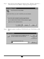
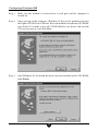
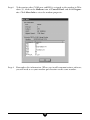
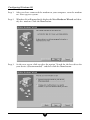
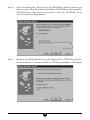
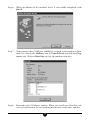
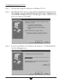
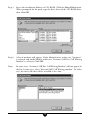
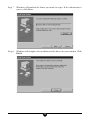
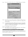
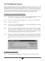
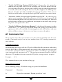
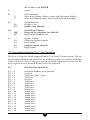
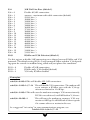
56K External
Call Waiting Modem
User Manual
Table of Contents
Introduction ........................................................................................... 3
Contacting Actiontec Customer Support ............................................ 3
Product Registration ............................................................................. 4
Safety Information ................................................................................. 4
Product Features ................................................................................... 5
Getting Started ...................................................................................... 5
Before You Begin ................................................................................... 6
Installing the Modem ............................................................................. 7
Installing the Interface Cables ........................................................... 7
Modem Controls and Indicators ........................................................... 8
Device Driver Installation and Configuration ...................................... 9
Configuring Windows 95 .................................................................... 9
Configuring Windows 95B ............................................................... 12
Configuring Windows 98 .................................................................. 15
Configuring Windows NT 4.0 ........................................................... 18
Windows 3.1X, OS/2 WARP, DOS, UnixWare, and Linux ................ 21
Installing Communications Software ................................................. 22
The Call Waiting Feature ..................................................................... 24
Using The Call Waiting Control Utility ................................................ 25
AT Command Set ................................................................................. 26
Basic AT Commands ....................................................................... 26
AT Commands Affecting ITU-T V.90 Operation ............................... 27
Examples ........................................................................................ 28
Help and Service Information ............................................................. 29
Notices ................................................................................................. 31
Proprietary Notice and Disclaimer
Unless otherwise noted, this document and the information herein disclosed are proprietary
to Actiontec Electronics, Inc. Any person or entity to whom this document is furnished or
who otherwise has possession thereof, by acceptance agrees that it will not be copied or
reproduced in whole or in part, nor used in any manner except to meet the purposes for
which it was delivered.
The information in this document is subject to change without notice and should not be
construed as a commitment by Actiontec. Although Actiontec will make every effort to inform users of substantive errors, Actiontec disclaims all liability for any loss or damage resulting from the use of this document or any hardware or software described herein, including
without limitation contingent, special or incidental liability.
PC is a trademark of IBM Corporation. MS-DOS, Windows 3.10, Windows 3.11, Windows 95 and Windows NT are trademarks of
Microsoft, Inc., K56Flex is a trademark of Lucent Technologies, Inc. and Rockwell International.
2
Introduction
Thank you for purchasing the Actiontec External 56K Call Waiting Modem. The
combination of features in this modem offer you unprecedented flexibility. By making the Call Waiting feature a part of this state-of-the-art 56K external modem, Actiontec provides you with an easy-to-use enhancement to your on-line and off-line
communications.
The Call Waiting feature of this modem allows you to be surfing the Web and receive
notification of an incoming call. Now you will not have to miss that call. When a call
comes in while the modem is using the line, the modem will ring, just like your
phone would have normally. You can pick up the phone to quickly screen the incoming call. This suspends your internet connection, rather than ending it. You can then
either stay on the phone talking or hang up to get back to surfing the Web. (Requires
that Call Waiting Service is available in your area and purchased by you from your
phone company.)
The innovative Actiontec External 56K Call Waiting Modem is also controller based.
This means full compatibility with all common PC Operating Systems such as DOS,
OS/2, UNIX, Linux, and all versions of Windows. This level of compatibility paired
with the Call Waiting feature makes the Actiontec External Call Waiting Modem a
highly versatile personal communications tool.
Contacting Actiontec Customer Support
Actiontec Electronics prides itself on making high-quality, durable, high-performance
products. If you should need assistance, the Actiontec Technical Support Department
is available from 7:00 AM to 7:00 PM Pacific Coast Time, Monday through Friday
to provide professional support.
New drivers and firmware are released as need arises to insure maximum compatibility and operation of your new External 56K Call Waiting Modem. Find out about
these and other new Actiontec products on the web at: http://www.actiontec.com.
Actiontec Electronics, Inc.
Technical Support
760 N. Mary Avenue
Sunnyvale, CA 94086
Phone: 408-752-7714 (Choose Option 7)
Fax: 408-732-0097
BBS: 408-732-0112
Email:[email protected]
3
Product Registration
The installation CD that came with your ActionLink Home Networking USB Cable
Single-Room Starter Kit contains a folder called Register. Inside this folder is a file
called “register.htm”. After installing the modem and its drivers, double-click on this
file. This will start up your browser and take you to the Actiontec web site:
http://www.actiontec.com/registration
Please fill in the required fields so that you can get prompt support and notification
of periodic product upgrades.
Safety Information
This modem is for use only with Personal Computers that have installation instructions detailing user installation of this type of peripheral device.
CAUTION:
To avoid shock hazard:
The power cord and any other equipment to which this product will be attached
must be connected to properly wired receptacles. Do not connect or disconnect any
cables or perform installation, maintenance, or reconfiguration of this product during an electrical storm.
When using your telephone equipment basic safety precautions should always be
followed to reduce the risk of fire, electrical shock, and injury. Never install telephone jacks in wet locations unless the jack is specifically designed for wet locations.
Never touch uninsulated telephone wires or terminals unless the telephone line has
been disconnected at the network interface. Use caution when installing or modifying telephone lines. Avoid using a telephone (other than a cordless type) during an
electrical storm. There may be a remote risk of electrical shock from lightning. Do
not use the telephone to report a gas leak in the vicinity of the leak.
Do not connect your modem to a digital PBX (switchboard) system, because you
may damage the modem. Modems are designed to function with analog telephone
lines, such as residential lines. Do not connect your modem to an ISDN line. In
some areas, ISDN (digital) lines are being provided for residences and businesses.
These lines may damage the modem. Please note that this modem is fully compatible
with analog telephone lines that are connected to a Digital Exchange. Digital Exchanges are used in some areas to supply analog lines to homes and businesses.
4
Product Features
This 56K* PnP (Plug-N-Play)† External Call Waiting Modem allows your computer
to connect to an ISP supporting V.90 or K56Flex™ protocols (depending on your
model). This manual describes the hardware and software installation procedures for
your new 56K or external modem.
•
Conforms to the ITU-T V.90 specification with auto-negotiation of V.90, V.34,
V.32bis, V.32, V.23, V.22bis, V.22, V.21, Bell 212A, and Bell 103 protocols.
•
Supports Group 3: class 1 fax protocols.
•
V.42bis and MNP 5 data compression. MNP2 - MNP4, V.42, and LAPM error
correction.
•
Completely controller-based PCI modem for the widest range of supported
operating systems: DOS, Windows (3.1x, 95, 98, and NT), OS/2, UNIX, Linux
•
Full-duplex
•
Call Waiting
*The External 56K Call Waiting Modem is capable of 56K downloads. However, due to FCC rules which restrict the power output of
your ISP’s modems, current download speeds are limited to 53K bps. Depending on the conditions of your telephone lines, full 53K bps
connections may not be achieved. In these cases, you will achieve speeds up to 53K bps.
† “Plug-N-Play” installation is dependant upon your operating system and computer hardware. Some systems do not support Plug-NPlay.
Getting Started
This package contains:
•
External 56K Call Waiting Modem
•
User’s Manual
•
Voice/Fax Data Communications Software
•
serial cable
•
telephone cable
•
power adapter
•
A Bonus Software CD
5
Before You Begin
Using the Telephone Answering Machine Functions with Windows 95
In order for the voice functions of the modem to work properly under 32-bit Telephony API (TAPI) applications, you need to install the Unimodem V components
for Windows 95. This file needs to be copied and installed for earlier versions of
Windows 95. To find the Windows 95 version of your system, right-click the My
Computer icon on the windows desktop and chose Properties from the menu that
appears. A dialog box will appear displaying the version information for your installation of WIndows. Follow either 1 or 2 below.
1. If you have version 4.00.950 B
This is Windows 95 OEM Service Release 2, hereafter referred to as Windows
95B. You do not need to install the Unimodem V components as they are
already built into this version of windows. Proceed to “Installing the Modem.”
2. If you have version 4.00.950 or 4.00.950 A
The Unimodem V driver needs to be installed into Windows 95. Follow the
instructions below.
Step 1
Insert the modem’s CD into the CD-ROM drive. Double click on the ‘My
Computer’ icon, then again on the CD-ROM icon.
Step 2
In the window that appears, double-click on the Unimodem folder.
Step 2
From the new folder, find the icon for the UNIMODV.INF file and click
once to highlight it. Click the icon for the right mouse button. Choose
Install from the menu that appears. This will install the Unimodem drivers.
Step 3
Restart your computer. After Windows restarts with the drivers enabled,
you may proceed to “Installing the Modem.”
6
Installing the Modem
Installing the Interface Cables
The drawing below shows the back panel of the 56K External Call Waiting Modem
and the correct cable installation. The computer interface cable has both 9-pin and
25-pin serial port connectors for use on most computers See your computer owners
manual for the location and function of your serial (COM) ports.
Note:
Connect only one connector (either 9 pin or 25 pin as appropriate) to your
computers serial (COM) port. Do not connect both.
Figure 1: Connecting the Cables
7
Modem Controls and Indicators
The front of the modem contains the power switch and modem indicator lights.
These are shown in the drawing below:
Figure 2: Modem Indicators and Controls
The power switch is a push-on/push-off type. This switch controls the ON and OFF
state of the modem. Please note that the external power adapter shown in fig. 1 also
needs to be correctly installed for power to be applied to the modem.
The LED (light emitting diode) indicators report modem status. They are:
CS (Clear to Send)
On when CTS signal is active
RS (Request to Send)
On when RTS signal is active
CD (Carrier Detect)
On when remote carrier has been detected
OH (Off Hook)
On when the modem is off hook
RD (Receive Data)
On when the modem is receiving data
SD (Transmit Data)
On when the modem is sending data
TR (Terminal Ready)
On when DTR signal is active
MR (Modem Ready)
On when power is applied to the modem
8
Device Driver Installation and Configuration
Configuring Windows 95
Step 1
Upon start-up, Windows 95 detects the modem and displays the New Hardware Found dialog box. Select ‘Driver from disk provided by hardware
manufacturer’ then Click OK.
Step 2
Insert the modem’s installation CD-ROM. Change the drive letter that appears in the dialog box to the drive letter of your CD-ROM drive. Click
OK.
9
Step 3
After copying and installing the modem’s drivers, Windows will detect a
“Wave Device for Voice Modem”, displaying the dialog box below.
Step 4
With the modem’s installation CD-ROM still in the CD-ROM drive, click
OK.
10
Step 5
Windows will complete the installation process. To check whether your
modem was installed correctly, as well as determine what COM port and
IRQ are assigned to the modem in Windows 95, click on the Modems icon
in Control Panel and click Diagnostics. Click on the COM Port icon to
select it then click More Info to view the modem properties.
Step 4
Remember this COM port number. When you install your Data/Fax software, you will need to set your modem port location to this same number.
11
Configuring Windows 95B
Step 1
Make sure the modem is connected to a serial port and the computer is
turned on.
Step 2
After starting up the computer, Windows 95 detects the modem and starts
the Update Device Driver Wizard. Insert the modem’s installation CD-ROM,
wait about 10 seconds so that the CD-ROM drive can detect and read the
CD you just put in, and click Next.
Step 3
After Windows 95 has found the drivers for your modem on the CD-ROM,
click Finish.
12
Step 4
After copying and installing the modem’s drivers, Windows will detect a
“Wave Device for Voice Modem”, displaying the dialog box below.
Step 5
After Windows 95 has found the drivers for your modem on the CD-ROM,
click Finish.
13
Step 6
To determine what COM port and IRQ is assigned to the modem in Windows 95, click on the Modems icon in Control Panel and click Diagnostics. Click More Info to view the modem properties.
Step 4
Remember this information. When you install communications software,
you will need to set your modem port location to this same number.
14
Configuring Windows 98
Step 1
After you have connected the modem to your computer, turn the modem
on. Start up your system.
Step 2
Windows 98 will immediately display the New Hardware Wizard and identify the modem. Click the Next button.
Step 3
At the next screen, click to select the option “Search for the best driver for
your device. (Recommended)” and then click the Next button.
15
Step 4
At the next dialog box, click to select CD-ROM drive. Before advancing to
the next screen, insert the modem’s installation CD-ROM into the computer’s
CD-ROM drive. Wait about ten seconds, so that the CD-ROM can be
read, then click the Next button.
Step 5
Windows 98 will find the driver on the floppy disk or CD-ROM and identify the modem as a “Actiontec 56K Ext. Call Waiting Modem”. Click Next.
16
Step 6
When installation of the modem’s driver is successfully completed, click
Finish.
Step 7
To determine what COM port and IRQ is assigned to the modem in Windows 98, click on the Modems icon in Control Panel and click the Diagnostics tab. Click on More Info to view the modem properties.
Step 8
Remember this COM port number. When you install your Data/Fax software, you will need to set your modem port location to this same number.
17
Configuring Windows NT 4.0
Step 1
Start up your computer and log on to Windows NT 4.0.
Step 2
After Windows NT restarts, on the taskbar, click Start. On the Start menu,
click Settings, then click Control Panel and double-click the Modems icon.
An Install New Modem dialog box should appear. Allow windows NT to
detect your modem. Click Next.
Step 4
In most cases Windows NT will detect the modem as a “Standard Modem”.
Click the Change button.
18
Step 5
Insert the installation diskette or CD-ROM. Click the Have Disk button.
When prompted for the path, type the drive letter of the CD-ROM drive,
then click OK.
Step 6
A list of modems will appear. Under Manufacturer, make sure “Actiontec”
is selected, and under Models, make sure “Actiontec 56K Ext. Call Waiting
Modem” is selected. Click OK.
Note:
In some cases, “Actiontec 56K Ext. Call Waiting Modem” will not appear in
the list. In that case, select “External 56K Call Waiting modem.” In either
case, the driver file that will be installed is the same.
19
Step 7
Windows will confirm the choice you made in step 6. If the information is
correct, click Next.
Step 8
Windows will complete the installation of the drivers for your modem. Click
Finish.
20
Step 9
Your modem should be added to the list in Modems Properties. Click Close.
Step 8
If you wish to use your modem to dial into a Windows NT Remote Access
Server or wish to connect to the Internet, you will need to configure Dial
Up Networking.
Step 9
To install Dial Up Networking, Windows NT may request its own installation diskettes for some files. Insert the Windows NT disks or CD-ROM as
required. At the Remote Access Setup dialog box, click on Add. Select the
RAS Device you wish to add and click OK.
Step 10 Click Continue to finish the installation.
Step 11 After Windows NT has completed the binding process, allow Windows
NT to shut down and restart the computer.
Configuring Windows 3.1X, OS/2 WARP, DOS, UnixWare, and Linux
Since your External 56K Call Waiting Modem uses a preexisting COM port, configuration should be automatic. The communications software provided will search
for and recognize the modem for you.
21
Installing Communications Software
Note:
Some configurations are packaged without communications software. Check
your packaging to see if communications software is included.
If your modem came with a communications software package, it is strongly recommended that you use this software for your modem, rather than a different version of
the software or software from a different vendor. The default installation parameters
in the software that came with this modem have been specially configured to work
with this modem. The Users Guide for this program can be found inside the modem
package. It can be supplied in either soft-bound copy or on CD-ROM (depending
on the model you purchased).
If you wish to use another software package, please be sure that it supports this modem. Most Software Manufacturers have a listing of supported modems on their
websites or BBS’s. Check these sites to see if this model is supported. If you are
unsure or your brand of software supports only a few modems, try selecting “Hayes
Compatible” or “Standard Modem”. This may work in certain cases.
Some software programs allow manual input of parameters. For the users of these
programs, here is a listing of the Data/Fax/Voice Command Standards supported.
Data:
Fax:
Voice:
Init String:
TIA/EIA-602
TIA/EIA-578 for Class 1 Fax
TIA IS-101 support for TAD (Telephone Answering Device)
AT&F&C1&D2W2
TIA IS-101 Commands not supported:
Caller ID
Full Duplex Speakerphone
VoiceView
Note: some programs must be configured to communicate with the modem on the
same COM port and or IRQ setting used by the modem. See “Installing the Modem”
for instructions on how to determine your COM Port and IRQ settings.
The Modem’s Voice Features
This modem supports TIA IS-101 commands applicable to a Telephone Answering
Device. In order to take advantage of this feature, you will need a Sound Blaster®
compatible sound card equipped with an external microphone and external speakers.
A software application which supports these TAD functions (such as the one supplied with the modem) is also required.
22
A modem based Telephone Answering Machine works by using a sound card equipped
with a microphone to record an outgoing message. This message is stored as a .wav
file which is transferred to the modem by the application program when an incoming
call is detected. The modem’s internal electronics converts the digital information
contained in the .wav file into an audio signal which is then sent over the phone line.
The person calling hears your outgoing message and responds with an incoming
message.
The sequence of recording an incoming message is the reverse of an outgoing message. The modem converts the audio signal into a digital format and sends it to the
application program. The application program then formats and stores the incoming
message as a .wav file. When you play back your stored messages by selecting them
from within the application program, they are sent to the sound card. You then hear
your recorded messages through the sound card’s speakers.
The default parameters of the software which came with your modem have been
specially configured to identify and use your modems voice capabilities. Even if you
have decided to use another third-party application, try your included application
first. This will allow you to test the modem and its voice functions before investing in
an expensive retail software package.
23
The Call Waiting Feature
With the Call Waiting feature from your telephone company and the Actiontec’s Call
Waiting Modem installed, your modem will notify you of an incoming call as you are
surfing the Web. You may pick up the phone that is connected to your modem to
find out who is calling you, and you’ll have a period of time (approximately 7 seconds, depending on your ISP) to hang up the phone and continue surfing.
To Receive an Incoming Call while Online:
Step 1
You will hear a ring every 6 seconds. This will originate from the modem
rather than from the phone, and it will be repeated for 5 rings.
Step 2
To receive the call, pick up the phone that is connected to your modem.
Step 3
Talk to the calling party.
Step 4
If you hang up within approximately 7 seconds (depending on your ISP)
you may continue to surf the Web.
Note:
If after screening the incoming call you wish to quickly finish your online
work and continue talking to the caller, ask the caller to stay on the line.
Hang up the phone, and finish your work. After disconnecting the modem
you can pick up the phone and continue talking to the caller.
Step 5
If you want to talk to the calling party or the time period exceeds the ISP’s
time limit, your Internet access will be automatically disconnected. A Reestablish Connection box will appear for you to easily reconnect to the internet.
To Ignore an Incoming Call
Step 1
Just disregard the audible rings. It will ring 5 times and then will quit.
24
Step 2
Or, you may pick up the handset and immediately hang up.
Note: Use of the Call Waiting feature requires:
•
Actiontec’s Call Waiting Modem
•
Call Waiting Service from your telephone company
•
You are using your Call Waiting Modem.
•
You have a phone connected to the Call Waiting Modem.
•
You do not disable the Call Waiting Service from your telephone company via
the touch-tone sequence of *70.
Using The Call Waiting Control Utility
The Call Waiting Control Utility software allows you to decide how you want to
mange incoming phone calls while online. It gives you three choices. While you are
online, you can choose to have the modem ring, notifying you of an incoming phone
call. You can also choose to have the modem automatically terminate your Internet
connection upon receipt of a call. Or you can disable Call Waiting altogether.
25
•
“Enable Call Waiting Ringing (Still Online)”--If you select this option the
modem will ring when you receive an incoming call. With this option selected,
you can pick up the phone, find out who is calling, hang up within approximately
7 seconds, and resume surfing the Internet. Or you can ignore the call altogether.
You can also place the caller on hold by hanging up the phone. Then you can
finish your work online, pick up the phone again and continue your conversation.
•
“Automatic Online Disconnection Upon Receipt Of Call”-- By choosing this
option, your incoming calls will have priority over the Internet connection. All
of your household phones will ring when you receive an incoming call. Your link
to the Internet will have been terminated, and anyone in the house may pick up
the phone and speak to the caller.
•
“Disable Call Waiting Notification (Ringing)”-- the effect of this option is similar
to that of the “*70” prefix you can dial to disable call waiting. If you choose this
option you will not be notified of incoming phone calls while online, and your
callers will hear a ring, as if you were not home to answer the phone.
AT Command Set
There may be times when you need to access the modem manually with AT commands. Commands may be sent to your modem from a PC running communications software.
Command Format
All commands must begin with the AT prefix, followed by the parameter and ending
with the ENTER key. All commands may be typed in either upper or lower case, but
not mixed A command without any parameters will be considered as specifying the
same command with a parameter of “0”. The maximum command length is eight (8)
characters. The modem does not count the AT prefix, carriage returns, or spaces.
Example:
ATH
This command causes your modem to hang up.
Basic AT Commands
In the following listings, all default settings are printed in bold text.
Command
Function
A/
Repeat last command. Do not precede A/ with
26
AT or follow with ENTER
A
Answer
D_
P
T
Dial command
Select pulse dialing; affects current and subsequent dialing
Select tone dialing; affects current and subsequent dialing
E0
E1
Command echo
Disables echo
Enables echo (default)
H0
H1
Switch hook Control
Hangs up the telephone line (default)
Picks up the telephone line
L0
L1
L2
L3
Speaker volume
Off or low speaker volume
Low volume
Medium volume (default)
High volume
En
Hn
Ln
AT Commands Affecting ITU-T V.90 Operation
There are 3 S-registers which support K56flex, V.90, and V.34 connections. S38 sets
the maximum downstream speed that the modem attempts to connect. To disable
V.90, set S38 to 0. The S37 register is used to control the upstream V.34 rate. Use the
S109 register to select between K56flex and V.90 protocols.
S37
Dial Line Rate (default 0)
S37 = 0
S37 = 1
S37 = 2
S37 = 3
S37 = 4
S37 = 5
S37 = 6
S37 = 7
S37 = 8
S37 = 9
S37 = 10
S37 = 11
S37 = 12
S37 = 13
S37 = 14
S37 = 15
S37 = 16
S37 = 17
S37 = 18
S37 = 19
maximum modem speed (default)
reserved
1200 bits/s and 75 bits/s
300 bits/s
reserved
1200 bits/s
2400 bits/s
4800 bits/s
7200 bits/s
9600 bits/s
12000 bits/s
14400 bits/s
16800 bits/s
19200 bits/s
21600 bits/s
24000 bits/s
26400 bits/s
28800 bits/s
31200 bits/s
33600 bits/s
27
S38
56K Dial Line Rate (default 1)
S38 = 0
S38 = 1
S38 = 2
S38 = 3
S38 = 4
S38 = 5
S38 = 6
S38 = 7
S38 = 8
S38 = 9
S38 = 10
S38 = 12
S38 = 13
S38 = 14
S38 = 15
S38 = 16
S38 = 17
S38 = 18
S38 = 19
S38 = 20
Disable all 56K connections
autorate - maximum achievable connection (default)
29333 bits / s
30666 bits / s
32000 bits / s
33333 bits / s
34666 bits / s
36000 bits / s
37333 bits / s
38666 bits / s
40000 bits / s
42666 bits / s
44000 bits / s
45333 bits / s
46666 bits / s
48000 bits / s
49333 bits / s
50666 bits / s
52000 bits / s
53333 bits / s
S109
K56flex and V.90 Selection (default 1)
Use this register to disable 56K connections or to choose between K56flex and V.90
protocols. The default setting (S109=1) will attempt K56flex and then V.34 depending upon the central site modem being called and your phone line conditions.
S109 = 0
S109 = 1
S109 = 2
Disable all 56K connections
K56flex only, V.90 disabled (default)
V.90 only. K56flex disabled
Examples
at&fs38=0s109=0This will disable ALL 56K connections
at&fs38=1s109=1s37=14 This will disable V.90 connections. The modem will
try to connect at K56flex rates with the V.34 upstream rate limited to 21.6K bps.
at&fs38=1s109=2This will cause the modem to attempt a V.90 connection only.
If V.90 is not achieved, it will fall back to V.34 rates.
at&fs38=10s109=2
This will cause the modem to attempt a V.90 connection at 40K bps. It will fall back to slower speeds
if it cannot achieve or maintain this rate.
As a suggested “init string” in your communications program, use:
at&fw2s109=2s38=1s37=14
28
Help and Service Information
General Troubleshooting Tips
This section presents solutions to some common problems you may experience when
installing your modem. Some solutions may not apply to your operating system or
environment. If you cannot resolve your difficulty, contact your dealer or vendor for
assistance.
Modem Does Not Respond To Commands
•
Verify that the modem is turned on.
•
Make sure the modem is installed into a serial (COM) port connector. Consult
your computer user’s manual for the location and function of your installed
serial ports.
•
Make sure the modem is initialized correctly. Issuing AT&F and pressing ENTER
(see “AT Commands”) will reset the modem to its factory default settings.
•
Make sure the baud rate setting in the communications software is set to the
correct value. An incorrect baud rate prevents the modem from operating properly.
Modem Does Not Dial
•
Make sure the modem is turned on, and connected to a working phone line.
Replace the modem with a telephone to ensure that the line is working.
Modem Dials But Does Not Connect
•
Make sure the communications software is configured to the same COM Port
and IRQ setting as the modem.
•
Be sure the phone line is working properly. Replace the modem with a regular
phone and dial the number. If the line sounds noisy, you may have difficulty
connecting to the remote device.
Modem Experiences Errors Or Disconnects
•
Make sure the phone line does not exhibit excess noise.
•
Make sure RTS/CTS hardware flow control is enabled and XON/XOFF software
flow control is disabled in the communications software.
29
Reconfiguring a Windows Dial-Up Networking Connection
When you attempt to check your modem windows may issue a “COM port open”
error message. This means there are some previously installed modem configurations
using the same COM Port as the Actiontec 56K External Call Waiting Modem and
are interfering with it’s operation. These are most likely old Dial-Up Networking
connections. This problem is easily corrected by following these simple steps.
Step 1
Double-click the My Computer icon located on the Windows Desktop
screen.
Step 2
In My Computer, double-click the Dial-Up Networking folder icon. Find
the dial-up profile for any old modem(s). Right-click on the icon to bring
up the menu.
Step 3
Choose Properties from the menu that appears. In the Connect using box,
select your new modem and then click the OK button. This will reconfigure the dial-up profile to point to the new modem.
Note:
Be sure to perform this procedure on all Dial-Up connections present. After you have clicked the OK button in the Properties screen, you should
restart the computer. This should clear the “Open COM port” error.
30
Notices
Declaration of Conformity
This equipment has been tested and found to comply with the limits for a Class B
digital device, pursuant to Part 15 of the FCC Rules. These limits are designed to
provide reasonable protection against harmful interference in a residential installation. This equipment generates, uses and can radiate radio frequency energy and, if
not installed and used in accordance with the instructions, may cause harmful interference to radio communications. However, there is no guarantee that interference
will not occur in a particular installation. If this equipment does cause harmful interference to radio and television reception, the user is encouraged to try to correct the
interference by one or more of the following measures:
• Reorient the receiving antenna.
• Increase the separation between the equipment and receiver.
• Connect the equipment into an outlet on a circuit different from that to which the
receiver is connected.
• Consult the dealer or an experienced radio/TV technician for help.
CAUTION: CHANGES OR MODIFICATIONS NOT EXPRESSLY
APPROVED BY THE PARTY RESPONSIBLE FOR COMPLIANCE
COULD VOID THE USER’S AUTHORITY TO OPERATE THE
EQUIPMENT.
Telecommunications Regulations
The following three statements are provided in accordance with the Federal Communications Commission (FCC) and CDOC (Canada) regulations. Please read these
statements carefully before installing your modem.
FCC PART 68 REQUIREMENTS
This equipment complies with Part 68 of the FCC Rules. On the bottom of this
equipment is a label that contains, among other information, the FCC Registration
Number and Ringer Equivalence Number (REN) for this equipment. If requested,
this information must be given to the telephone company.
The REN is used to determine the maximum number of devices connected to your
telephone line that will ring in response to an incoming call. In most, but not all,
31
areas, the total REN of devices connected to a line should not exceed five (5.0). To
find out the total permitted in your area, contact your local telephone company.
If your telephone equipment causes harm to the telephone network, the telephone
company can discontinue your service temporarily. If possible, the company will
notify you in advance. But if advance notice isn’t practical, you will be notified as
soon as possible. You will be informed of your right to file a complaint with the FCC.
Your telephone company can make changes in its facilities, equipment, operations,
or procedures that could affect the operation of your equipment. If so, you will be
notified in advance so you can make the changes needed to maintain uninterrupted
service.
If you experience trouble with this equipment, please contact the manufacturer at the
address given in this manual. The telephone company may ask that you disconnect
this equipment from the network until the problem has been corrected or until you
are sure that the equipment in is not malfunctioning.
Canadian Department Of Communications (CDOC) Certification Label
NOTICE: The Canadian Department of Communications label identifies certified
equipment. This certification means that the equipment meets certain telecommunications network protective, operational, and safety requirements. The Department does
not guarantee the equipment will operate to the user’s satisfaction.
Before installing this equipment, users should ensure that it is permissible to be connected to the facilities of the local telecommunications company. The equip ment must
also be installed using an acceptable method of connection. In some cases, the
company’s inside wiring associated with a single line individual service may be extended by means of a certified connector assembly (telephone extension cord). The
customer should be aware that compliance with the above conditions may not prevent degradation of service in some situations.
Repairs to certified equipment should be made by an authorized Canadian maintenance facility designated by the supplier. Any repairs or alterations made by the user
to this equipment, or equipment malfunctions, may give the telecommunications
company cause to request the user to disconnect the equipment.
Users should ensure for their own protection that the electrical ground connections
of the power utility, telephone lines, and internal metallic water pipe system, if present,
are connected together. This precaution may be particularly important in rural areas.
CAUTION: Users should not attempt to make such connections themselves, but
should contact the appropriate electric inspection authority, or electrician, as appropriate.
32
33