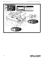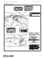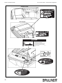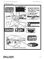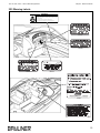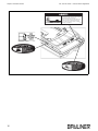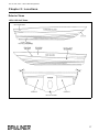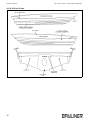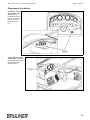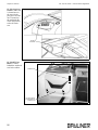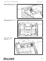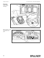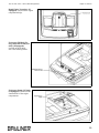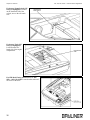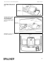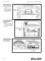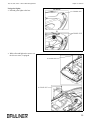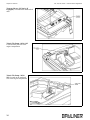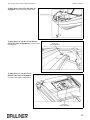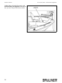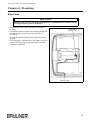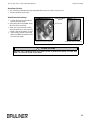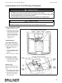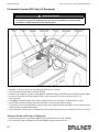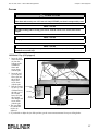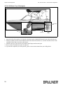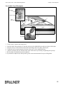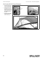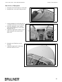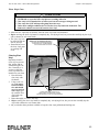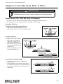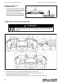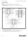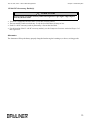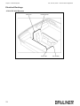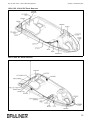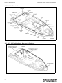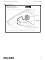
1
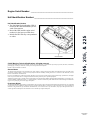
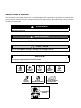
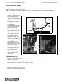
Engine Serial Number: _____________________________________
Hull Identification Number:__________________________________
Hull Identification Number
• The Hull Identification Number (HIN) is
located on the starboard hullside just forward of the transom.
• Record the HIN (and the engine serial
numbers) in the space provided above.
• Include the HIN with any correspondence
or orders.
© 2007 Bayliner Technical Publications. All rights reserved.
No part of this publication may be reproduced, stored in any retrieval system, or transmitted in any form by any means, electronic, mechanical,
photocopying, recording or otherwise, without prior written permission of Bayliner.
Printed in the United States of America.
General Notes
The material in this document is for information only and is subject to change without notice. While reasonable efforts have been made in the
preparation of this document to assure its accuracy, Bayliner assumes no liability resulting from errors or omissions in this document, or from
the use of information contained herein.
Due to our commitment to product improvement, Bayliner reserves the right to make changes in the product design, specifications, and equipment at any time without notice or obligation. Illustrations and/or photos may show optional equipment.
All Bayliner products meet or exceed USCG (United States Coast Guard) and/or NMMA (National Marine Manufacturer’s Association) construction standards. Manufactured with 1,1,1 Trichloroethane, a substance which harms public health and environment during the manufacturing process by destroying ozone in the upper atmosphere.
Proprietary Rights
This document discloses subject matter in which Bayliner has proprietary rights. The information and design disclosed herein were originated
by and are the property of Bayliner. Neither receipt nor possession thereof confers or transfers any right to reproduce, copy, alter or disclose the
document or any part thereof, any information contained therein, or to construct boats or any item from it, except by written permission from or
written agreement with Bayliner. This document is to be returned upon request to Bayliner.
Part Number
1911152
CONTENTS
Chapter 1: Welcome Aboard!
Chapter 3: Propulsion & Related Systems
185 Dimensions & Tank Capacities 1
Engine 37
195 Dimensions & Tank Capacities 1
Bilge Blower System 38
205 Dimensions & Tank Capacities 1
Fuel System 39
225 Dimensions & Tank Capacities 1
Fuel Fill & Vent 41
Fuel Filters 41
Anti-siphon Valve (Gas Engine Only) 41
Fuel Filter/Water Separator (Diesel Engine Only) 42
Dealer Service 2
Warranty Information 2
Boating Experience 2
Quick Oil Drain System 43
Engine & Accessory Guidelines & Literature 3
Propeller 3
Chapter 4: Controls & Gauges
Structural Limitations 4
Steering 44
Qualified Maintenance 4
Shift/Throttle Control 44
Special Care for Moored Boats 4
Power Trim & Tilt 44
Safety Standards 5
Gauges 45
Carbon Monoxide (CO) 6
Cleaning the Gauges 45
Gauge Fogging 45
Radio Transmission Interference 45
Fuel Gauge 45
CO Facts 6
Factors that Increase the Effects of CO Poisoning 6
Where & How CO Can Accumulate 7
How to Protect Yourself & Others From CO 7
CO Checklists 8
More Information 8
Chapter 5: Navigation Equipment
Depth Finder (If Equipped) 46
185 Warning Labels 9
195 Warning Labels 11
205 Warning Labels 13
Chapter 6: Plumbing
Bilge Pump 47
225 Warning Labels 15
Bilge Pump Testing 48
Autofloat Switch 49
Chapter 2: Locations
Seawater Systems 50
Exterior Views 17
185 & 195 Hull Views 17
205 & 225 Hull Views 18
185 Deck Views 19
195 Deck Views 20
205 Deck Views 21
225 Deck View 22
185, 195 & 225 Helm 23
205 Helm 24
Component Locations 25
Seacocks 50
Seawater Strainers 50
Livewell System (185, 195 & 205 Only) (If Equipped) 51
Freshwater System (225 Only) (If Equipped) 52
Transom Shower (225 Only) (If Equipped) 52
Freshwater System Winterization 53
Drain Systems 53
Deck Drains 53
Chapter 7: Deck Equipment
Chapter 10: Lights
Cleats & Bow/Stern Eyes 54
Care & Maintenance 70
Bow Mount Trolling Motor (185, 195 & 205 Only)
(If Equipped) 54
Interior & Exterior Lights 70
Navigation Lights 70
Ski-Tow Ring 54
Ski-Tow Tower (If Equipped) 55
Chapter 11: Electrical System
Attaching the Ski-tow Rope 55
Folding the Ski-tow Tower (If Equipped) 56
12-Volt DC System 72
Canvas 57
185 Bimini Top (If Equipped) 57
205 & 225 Bimini Top (If Equipped) 58
Convertible Top (If Equipped) 59
Side Curtains (205 & 225 Only) (If Equipped) 60
Bow Cover (If Equipped) 61
Canvas Care 62
Clear Vinyl Care 63
Chapter 8: Entertainment Systems
Battery 72
Fuses 72
12-Volt DC Accessory Outlet(s) 73
Alternator 73
Electrical Routings 74
12-Volt DC Hull Harness 74
185 & 195 12-Volt DC Deck Harness 75
205 12-Volt DC Deck Harness 75
225 12-Volt DC Deck Harness 76
185, 195 & 205 Trolling Motor Harness (If Equipped) 76
Battery Cable Routings 77
Audio Equipment 64
Chapter 9: Convertible Seats, Beds, & Tables
Sleeper Seats (185, 195 & 205 Only) (If Equipped) 65
Operating Positions 65
Lounge Positions 65
Jump Seat to Sunlounge Conversion 66
Passenger Seat to Sunlounge Conversion
(225 Only) 67
Installing & Removing Table Leg (225 Only) 68
Removable Fishing Seats (185, 195 & 205 Only)
(If Equipped) 69
Important Records 78
Float Plan 79
Hazard Boxes & Symbols
The hazard boxes and symbols shown below are used throughout this supplement to call attention to potentially dangerous situations which could lead to either personal injury or product damage. Read all warnings carefully and follow all safety instructions.
!
DANGER!
This box alerts you to immediate hazards which WILL cause severe personal injury or death if
the warning is ignored.
WARNING!
!
This box alerts you to hazards or unsafe practices which COULD result in severe personal
injury or death if the warning is ignored.
!
CAUTION
This box alerts you to hazards or unsafe practices which COULD result in minor personal
injury or cause product or property damage if the warning is ignored.
NOTICE
This box calls attention to installation, operation or maintenance information, which is important to proper operation but is not hazard related.
FIRE
HAZARD!
EXPLOSION
HAZARD!
FALLING
HAZARD!
NO OPEN
FLAME!
ROTATING
PROPELLER HAZARD!
ELECTRICAL
HAZARD!
HOT
HAZARD!
RUN BILGE BLOWERS
FOR 4 MINUTES!
CO POISONING
HAZARD!
185, 195, 205, & 225 • Owner’s Manual Supplement
Chapter 1: Welcome Aboard!
• This Owner’s Manual Supplement provides specific information about your boat that is not covered in the Sport
Boat Owner’s Manual.
• The Sport Boat Owner’s Manual contains general information about safe operating practices, general boating regulations, and general maintenance techniques. Information that is more specific to your particular boat is found in
this Owner’s Manual Supplement.
• Before using your boat, study this Owner’s Manual Supplement, the Sport Boat Owner’s Manual, and all engine
and accessory literature carefully. If similar instructions are found in more than one manual, always refer to the
specific manufacturer’s manual (such as the engine manual) for the most complete and accurate information.
• Keep this Owner’s Manual Supplement and the Sport Boat Owner’s Manual on your boat in a secure, yet readily
available place.
185 Dimensions & Tank Capacities
Overall
Length
Length
Rigged
Bridge
Clearance
Beam
Draft
(Hull)
Draft
(Maximum)
Fuel
Tank
18' 0"
19' 1"
6' 0"
7' 7"
1' 8"
3' 0"
28 Gallons
195 Dimensions & Tank Capacities
Overall
Length
Length
Rigged
Bridge
Clearance
Beam
Draft
(Hull)
Draft
(Maximum)
Fuel
Tank
19' 0"
21' 0"
7' 1"
7' 11"
1' 10"
3' 3"
35 Gallons
205 Dimensions & Tank Capacities
Overall
Length
Length
Rigged
Bridge
Clearance
Beam
Draft
(Hull)
Draft
(Maximum)
Fuel
Tank
20' 5"
21' 2"
7' 1"
8' 2"
1' 8"
3' 1"
37 Gallons
225 Dimensions & Tank Capacities
Overall
Length
Length
Rigged
Bridge
Clearance
Beam
Draft
(Hull)
Draft
(Maximum)
Fuel
Tank
Freshwater
Tank
22' 1"
23' 11"
7' 4"
8' 6"
1' 6"
2' 9"
50 Gallons
10 Gallons
1
185, 195, 205, & 225 • Owner’s Manual Supplement
Chapter 1: Welcome Aboard!
Dealer Service
•
•
•
•
•
•
Your dealer is your key to service.
Ask your dealer to explain all systems before taking delivery of your boat.
Contact your dealer if you have any problems with your new boat.
If your dealer cannot help, call our customer service hotline: 360-435-8957 or send us a FAX: 360-403-4235.
Buy replacement parts from any authorized Bayliner dealer.
You can access on-line parts catalogs, links to vendor websites, and other helpful features by logging on
to http://www.baylinercustomercare.com.
Warranty Information
• Bayliner offers a Limited Warranty on each new Bayliner purchased through an authorized Bayliner dealer.
• A copy of the Limited Warranty was included in your owner’s packet.
• If you did not get a copy of the Limited Warranty, please contact your Bayliner dealer or call 360-435-8957 for
a copy.
Boating Experience
!
WARNING!
CONTROL HAZARD!
An experienced operator MUST be in control of your boat at ALL times. Do NOT operate your
boat while under the influence of alcohol or drugs.
If this is your first boat or if you are changing to a type of boat you are not familiar with, for your own comfort and
safety, get handling and operating experience before assuming command of your boat.
Take one of the boating safety classes offered by the U.S. Power Squadrons or the U.S. Coast Guard Auxiliary. For
more course information, including dates and locations of upcoming classes, contact the organizations directly:
• U.S. Power Squadrons: 1-888-FOR-USPS (1-888-367-8777) or on the Internet at: http://www.usps.org
• In Canada, for the CPS courses call 1-888-CPS-BOAT.
• U.S. Coast Guard Auxiliary: 1-800-368-5647 or on the Internet at: http://www.cgaux.org
Outside the United States, your selling dealer, national sailing federation, or local boat club can advise you of local
sea schools or competent instructors.
2
185, 195, 205, & 225 • Owner’s Manual Supplement
Chapter 1: Welcome Aboard!
Engine & Accessory Guidelines & Literature
NOTICE
BEFORE starting or working on your engine(s), read the engine manual.
NOTICE
BEFORE using the accessories on your boat, read the accessory manuals.
NOTICE
BEFORE storing your boat, refer to your engine and accessory manuals for storage/winterization instructions.
NOTICE
Certain modifications to your boat WILL result in cancellation of your warranty protection.
ALWAYS check with your dealer BEFORE making any modifications to your boat.
• Your boat’s engine and accessories were selected to provide optimum performance and service.
• Installing a different engine or adding accessories may affect your boat’s running trim.
• If you choose to install a different engine or add accessories that may affect your boat’s running trim, have a
trained marine technician perform a safety inspection and handling test before using your boat again.
• The engine and accessories on your boat have their own manuals. Read these manuals before using the engines
and accessories.
Unless noted otherwise, all engine and accessory literature referred to in this supplement is included in your owner’s
packet.
While the topics listed below may be included in this supplement and in the Sport Boat Owner’s Manual, always
refer to the engine manual first for specific information on these important subjects:
• Engine Break-in Procedure
• Fuel and Oil Recommendations
• Engine Starting and Stopping
• Engine Maintenance
• Gear Shifting
• Engine Storage/Winterization
Propeller
!
CAUTION
ENGINE DAMAGE HAZARD!
The factory standard propeller may not be the best for your particular boat and load conditions. Refer to the engine manual for engine RPM ratings. The engine should reach, but not
exceed its full rated RPM when full-throttle is applied.
Immediately contact your local Bayliner dealer if:
• The engine cannot reach its full rated RPM when full-throttle is applied, or;
• The engine exceeds its full rated RPM when full-throttle is applied.
• Keep the propeller in good repair and at the correct pitch for your particular situation.
• A slightly bent or nicked propeller will adversely affect the performance of your boat.
3
185, 195, 205, & 225 • Owner’s Manual Supplement
Chapter 1: Welcome Aboard!
Structural Limitations
The transom platform extension is designed to be lightweight for proper boat balance. The load limit for the transom
platform extension is 30 pounds per square foot, evenly distributed.
Qualified Maintenance
!
WARNING!
To maintain the safety of your boat, allow ONLY trained personnel to work on, or change, in
any way, the:
• Steering system
• Propulsion system
• Engine control system
• Fuel system
• Environmental control system
• Electrical system
• Navigation system
Failure to maintain your boat’s systems (listed in the warning above) as designed could violate the laws in your jurisdiction and could expose yourself and others to the danger of bodily injury or accidental death.
Follow the maintenance instructions in:
• this Owner’s Manual Supplement
• the Sport Boat Owner’s Manual
• the engine owner’s manual, and;
• all accessory literature.
Special Care for Moored Boats
NOTICE
• To help seal the hull bottom and reduce the chance of gel coat blistering while your boat is
moored, apply an epoxy barrier coating.
• The barrier coating should be covered with several coats of anti-fouling paint.
• Many states regulate the chemical content of bottom paints in order to meet environmental
standards. Check with your local dealer about recommended bottom paints, and about the
laws in effect in your area.
• Whether moored in saltwater or freshwater, your boat will collect marine growth on its hull bottom.
• This will detract from your boat’s beauty, greatly affect its performance, and may damage the gel coat.
• Periodically haul your boat out of the water and scrub the hull bottom with a bristle brush and a solution of soap
and water.
4
185, 195, 205, & 225 • Owner’s Manual Supplement
Chapter 1: Welcome Aboard!
Safety Standards
!
DANGER!
FALLING and ROTATING PROPELLER HAZARD!
• NEVER allow anyone to ride on parts of your boat NOT designed for
such use.
• Sitting on seat-backs, lounging on the forward deck, bow riding, gunwale riding or occupying the transom platform while underway is especially hazardous and
WILL cause personal injury or death.
!
DANGER!
FALLING, ROTATING PROPELLER and CARBON
MONOXIDE POISONING HAZARD!
• NEVER allow anyone to occupy, or hang from, the
back deck or transom platform while the engine
is running.
• Teak surfing, dragging, or water skiing within 20 feet
of a moving watercraft can be fatal.
!
DANGER!
DANGER
PERSONAL SAFETY HAZARD!
• ALWAYS secure the anchor and other loose objects BEFORE getting underway.
• The anchor and other items that are NOT properly secured can come loose when your boat
is moving and cause personal injury or death.
!
WARNING!
A wide variety of components used on this vessel contain or emit chemicals known to the State
of California to cause cancer and birth defects and other reproductive harm.
Examples Include:
• Engine and generator exhaust
• Engine and generator fuel, and other liquids such as coolants and oil, especially used
motor oil
• Cooking fuels
• Cleaners, paints, and substances used for vessel repair
• Waste materials that result from wear of vessel components
• Lead from battery terminals and from other sources such as ballast or fishing sinkers
To Avoid Harm:
• Keep away from engine, generator, and cooking fuel exhaust fumes.
• Wash exposed skin thoroughly with soap and water after handling the substances above.
• Your boat’s mechanical and electrical systems were designed to meet safety standards in effect at the time it
was built.
• Some of these standards were mandated by law, and all of them were designed to insure your safety and the safety
of other people, vessels and property.
Read this supplement, the Sport Boat Owner’s Manual, the engine owner’s manual, and all accessory instructions for
important safety standards and hazard information.
5
185, 195, 205, & 225 • Owner’s Manual Supplement
Chapter 1: Welcome Aboard!
Carbon Monoxide (CO)
!
DANGER!
• Carbon monoxide gas (CO) is colorless, odorless, tasteless, and
extremely dangerous.
• ALL engines, generators, and fuel burning appliances produce CO
as exhaust.
• Prolonged exposure to low concentrations or very quick exposure to high
concentrations WILL cause BRAIN DAMAGE or DEATH.
• Teak surfing, dragging, or water skiing within 20 feet of a moving watercraft can be fatal.
CO Facts
• CO poisoning causes a significant number of boating deaths each year.
• Called the "silent killer", CO is an extremely toxic, colorless, odorless and tasteless gas.
• CO can harm or even kill you inside or outside your boat.
• CO can affect you whether you’re underway, moored, or anchored.
• CO symptoms are similar to seasickness or alcohol intoxication.
• CO can make you sick in seconds. In high enough concentrations, even a few breaths can be fatal.
• Breathing CO blocks the ability of your blood to carry oxygen.
• The effects are cumulative. Even low levels of exposure can result in injury or death.
Factors that Increase the Effects of CO Poisoning
• Age
• Smokers or people exposed to high concentrations of cigarette smoke
• Consumption of alcohol
• Lung disorders
• Heart problems
• Pregnancy
6
185, 195, 205, & 225 • Owner’s Manual Supplement
Chapter 1: Welcome Aboard!
Where & How CO Can Accumulate
Stationary conditions that increase CO accumulations include:
A. Using engine, generator, or other fuel burning device when boat is moored in a confined space.
B. Mooring too close to another boat that is
using its engine, generator, or other fuel
burning device.
To correct stationary situations A and/or B:
• Close all windows, portlights and hatches.
• If possible, move your boat away from source of CO.
Running conditions that increase CO accumulations include:
C. Running boat with trim angle of bow too high.
D. Running boat without through ventilation
(station wagon effect).
To correct running situations C and/or D:
• Trim bow down.
• Open windows and canvas.
• When possible, run boat so that prevailing winds help dissipate exhaust.
How to Protect Yourself & Others From CO
• Know where and how CO may accumulate in and around your boat (see above).
• Always maintain fresh air circulation throughout your boat.
• Know where your engine and generator exhaust outlets are located and keep everyone away from these areas.
• Never sit on, or hang onto, the back deck or transom platform while the engine is running.
• Never enter the areas under transom platforms where exhaust outlets are located.
• Although CO can be present without the smell of exhaust fumes, if exhaust fumes are detected on your boat, take
immediate action to dissipate these fumes.
• Treat symptoms of seasickness as possible CO poisoning. Get the person into fresh air immediately. Seek medical
attention—unless you’re sure it’s not CO.
• Install and maintain CO monitors inside your boat. Never ignore any alarm. Replace monitors as recommended by the monitor manufacturer.
• Follow the checklists provided on the next page.
• Get a Vessel Safety Check.
For information on how to get a free VESSEL SAFETY CHECK, visit www.vesselsafetycheck.org or contact your
local U.S. Coast Guard Auxiliary or United States Power Squadrons®.
• U.S. Coast Guard Auxiliary: 1-800-368-5647 or on the Internet at: http://www.cgaux.org
• U.S. Power Squadrons: 1-888-FOR-USPS (1-888-367-8777) or on the Internet at: http://www.usps.org
7
185, 195, 205, & 225 • Owner’s Manual Supplement
Chapter 1: Welcome Aboard!
CO Checklists
Trip Checklist
❏ Make sure you know where the exhaust outlets are located on your boat.
❏ Educate all passengers about the symptoms of CO poisoning and where CO may accumulate.
❏ When docked, or rafted with another boat, be aware of exhaust emissions from the other boat.
❏ Listen for any change in exhaust sound, which could mean an exhaust component failure.
❏ Test the operation of each CO monitor by pressing the test button.
Monthly Checklist
❏ Make sure all exhaust clamps are in place and secure.
❏ Look for exhaust leaking from exhaust system components. Signs include rust and/or black streaking, water
leaks, or corroded or cracked fittings.
❏ Inspect rubber exhaust hoses for burned, cracked, or deteriorated sections. All rubber hoses should be pliable and
free of kinks.
Annual Checklist
Have a Trained Marine Technician:
❏ Replace exhaust hoses if cracking, charring, or deterioration is found.
❏ Ensure that your engines and generators are properly tuned, and well maintained.
❏ Inspect each water pump impeller and the water pump housing. Replace if worn. Make sure cooling systems are
in working condition.
❏ Inspect all metallic exhaust components for cracking, rusting, leaking, or loosening. Make sure they check the
cylinder head gasket, exhaust manifold, water injection elbow, and the threaded adapter nipple between the manifold and the elbow.
❏ Clean, inspect, and confirm proper operation of the generator cooling water anti-siphon valve (if equipped).
More Information
For more information about preventing carbon monoxide poisoning on recreational boats and other boating safety
tips, contact:
United States Coast Guard
Office of Boating Safety (G-OPB-3)
2100 Second Street SW
Washington, DC 20593
www.uscgboating.org
1-800-368-5647
National Marine Manufacturers
Association (NMMA)
200 East Randolph Drive
Suite 5100
Chicago, IL 60601-9301
www.nmma.org
312-946-6200
American Boat & Yacht Council, Inc.
(ABYC)
613 Third Street
Suite 10
Annapolis, MD 21403
www.abycinc.org
410-990-4460
For information about free VESSEL SAFETY CHECKS, visit www.vesselsafetycheck.org or contact your local U.S.
Coast Guard Auxiliary or United States Power Squadrons®.
• U.S. Coast Guard Auxiliary: 1-800-368-5647 or on the Internet at: http://www.cgaux.org
• U.S. Power Squadrons: 1-888-FOR-USPS (1-888-367-8777) or on the Internet at: http://www.usps.org
8
185, 195, 205, & 225 • Owner’s Manual Supplement
Chapter 1: Welcome Aboard!
185 Warning Labels
WARNING
Carbon monoxide (CO) can cause brain damage or death.
Engine and generator exhaust contains odorless and colorless carbon monoxide gas.
Signs of carbon monoxide poisoning include nausea, headache, dizziness, drowsiness,
and lack of consciousness.
Get fresh air if anyone shows signs of carbon monoxide poisoning.
See Owner's Manual for information regarding carbon monoxide poisoning.
NW-204-05
1811368
1706140
1880048
1704247
1755597
1811513
9
185, 195, 205, & 225 • Owner’s Manual Supplement
Chapter 1: Welcome Aboard!
Carbon monoxide (CO) can cause brain damage
or death.
Engine and generator exhaust contains odorless
and colorless carbon monoxide gas.
Carbon monoxide will be around the back of the
boat when engines or generators are running.
Move to fresh air if you feel nausea, headache,
dizziness, or drowsiness.
NW-206-05
1705524
1811367
1704248
1703701
1703700
10
185, 195, 205, & 225 • Owner’s Manual Supplement
Chapter 1: Welcome Aboard!
195 Warning Labels
1703581
1706140
WARNING
Carbon monoxide (CO) can cause brain damage or death.
Engine and generator exhaust contains odorless and colorless carbon monoxide gas.
Signs of carbon monoxide poisoning include nausea, headache, dizziness, drowsiness,
and lack of consciousness.
Get fresh air if anyone shows signs of carbon monoxide poisoning.
See Owner's Manual for information regarding carbon monoxide poisoning.
NW-204-05
1811368
1704247
1880048
1772499
1811513
11
185, 195, 205, & 225 • Owner’s Manual Supplement
Chapter 1: Welcome Aboard!
1705524
1703805
Carbon monoxide (CO) can cause brain damage
or death.
Engine and generator exhaust contains odorless
and colorless carbon monoxide gas.
Carbon monoxide will be around the back of the
boat when engines or generators are running.
Move to fresh air if you feel nausea, headache,
dizziness, or drowsiness.
NW-206-05
1811367
1704248
1703701
1703700
12
185, 195, 205, & 225 • Owner’s Manual Supplement
Chapter 1: Welcome Aboard!
205 Warning Labels
1706140
1811513
1885234
WARNING
Carbon monoxide (CO) can cause brain damage or death.
Engine and generator exhaust contains odorless and colorless carbon monoxide gas.
Signs of carbon monoxide poisoning include nausea, headache, dizziness, drowsiness,
and lack of consciousness.
Get fresh air if anyone shows signs of carbon monoxide poisoning.
See Owner's Manual for information regarding carbon monoxide poisoning.
NW-204-05
1811368
1703581
1703805
1880048
1704247
1703700
13
Chapter 1: Welcome Aboard!
185, 195, 205, & 225 • Owner’s Manual Supplement
1704248
1703701
Carbon monoxide (CO) can cause brain damage
or death.
Engine and generator exhaust contains odorless
and colorless carbon monoxide gas.
Carbon monoxide will be around the back of the
boat when engines or generators are running.
1703700
Move to fresh air if you feel nausea, headache,
dizziness, or drowsiness.
NW-206-05
1811367
14
185, 195, 205, & 225 • Owner’s Manual Supplement
Chapter 1: Welcome Aboard!
225 Warning Labels
WARNING
Carbon monoxide (CO) can cause brain damage or death.
Engine and generator exhaust contains odorless and colorless carbon monoxide gas.
Signs of carbon monoxide poisoning include nausea, headache, dizziness, drowsiness,
and lack of consciousness.
Get fresh air if anyone shows signs of carbon monoxide poisoning.
See Owner's Manual for information regarding carbon monoxide poisoning.
NW-204-05
1811368
1706140
1703581
1704247
1880048
1745095
1811513
15
185, 195, 205, & 225 • Owner’s Manual Supplement
Chapter 1: Welcome Aboard!
Carbon monoxide (CO) can cause brain damage
or death.
Engine and generator exhaust contains odorless
and colorless carbon monoxide gas.
Carbon monoxide will be around the back of the
boat when engines or generators are running.
Move to fresh air if you feel nausea, headache,
dizziness, or drowsiness.
NW-206-05
1811367
1704248
1703701
1703700
16
185, 195, 205, & 225 • Owner’s Manual Supplement
Chapter 2: Locations
Exterior Views
185 & 195 Hull Views
17
Chapter 2: Locations
205 & 225 Hull Views
18
185, 195, 205, & 225 • Owner’s Manual Supplement
185, 195, 205, & 225 • Owner’s Manual Supplement
Chapter 2: Locations
185 Deck Views
19
Chapter 2: Locations
195 Deck Views
20
185, 195, 205, & 225 • Owner’s Manual Supplement
185, 195, 205, & 225 • Owner’s Manual Supplement
Chapter 2: Locations
205 Deck Views
21
Chapter 2: Locations
225 Deck View
22
185, 195, 205, & 225 • Owner’s Manual Supplement
185, 195, 205, & 225 • Owner’s Manual Supplement
Chapter 2: Locations
185, 195 & 225 Helm
NOTE: TYPICAL HELM LAYOUT SHOWN. ACTUAL LAYOUT MAY
VARY DEPENDING ON ENGINE AND ACCESSORY OPTIONS.
23
Chapter 2: Locations
205 Helm
NOTE: TYPICAL HELM LAYOUT SHOWN. ACTUAL LAYOUT MAY
VARY DEPENDING ON ENGINE AND ACCESSORY OPTIONS.
24
185, 195, 205, & 225 • Owner’s Manual Supplement
185, 195, 205, & 225 • Owner’s Manual Supplement
Chapter 2: Locations
Component Locations
12-Volt DC Accessory Outlets - 185
& 195: One is
located at the helm
and one is located
next to the stereo
in the port glove
box.
12-Volt DC Accessory
Outlet - 205: Located on
the starboard side panel,
just forward of the
shifter/throttle.
25
185, 195, 205, & 225 • Owner’s Manual Supplement
Chapter 2: Locations
12-Volt Accessory
Outlets - 225: One
is located next to
the stereo in the
port glove box and
one is located on
the starboard side
of the cockpit next
to the aft bench
seat.
12-Volt DC Fuse
Block: Located
behind the starboard
seat back cushion.
FUSE BLOCK
LIFT SEAT BACK
FOR ACCESS TO
FUSE BLOCK
26
185, 195, 205, & 225 • Owner’s Manual Supplement
Chapter 2: Locations
Battery - 185 & 195: Located in the
port aft corner of the engine room.
Battery - 205: Located in the port aft
corner of the engine room.
Battery - 225: Located in
the port aft corner of the
engine room.
27
Chapter 2: Locations
Bilge Pump:
Located in the
engine compartment bilge.
Blower Switch: Located
on the helm switch
panel.
28
185, 195, 205, & 225 • Owner’s Manual Supplement
185, 195, 205, & 225 • Owner’s Manual Supplement
Chapter 2: Locations
Depth Finder Transducer (If
Equipped): Located in the engine
compartment bilge.
Freshwater Fill Deck Fitting (marked WATER) (225
Only) (If Equipped):
Located on the aft deck,
above the boarding ladder.
Freshwater Pump (225 Only)
(If Equipped): Located on the
starboard side of the engine
compartment.
29
Chapter 2: Locations
Freshwater Pump Switch (225
Only) (If Equipped): Located
on the starboard side of the
cockpit, next to the aft bench
seat.
Freshwater Tank (225
Only) (If Equipped):
Located on the starboard side of the engine
compartment.
Fuel Fill Deck Fitting (marked GAS or DIESEL) - 185, 195 & 205: Located on the starboard
aft corner of the deck.
30
185, 195, 205, & 225 • Owner’s Manual Supplement
185, 195, 205, & 225 • Owner’s Manual Supplement
Chapter 2: Locations
Fuel Fill Deck Fitting (marked
GAS) - 225: Located on the port
deck.
Fuel Shut-off Valve (185 &
195 Only) (Diesel Engine
Only) (If Equipped):
Located in the starboard side
panel, just forward of the aft
jump seat.
Fuel Tank: Located in the forward area of
the engine compartment.
31
Chapter 2: Locations
Livewell Aerator Control Valve (185, 195 &
205 Only) (If Equipped):
• Located inside the
livewell.
• Access by removing
the center bench seat
cushion and lifting the
livewell hatch.
Livewell Drain Pump & Seawater Intake Seacock (185,
195 & 205 Only) (If
Equipped):
• Located in the forward area
of the engine compartment.
• Access by lifting the motorbox cover.
Livewell Fill & Drain
Switch (185, 195 & 205
Only) (If Equipped):
Located at the helm.
32
185, 195, 205, & 225 • Owner’s Manual Supplement
185, 195, 205, & 225 • Owner’s Manual Supplement
Chapter 2: Locations
Navigation Lights:
• Red and green lights at the bow.
• White all-round light at the stern or on
the ski-tow tower, if equipped.
33
Chapter 2: Locations
Transom Shower (225 Only) (If
Equipped): Located on the starboard aft
deck.
Trim & Tilt Pump - 185 & 195:
Located on the port side of the
engine compartment.
Trim & Tilt Pump - 205 &
225: Located on the starboard
side of the engine compartment.
34
185, 195, 205, & 225 • Owner’s Manual Supplement
185, 195, 205, & 225 • Owner’s Manual Supplement
Chapter 2: Locations
Trolling Motor (185, 195 & 205 Only) (If
Equipped): Located on the forward deck.
Trolling Motor 12-volt DC Circuit Breaker
(185 & 195 Only) (If Equipped): Located on the
forward deck.
Trolling Motor 12-volt DC Circuit
Breaker (205 Only) (If Equipped):
Located in the engine compartment.
35
Chapter 2: Locations
Trolling Motor 12-Volt DC Receptacle (185,
195 & 205 Only) (If Equipped): Located at the
bow, just above the port forward seat cushion.
36
185, 195, 205, & 225 • Owner’s Manual Supplement
185, 195, 205, & 225 • Owner’s Manual Supplement
Chapter 3: Propulsion & Related Systems
Engine
NOTICE
Read the engine manual BEFORE starting or working on your engine.
While the topics listed below may be included in this supplement and in the Sport Boat Owner’s Manual, always
refer to the engine manual first for specific information on these important subjects:
• Engine Break-in Procedure
• Fuel and Oil Recommendations
• Engine Starting and Stopping
• Engine Maintenance
• Gear Shifting
• Engine Storage/Winterization
37
185, 195, 205, & 225 • Owner’s Manual Supplement
Chapter 3: Propulsion & Related Systems
Bilge Blower System
!
WARNING!
FIRE and EXPLOSION HAZARD!
1.
2.
•
•
Fuel vapors can explode! BEFORE starting the engine:
Check the bilge areas for fuel vapors or leaking fuel. If you see leaking fuel or smell
fuel vapors:
a. Do NOT start the engine, do NOT turn On any electrical devices, put out ALL cigarettes,
cigars, and other sources of flame or ignition.
b. Get everyone off your boat.
c. Get trained help to find and fix the problem.
Run the bilge blower for at least four minutes BEFORE engine starting, electrical system
work, or turning on electrical devices.
If you smell fuel vapors and the engine is already running;
a. Shut Off the engine and turn Off ALL electrical devices.
b. Put out ALL cigarettes, cigars, and other sources of flame or ignition.
c. Get trained help to find and fix the problem.
NEVER obstruct or change the bilge blower system.
• The bilge blower system removes
explosive fumes from the engine and
bilge areas.
• Fresh air is drawn into the engine and
bilge areas through the vents.
To make sure the engine and bilge
areas are properly ventilated:
• Use the "sniff test" to check the
engine and bilge areas for fuel vapors
before starting the engine.
• Always run the bilge blower for at
least four minutes before starting
the engine.
• Continue to run the blower until your
boat has reached cruising speed.
• Always run the blower when running
your boat below cruising speed.
38
185, 195, 205, & 225 • Owner’s Manual Supplement
Chapter 3: Propulsion & Related Systems
Fuel System
!
WARNING!
FIRE, EXPLOSION, and OPEN FLAME HAZARD!
• It is very important that the fuel system be inspected thoroughly the first time it is filled and
at each subsequent filling.
• The fueling instructions in the Sport Boat Owner’s Manual and the fuel recommendations in
the engine operation manual MUST be followed.
!
CAUTION
Avoid the storage or handling of gear near the fuel lines, fittings and tank.
NOTICE
• On diesel engine models, air in the diesel supply system can stop an engine or severely
restrict performance.
• If you suspect air in the fuel lines, refer to your engine operation manual for detailed
instructions on how to bleed the system.
NOTICE
Carefully read the fuel section of both the Sport Boat Owner’s Manual and the engine operation
manual, paying special attention to the subject of fuel recommendations.
39
Chapter 3: Propulsion & Related Systems
40
185, 195, 205, & 225 • Owner’s Manual Supplement
185, 195, 205, & 225 • Owner’s Manual Supplement
Chapter 3: Propulsion & Related Systems
Fuel Fill & Vent
• Depending on engine type, the fuel fill deck fitting is marked either GAS or DIESEL.
• If you have problems filling the fuel tank, see if the fuel fill hose or fuel tank vent hose is kinked or collapsed.
• If there are no visible signs of a problem, contact your local dealer.
Fuel Filters
• The fuel pickup tube, located inside the fuel tank, is equipped with a fine mesh screen filter.
• Also, when supplied by the engine manufacturer, a fuel filter is installed on the engine.
• Periodically replace the fuel filter to make sure it remains clean and free of debris.
• Talk to your selling dealer or local marina about fuel additives that help prevent fungus or other buildup in your
fuel tank.
Anti-siphon Valve (Gas Engine Only)
NOTICE
• If an engine running problem is diagnosed as fuel starvation, check the anti-siphon valve.
• If the valve is stuck or clogged, ONLY change or replace it while the engine is Off.
• NEVER run the engine with the anti-siphon valve removed, except in an emergency.
•
•
•
•
The anti-siphon valve is a vital fuel system part.
If the fuel line ruptures, this valve prevents the siphoning of fuel from the tank.
The valve is located on the fuel tank, where the fuel feed line attaches to the tank.
The valve is spring loaded and is opened by fuel pump vacuum.
41
185, 195, 205, & 225 • Owner’s Manual Supplement
Chapter 3: Propulsion & Related Systems
Fuel Filter/Water Separator (Diesel Engine Only)
NOTICE
• The frequency of water draining or element replacement is controlled by the contamination
level in the fuel.
• Inspect the collection bowls for water daily.
• Replace the elements at least once a year, or when a loss of power is noticed, whichever
comes first.
• The fuel feed line features a fuel filter/water separator.
• Service instructions for the fuel filter/water separator are
provided on the filter.
HAND PRIMER
VENT PLUG
SERVICE INSTRUCTIONS
DRAIN PLUG
42
185, 195, 205, & 225 • Owner’s Manual Supplement
Chapter 3: Propulsion & Related Systems
Quick Oil Drain System
The quick oil drain hose assembly was attached to the engine oil pan at the factory. However, some minor assembly
is still needed before you can use this system.
NOTE: This is not the only method for changing your oil. Your selling dealer can recommend other methods.
How to install the quick oil drain system:
1. Unscrew the factory installed
bilge plug from the bilge
drain (A). NOTE: Keep the
original factory bilge plug on
your boat as a spare.
2. Unclip the quick oil drain
assembly from the wire loop
(B) on the engine.
3. Unclip the bilge plug’s draw
cord (C) from the oil drain
plug’s draw cord (D).
4. Thread the oil drain plug’s
draw cord (D) through the
bilge drain (A).
5. Pull the oil drain plug (E),
and the oil drain hose (F)
through the bilge drain.
6. Adjust the hose stop clamp
(G) so that no more than 12
inches of hose, including the
oil drain plug, can extend out
of the bilge drain (A).
7. Clip the bilge plug’s draw
cord (C) back to the oil drain
plug’s draw cord (D).
8. Push the oil drain hose, oil
drain plug, and both draw
cords through the bilge drain
and into the bilge area.
9. Screw the bilge plug (H) into
the bilge drain (A) and
tighten firmly.
QUICK OIL DRAIN SYSTEM
ENGINE
OIL PAN
TRANSOM
F
E
D
H
FACTORY
INSTALLED
C
BILGE
A
G
B
C
D
To drain the engine oil:
1.
2.
3.
4.
5.
6.
7.
8.
Remove your boat from the water.
Unscrew the bilge plug.
Pull the draw cord until the oil drain plug and the oil drain hose slide out of the bilge drain.
Place the end of the oil drain hose into a suitable container.
Unscrew the oil drain plug and drain the engine oil.
Replace the oil drain plug.
Push the drain hose back into the bilge.
Replace the bilge plug and tighten firmly.
Always dispose of waste oil in accordance with local laws.
43
185, 195, 205, & 225 • Owner’s Manual Supplement
Chapter 4: Controls & Gauges
Steering
• Your boat features a power-assisted* rack-and-pinion steering system.
• For information about the power-assist fluid reservoir, refer to the engine operation and maintenance manual.
• Boat steering is not self-centering.
• Refer to the engine manual for more steering system details.
*3.0L engines feature mechanical rack-and-pinion steering.
Shift/Throttle Control
!
WARNING!
LOSS OF CONTROL HAZARD!
Improper maintenance of the shift/throttle hardware may cause a sudden loss of control!
Read all of the information about the shift/throttle control in the shift/throttle manual, the engine operation manual,
and the Sport Boat Owner’s Manual.
Power Trim & Tilt
• The stern drive on your boat is equipped with power trim and tilt.
• Trim and tilt instructions are provided in the engine operation manual and the shift/throttle manual.
44
185, 195, 205, & 225 • Owner’s Manual Supplement
Chapter 4: Controls & Gauges
Gauges
Cleaning the Gauges
!
CAUTION
PRODUCT or PROPERTY DAMAGE HAZARD!
• Use only mild soap and water to clean the gauge lenses and bezels.
• Use of other cleaners, including common window cleaning solutions, may cause the lenses
to crack.
• Lenses cracked in this manner will NOT be covered by our warranty.
Gauge Fogging
• Moisture may occasionally find its way into the gauges causing lens fogging.
• Turning On the gauge lights will help dry the lenses.
• Fogging will not harm the gauges.
Radio Transmission Interference
VHF or other radio transmissions may cause brief erratic readings on the tachometer. This will not damage the
tachometer gauge or affect its accuracy when not transmitting.
Fuel Gauge
It is normal for the pointer on your fuel gauge to bounce as fuel sloshes back and forth in the fuel tank.
45
185, 195, 205, & 225 • Owner’s Manual Supplement
Chapter 5: Navigation Equipment
Read the manuals for all navigation & communication equipment before using these systems.
Depth Finder (If Equipped)
!
WARNING!
• Do NOT use the depth finder as a navigational aid to prevent collision, grounding, boat
damage or personal injury.
• When your boat is moving, submerged objects will NOT be seen until they are already
under your boat.
• Bottom depths may change too quickly to allow time for your boat to react.
• If you suspect shallow water or submerged objects, run your boat at very slow speeds.
46
185, 195, 205, & 225 • Owner’s Manual Supplement
Chapter 6: Plumbing
Bilge Pump
NOTICE
Discharge of oil, oil waste, or fuel into navigable waters is prohibited by law. Violators are subject to legal action by the local authorities.
• Your boat has a bilge pump for pumping water out of
the bilge.
• An autofloat switch, mounted next to the bilge pump, will
turn On the bilge pump if bilge water rises above a
preset level.
• You can also turn On the bilge pump using the switch at
the helm.
• The bilge pump is wired directly to the battery. Unless the
battery is dead, the bilge pump should work even when
your boat is unattended.
47
Chapter 6: Plumbing
185, 195, 205, & 225 • Owner’s Manual Supplement
Bilge Pump Testing
• The bilge pump is vital to the safety of your boat.
• Test the bilge pump often.
1. Turn On the bilge pump switch at the helm.
2. Make sure that water in the bilge is pumped overboard.
• If there is water in the bilge and the pump motor is running but not pumping, inspect the discharge hose for a kink
or collapsed area.
• If the discharge hose looks okay, check the bilge pump housing for clogging debris (see below).
Checking for clogging debris:
1. Remove the pump motor from the
PUMP
housing:
MOTOR
TAB
"O" RING
HOUSING
a. Lift the tab while rotating the
fins counter-clockwise.
b. Lift out the pump motor.
c. Clear the housing of debris.
2. Reinstall the pump motor:
a. Make sure the "O" ring is properly seated.
b. Coat the "O" ring with a light
film of vegetable or mineral oil.
c. Align the cams on either side of
CAM (TYPICAL
SLOT (TYPICAL
FIN
OPPOSITE SIDE)
OPPOSITE SIDE)
the pump motor with the slots
on the housing.
d. Press the pump motor into the housing while twisting clockwise.
3. Check the reinstallation by trying to twist the fins counter-clockwise without lifting the tab; the pump motor
should stay in place.
48
185, 195, 205, & 225 • Owner’s Manual Supplement
Chapter 6: Plumbing
Autofloat Switch
• The autofloat switch turns the bilge pump On when water rises above a preset level.
• Test the autofloat switch often.
Autofloat switch testing:
AUTOFLOAT SWITCH
TESTING
1. Lift the float switch test button to
turn On the bilge pump.
• If the pump does not turn On, check
the fuse on the fuse block.
• If the fuse is good, but the switch
still does not work, it may mean the
switch is bad, or the battery is dead.
2. After testing, push the test button
all the way down to return the float
switch to auto mode.
TEST BUTTON
LIFT SWITCH UP
(BILGE PUMP SHOULD TURN ON)
!
PUSH SWITCH DOWN
(BILGE PUMP SHOULD TURN OFF)
CAUTION
When the test is completed on the float switch, you MUST push the test button ALL THE WAY
DOWN to return the switch to auto mode!
49
185, 195, 205, & 225 • Owner’s Manual Supplement
Chapter 6: Plumbing
Seawater Systems
Seacocks
WARNING!
!
FLOODING and SWAMPING HAZARD!
• Close the seacock(s) when leaving your boat unattended for any length of time.
• If a seacock is left open, a hose failure could flood the bilge, swamp the battery and the
engine, and even sink your boat.
!
CAUTION
SYSTEM DAMAGE HAZARD!
• BEFORE using any system that has a seacock, make sure that the system’s seacock is Open.
• Inspect and lubricate all seacocks annually.
Thru-hull inlet or outlet fittings near or below the waterline feature seacock valves. You can close a seacock to stop water entry:
• If the hose connected to the seacock fails, or;
• To work on equipment served by the seacock.
Seacocks are used on your boat in seawater intake or liquid-discharge systems including, but not limited to:
• Livewell (if equipped)
Before using any system with a seacock, make sure the seacock is
Open and stays Open until the system is shut Off.
SEACOCK & THRU-HULL
COMPONENTS (TYPICAL)
90 DEGREE
SEACOCK
LEVER
HULL
SECTION
SEACOCK
SEACOCK GASKET
THRU-HULL INTAKE
STRAINER
Seawater Strainers
!
CAUTION
FLOODING HAZARD!
• BEFORE taking apart a seawater strainer for cleaning or other work, Close the seacock
that sends seawater to that strainer.
• Failure to close the seacock before taking apart the seawater strainer may allow large
amounts of water to flood the bilge, which could swamp the batteries and the engines, and
even sink your boat.
• Keep the seacock Closed until the seawater strainer is completely reassembled.
SYSTEM DAMAGE HAZARD!
• After putting the seawater strainer back together, make sure that the seacock valve is Open
BEFORE using the component/system.
• Seawater strainers are used to filter incoming seawater in some seawater intake systems. NOTE: Not all seawater
intake systems have seawater strainers.
• If equipped, the seawater strainer is located near the seawater intake system’s seacock.
• Check the strainers for leaks and/or debris every time you use your boat.
• Refer to the seawater strainer instruction sheet for cleaning and maintenance information.
50
185, 195, 205, & 225 • Owner’s Manual Supplement
Chapter 6: Plumbing
Livewell System (185, 195 & 205 Only) (If Equipped)
WARNING!
!
FLOODING and SWAMPING HAZARD!
• NEVER leave your boat unattended while the livewell system is running.
• Any leak or break in this system may allow large amounts of water to flood the bilge, which
could swamp the battery(s), and even sink your boat.
• Close the intake seacock when leaving your boat unattended for any length of time.
!
CAUTION
SYSTEM DAMAGE HAZARD!
BEFORE turning On the livewell system, make sure the intake seacock is Open.
Filling & Using the Livewell
1. Open the intake seacock.
2. Push the livewell switch
to the fill position (for the
location of the livewell
switch, see the Component Locations section in
Chapter 2 of this
supplement).
Troubleshooting
If you followed the instructions in steps 1 and 2 above,
but water does not pump into
the tank, possible causes are:
• The intake seacock is
Closed.
• A hose is collapsed or there
is clogging debris in the
system.
• The livewell fuse is blown.
Draining the Livewell
1. Close the intake seacock.
2. Push the livewell switch
to the drain position.
Aeration Tips
The level of aeration is controlled by the aerator control
valve.
• In clean open water little or
no aeration may be needed.
• In brackish back waters a
higher level of aeration
may be needed.
51
185, 195, 205, & 225 • Owner’s Manual Supplement
Chapter 6: Plumbing
Freshwater System (225 Only) (If Equipped)
!
WARNING!
• ONLY use safe drinking (potable) water in your boat’s freshwater system.
• ONLY use FDA approved "drinking water safe" hoses when filling the freshwater tank.
• NEVER use common garden hoses for drinking water.
•
•
•
•
•
•
•
•
Read the Freshwater System section in the Sport Boat Owner’s Manual.
The freshwater fill deck fitting is marked WATER.
Pressurize the freshwater system by turning On the freshwater pump switch (the battery switch must also be On).
For the location of the freshwater pump switch, see the Component Locations section in Chapter 2 of
this supplement.
Turn Off the freshwater pump switch when your boat is not in use or when the freshwater tank is empty.
Inspect and clean the freshwater filter often (the filter is located on the freshwater pump).
If your boat is to be left unattended for a long period of time, pump the freshwater tank dry to prevent stored water
from becoming stagnant and distasteful.
If the freshwater system needs to be disinfected, ask your dealer about treatments available for your boat’s system.
Transom Shower (225 Only) (If Equipped)
• Read the manufacturer’s instructions before using the transom shower for the first time.
• The freshwater pump switch must be turned On before using the transom shower.
52
185, 195, 205, & 225 • Owner’s Manual Supplement
Chapter 6: Plumbing
Freshwater System Winterization
1. Turn Off the water heater breaker switch.
NOTE: Tag or Mark the water heater breaker switch to prevent it from being turned On while the water heater
tank is empty.
2. Turn On the freshwater pump switch.
3. Open all of the faucets and showers and let the freshwater system drain completely.
4. Turn Off the freshwater pump switch.
All of the remaining water must be removed from the water lines. There are two ways to remove the remaining water
from the lines:
• Compressed Air
• Gravity Draining
Compressed Air
!
CAUTION
FRESHWATER SYSTEM DAMAGE HAZARD!
• A faucet MUST be Open when compressed air is blown through the freshwater system.
• NEVER blow compressed air through the water system when ALL of the faucets are Closed.
You must have an air compressor with an air hose and
an air nozzle.
1. Remove the water line from the outlet side of the
freshwater pump (opposite side from filter).
2. Open the faucet that is furthest away from the freshwater pump.
3. Place the air nozzle against the end of the just
removed water line and blow air through the system.
4. When water stops coming out of the faucet, stop the
air and Close the faucet.
5. One at a time, repeat this process on all faucets and
showers.
TYPICAL VIEW
NOTE: LOCATION OF TEE FITTING
& DRAIN PLUG MAY VARY
DRAIN PLUG
INLET SIDE
WATER LINE
FILTER
FRESHWATER
PUMP
Gravity Draining
1. Open all faucets and showers.
2. Remove the drain plug from the tee fitting on the
freshwater tank.
3. When the water has stopped draining from the
freshwater tank and the water lines, replace the
drain plug.
OUTLET SIDE
WATER LINE
FRESHWATER TANK
TEE FITTING
Drain Systems
Deck Drains
• Water on the deck is drained overboard through the deck drains.
• Keep the deck drains free of debris.
53
185, 195, 205, & 225 • Owner’s Manual Supplement
Chapter 7: Deck Equipment
Cleats & Bow/Stern Eyes
!
WARNING!
PERSONAL INJURY and/or PRODUCT or PROPERTY DAMAGE HAZARD!
NEVER lift your boat using the bow/stern eyes or the cleats.
Read the section on towing in the Sport Boat Owner’s Manual before:
• Towing anything behind your boat.
• Being towed by another vessel.
Bow Mount Trolling Motor (185, 195 & 205 Only) (If Equipped)
Read the manufacturer’s instruction manual before
using the trolling motor.
Ski-Tow Ring
!
WARNING!
PERSONAL INJURY and/or PRODUCT or PROPERTY DAMAGE HAZARD!
Failure to follow these guidelines can result in injury or death:
• ONLY tow water skis, wakeboards, or recreational towables.
• Do NOT tow parasails, kites, or other boats.
• Do NOT tow more than two persons at one time.
• Use caution with skier in tow as tow rope may snap back into cockpit when released.
Attach the tow rope as shown in the photo.
SKI-TOW RING
SKI-TOW ROPE
54
185, 195, 205, & 225 • Owner’s Manual Supplement
Chapter 7: Deck Equipment
Ski-Tow Tower (If Equipped)
!
WARNING!
PERSONAL INJURY and/or PRODUCT or PROPERTY DAMAGE HAZARD!
Failure to follow these guidelines can result in injury or death:
• Read ALL warning labels on ski-tow tower.
• BEFORE each use of the boat and BEFORE each use of the folding ski-tow tower, make
sure the lock-down bolts are tightened firmly.
• ONLY tow water skis, wakeboards, or kneeboards.
• Do NOT exceed the MAXIMUM tow weight of 600 pounds.
• Do NOT tow parasails, kites, tubes, rafts or other boats.
• Do NOT tow more than one person at a time.
• Do NOT climb on, sit on, stand on, jump off or dive off tower.
• NEVER allow passengers to sit behind tow rope attachment point.
• Use caution with skier in tow as tow rope may snap back into cockpit when released.
• NEVER allow loose tow rope ends to dangle off tower.
• When tower is up, watch for low obstacles such as tree limbs, bridges, or power lines.
NOTICE
The ski-tow tower all-round light must be raised and turned on if you run or anchor your boat
after dark.
Attaching the Ski-tow Rope
1. Place the ski-tow rope’s loop (A)
over the ski-tow pylon (B).
B
B
A
2. Put a twist in the ski-tow rope’s
loop (A) and slide the loop over
the ski-tow pylon (B) again.
1
A
2
3. Pull firmly on the ski-tow rope to tighten.
55
185, 195, 205, & 225 • Owner’s Manual Supplement
Chapter 7: Deck Equipment
Folding the Ski-tow Tower (If Equipped)
!
WARNING!
PERSONAL INJURY and/or PRODUCT or PROPERTY DAMAGE HAZARD!
• Folding or unfolding the ski-tow tower is a two person task.
• BEFORE each use of the boat and BEFORE each use of the folding ski-tow tower, make
sure the lock-down bolts are tightened firmly.
• Read ALL warning labels on the ski-tow tower.
To fold the ski-tow
tower into the storage
position:
B
1. Remove the lower
lock-down bolt (A) on
each side of the tower.
LOCK-DOWN BOLT
(TYPICAL, 4 - PLACES)
A
2. Carefully fold the tower forward.
3. Replace the lower lock-down bolts (A).
4. Remove the upper lock-down bolts (B).
C
B
A
5. Lower the support legs (C).
6. Replace the upper lock-down bolts (B).
To return the tower to the towing position, do the above
steps in reverse order.
56
B
185, 195, 205, & 225 • Owner’s Manual Supplement
Chapter 7: Deck Equipment
Canvas
!
CAUTION
PRODUCT or PROPERTY DAMAGE HAZARD!
Take down and securely stow ALL canvas & vinyl BEFORE your boat is transported by road.
NOTICE
BEFORE cleaning and/or stowing your canvas, read the Canvas Care section, later in this
chapter.
NOTICE
Two people are needed for most of the tasks listed in this section.
NOTICE
Some canvas and vinyl options may not be described. Make sure your dealer explains how to
install all canvas and vinyl.
185 Bimini Top (If Equipped)
1. Insert the balls
of the main bow
(A) into the
sockets on the
windshield
A
frame and
secure them
E
C
with the pins.
E
2. Insert the end
eyes of the aft
D
B
braces (B) into
the aft deck
hinges and
secure them
with the pins.
3. Pull the secondSECURING
PIN
ary bow (C) forward and insert
END EYE
the end eyes of
the forward
BALL
braces (D) into
DECK
HINGE
the forward
deck hinges and
SOCKET
secure them
with the pins.
SECURING PIN
• The jaw slides
(E) should not
need to be
adjusted.
• If you decide to adjust the jaw slide position, get the correct measurements from your selling dealer.
57
185, 195, 205, & 225 • Owner’s Manual Supplement
Chapter 7: Deck Equipment
205 & 225 Bimini Top (If Equipped)
C
E
E
E
B
E
A
D
SECURING
PIN
SOCKET
BALL
END EYE
DECK
HINGE
SECURING PIN
1. Insert the balls of the main bow (A) into the aft sockets on the windshield frame and secure them with the pins.
2. Pull the secondary bow (B) forward and insert the balls of the forward braces (C) into the forward sockets on the
windshield frame and secure them with the pins.
3. Slide the end eyes of the aft braces (D) into the deck hinges and insert the pins.
• The jaw slides (E) should not need to be adjusted.
• If you decide to adjust the jaw slide position, get the correct measurements from your selling dealer.
58
185, 195, 205, & 225 • Owner’s Manual Supplement
Chapter 7: Deck Equipment
Convertible Top (If Equipped)
SECURING
PIN
END EYE
B
C
D
DECK
HINGE
E
A
SOCKET
BALL
SECURING PIN
1.
2.
3.
4.
5.
•
•
Unzip, remove, and stow the storage boot.
Insert the balls of the main bow (A) into the sockets on the windshield frame and secure them with the pins.
Insert the end eyes of the aft braces (B) into the deck hinges and secure them with the pins.
Unfold the canvas top and snap the front edge of the top (C) to the windshield frame.
Align the secondary bow (D) with the center seam of the canvas by loosening or tightening the top straps.
The jaw slides (E) should not need to be adjusted.
If you decide to adjust the jaw slide position, get the correct measurements from your selling dealer.
59
185, 195, 205, & 225 • Owner’s Manual Supplement
Chapter 7: Deck Equipment
Side Curtains (205 & 225 Only) (If Equipped)
1. Snap the forward corner
(A) of the side curtain
to the windshield frame.
2. Working your way aft,
alternately snap the top
snaps to the canvas top
and the bottom snaps to
the windshield frame
and deck.
3. Insert the side curtain
stud (B) into the socket
on the canvas top.
60
B
A
185, 195, 205, & 225 • Owner’s Manual Supplement
Chapter 7: Deck Equipment
Bow Cover (If Equipped)
1. Snap the two forward snaps (A) to the deck.
2. Snap the bow cover to the entire port side.
A
3. On the starboard side, only snap the forward half of the bow cover to the deck.
4. Insert the adjustable, center support
pole (B) into both the bow cover and
the table base (C).
5. Adjust the support pole so that it is just
high enough to stay inserted in the
bow cover.
C
B
6. Snap the rest of the bow cover to
the deck.
7. Adjust the support pole to take any
slack out of the bow cover.
61
185, 195, 205, & 225 • Owner’s Manual Supplement
Chapter 7: Deck Equipment
Canvas Care (see also, ‘Clear Vinyl Care’ on next page)
• After each use, especially in saltwater, rinse the canvas with cold freshwater.
• Before stowing, let the canvas air-dry completely.
• The canvas can be rolled or folded for stowage.
Cleaning the Canvas
!
CAUTION
NEVER use detergents when washing the canvas. Detergents can destroy the water repellency,
and mildew/UV resistant finish of your canvas.
Regularly clean the canvas to prevent dirt, pollen, and etc. from embedding in the fabric. Generally, it is easiest to
wash the canvas while it is installed on your boat.
• Use a soft-bristled brush to remove all dust and loose dirt.
1. Hose down the canvas with freshwater.
2. Gently wash the canvas with a solution of lukewarm water (no more than 100° F) and non-detergent mild soap,
such as Ivory Snow®, Dreft®, or Woolite®.
3. Rinse thoroughly to remove the soap.
4. Before stowing, let the canvas dry completely.
Stubborn Stains
!
CAUTION
• Soaking in bleach solutions may remove the waterproof finish of the fabric and may also
decrease the life of the polyester thread used in the canvas.
• If needed, a water repellent treatment should be reapplied to your canvas. Ask your dealer
about the treatments available for your boat’s canvas.
Some stubborn stains may resist normal washing and you can try the methods below. However, these methods may
remove the waterproof finish of the fabric and may also decrease the life of the polyester thread used in the canvas.
Reapply a water repellent treatment as needed.
Method 1
1. Add 1/8 cup (1 oz.) of non-chlorine bleach to one gallon of water and mix thoroughly.
2. Thoroughly wet the canvas and then gently scrub the stained area with the weak bleach solution.
3. Rinse with cold water to remove all of the solution.
Method 2
1. Add 1/2 cup (4 oz.) of non-chlorine bleach and 1/2 cup (4 oz.) Ivory Snow®, Dreft®, or Woolite® to one gallon
of water and mix thoroughly.
2. Soak the canvas in this solution for about 20 minutes.
3. Rinse with cold water to remove all of the solution.
62
185, 195, 205, & 225 • Owner’s Manual Supplement
Chapter 7: Deck Equipment
Clear Vinyl Care
•
•
•
•
•
!
CAUTION
NEVER store the clear vinyl pieces wet, as this will cause a milky film to develop.
NEVER fold or crease the clear vinyl pieces as cracking will occur.
Clear vinyl is NOT intended for use when your boat is in storage or being moored.
Clear vinyl does NOT hold up well against ultraviolet rays.
Under direct sunlight conditions, do NOT let the clear vinyl touch the framework. The
framework radiates heat and can burn the clear vinyl.
• After each use, especially in saltwater, rinse the clear vinyl with cold freshwater.
• Before stowing, the clear vinyl must be completely dry. Air-drying is best, but you can also carefully dry the vinyl
with a chamois or soft cotton cloth.
• The clear vinyl can
be rolled or laid out
NEVER FOLD OR CREASE CLEAR VINYL!
flat for stowage.
FOLDING OR OTHERWISE CREASING
CLEAR VINYL WILL CAUSE DAMAGE
SUCH AS CRACKING TO OCCUR
• Never fold or crease
the clear vinyl parts
as cracking will
occur.
Cleaning Clear
Vinyl
Regularly clean the
clear vinyl to prevent
dirt, pollen, and etc.
from marring the surface. Generally, it is
easiest to clean the
clear vinyl while it is
installed on your boat.
1. Hose down the
clear vinyl with
freshwater.
2. Using a soft cotton cloth (paper
towels are abrasive and should
never be used on
clear vinyl), genAFTER CLEAR VINYL PARTS HAVE
tly wash the clear
COMPLETELY AIR DRIED THEY CAN BE
ROLLED OR SIMPLY LAID FLAT FOR STOWAGE
vinyl with soap
and water.
3. Rinse thoroughly to remove the soap.
4. Before stowing, the clear vinyl must be completely dry. Air-drying is best, but you can also carefully dry the
vinyl with a chamois or soft cotton cloth.
• Ask your dealer about products available to keep the clear vinyl polished and looking new.
63
185, 195, 205, & 225 • Owner’s Manual Supplement
Chapter 8: Entertainment Systems
Audio Equipment
NOTICE
AM radio reception may be impaired when the engine is running.
Read the manufacturer’s instruction manual before using the audio equipment.
64
185, 195, 205, & 225 • Owner’s Manual Supplement
Chapter 9: Convertible Seats, Beds, & Tables
!
WARNING!
FALLING and PRODUCT DAMAGE HAZARD!
NEVER allow anyone to step-on or stand-on a sleeper seat in the lounge position.
Sleeper Seats (185, 195 & 205 Only) (If Equipped)
• The sleeper seats can be moved forward and aft while in the upright, operating position.
• The sleeper seats can also be converted into a flat lounge or chaise lounge.
Operating Positions
To slide the seat forward and backward:
OPERATING POSITIONS
1. Pull up on the forward seat slider lever (A).
2. Slide the seats forward or aft to the desired position.
Lounge Positions
To convert into a flat lounge:
CONVERTING INTO A FLAT LOUNGE
1. Pull up on the forward seat
slider lever (A) and slide the
seats all the way forward.
2. Push down on the aft seat slider
lever (B) and slide the aft seat
all the way aft.
3. If necessary, push down on the
top of the seat-backs (C).
To convert into a chaise lounge:
CONVERTING INTO A FLAT LOUNGE
1. First, convert the seats into a flat lounge as
described above.
2. Lift the forward or aft seat bottom at point (D or
E) and then lift the plastic seat support bracket (F).
3. Lower the seat until it rests securely on the support bracket.
65
185, 195, 205, & 225 • Owner’s Manual Supplement
Chapter 9: Convertible Seats, Beds, & Tables
To return the seats to the
operating position:
RETURNING TO OPERATING POSITION
1. Lift the seat-backs at point (C) and push
the seat bottoms towards the center of the
seat until the seat-backs are flush against
each other and locked into place.
2. Push the seat bottoms towards the center
of the seat until the seat-backs are flush
against each other and locked into place.
Jump Seat to Sunlounge Conversion
!
DANGER!
PERSONAL SAFETY HAZARD!
NEVER allow anyone to occupy the aft sunlounge cushions when the engine is
running.
1.
2.
3.
4.
66
Remove the jump seats (A) by lifting and pulling on their forward edges.
Rotate each jump seat so that the lounge support tabs (B) face the support slots (C).
Slide the lounge support tabs into the support slots.
Press down firmly on the inboard side of each jump seat until they rest on the motorbox (D).
185, 195, 205, & 225 • Owner’s Manual Supplement
Chapter 9: Convertible Seats, Beds, & Tables
Passenger Seat to Sunlounge Conversion (225 Only)
PASSENGER SEAT POSITION
A
A
LOUNGE POSITION
B
1. Remove the forward seat bottom (A) by lifting and pulling the forward edge.
2. Slide the seat backs (B) forward until they stop.
3. Use the seat bottom (A) to fill in the space.
67
185, 195, 205, & 225 • Owner’s Manual Supplement
Chapter 9: Convertible Seats, Beds, & Tables
Installing & Removing Table Leg (225 Only)
Installing the Table Leg
1. Place the threaded end into the base.
2. Twist the table leg clockwise until it locks in place.
Removing the Table Leg
1. Press firmly on the black release button and twist the table leg
counter-clockwise.
Table & Table Leg Stowage
When not in use the table and table leg
can be stowed in the engine compartment.
68
TABLE
TABLE LEG
185, 195, 205, & 225 • Owner’s Manual Supplement
Chapter 9: Convertible Seats, Beds, & Tables
Removable Fishing Seats (185, 195 & 205 Only) (If Equipped)
!
DANGER!
FALLING and ROTATING PROPELLER HAZARD!
• NEVER allow anyone to ride on parts of your boat NOT designed for
such use.
• Sitting on a fishing seat while underway is especially hazardous and
WILL cause personal injury or death.
Remove and stow
the fishing seats and
pedestals in a safe
and secure area
before getting
underway or trailering your boat.
69
185, 195, 205, & 225 • Owner’s Manual Supplement
Chapter 10: Lights
Care & Maintenance
All of the lights installed on your boat are of top quality, but you should be aware that failure may periodically occur
for a variety of reasons:
1.
2.
3.
4.
There may be a blown fuse - replace the fuse.
The bulb may be burned out - carry spare replacement bulbs, making sure the wattage is correct.
A wire may be damaged or may have come loose - repair as required.
The bulb base may be corroded - clean the base and coat it with non-conductive electrical lubricant.
Interior & Exterior Lights
!
CAUTION
• Be conservative in the use of battery power.
• Prolonged use of cabin interior lights (overnight) WILL result in a drained battery.
• The lights are powered by your boat’s 12-volt DC system.
• The battery switch must be turned On for the lights to work.
Navigation Lights
!
CAUTION
Avoid the storage of gear where it would block navigation lights from view.
NOTICE
Running lights are legally required to show boat direction and right-of-way at night.
70
185, 195, 205, & 225 • Owner’s Manual Supplement
Chapter 11: Electrical System
!
DANGER!
EXTREME FIRE, SHOCK and EXPLOSION HAZARD!
• NEVER install non-ignition protected switches or other arcing devices in the fuel compartment.
• NEVER substitute automotive parts for marine parts. Marine electrical, ignition, and fuel
system parts were designed and manufactured to comply with rules and laws that minimize
the risks of fire and explosion.
• NEVER change the electrical systems or relevant drawings.
• Allow ONLY trained personnel to install batteries and/or do electrical system work.
WARNING!
!
FIRE and EXPLOSION HAZARD!
Fuel vapors can explode! BEFORE turning on electrical devices or working on the electrical
system:
1. Check the bilge areas for fuel vapors or leaking fuel. If you see leaking fuel or smell
fuel vapors:
a. Do NOT start the engine, do NOT turn On any electrical devices, put out ALL cigarettes,
cigars, and other sources of flame or ignition.
b. Get everyone off your boat.
c. Get trained help to find and fix the problem.
2. Run the bilge blower(s) for at least four minutes BEFORE engine starting, electrical system
work, or turning on electrical devices.
!
CAUTION
SHOCK and ELECTRICAL SYSTEM DAMAGE HAZARD!
When the engine is running, NEVER disconnect the battery cables. Doing so could
cause damage to your boat’s engine and/or electrical system.
NOTICE
Electrical connections are prone to corrosion. To reduce corrosion-caused electrical problems:
• Keep ALL electrical connections clean.
• Apply a spray-on protectant that is designed to protect connections from corrosion.
71
Chapter 11: Electrical System
185, 195, 205, & 225 • Owner’s Manual Supplement
12-Volt DC System
Battery
• The battery supplies electricity for lights, 12-volt accessories and engine starting.
• The Electrical section in Chapter 8 of the Sport Boat Owner’s Manual provides battery care and
maintenance instructions.
Fuses
• Fuses for the accessories are on the fuse block. For the location of the fuse block, see the Component Locations
section in Chapter 2 of this supplement.
• Fuses for the engine control and gauges are on the engine. See the engine operation manual.
• Some equipment may have secondary fuse protection at the unit, or at the battery.
72
185, 195, 205, & 225 • Owner’s Manual Supplement
Chapter 11: Electrical System
12-Volt DC Accessory Outlet(s)
!
CAUTION
Do NOT use the 12-volt DC accessory outlet with a cigarette or cigar lighter. High temperatures may melt the outlet.
•
•
•
•
Your boat is equipped with one or more 12-volt DC accessory outlets.
The boat outlet(s) can be used with any 12-volt device which draws 10-amps or less.
Each 12-volt DC accessory outlet is protected by a fuse on the fuse block.
For the location of the 12-volt DC accessory outlet(s), see the Component Locations section in Chapter 2 of
this supplement.
Alternator
The alternator will keep the battery properly charged when the engine is running at, or above, cruising speeds.
73
Chapter 11: Electrical System
Electrical Routings
12-Volt DC Hull Harness
74
185, 195, 205, & 225 • Owner’s Manual Supplement
185, 195, 205, & 225 • Owner’s Manual Supplement
Chapter 11: Electrical System
185 & 195 12-Volt DC Deck Harness
205 12-Volt DC Deck Harness
75
Chapter 11: Electrical System
225 12-Volt DC Deck Harness
185, 195 & 205 Trolling Motor Harness (If Equipped)
76
185, 195, 205, & 225 • Owner’s Manual Supplement
185, 195, 205, & 225 • Owner’s Manual Supplement
Chapter 11: Electrical System
Battery Cable Routings
NOTES:
POSITIVE BATTERY CABLES ARE RED
NEGATIVE BATTERY CABLES ARE YELLOW
NEGATIVE
POSITIVE
77
185, 195, 205, & 225 • Owner’s Manual Supplement
Important Records
Selling Dealer
Key Numbers
Name Of Dealership
Ignition
Other
Address
Electronics
Phone/FAX/E-mail
Manufacturer
Model Name/Number
Sales Manager
Serial Number
Service Manager
Manufacturer
Model Name/Number
Engine
Serial Number
Manufacturer
Model Name/Number
Engine Serial Number
Oil Type/SAE
Quarts per Engine
Manufacturer
Filter Type
Propeller
Model Name/Number
Serial Number
Manufacturer
Model Name/Number
Serial Number
Manufacturer
Pitch
Model Number
Manufacturer
Model Name/Number
Serial Number
78
185, 195, 205, & 225 • Owner’s Manual Supplement
Float Plan
Before going boating, fill out a copy of this float plan (or similar) and leave it with a reliable person whom you can
depend on to contact the Coast Guard or other rescue organization, if you do not return as scheduled.
Description of Boat
Full Name
Registration/Documentation Number
Length
Make
Age
Health
Phone Number
Type
Full Name
Hull Color
Trim Color
Age
Fuel Capacity
Engine Type
Health
Phone Number
Number of Engines
Full Name
Distinguishing Features
Age
Distinguishing Features
Health
Phone Number
Full Name
Operator of Boat
Age
Health
Phone Number
Full Name
Full Name
Male or Female
Age
Health
Age
Health
Phone Number
Address
Address
Full Name
Phone/FAX/E-mail
Age
Health
Phone Number
Operator’s Experience
Full Name
Age
Persons Onboard
Health
Phone Number
Age
Health
Health
Phone Number
Full Name
Full Name
Age
Phone Number
Full Name
Full Name
Age
Health
Phone Number
Age
Health
Phone Number
79
185, 195, 205, & 225 • Owner’s Manual Supplement
Chapter 11: Electrical System
Survival Equipment
Trip Expectations
Marine Radio (Yes/No)
Type
Frequencies
Number of PFDs
Flares (Yes/No)
Mirror (Yes/No)
Smoke Signals (Yes/No)
Flashlight (Yes/No)
Food (Yes/No)
Departing From
Departure Date
Departure Time
Stopover 1
Water (Yes/No)
Anchor (Yes/No)
Raft/Dinghy (Yes/No)
Arrive No Later Than: Date
Paddles (Yes/No)
EPIRB (Yes/No)
Other
Other
Other
Other
Arrive No Later Than: Time
Stopover 2
Arrive No Later Than: Date
Arrive No Later Than: Time
Vehicle Description
Stopover 3
Make
Model
Arrive No Later Than: Date
Color
Arrive No Later Than: Time
License Number
Stopover 4
Where is the Vehicle Parked?
Arrive No Later Than: Date
Arrive No Later Than: Time
Stopover 5
Arrive No Later Than: Date
Arrive No Later Than: Time
Stopover 6
Arrive No Later Than: Date
Arrive No Later Than: Time
Final Destination Port (If Different Than Home Port)
Arrive No Later Than: Date
Arrive No Later Than: Time
If not returned by the date and time listed above, call
the Coast Guard or other local authority.
Coast Guard Phone Number
Local Authority Phone Number
80
Part Number 1911152
Bayliner • P.O. Box 9029 • Everett, WA 98206 • 360-435-5571