1
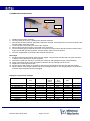
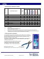
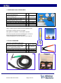
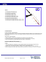
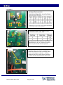
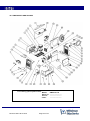
Instruction manual
& spare parts list
Unitor Welding Inverter
UWW-161 TP
Multi Process MIG-MAG-MMA-TIG
TP (total protection) version, from serial number 111194
Revision date: 26.02.2013
Page 1 of 32
DECLARATION OF CONFORMITY
₪₪₪₪₪₪₪₪₪₪₪₪₪₪₪₪₪₪₪₪₪₪₪₪₪₪₪₪₪₪₪₪₪₪₪₪₪₪₪₪₪₪₪₪₪₪₪₪₪₪
We hereby state that the machine type
UWW-161TP
TP (Total Protection)
version
s.n.: 111194 and higher
₪₪₪₪₪₪₪₪₪₪₪₪₪₪₪₪₪₪₪₪₪₪₪₪₪₪₪₪₪₪₪₪₪₪₪₪₪₪₪₪₪₪₪₪₪₪₪₪₪₪
is in compliance with the directives
2004/108/CE
2006/95/CE
₪₪₪₪₪₪₪₪₪₪₪₪₪₪₪₪₪₪₪₪₪₪₪₪₪₪₪₪₪₪₪₪₪₪₪₪₪₪₪₪₪₪₪₪₪₪₪₪₪₪
and that the following standards apply
EN 60974-1
EN 60974-5
EN 60974-10
₪₪₪₪₪₪₪₪₪₪₪₪₪₪₪₪₪₪₪₪₪₪₪₪₪₪₪₪₪₪₪₪₪₪₪₪₪₪₪₪₪₪₪₪₪₪₪₪₪₪
WECO srl
Via S. Antonio, 22 - BELVEDERE
36050 TEZZE SUL BRENTA (VICENZA) ITALY
Tel. +39 0424 561943 - Fax +39 0424 561944
E-mail [email protected] - www.weco.it
P. IVA 02783960244 - C.F. 02710490281
Reg. Impr. VI n° 52214 - R.E.A. N° 274736
Capitale sociale i.v. € 52.000,00
Belvedere, Maggio 2004
Amm. Giorgio TONIOLO
UWW-161TP s.n.: 111194 and higher is also in compliance with the
RoHS directive 2002/95 CE
Revision date: 26.02.2013
Page 2 of 32
CONTENTS
1. GENERAL DESCRIPTION
2. IDENTIFY COMPONENTS
3.
TECHNICAL DATA
4. INSTALLATION
5. FRONT PANEL
6. SPOOL COMPARTMENT
7. WIRE LOADING
8. OPERATING INSTRUCTIONS
9. WIRE WELDING CONSUMABLE SPARES
10. WIRE WELDING ACCESSORIES
11. SHIELDING GAS ACCESSORIES
12. TIG ACCESSORIES
13. MAINTENANCE
14. TROUBLESHOOTING
15. WIRING DIAGRAM
16. COMPONENTS AND SPARES
17. SAFETY INSTRUCTIONS
18. YOUR OWN NOTES
DO NOT INSTALL, OPERATE OR REPAIR THIS EQUIPMENT WITHOUT READING
THIS MANUAL AND THE SAFETY PRECAUTIONS CONTAINED THROUGHOUT
Revision date: 26.02.2013
Page 3 of 32
1. GENERAL DESCRIPTION
UWW-161 TP is a compact and portable Single Phase Inverter Power Source for professional MIG-MAG,
TIG and MMA welding.
It connects to a standard 230V one phase socket, preferably with slow fuses to allow full power.
The TP (total protection) version is protected against too high input voltage and will close down completely to
prevent damage if input voltage exceeds 285V. A led on the rear panel will be lit to indicate that the
protection is on. When the input voltage is reduced welding power will automatically be restored.
The automatic Voltage Reducing Function provides operator safety by reducing “touchable” voltage for the
operator to max. 10V between electrode holder and work-piece.
The automatic Amperage Draw Protection will cut the current to prevent damage to the machine, and sound
an alarm tone to warn the operator if welding with the set wire welding parameters exceeds the capacity of
the unit.
UWW-161 TP is easy to transport, only 12kg weight and it is specifically designed for light fabrication,
maintenance and repair work on board.
It offers excellent MIG-brazing characteristics using CuSi3 and CuSi6 type wires.
Polarity change for Euro-connector allows welding with self shielded wires.
User-friendly control panel allows precise parameters settings using only two knobs.
Selection between a softer and crisper arc allows optimal arc for various wires.
Built-in wind tunnel cooling protects electronic devices from dust and saltiness, improving the UWI-161 MP
arc welder’s life cycle.
• Light weight and reliable
• Up to 3,25mm electrodes in MMA
• Lift arc TIG DC ignition reduces Tungsten inclusions without generating the radio interference that High
frequency arc start may cause.
• Excellent MIG/MAG welding properties.
• Polarity selection for self-shielded wire welding.
Revision date: 26.02.2013
Page 4 of 32
2 IDENTIFY COMPONENTS
UWW-161 TP complete, product number 193-161161 is delivered with
1
Primary cable, 2.5m with plug (fitted on machine)
Gas hose socket with nut and hose clamp
1 piece
2
Product number 161165
1 set
Drive roll V groove, 0.6-0.8mm (fitted in machine)
3
Product number 160003
4
Outgoing wire guide tube for mounting in the wire drive unit 1 piece
MIG/MAG torch M-161 with 3m cable and euroconnector
1 piece
Product number 161163
Steel liner (fitted in torch cable)
1 piece
Product number 613746
Contact tip 0.8mm, (fitted in torch)
1 piece
Product number 711994
Return clamp with 3m cable and connector
1 set
Product number 633164
Electrode holder with 3m cable and connector
1 set
Product number 627877
Carrying strap for mounting on the machine
1 piece
Instruction Manual
1 piece
5
6
7
8
9
10
11
1 piece
10
1
11
2
3
4
8
5
6
7
Revision date: 26.02.2013
Page 5 of 32
9
3 TECHNICAL DATA
TP
The unique serial number for the
machine will be printed here.
Always give serial number when
ordering spares or in other
communication with WSS
concerning your machine.
Type of welding machine
One-phase static transformer rectifier
frequency converter, DC output.
Processes
MMA (Stick
electrode /
SMAW)
TIG
(GTAW)
MIG/MAG (Metal Inert Gas/Metal Active Gas)
GMAW (Gas Metal Arc Welding)
FCAW (Flux Cored Arc Welding)
Safety Marking
Suitable for use in areas with increased electric shock hazard
Revision date: 26.02.2013
Page 6 of 32
X: Duty cycle
Duty Cycle is percentage of 10 minutes that unit can weld at rated load without overheating.
It refers to a 40°C environmental temperature. If unit overheats a thermal switch stops the output, the
warning light for over-temperature is lit and the cooling fan continues to run. Wait fifteen minutes for unit to
cool. Reduce amperage or duty cycle before starting to weld.
I2= Welding current.
Range 5 – 140 / 160A
U0 = No-load voltage
Also called open circuit voltage, is the voltage (excluded any stabilization voltage or arc ignition) found
between the output outlets when the welding machine is not welding. This is the voltage a welder can be
exposed to between electrode holder and work piece.
U2 = Arc voltage
Voltage present between the output outlets when welding is being carried out, in relation to a particular set
current. The relation, for the various welding modes is the following:
MMA→U2=20+0,04*I2, TIG →U2=10+0,04*I2, MIG/MAG→U2=14+0,05*I2
Primary connection
U1
I1max
I1eff
= Effective input voltage 230V
= Maximum value of input current at the corresponding duty cycle.
= Effective value of input current at the corresponding duty cycle.
Cooling
COOLING AF= Forced air cooling (with a fan).
Protection class
IP23S= Ingress Protection class. Protection degree of the casing according to EN 60529
2: Protection against object not greater than 80mm in length and 12mm in diameter
3: Protection from sprayed water at an angle of 60º from vertical
S: Valid when switched off. If welding in heavy rain the cooling air can drag in moisture.
Thermal insulation class
I.CL.H= Thermal class of the insulating materials and insulation systems resistant up to 180°C.
Standards
EN 60974-10 European Norm for electromagnetic compatibility.
EN 60974-1/5 European Norm for arc welding appliance: Current sources for welding.
Mark stating conformity to all safety standards and other standards required for sale
within the European Union
Dimensions and weight
Height
Length
Width
Weight
: 325mm
: 460mm
: 230mm
: 12,2kg
Revision date: 26.02.2013
Page 7 of 32
4 INSTALLATION
Only qualified personnel should perform this installation.
Only personnel that have read and understood this Manual should install and operate this equipment.
The machine must only be plugged into a receptacle which is grounded per applicable electrical codes.
Note 1
The power switch is to be in the OFF position when installing work cable and torch and when connecting
power cord to input power.
Note 2
The parts behind the wire drive door are live when wire welding. Never open or leave this door open while
welding
SELECT SUITABLE LOCATION
The UWW-161TP has an IP23S rating. Locate the welder in a dry location where there is free circulation of
clean air into the back and out the front of the unit.
Ensure minimum 50cm free space from the back of the machine. If free flow of air is hindered the machine
will overheat.
A location that minimizes the amount of smoke and dirt drawn into the machine reduces the chance of dirt
accumulation that can block air passages and cause overheating.
AVOID TILTING
The machine must be placed on a secure, level surface, maximum 10º out of horizontal.
Gas inlet
ASSEMBLY
To the back panel
1
Primary connection 230V 50/60Hz 1phase
+ protective earth. 2,5m cable 3x2,5mm²
with plug is included
2
Gas Cylinder with Argon, Argon/CO2 or
CO2 (not included with machine)
3
Gas regulator with flow adjustment (not
included with machine)
4
Gas hose (not included with the machine)
5
Hose socket with nut and hose clamp for
6mm (1/4”) hose, included with the machine
On (I) OFF (0) Switch
LED indicating that
protection against too high
input voltage has been
activated
Important!
To prevent overheating the machine requires at least 0,5 m
free distance at the back to allow free flow of cooling air.
Inside the machine
6. Spool of welding wire
(not included with the machine)
7. Wire feed roll V-groove for 0,6-0,8mm wire
To the front panel
8.a MIG torch (included with the machine) to the Euro-connection
- then select polarity to the Euro-connection with the cable and Dix-connector on the front panel.
- then connect the return cable to the other polarity. MIG torch is included with the machine
8.b TIG torch (not included with the machine) to the Euro-connection
- then select – (negative) polarity to the Euro-connection with the cable and Dix-connector on the front panel.
- then connect the return cable to the + (positive) polarity
8.c Electrode holder (included with the machine) for MMA welding to the + or – socket depending on the type of
electrode to be used
8.d Return clamp (included with the machine) for all processes to the free (+ or -) socket.
Revision date: 26.02.2013
Page 8 of 32
8
POLARITY SELECTION
In the picture below the cable supplying current to the Euro-connector is connected to the machine plusconnection. The cable to return current (ground clamp) then has to be connected to the machine minusconnection to the right in the picture. This means the machine is set for welding with electrode plus polarity
from the Euro-connector to the right, which is the normal setting for MIG/MAG welding.
For Self-shielded wires (without shielding gas) and for TIG welding the minus polarity should normally be
selected, and the return clamp should be connected to the plus polarity.
For stick electrode welding (MMA) the cable in the picture is disconnected as shown in the drawing, and
electrode cable and return cable are connected to plus and minus according to the requirements of the
electrode that is going to be used.
The outgoing wire
guide tube is inserted
here, slightly bent to
prevent it from falling
out when the MIG
torch Euro-connector is
disconnected.
,
Revision date: 26.02.2013
Euro-connector for
TIG and MIG torch
_
Page 9 of 32
+
5 FRONT PANEL
1
2
6
7
4
3
5
8
1. Wire speed adjustment. See separate table under OPERATION for relation between wire speed and
approximate welding current. This adjustment is only active when one of the wire welding modes are
selected
2. When this LED is lit, it means that the thermal cut-out for overheating of the machine has triggered
and there is no welding current. Do not switch the machine off. The fan will be running and the
thermostat resets automatically when the machine has cooled down sufficiently. The light will darken
when the machine is live again.
When the machine is switched on, this LED is lit for five seconds, during which time there is no
welding current available.
3. Power on. When this LED is on welding current is available. In MMA (stick electrode) welding mode
the open circuit voltage of 10V is present between + and – terminals.
4. Warning light indicating live terminals
5. Welding current / voltage adjustment. The green scale A 5-140 show selected amperage for MMA
(stick electrode) welding. The white scale V 10-26 show selected voltage for MIG (wire) welding
6. Wire feed function. By pressing this knob wire will be fed through to the torch without being
electrically live.
Revision date: 26.02.2013
Page 10 of 32
7. This knob is active in the MIG/MAG mode only and allows selection between two arc types.
When the led above the knob is lit a softer welding arc for MIG brazing is obtained.
When the led is dark the normal, slightly crisper or harder arc is obtained.
8. Mode selection
2 step wire welding
• Bring the torch close to the piece you mean to weld.
• Press (step 1) and hold the torch button.
• The wire advances at closing speed until it contacts with the work-piece. The
welding arc is lit and the set wire feed speed will continue at set speed.
• Release the button (step 2) in order to start the welding completion procedure.
• The supply of gas continue for the selected post-gas time
4 step wire welding
• Bring the torch close to the piece you mean to weld.
• Press (step 1) and release (step 2) the torch button.
• The wire advances at closing speed until it contacts with the work-piece. The
welding arc is lit and the set wire feed speed will continue at set speed.
• Press (step 3) and release (step 3) the button in order to start the welding
completion procedure.
• The supply of gas continue for the selected post-gas time
MMA (stick) welding
In this mode a constant current characteristic for MMA welding is set and the
terminals are live (10V).
An automatic hot-start enables easy arc start. And an automatic arc-force maintains
a smooth and stable arc by momentarily increasing the current if bigger droplets in
the arc tends to produce short circuits.
An automatic anti-stick function will cut the power if the electrode should get stuck in
the melt-pool so that it can be removed without damage.
2 step TIG welding
• Touch the electrode to the piece you mean to weld.
• Press (step 1) and hold the torch button. Shielding gas and very small “signal”
current will start flowing.
• Lift the torch slowly, and the signal current will initialize an arc and an up-slope
function that increases the current to set value.
NOTE: The arc must be started within 3 seconds, if not the signal current will be
stopped to protect the circuit and a new start cannot be done before gas supply
has stopped.
• Release the button (step 2) in order to start the slope-down function that gradually
reduces the welding current to zero.
The supply of gas will continue for the selected post-gas time
Revision date: 26.02.2013
Page 11 of 32
6 SPOOL COMPARTMENT
Gas post-flows pot-meter the gas post-flow for MIG
and TIG can be adjusted from 0-3 seconds. It must
be long enough to ensure sufficient cooling of the
weld pool to avoid oxidation.
Fuse for the auxiliary transformer
providing current to the wire feed
motor: 800mA 250V slow fuse.
Wire feed system with drive rolls and
pressure adjustment.
Shaft for spool attachment and
Friction Brake Adjustment
The drive rolls have two grooves for two different wire sizes
Revision date: 26.02.2013
V-groove 0,60,8mm for solid
wires except
aluminium
GPS
Knurled Vgroove 1,0 (0,8) 1,2mm for fluxcored wires
GPS W 200
IALBRO W 237
ICUNI W 239
MS W 201
S 316 M-GF 221
S 309 M-GF 222
Page 12 of 32
U-groove 0,81,0mm for
aluminium wires
ALUMAG W 235
7 WIRE LOADING
Release the spring loaded pressure arm
(1) rotate the roll arm (2) up from the wire
feed drive roll (3).
1
Ensure that the groove size in the feeding
position on the drive roll matches the wire
type and size.
2
Place the wire spool in place on the wire
spool spindle (4). Make sure that the stud
(5) engages in the corresponding hole in
the wire spool
8
Check the Friction Brake Adjustment, a
bolt inside the spindle (6).
When properly adjusted, the brake should
provide only enough drag to prevent
overrun of the spool and excess slack in
the wire. Too much drag may result in
wire feeding problems,
S
3
Replace the cap (7).
Carefully detach the end of the wire from
the spool, cut the bent portion of wire off
and straighten the first 10cm.
Thread the wire through the ingoing guide
tube (8), over the drive roll (3), and into
the outgoing guide tube.
5
Close the idle roll arm (2) and latch the
spring loaded pressure arm (1) in place.
The roll pressure on the wire is adjusted
with the screw on the pressure arm. nut
above the spring. It should be sufficient to
ensure smooth feeding of the wire.
6
4
Rotate the spool counterclockwise if
required to take up extra slack in the wire.
7
Revision date: 26.02.2013
Page 13 of 32
8 OPERATING INSTRUCTIONS
Contact Tip
Nozzle
Torch Neck
1. Welding wire has been selected
2. Correct polarity to the torch / welding wire has been selected
3. Wire spool has been inserted, spool brake has been checked, wire inserted in the central connector, and
the idle roll arm has been closed.
4. Torch has been connected to the front of the machine
5. Return clamp has been properly connected to the work piece
6. Correct shielding gas (if required) has been connected to the gas inlet at the back of the machine and to
a gas cylinder with gas flow regulator, and the cylinder valve has been opened.
7. The wire compartment is closed and the machine switched on.
Next steps
8. Set the lowest wire feed speed, press the torch trigger. The gas solenoid valve will now open and allow
to adjust correct gas flow on the flow regulator.
9. Pull off the nozzle from the torch, unscrew the contact tip and straighten the gun cable assembly
10. Press wire feed knob (6) on the front panel to feed the wire out through the torch neck.
11. Replace the contact tip and nozzle.
12. Set wire speed and voltage in accordance with the wire specifications and proceed with the welding.
13. When finished, close the gas cylinder and press the trigger shortly to vent off gas pressure in hoses and
machine before switching off and unplugging.
Examples on parameter settings
Unitor Wire
Wire size
mm
Groove type
GPS W 200
MS W 201
S 316 M-GF 221
S 309 M-GF 222
Icuni W 239
Ialbro W 237
Alumag W 235
Alumag W 235
CuSi3Mn*
CuSi3Mn*
0,8
0,8
0.9
0.9
0,8
0,8
1,0
1,0
1,0
1,0
V
V-serrated
V-serrated
V-serrated
V
V
U
U
V
V
Wire
speed
m/min
7,5
12
11
13
7,5
7,5
12
7,5
7,5
5,5
*MIG brazing wire on request. Activate “soft arc” on the front panel for brazing
Revision date: 26.02.2013
Page 14 of 32
Volt
and
polarity
22V +
20V 22V +
24V +
22V +
22V +
23V +
22V +
22V +
18V +
Shielding
gas
Gas flow
Ar/CO2
No gas
Ar/CO2
Ar/CO2
Ar
Ar
Ar
Ar
Ar
Ar
10-15 l/min
22-25 l/min
22-25 l/min
15-20 l/min
15-20 l/min
15-20 l/min
15-20 l/min
15-20 l/min
15-20 l/min
9 WIRE WELDING CONSUMABLE SPARES
590075
613746
711986
711994
712000
712018
160001
WIRE FEED DRIVE ROLLS
0,6-0,8
o
X
o
X
X
0,8-1,0
1,0-1,2
X
o
X
o
WIRE FEED LINERS
Non iron liner *
0,6-1.2
X
X
X
X
X
Steel liner**
0,6-1,2
X
X
CONTACT TIPS
10 tips 0.6mm
0,6
X
X
X
X
X
10 tips 0.8mm
0,8
X
X
X
X
X
10 tips 1.0mm
0,9-1,0
X
X
X
X
X
10 tips 1,0-1.2mm (max 1mm al)
1,2
X
X
X
X
X
GAS NOZZLES
GAS NOZZLE
0,6-1,2
All wires requiring gas shielding
Drive roll V-groove
Drive roll U-groove
Drive roll V-groove knurled
Aluminum
wire
Solid wire
non-iron
Solid wire
stainless
Cored wire
stainless
Solid wires
steel
Cored wires
steel
Product Description
160003
160004
160005
X
O
*
**
Wire size mm
mm
Product number
Application area
o
X
X
**
**
**
X
= Well suited
= May be used, but not the best solution
= Not recommended, do not use
= Non iron liner can be used for all welding wires, but wears down quicker than steel liners
= Steel liner is a more wear resistant alternative for black steel welding but should be avoided for
stainless and non iron wires to avoid contamination of the weld.
10 WIRE WELDING ACCESSORIES
The Anti spatter spray prevents the spatter from the welding arc from sticking to
the metal surface adjacent to the weld. By spraying on a thin layer on each side of
where the welding is to take place, a barrier is formed preventing the molten
globules from burning on to the surface.
The spatter can easily be wiped off with a brush after welding. Time consuming
chipping and grinding is prevented. The spray is packed in an outer carton
containing 6 X 400 ml cans.
The multipurpose pliers provides means for spatter
removal from the nozzle inside, tip and outside.
It has jaws for contact tip and nozzle removal
and installation, and for cutting and pulling wire.
Multipurpose pliers for torch
pcs 193-591990
Anti Spatter Spray, 6 pcs of 400 ml in a box set 193-633149
Revision date: 26.02.2013
Page 15 of 32
11 SHIELDING GAS ACCESSORIES
Regulator with flow adjustment 0-32 l/min
for Argon and Mixed gas
Regulator with flow adjustment 0-32 l/min
for CO2 shielding gas
Gas hose ¼” black, for shielding gas
Hose clamps, one ear for ¼” hose, nonprotruding stainless, bag of 10 pcs
Pinching tool for ear clamps
Hose joint for 1/4" hose, 3/8" RH threads
Flowcontrol meter for use at torch nozzle
Flowcontrol needle valve for gas inlet
pcs
197 510010
pcs
193 510012
m
176 576157
set
401 729442
pcs
pcs
pcs
pcs
401 768507
176 175596
197 597328
197 597310
Argon / CO2 mix gas is used for steel and stainless steel
Pure Argon is used for all non iron metals.
Both gases are available in 10 and 50litre cylinders.
Pure CO2 may also be used as shielding gas, but only for
black steel with maximum thickness 2mm.
A special regulator for the CO2 cylinder is then required
12 TIG ACCESSORIES
TIG-Torch T-161 with 4m cable, euroconnector and torch mounted trigger
TIG accessories kit including short back
cap. spare heat-shield, collets, collet
bodies, nozzles and electrodes
Hose joint for 1/4" hose, 3/8" RH threads
Flowcontrol meter for use at torch nozzle
Flowcontrol needle valve for gas inlet
Revision date: 26.02.2013
pcs
197 160010
pcs
197 607810
pcs
pcs
pcs
176 175596
197 597328
197 597310
Page 16 of 32
1
Spares
2
1 197-551192 pcs Short back-cap
2 197-551200 pcs Long back-cap
3 197-613767 pcs Heat shield
4 197-551168 pcs Collet 1.6mm
4 197-551150 pcs Collet 2.4mm
5 197-551184 pcs Collet body 1.6 mm
5 197-551176 pcs CoIlet body 2.4 mm
6 197-551135 pcs Alumina nozzle 6
6 197-551127 pcs Alumina nozzle 7
7 197-674710 pck Tungsten electrode (10 pcs) 1.6 mm
7 197-674736 pck Tungsten electrode (10 pcs) 2.4 mm
3
7
4
5
6
13 MAINTENANCE
POWER SOURCE COMPARTMENT
In extremely dusty locations, dirt may clog the air passages causing the welder to run hot. Blow dirt out of the
welder with low pressure dry, oil-free air at regular intervals to eliminate excessive dirt and dust build-up on
interval parts.
WIRE FEED COMPARTMENT
1. When necessary, vacuum accumulated dirt from gearbox and wire feed section.
2. Occasionally inspect the incoming guide tube and clean inside diameter if necessary.
3. Motor and gearbox have lifetime lubrication and require no maintenance.
FAN MOTOR AND WIRE REEL SPINDLE
Requires no maintenance. Do not lubricate shaft.
TORCH
1. Check wire feed liner for damage or wear at regular intervals. This is especially important for the
non iron liner which may wear quickly if used for extensive shelf-shield welding
2. Replace worn contact tips as required. A variable arc is a typical symptom of a worn contact tip.
3. Remove spatter from inside of gas nozzle and from tip after each 10 minutes of arc time or as required.
Revision date: 26.02.2013
Page 17 of 32
14 TROUBLESHOOTING
PROBLEM
The machine
does not start.
CAUSE
− No current to the machine.
− Voltage reaches the
machine switch but there is
no voltage after the
contacts.
− There is voltage after the
switch but the machine
does not start
SOLUTION
• Make sure that power is available at the socket you
plug in to and that the power supply cable is intact.
• Unplug the machine and make sure that when the
machine is switched on, there is contact between the
contact input and output and that the varistor is not
broken. If so the power board must be replaced (pic.5).
• Check the mosfet of the switching power supply unit
on the power board (picture 6).
Make sure that power is available at the socket you plug
in to and that the power supply cable is intact.
• Check:
- varistors (picture 5);
- inverter (picture 4);
- Input bridge rectifier (picture 3);
- switching power supply unit (picture 6).
If one of these components is damaged replace the
power board 050.0011.0001.
Unplug the machine. Make sure the flat cable that connects the front panel to the power board is inserted
correctly. If correctly inserted, replace the front panel. If
the front panel does not activate, one of the switching
power supply unit outputs is broken. The power board
must be replaced.
• Check the mosfet of the switching power supply unit on
the power board. If it’s damaged it must be replaced
(picture 6).
• Unplug the machine
− Make sure that the wiring contact is correctly inserted
in the connector.
− Check for continuity between the +/- output outlets and
that the 2-path connector is connected to the front
panel (picture 1);
• The power board must be replaced
The line fuses
blow when the
switch is
activated and
the machine
does start.
− Damaged primary cable
or plug
− Damaged inverter
The front panel
is not activated.
− The fan works but the front
panel does not activate
− Both the fan and the front
panel do not work.
The
MMA/MIG/TIG
output voltage
is about 11V but
the machine
does not weld.
− The output voltage wiring
of the front panel is
interrupted (picture 1).
− The primary current alarm
on the power board is
activated
The output
voltage in each
mode is about
11V and
activating the
thermal
protection device.
Let the machine cool down. If
the machine continues
running with the protection
devices on, switch the
machine off and unplug the
machine. Remove the hood
and make sure the
temperature of the heat sink
part is less than 40°C;
If it is less than 40°C, check
that the thermal protective
device contacts are closed
as it should be.
- If one of the protection devices is permanently open it is
defective and must be replaced.
- If it is closed, make sure that the two terminals are well
inserted in the connector (picture 1).
- Power board feed problems, it must be replaced.
The machine is
dead except for
lit LED warning
light on the
back panel
Input voltage exceeds 285V
and the TP (total protection)
function has been activated
Nominal input voltage should be 230V. Welding power
will return automatically as soon as the input voltage has
been corrected.
Revision date: 26.02.2013
Page 18 of 32
PROBLEM
No output voltage
Primary fuses blow
The welding is not
optimal.
The machine stops
welding and emits
an acoustic signal
(sound alarm).
Non optimal wire
welding start.
No gas from the
solenoid valve
The torch button
does not work
The machine
always welds at
maximum current.
CAUSE
Check for a short circuit at
the DINSE plug with a
diode tester. A short
circuit may be caused by :
− damaged transil on the
snubber board;
− damaged diodes;
− damaged inverter;
− The inductive value of
the Power Transformer is
nill.
Settings have been set to
demand higher power
than available
− Spattering during
welding.
− Porosity in the deposit.
− Too narrow welding
seam (“dry arc”).
− Too wide welding seam
(“too hot weldpool”)
The maximum current that
can be supplied by the
machine has been
exceeded
Spattering and crackeling
occurs on starting.
− Excessive gas
pressure.
− Damaged solenoid
valve wiring.
− The solenoid valve
control relay on the front
panel is damaged.
− Solenoid valve is
damaged
− The amphenol board
(0042) cable is broken.
− The cable between the
euro connector and the
connector on front
panel.is broken
− The logic front panel
(pos 11) is damaged.
− The front panel is
damaged..
− The power board is
damaged.
− The shunt wires are
damaged or not correctly
inserted
Revision date: 26.02.2013
SOLUTION
Unplug the machine. Remove the snubber board:
• check with a diode tester the status of the transil on the
snubber board (picture 2);
• check with a diode tester the status of the diodes;
• check the status of the power board (picture 4);
• The Power Transformer must be replaced.
Decrease the welding current / wire speed / voltage
settings
• Make sure welding polarity is correct.
• Decrease the voltage and check the gas emission from
the torch.
• Increase the wire speed and/or voltage.
• Decrease the wire speed and/or voltage.
Decrease the value of the welding parameters.
Decrease the wire speed setting or increase voltage
setting
• Reduce gas flow setting.
• Unplug the machine, If break in a circuit, single out the
break and repair it. Make sure that the wiring contacts
are correctly inserted in the connectors.
• The logic front panel (pos 11) must be replaced.
• Should the operations carried out not have a positive
outcome, replace the solenoid valve (pos 35)..
Should the operations carried out not have a positive
outcome, try to replace the Toroidal Transformer (pos
21).
• The amphenol cable must be replaced.
• Check the connection between the Euro-connector and
pin 1/2 of the Amphenol connector.
- Then check the connection between the amphenol
connector and the motor board and between motor
board and front panel.
• The front panel must be replaced
Unplug the machine:
• The front panel must be replaced.
• The power board must be replaced.
• Connect the cables, or if damaged, replace them.
Page 19 of 32
PROBLEM
CAUSE
The wire feeding
unit motor does not
work.
− Primary fuse of the
auxiliary transformer is
damaged
− Control signals from the
front panel do not reach
the motor board.
− The motor board is
damaged.
SOLUTION
Unplug the machine. The delayed fuse 5x20 800 mA on
the back of the machine must be replaced.
• Check the connection of the motor feeding wire on the
front panel and after that check the continuity between
the front panel and the amphenol connector (picture 9).
Check connections between the front panel and the
white 4-pin connector; if connections are not interrupted,
replace the front panel.
• The motor board must be replaced.
PICTURE 1
Position of the connector in which they are inserted:
• thermal protection device : position 2, 5 (yellow
wires)
• Wire for the output voltage reading: position 3 (red)
• Shunt wire: pin 1/ 4.
Check the conductivity of contact of the thermal
protection device with the diode tester, with the heat
sink part temperature less than 40° C.
Check the conductivity between: + socket and the
shunt; - socket and the output voltage wire
PICTURE 2
Remove the snubber board and check that the transils
are not in short circuit.
At the ends of the two transils (see below) positioned
on the snubber board, “OL” must always be measured.
Revision date: 26.02.2013
Page 20 of 32
PICTURE 3
PICTURE 4
To check the inverter, carry out the following
measurements with a diode tester:
Should there be a short-circuit on one of these
measurements or an “OL” instead of a numeric
value, the power board must be replaced.
PICTURE 5
The varistor is a blue disc near the ground wire of
the power board. This device is necessary to
protect the board from input overvoltage. When
there is overvoltage it “explodes” , normally
causing a short circuit. If the extent of the short
circuit is very high its becomes an open circuit.
Revision date: 26.02.2013
Page 21 of 32
PICTURE 6
To check the mosfet of the switching power supply
unit, carry out the following measurements:
Should there be a short-circuit on one of these
measurements or an “OL” instead of a numeric
value, the power board must be replaced.
PICTURE 7
Digital multimeter. OL: Open Loop
Revision date: 26.02.2013
Page 22 of 32
15 WIRING DIAGRAM
Revision date: 26.02.2013
Page 23 of 32
16 COMPONENTS AND SPARES
For ordering spares please state:
Model:
Serial no:
Pos no:
Code:
Revision date: 26.02.2013
Page 24 of 32
UWW-161 TP
………............….
………….............
………............….
POS
CODE
DESCRIPTION
POS
CODE
DESCRIPTION
1
005.0001.0008
BELT
29
011.0010.0003
COIL BEARIN PLATE
2
011.0001.0188
UPPER COVER
30
011.0006.0050
SPOOL SUPPORT
3
015.0001.0001
HEAT SINK L=107mm
31
040.0006.1420
FUSE CARRIER
4
015.0001.0002
HEAT SINK L=50mm
32
050.0001.0043
DOUBLER OVERCUT BOARD
5
012.0001.0000
INTERNAL FRAMEWORKS
33
011.0010.0006
SWITCH PROTECTION PLATE
6
050.0011.0001
POWER BOARD
34
010.0006.0034
REAR PLASTIC PANEL
7
046.0002.0006
ELECTRICAL INSULATION
35
017.0001.5541
SOLENOID VALVE
8
012.0001.0007
INTERNAL PLASTIC SUPPORT
36
013.0007.0200
REAR PANEL
9
045.0005.0006
SHUNT
37
045.0000.0007
CABLE CLAMP
10
011.0010.0005
LOGIC PROTECTION PLATE
38
045.0002.0001
SUPLY CABLE
11
050.5052.2400
LOGIC FRONT PANEL
39
011.0002.0018
SOLENOID VALVE PLATE
12
014.0002.0008
KNOB
40
040.0001.0001
TWO-POLE SWITCH
13
021.0001.0229
FIXED SOCKET 200A
41
050.0001.0003
SNUBBER BOARD
14
021.0000.0003
KIT FOR GAS CONNECTORS
42
011.0006.0001
SLIDE CLOSURE
15
021.0001.0029
MOVABLE PLUG
43
012.0000.0001
SPOOL COVER
16
050.0001.0042
TORCH CONNECTOR BOARD
44
003.0002.0002
FAN
17
010.0006.0033
FRONT PLASTIC PANEL
45
011.0000.0208
DOOR PLATE
18
040.0003.1080
TERMAL SWITCH
46
010.0007.0001
PLANAR TRANSFORMER
19
021.0001.2001
COUPLING EURO
47
011.0006.0006
PLASTIC HINGE
20
002.0000.0005
WIRE FEED MOTOR
21
041.0006.0001
TOROIDAL TRANSFORMER
1
002.0000.0230
PRESSURE ARM COMPLETE
22
016.0009.0001
RUBBER FOOT
2
002.0000.0224
FIXING ARM COMPLETE
23
011.0010.0007
LOWER COVER
3
002.0000.0231
MOTOR COIL
24
011.0010.0008
INTERNAL SUPPORT PLATE
4
002.0000.0217
INLET GUIDE COMPLETE
25
015.0001.0004
HEAT SINK L=75mm
5
002.0000.0229
FEED PLATE
26
032.0002.0255
DIODE
6
002.0000.0232
DISTANCE RING
27
011.0010.0004
MOTOR PROTECTION PLATE
7
002.0000.0106
FEED ROLL
28
050.0001.0021
MOTOR BOARD
8
002.0000.0227
FIXING CAP
Revision date: 26.02.2013
WIRE FEED MECHANISM
Page 25 of 32
17 SAFETY INSTRUCTIONS
Arc Welding Hazards
The safety information given below is only a summary of the more complete safety information found in the
Safety Standards listed in Section 1-5. Read and follow all Safety Standards.
Only qualified persons should install, operate, maintain, and repair this unit. During operation, keep
everybody, especially children, away.
ELECTRIC SHOCK can kill.
Touching live electrical parts can cause fatal shocks or severe burns. The electrode and work circuit is
electrically live whenever the output is on. The input power circuit and machine internal circuits are also live
when power is on. In semiautomatic or automatic wire welding, the wire, wire reel, drive roll housing, and all
metal parts touching the welding wire are electrically live. Incorrectly installed or improperly grounded
equipment is a hazard.
Do not touch live electrical parts. Wear dry, hole-free insulating gloves and body protection. Insulate yourself
from work and ground using dry insulating mats or covers big enough to prevent any physical contact with
the work or ground. Do not use AC output in damp areas, if movement is confined, or if there is a danger of
falling. Use AC output ONLY if required for the welding process. If AC output is required, use remote output
control if present on unit.
Disconnect input power before installing or servicing this equipment. Always verify the supply ground −
check and be sure that input power cord ground wire is properly connected to ground terminal in the cord
plug and that the plug is connected to a properly grounded receptacle outlet. When making input
connections, attach proper grounding conductor first − double-check connections. Frequently inspect input
power cord for damage or bare wiring −replace cord immediately if damaged − bare wiring can kill. Turn off
all equipment when not in use.
Do not use worn, damaged, undersized, or poorly spliced cables. Do not drape cables over your body. If
earth grounding of the work-piece is required, ground it directly with a separate cable. Do not touch electrode
if you are in contact with the work, ground, or another electrode from a different machine.
Use only well-maintained equipment. Repair or replace damaged parts at once. Maintain unit according to
manual. Wear a safety harness if working above floor level. Keep all panels and covers securely in place.
Clamp work cable with good metal-to-metal contact to work-piece or worktable as near the weld as practical.
Insulate work clamp when not connected to work-piece to prevent contact with any metal object. Do not
connect more than one electrode or work cable to any single weld output terminal.
SIGNIFICANT DC VOLTAGE exists after removal of input power on inverters. Turn off inverter, disconnect
input power, and discharge input capacitors before touching any parts.
FUMES AND GASES can be hazardous.
Welding produces fumes and gases. Breathing these fumes and gases can be hazardous to your health.
Keep your head out of the fumes. Do not breathe the fumes. If inside, ventilate the area and/or use exhaust
at the arc to remove welding fumes and gases. If ventilation is poor, use an approved air-supplied respirator.
Read the Material Safety Data Sheets (MSDS) and the manufacturer’s instructions for metals, consumables,
coatings, cleaners, and degreasers.
Work in a confined space only if it is well ventilated, or while wearing an air-supplied respirator. Always have
a trained watchperson nearby. Welding fumes and gases can displace air and lower the oxygen level
causing injury or death. Be sure the breathing air is safe.
Do not weld in locations near degreasing, cleaning, or spraying operations.The heat and rays of the arc can
react with vapors to form highly toxic and irritating gases.
Do not weld on coated metals, such as galvanized, lead, or cadmium plated steel, unless the coating is
removed from the weld area, the area is well ventilated, and if necessary, while wearing an air-supplied
respirator. The coatings and any metals containing these elements can give off toxic fumes if welded.
Revision date: 26.02.2013
Page 26 of 32
ARC RAYS can burn eyes and skin.
Arc rays from the welding process produce intense visible and invisible (ultraviolet and infrared) rays that can
burn eyes and skin. Sparks fly off from the weld. Wear a welding helmet fitted with a proper shade of filter to
protect your face and eyes when welding or watching. Wear approved safety glasses with side shields under
your helmet. Use protective screens or barriers to protect others from flash and glare; warn others not to
watch the arc. Wear protective clothing made from durable, flame-resistant material (leather and wool) and
foot protection.
WELDING can cause fire or explosion.
Welding on closed containers, such as tanks, drums, or pipes, can cause them to blow up. Sparks can fly off
from the welding arc. The flying sparks, hot workpiece, and hot equipment can cause fires and burns.
Accidental contact of electrode to metal objects can cause sparks, explosion, overheating, or fire. Check and
be sure the area is safe before doing any welding. Protect yourself and others from flying sparks and hot
metal. Do not weld where flying sparks can strike flammable material. Remove all flammables within 35 ft
(10.7 m) of the welding arc. If this is not possible, tightly cover them with approved covers. Be alert that
welding sparks and hot materials from welding can easily go through small cracks and openings to adjacent
areas. Watch for fire, and keep a fire extinguisher nearby. Be aware that welding on a ceiling, floor,
bulkhead, or partition can cause fire on the hidden side. Do not weld on closed containers such as tanks,
drums, or pipes, unless they are properly prepared Connect work cable to the work as close to the welding
area as practical to prevent welding current from travelling long, possibly unknown paths and causing electric
shock and fire hazards. Do not use welder to thaw frozen pipes. Remove stick electrode from holder or cut
off welding wire at contact tip when not in use. Wear oil-free protective garments such as leather gloves,
heavy shirt, cuff-less trousers, high shoes, and a cap. Remove any combustibles, such as a butane lighter or
matches, from your person before doing any welding.
FLYING METAL can injure eyes.
Welding, chipping, wire brushing, and grinding cause sparks and flying metal. As welds cool, they can throw
off slag. Wear approved safety glasses with side shields even under your welding helmet.
BUILDUP OF GAS can injure or kill.
Shut off shielding gas supply when not in use. Always ventilate confined spaces or use approved airsupplied respirator.
HOT PARTS can cause severe burns.
Do not touch hot parts bare handed. Allow cooling period before working on gun or torch.
MAGNETIC FIELDS can affect pacemakers.
Pacemaker wearers keep away. Wearers should consult their doctor before going near arc welding, gouging,
or spot welding operations.
NOISE can damage hearing.
Noise from some processes or equipment can damage hearing. Wear approved ear protection if noise level
is high.
CYLINDERS can explode if damaged.
Shielding gas cylinders contain gas under high pressure. If damaged, a cylinder can explode. Since gas
cylinders are normally part of the welding process, be sure to treat them carefully. Protect compressed gas
cylinders from excessive heat, mechanical shocks, slag, open flames, sparks, and arcs. Install cylinders in
an upright position by securing to a stationary support or cylinder rack to prevent falling or tipping. Keep
cylinders away from any welding or other electrical circuits. Never drape a welding torch over a gas cylinder.
Never allow a welding electrode to touch any cylinder. Never weld on a pressurized cylinder − explosion will
result. Use only correct shielding gas cylinders, regulators, hoses, and fittings designed for the specific
application; maintain them and associated parts in good condition. Turn face away from valve outlet when
opening cylinder valve. Keep protective cap in place over valve except when cylinder is in use or connected
for use. Read and follow instructions on compressed gas cylinders, associated equipment, and CGA
publication P-1 listed in Safety Standards.
Revision date: 26.02.2013
Page 27 of 32
Additional precautions for installation, operation, and maintenance
Do not install or place unit on, over, or near combustible surfaces. Do not install unit near flammables. Do not
overload building wiring − be sure power supply system is properly sized, rated, and protected to handle this
unit.
FALLING UNIT can cause injury.
Use lifting eye to lift unit only, NOT running gear, gas cylinders, or any other accessories. Use equipment of
adequate capacity to lift and support unit. If using lift forks to move unit, be sure forks are long enough to
extend beyond opposite side of unit.
OVERUSE can cause OVERHEATING
Allow cooling period; follow rated duty cycle. Reduce current or reduce duty cycle before starting to weld
again. Do not block or filter airflow to unit.
STATIC (ESD) can damage PC boards.
Put on grounded wrist strap BEFORE handling boards or parts. Use proper static-proof bags and boxes to
store, move, or ship PC boards.
MOVING PARTS can cause injury.
Keep away from moving parts. Keep away from pinch points such as drive rolls.
WELDING WIRE can cause injury.
Do not press gun trigger until instructed to do so. Do not point gun toward any part of the body, other people,
or any metal when threading welding wire.
MOVING PARTS can cause injury.
Keep away from moving parts such as fans. Keep all doors, panels, covers, and guards closed and securely
in place.
H.F. RADIATION can cause interference.
High-frequency (H.F.) can interfere with radio navigation, safety services, computers, and communications
equipment. Have only qualified persons familiar with electronic equipment perform this installation.
The user is responsible for having a qualified electrician promptly correct any interference problem resulting
from the installation.
If notified about interference, stop using the equipment at once. Have the installation regularly checked and
maintained. Keep high-frequency source doors and panels tightly shut, keep spark gaps at correct setting,
and use grounding and shielding to minimize the possibility of interference.
ARC WELDING can cause interference.
Electromagnetic energy can interfere with sensitive electronic equipment such as computers and computerdriven equipment such as robots.
Be sure all equipment in the welding area is electromagnetically compatible.
To reduce possible interference, keep weld cables as short as possible, close together, and down low, such
as on the floor.
Locate welding operation 100 meters from any sensitive electronic equipment.
Be sure this welding machine is installed and grounded according to this manual.
If interference still occurs, the user must take extra measures such as moving the welding machine, using
shielded cables, using line filters, or shielding the work area.
Revision date: 26.02.2013
Page 28 of 32
Principal Safety Standards (US)
Safety in Welding, Cutting, and Allied Processes, ANSI Standard Z49.1, from American Welding Society, 550
N.W. LeJeune Rd, Miami FL 33126 (phone: 305-443-9353, website: www.aws.org ) . Recommended Safe
Practices for the Preparation for Welding and Cutting of Containers and Piping, American Welding Society
Standard AWS F4.1, from American Welding Society, 550 N.W. LeJeune Rd, Miami, FL 33126 (phone: 305443-9353, website: www.aws.org ) . National Electrical Code, NFPA Standard 70, from National Fire
Protection Association, P.O. Box 9101, 1 Battery March Park, Quincy, MA 02269−9101 (phone:
617−770−3000, website: www.nfpa.org and www. sparky.org ) . Safe Handling of Compressed Gases in
Cylinders, CGA Pamphlet P-1, from Compressed Gas Association, 1735 Jefferson Davis Highway, Suite
1004, Arlington, VA 22202−4102 (phone: 703−412−0900, website: www.cganet.com ) . Code for Safety in
Welding and Cutting, CSA Standard W117.2, from Canadian Standards Association, Standards Sales, 178
Rexdale Boulevard, Rexdale, Ontario, Canada M9W 1R3 (phone: 800−463−6727 or in Toronto
416−747−4044, website: www.csa−international. org ) . Practice For Occupational And Educational Eye And
Face Protection, ANSI Standard Z87.1, from American National Standards Institute, 11 West 42nd Street,
New York, NY 10036−8002 (phone: 212−642−4900, website: www.ansi.org ) . Standard for Fire Prevention
During Welding, Cutting, and Other Hot Work, NFPA Standard 51B, from National Fire Protection
Association, P.O. Box 9101, 1 Battery March Park, Quincy, MA 02269−9101 (phone: 617−770−3000,
website: www.nfpa.org and www. sparky.org ) . OSHA, Occupational Safety and Health Standards for
General Industry, Title 29, Code of Federal Regulations (CFR ) , Part 1910, Subpart Q, and Part 1926,
Subpart J, from U.S. Government Printing Office, Superintendent of Documents, P.O. Box 371954,
Pittsburgh, PA 15250 (there are 10 Regional Offices−−phone for Region 5, Chicago, is 312−353−2220,
website: www.osha.gov )
EMF Information
Considerations About Welding And The Effects Of Low Frequency Electric And Magnetic Fields Welding
current, as it flows through welding cables, will cause electromagnetic fields.
There has been and still is some concern about such fields.
However, after examining more than 500 studies spanning 17 years of research, a special blue ribbon
committee of the National Research Council concluded that: “The body of evidence, in the committee’s
judgment, has not demonstrated that exposure to power-frequency electric and magnetic fields is a humanhealth hazard.”
However, studies are still going forth and evidence continues to be examined. Until the final conclusions of
the research are reached, you may wish to minimize your exposure to electromagnetic fields when welding
or cutting.
To reduce magnetic fields in the workplace, use the following procedures:
1. Keep cables close together by twisting or taping them.
2. Arrange cables to one side and away from the operator.
3. Do not coil or drape cables around your body.
4. Keep welding power source and cables as far away from operator as practical.
5. Connect work clamp to work-piece as close to the weld as possible.
About Pacemakers:
Pacemaker wearers consult your doctor first. If cleared by your doctor, then following the above procedures
is recommended.
Revision date: 26.02.2013
Page 29 of 32
18 NOTES
................................................................................................................................................
................................................................................................................................................
................................................................................................................................................
................................................................................................................................................
................................................................................................................................................
................................................................................................................................................
................................................................................................................................................
................................................................................................................................................
................................................................................................................................................
................................................................................................................................................
................................................................................................................................................
................................................................................................................................................
................................................................................................................................................
................................................................................................................................................
................................................................................................................................................
................................................................................................................................................
................................................................................................................................................
................................................................................................................................................
................................................................................................................................................
................................................................................................................................................
................................................................................................................................................
Revision date: 26.02.2013
Page 30 of 32
USE THE UNITOR WELDING HANDBOOK FOR MARITIME WELDERS
You can download it here
http://www.wilhelmsen.com/services/maritime/companies/buss/DocLit/PorductLiterature/Pages/Maintenanceandrepair.aspx
…or contact Wilhelmsen Ships Service for a paper copy
Revision date: 26.02.2013
Page 31 of 32
Fraser/surrey Gaspe Gros Caouna Halifax Hamilton Harbour Grace Holyrood Kitimat Long Pond Marytown Montreal Nanaimo New
Westminster Bc Pictou/halifax Pointe Aux Pic.quebec Port Alfred Port Cartier Port Colborne Port Hawkesbury Port Mellon Port Moody
Port Of Quebec Port Weller Powell River Prince Rupert Roberts Bank Saint John Sarnia, Ontario Sept Iles Seven Islands Sorel Souris/
halifax Squamish St. Catherines St.john’s, Nfld St.romuald Stephensville Summerside/halifax
Three Rivers Thunder Bay Toronto
& spare part list
alleyfield Vancouver Victoria Weymouth Windsor Yarmouth Ancud / Laitec Antofagasta Arica Caldera Concepcion Bay Coquimbo
Coronel Corral Huasco Las Ventanas Lirquen Lota Penco Puerto Montt Puerto Williams Punta Arenas Quintero San Antonio San
Vicente Talcahuano Tocopilla Valparaiso Antilla Bahia Honda Banes Baracoa Cabanas Caibarien Cardenas Casilda Ceiba Hueca
Cienfuegos Guantanamo Guayabal Havana Isabel De Sagua Manati Mariel Media Luna Moa Nicaro Niquero Nuevitas Pilon Puerto
Padre Santiago De Cuba Sigloo Genoa Finn Tanamo Tunas De Zaza Vita Balao Esmeraldas Guayaquil La Libertad Manta Puerto
Bolivar Freeport/bahamas Guam Mahdia Acapulco Campeche Ciudad Del Carmen Coatzacoaloos Cozumel Dos Bocas Ensenada
Guaymas La Paz Lazaro Cardenas Mazatlan Progreso Puerto Vallarta Salina Cruz Tampico Topolobampo Tuxpan Vera Cruz Bonaire
Bullen Bay Curacao Aguadulce Almirante Armuelles Bahia Las Minas Balboa Cristobal Manzanillo Int.term. Vacamonte Callao
Chimbote Ilo Matarani Paita Pisco Guayama Guayanilla Mayaguez Ponce San Juan Yabucoa St. Vincent Chaguaramas La Brea Point
Fortin Point Lisas Pointe-a-pierre Port Of Spain Tembladora Aberdeen,wa Alameda Albany,n.y. Alexandria, Va Algiers Point Amelia
Anacortes, Wa Anchorage,ak Annapolis,md Antioch Aransas Pass Tx Astoria, Or Baltimore Baton Rouge Bayonne Baytown Beaumont
Bellingham, Ma Bellingham, Wa Benicia, Ca Boston, Ma Bridgeport Bridgeport, Conn Brooklyn, Ny Brownsville Tx Brunswick Brunswick,
Ga ucksport,me Buras Camden Camden, Nj Cameron La Chalmette Charleston, Sc Cheasapeake Chester Chicago Claymont Convent
Coos Bay, Or Corpus Chr.tx Crockett Darrow Davant Deer Park Delaware City Destrehan Donaldsonville Dutch Harbor, Ak Eastport, Me
Eureka Everett, Wa Fairless Hills Famagusta Ferndale,wa Freeport Tx Galveston Tx Garyville Geismar Georgetown, Sc Gloucester, Nj
Good Hope Gramercy Grand Isle Grays Harbour Gretna Gulfport, Ms Harvey Honolulu, Hawaii Hoquiam, Wa Houma Jacksonville
Kalama Kalama, Wa Kenai Key WestWe
Lakeservice
Charles Layour
Long Beach
Long
Longview, Wa Loop Terminal Los Angeles
needs
inIsland,
2 200Nyports…
Manchester, Wa Manhattan, Ny Marcus Hook, Pa Martinez Miami Mobile Morehead City Morehead City, Nc Morgan City Morrisville, Pa
Myrtle Grove Naples Nederland Tx New Haven, Conn New Iberia New London New Orleans New York Newington, Nh Newport News,
Va Newport, Or Newport, Ri Nikiski Norco Norfolk Oakland Olympia, Wa Orange, Rotterdam Tx Palm Beach Panama City, Fl
Pasadena Pascagoula, Ms Paulsboro, Nj Pennsauken, Nj Pensacola, Fl Petaluma Philadelphia Piney Point, Md Pittsburg Plaquemine
Point Comfort Tx Port Allen Port Angeles, Wa Port Arthur Tx Port Canaveral Port Everglades Port Hueneme Port Isabel Tx Port
Manatee, Fl Port Neches Tx Port Royal, Sc Port St. Joe, Fl Port Townsend, Wa Portland, Me Portland, Or Portsmouth Portsmouth, Nh
Providence, Ri Queens, Ny Redwood City Reserve Revere, Ma Richmond Richmond, Va Sacramento Salem Salem, Ma San Diego San
Francisco Sandwich, Ma Savannah Searsport, Me Seattle Seward Sparrows Point St.petersburg, Fl St.rose Staten Island, Ny Stockton
Tacoma, Wa Tampa Texas City The Bronx, Ny The Loop Valdez Vancouver, Wa Venice West Palm Beach Westville, Nj Wilmington, Ca
Wilmington, De Houston Wilmington,nc Yonkers, Ny Yorktown, Va Fray Bentos Jose Ignacio Montevideo Nueva Palmira Amuay Bay
Bajo Grande Cumarebo El Palito El Tablazo Guanta Guaranao Jose Bay La Guaira La Salina Maracaibo Pertigalete Puerto Cabello
Puerto La Cruz Puerto Miranda Puerto Ordaz Punta Cardon Punta De Palmas Punto Fijo San Lorenzo, Vz St.croix Aeroskobing Assens
Bagenkop Bogense Copenhagen Ebeltoft Enstedvaerket Havn Esbjerg Fakse Ladeplads Havn Fredericia Frederiksund Frederiksvaerk
Fredrikshavn Faaborg Gedser Great Belt Grenaa Graasten Gulfhavn Haderslev Halsskov Hanstholm Helsingor Hirtshals Hobro Holbaek
Horsens Kalundborg Kertminde Koge Kolding Korsor Lemvig Mariager Marstal Oslo Middlefart Naestved Nakskov Nyborg Nykobing
Falster Nykobing Mors Nykobing Skjaelland Odense Orehoved Falster Randers Ronne Rudkobing Sakskobing Skaelskor Skaerbaek
Skagen Skive Sonderborg Stege Stigsnaesvaerkets Havn Svendborg Studstrupvaerkets Havn Thisted Thorshavn Vejle Vordingborg
Aabenraa Aalborg Aarhus Kunda Loksa Muuga Paldiski Paljassaare Parnu Tallinn Dalsbruk Hamina/fr.havn Hanko/hangoe Helsinki
Ingaa/inkoo Jakobstad Kalajoki Kantvik Kaskinen/kasko Kemi Kemio Kokkola/karleby Kotka Koverhar Kristinestad Lappvik Lovisa
Mariehamn Merikarvia Nystad Naantali Oulu Pargas Pori Porvoo/borgaa Rauma Raahe/brahestad Skoeldvik Tammisaari Teijo Tolkis
Torneaa Turku Valkom/valko Vaasa Akureyri Isafjørdur Reykjavik Arklow Aughinish Bantry Cork Drogheda Dublin Dun Laoghaire
Dundalk Foynes Galway Limerick Moneypoint Ringaskiddy Tarbert Waterford Liepaja Mersrags Riga Roja Salacgriva Skulte Ventspils
Butinge Klaipeda Agnefest Alta Piraeus Arendal Asker Askoy Aukra Aure Averoey Bergen Berlevaag Bodoe Boemlo Brattvag Breivika
Brevik Baatsfjord Dirdal Drammen Dusavik Egersund Eide Elnesvaagen Eydehavn Fagerstrand Farsund Finnsnes Flekkefjord Floroe
Flaam Fosnavaag Fraena Fredrikstad Frei Gamvik Genoa Geiranger Gjemnes Glomfjord Gravdal Grimstad Gudvangen Halden Halsa
Hammerfest Harstad Haugesund Hellesylt Heroeya Hjelmeland Hoeyanger Holla Holmestrand Hommelvik Honningsvaag Horten
Husnes Jelsa Jessheim Joerpeland Joessinghamn Kambo Karmoey Kirkenes Singapore Krageroe Kristiansand Kristiansund
Kvinesdal Kyrksaeterora Kaarsto Larvik Leknes Lillesand Lyngdal Mandal Mehavn Mo I Rana Molde Mongstad Mosjoen Moss Muruvik
Maaloey Namsos Narvik Nesset Odda Oelen Oersta Orkanger Porsgrunn Rafnes Randaberg Raubergvika Risoer Sandefjord Sandnes
Sandnessjoen Sarpsborg Sauda Skien Skjervoey Slagen Slagentangen Smoela Soevik Sola Sorreisa Sortland Stavanger Stord Sture
Sunndalsoera Dubai Surnadal Svelgen Svolvaer Tananger Tau Thamshamn Tingvoll Tjeldbergodden Toensberg Tofte Tomrefjord
Tromsoe Trondheim Tustna Tvedestrand Tyssedal Tysvaer Ulsteinvik Vadsoe Vardoe Verdal Vik Volda Aagotnes Aaheim Aalesund
Aalvik Aardal i Ryfylke Aardalstangen Gdansk Gdynia Kolobrzeg Police Swinoujscie Szczecin Arkangelsk Baltiysk De Kastri Kaliningrad
Kandalaksha Kavkaz Kronshtadt Lomonosov Murmansk Nakhodka Novorossiysk Primorsk Sakhalin Sakhalin Severomorsk St.
Petersburg Svetlyi Taman Temruk Temryuk Tuapse Vladivostok Vostochniy, Port Vostochnyi Vyborg Bohus Brofjorden Falkenberg
Gavle Gothenburg Hallstavik Halmstad Helsingborg Hoganas Holmsund Hudiksvall Iggesund Kalmar Karlshamn Karlskrona Karlstad
Koeping Landskrona Lidkoping Lilla Edet Luleaa Lysekil Malmoe Mariestad Marstrand Munkedal Norrkoeping Norrsundet Norrtalje
Nynashamn Rotterdam Ornskoldsvik Oskarshamn Oxelosund Pitea Shanghai Simrishamn Skarhamn Skelleftehamn Skutskar Slite
Soderhamn Sodertalje Solvesborg Stenungsund Stockholm Stromstad Sundsvall Surte Trelleborg Uddevalla Umeaa Varberg Vastervik
Vasteraas Visby Wallhamn Ystad Aberdeen Appledore Arbroath Ardersier Ardrossan Avonmouth Ayr Ballycastle Banff Barking
Barnstaple Barrow In Furness Barry Barton On Humber Belfast Berwick Upon Tweed Billingham Birkenhead Blyth Boston Bowling
Braefoot Bay Bridgend Bridlington Bridport Bristol Briton Ferry Brixham Bromborough Buckie Burntisland Burton Upon Stather
Caernarvon Campbeltown Canvey Island Cardiff Carrickfergus Carrington Clacton On Sea Coleraine Connah’s Quay Coryton Cowes
Dagenham Dartford Dartmouth Dover Dundee Eastham
Ellesmere Port Erith Falmouth Faversham Fawley Felixstowe Finnart Fishguard Fleetwood Flixborough Folkestone Fort William Forth
Fowey
Fraserburgh Gainsborough Garston Gateshead Gillingham Girvan Glasgow Glasson Dock Glenrothes Gloucester Goole Gourock
Page 32 of 32
Grangemouth Revision date: 26.02.2013
Granton Gravesend Great Yarmouth Greenhithe Greenock Grimsby Guernsey Gunnesswww.wilhelmsen.com/shipsservice
Hamble Hartlepool Harwich Hebburn Heysham
Holyhead Hull Humber Hunterstone Immingham Invergordon Inverkeithing Inverness Ipswich Irvine Isle Of Grain Jarrow Jersey Kilkeel
Killingholme
Instruction manual