1
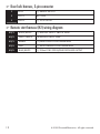
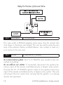
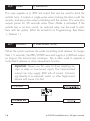
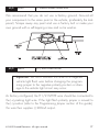
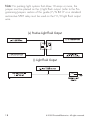
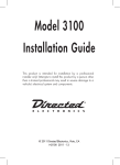
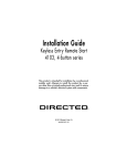
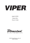
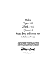
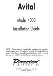
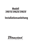
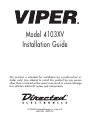
Model 4103XV Installation Guide This product is intended for installation by a professional installer only! Any attempt to install this product by any person other than a trained professional may result in severe damage to a vehicle’s electrical system and components. © 2009 Directed Electronics, Vista, CA N4103V 2009-07 Bitwriter®, Code Hopping™, Doubleguard®, ESP™, FailSafe®, Ghost Switch™, Learn Routine™, Nite-Lite®, Nuisance Prevention® Circuitry, Revenger®, Silent Mode™, Soft Chirp®, Stinger®, Valet®, Vehicle Recovery System®, VRS®, and Warn Away® are all Trademarks or Registered Trademarks of Directed Electronics. The Bitwriter® (p/n 998U) requires chip version 2.6 or newer to program this unit. Bitwriters with a date code of 6a or older require an IC upgrade (p/n 998M). Some Bitwriters with a date code of 6B do not require the IC upgrade. Refer to Tech Tip # 1112 for more information. Also required, the Bitwriter T-Harness included in the chip version 2.6 kit (998U). Contents Warning! Safety first..........................................................................................4 What is included................................................................................................7 Installation points to remember.............................................................................8 Virtual tach...............................................................................................9 D2D.........................................................................................................9 Component locations and finding wires..............................................................10 Making your wiring connections........................................................................10 Primary harness (H1) wiring diagram.........................................................11 4-pin satellite harness diagram..................................................................11 Heavy gauge relay wiring diagram...........................................................11 Door lock harness, 3-pin connector............................................................12 Remote start harness (H2) wiring diagram..................................................12 Primary harness (H1), 9-pin connector................................................................13 Heavy gauge relay interface.............................................................................19 Remote start harness (H2), 5-pin connector..........................................................20 Optional anti-grind relay..........................................................................23 Plug-in program switch......................................................................................23 Neutral safety switch interface...........................................................................24 D2D and programmer interface.........................................................................25 Programming jumpers.......................................................................................26 Light flash (+)/(-)......................................................................................26 Tach threshold on/off...............................................................................26 Virtual tach learning.........................................................................................27 Tach learning...................................................................................................28 To learn the tach signal.............................................................................28 Remote control learn routine..............................................................................29 Remote Configuration...............................................................................31 Operating settings learn routine.........................................................................32 Features menu.................................................................................................34 Menu 1..................................................................................................34 Menu 2..................................................................................................35 Feature descriptions..........................................................................................36 Menu 1..................................................................................................36 Menu 2..................................................................................................38 Timer mode, rear defogger.......................................................................41 Bitwriter®.......................................................................................................41 Owner recognition...................................................................................42 Shutdown diagnostics.......................................................................................43 Safety check....................................................................................................44 Troubleshooting...............................................................................................46 Notes.............................................................................................................49 Wiring quick reference guide............................................................................50 Warning! Safety first The following safety warnings must be observed at all times: • Due to the complexity of this system, installation of this product must only be performed by an authorized Directed Electronics dealer. • When properly installed, this system can start the vehicle via a command signal from the remote control. Therefore, never operate the system in an area that does not have adequate ventilation. The following precautions are the sole responsibility of the user; however, authorized Directed Electronics dealers should: • Never use a test light or logic probe when installing this unit. Always use a multimeter. • Never operate the system in an enclosed or partially enclosed area without ventilation (such as a garage). • When parking in an enclosed or partially enclosed area or when having the vehicle serviced, the remote start system must be disabled using the installed toggle switch. It is the user’s sole responsibility to properly handle and keep out of reach from children all remote controls to assure that the system does not unintentionally remote start the vehicle. • USER MUST INSTALL A CARBON MONOXIDE DETECTOR IN OR ABOUT THE LIVING AREA ADJACENT TO THE VEHICLE. ALL DOORS LEADING FROM ADJACENT LIVING AREAS TO THE ENCLOSED OR PARTIALLY ENCLOSED VEHICLE STORAGE AREA MUST REMAIN CLOSED AT ALL TIMES. Use of this product in a manner contrary to its intended mode of operation may result in property damage, personal injury, or death. Except when performing the Safety Check outlined in this Installation Guide, (1) Never remotely start the vehicle with the vehicle in gear, and (2) Never remotely start the vehicle with the keys in the ignition. The user is responsible for having the neutral safety feature of the vehicle periodically checked, wherein the vehicle must not remotely start while the car is in gear. This testing should be performed by an authorized Directed Electronics dealer in accordance with the Safety Check outlined in this product Installation Guide. If the vehicle starts in gear, cease remote start opera4 © 2009 Directed Electronics. All rights reserved. tion immediately and consult with the user to fix the problem immediately. After the remote start module has been installed, test the remote start module in accordance with the Safety Check outlined in this Installation Guide. If the vehicle starts when performing the Neutral Safety Shutdown Circuit test, the remote start unit has not been properly installed. The remote start module must be removed or properly reinstalled so that the vehicle does not start in gear. All installations must be performed by an authorized Directed Electronics dealer. OPERATION OF THE REMOTE START MODULE IF THE VEHICLE STARTS IN GEAR IS CONTRARY TO ITS INTENDED MODE OF OPERATION. OPERATING THE REMOTE START SYSTEM UNDER THESE CONDITIONS MAY RESULT IN PROPERTY DAMAGE OR PERSONAL INJURY. IMMEDIATELY CEASE THE USE OF THE UNIT AND REPAIR OR DISCONNECT THE INSTALLED REMOTE START MODULE. DIRECTED ELECTRONICS WILL NOT BE HELD RESPONSIBLE OR PAY FOR INSTALLATION OR REINSTALLATION COSTS. © 2009 Directed Electronics. All rights reserved. 5 What is included • • • • • • The control module (see diagram) XR Plus antenna receiver Two remote controls (P/N 7142V) A push-button Valet switch A hood pinswitch A shut-down toggle switch 4103XV © 2009 Directed Electronics. All rights reserved. 7 Installation points to remember Important: This product is designed for fuel-injected, automatic transmission vehicles only. Installing it in a standard transmission vehicle is dangerous and is contrary to its intended use. Before beginning the installation: • • • • Please read this entire Installation Guide before beginning the installation. The installation of this remote start system requires interfacing with many of the vehicle’s systems. Many new vehicles use low-voltage or multiplexed systems that can be damaged by low resistance testing devices, such as test lights and logic probes (computer safe test lights). Test all circuits with a high quality digital multi-meter before making connections. Do not disconnect the battery if the vehicle has an anti-theft-coded radio. If equipped with an air bag, avoid disconnecting the battery if possible. Many airbag systems will display a diagnostic code through their warning lights after they lose power. Disconnecting the battery requires this code to be erased, which can require a trip to the dealer. Remove the dome light fuse. This prevents accidentally draining the battery. Roll down a window to avoid being locked out of the vehicle. After the installation: • Test all functions. The “Using Your System” section of the Owner’s Guide is very helpful when testing. • Complete the vehicle Safety Check outlined in this manual prior to the vehicle reassembly. 8 © 2009 Directed Electronics. All rights reserved. ➢ Virtual tach Virtual Tach is the default RPM-sensing method for new remote start systems. Virtual Tach gives the installer the performance of a hardwired tach wire, with the convenience of voltage sensing. It is far superior to any voltage-sense feature you’ve tried before. Virtual Tach monitors the cranking voltage of the vehicle using a very fast micro-controller and an analog-to-digital converter. The microprocessor “saves” the base voltage as a reference. When Virtual Tach “sees” the slightest uptick in voltage, indicating that the alternator is charging the battery, the starter motor shuts off instantly. ➢ D2D The system has the ability to interface with an Xpresskit module through the D2D port. The advantage to using a D2D interface is that there is less wiring involved in the installation. Check the Xpresskit module Installation Guide to determine which wires are not needed, and which options are available. For more information see www.xpresskit.com. © 2009 Directed Electronics. All rights reserved. 9 Component locations and finding wires For detailed information on where to locate components, and how to find the wires you need, please refer to the Direct Tech web site at www.directechs.com. Making your wiring connections Before making your connections, plan how your wires will be routed through the vehicle. For instance, the red 12V constant input and the remote start ignition wires are often routed together to the ignition switch harness. In order to keep the wiring neat and make it harder to find, you may wish to wrap these wires together in electrical tape or conceal them in tubing similar to what the manufacturer used. There are two acceptable ways of making a wire connection - solder connections and crimp connectors. When properly performed, either type of connection is reliable and trouble-free. Regardless of whether you solder your connections or you use mechanical type crimp-on connections, ensure that all connections are mechanically sound and that they are insulated, especially when connecting data lines in the vehicle. Cheap electrical tape, especially when poorly applied, is not a reliable insulator. It often falls off in hot weather. Use good quality electrical tape or heat shrink. • Never twist-and-tape the wires together without soldering. • Never use “fuse taps”, as they can damage fuse box terminals. If you use tapping connectors such as T-Taps (not to be confused with Scotch-Locks), avoid using them in higher-current applications (constant 12V, ground, etc.) These connectors are inferior in quality and should be avoided. 10 © 2009 Directed Electronics. All rights reserved. ➢ Primary harness (H1) wiring diagram H1/1 LIGHT GREEN/ BLACK (-) 200mA FACTORY ALARM DISARM H1/2 GREEN/WHITE (-) 200mA FACTORY REARM H1/3 YELLOW (+) IGNITION OUT (TO ALARM) H1/4 WHITE/BLUE (-) ACTIVATION INPUT H1/5 ORANGE (-) 500mA GROUND WHEN LOCKED H1/6 BROWN (-) 200mA HORN OUTPUT H1/7 RED/WHITE (-) 200mA TRUNK RELEASE OUTPUT H1/8 BLACK GROUND H1/9 WHITE (+/-) LIGHT FLASH OUTPUT ➢ 4-pin satellite harness diagram 1 BLUE (-) 200mA STATUS OUTPUT 2 ORANGE (-) 200mA ACCESSORY OUTPUT 3 PURPLE (-) 200mA STARTER OUTPUT 4 PINK (-) 200mA IGNITION OUTPUT ➢ Heavy gauge relay wiring diagram 1 PINK (+) OUTPUT TO IGNITION CIRCUIT 2 PURPLE (+) OUTPUT TO STARTER CIRCUIT 3 ORANGE (+) OUTPUT TO ACCESSORY CIRCUIT 4 RED (+) (30A)) HIGH CURRENT 12 INPUT 5 PINK/WHITE (+) PROGRAMMABLE OUTPUT FOR ACCESSORY OR IGNITION 6 RED (+) (30A) HIGH CURRENT 12V INPUT © 2009 Directed Electronics. All rights reserved. 11 ➢ Door lock harness, 3-pin connector 1 BLUE (-) UNLOCK OUTPUT 2 EMPTY NOT USED 3 GREEN (-) LOCK OUTPUT ➢ Remote start harness (H2) wiring diagram 12 H2/1 BLACK/WHITE (-) NEUTRAL SAFETY SWITCH INPUT H2/2 VIOLET/WHITE TACHOMETER INPUT WIRE H2/3 BROWN (+) BRAKE SWITCH SHUTDOWN WIRE H2/4 GRAY (-) HOOD PINSWITCH SHUTDOWN WIRE H2/5 BLUE/WHITE (-) 200mA 2ND STATUS/REAR DEFOGGER OUTPUT © 2009 Directed Electronics. All rights reserved. Primary harness (H1), 9-pin connector H1/1 LIGHT GREEN/ BLACK (-) FACTORY ALARM DISARM This wire sends a 200mA negative pulse every time the remote start is activated or the doors are unlocked. This can be used to pulse the disarm wire of the vehicle’s factory anti-theft device. Use a relay to send a (-) or (+) pulse to the disarm wire as shown in the following diagram Relay for Negative (-) Disarm Wire © 2009 Directed Electronics. All rights reserved. 13 Relay for Positive (+) Disarm Wire H1/2 GREEN/WHITE (-) FACTORY REARM This wire sends a 200mA negative pulse every time the remote start shuts down or the doors are locked. This can be used to pulse the arm wire of the vehicle’s factory anti-theft device. Use a relay to send a (-) or (+) pulse to the arm wire. H1/3 YELLOW (+) IGNITION OUT (TO ALARM) As a stand-alone system: The H1/3 YELLOW wire should not be connected to anything. As an add-on car starter: If connected, disconnect the ignition/accessory input of the remote controlled security or keyless entry system. Connect the H1/3 YELLOW ignition output to the ignition/accessory input of the remote controlled security or keyless entry system. The wire will prevent the host system from sensing that the ignition is on during remote start operation. 14 © 2009 Directed Electronics. All rights reserved. H1/4 WHITE/BLUE (-) ACTIVATION INPUT This input comes from the factory set to 1 activation pulse. This means that it is necessary to have 1 ground pulse on the white/blue wire for the remote start to activate or to deactivate. It is not mandatory to connect this wire unless the remote start is being activated by a security or keyless entry system. An optional push button can also be connected to this wire to manually activate the remote start. Note: The activation pulse count can be programmed to 1, 2, or 3 pulses when changed it will affect both activation inputs; the White/ Blue wire and the remote control activation. H1/5 ORANGE (-) GROUND WHEN LOCKED OUTPUT This wire supplies a (-)500 mA ground as long as the system is locked and when the remote start is activated. (This feature can be turned off by programming the anti-grind option Off). This output ceases as soon as the system is unlocked. The ground-when-locked can be hooked up to an optional starter kill/anti-grind relay control module, a voice module or any accessory that requires a ground-when-armed. © 2009 Directed Electronics. All rights reserved. 15 H1/6 BROWN (-) HORN OUTPUT This wire supplies a (-) 200 mA output that can be used to honk the vehicle horn. It outputs a single pulse when locking the doors with the remote, and two pulses when unlocking with the remote. This wire also outputs pulses for 30 seconds when Panic Mode is activated. If the vehicle has a (+) horn circuit, an optional relay can be used to interface with the system. (Must be turned On in Programming: See Menu 1, Feature 1.) H1/7 RED/WHITE (-) TRUNK RELEASE OUTPUT When the system receives the code controlling trunk release, for longer than 1.5 seconds, the RED/WHITE wire will supply a (-) 200mA output as long as the transmission continues. This is often used to operate a trunk/hatch release or other relay-driven function. Important: Never use this wire to drive anything except a relay or low-current input! The transistorized output can only supply 200 mA of current. Connecting directly to a solenoid, motor, or other high-current device will cause it to fail. H1/7 RED/WHITE 16 © 2009 Directed Electronics. All rights reserved. H1/8 BLACK (-) CHASSIS GROUND CONNECTION We recommend that you do not use a factory ground. Ground all your components to the same point in the vehicle, (preferably the kick panel). Scrape away any paint and use a factory bolt or make your own ground with a self-tapping screw and a star washer. H1/9 WHITE (+/-) LIGHT FLASH OUTPUT Important: Do NOT connect this wire to a negative vehicle light flash wire before changing the programming jumper to the negative polarity position or damage to the vehicle light circuit may occur. As factory configured, the H1/9 WHITE wire should be connected to the (+) parking light wire. If the light flash polarity jumper is moved to the (-) position (refer to the Programming Jumper section of this guide), this wire then supplies (-) 200mA output. © 2009 Directed Electronics. All rights reserved. 17 Note: For parking light systems that draw 10 amps or more, the jumper must be placed on the (-) light flash output. (refer to the Programming Jumpers section of this guide.) P/N 8617 or a standard automotive SPDT relay must be used on the H1/9 light flash output wire. (+) Positive Light Flash Output (-) Light Flash Output 18 © 2009 Directed Electronics. All rights reserved. Heavy gauge relay interface The heavy gauge wires are used to energize the ignition circuits in the vehicle. It is crucial that these connections are made correctly so that they are capable of handling the current demands. For this reason, scotch locks, T-taps and other such connectors should not be used. 1 PINK (+) OUTPUT TO IGNITION CIRCUIT Connect this wire to the ignition wire in the vehicle. 2 PURPLE (+) OUTPUT TO STARTER CIRCUIT Connect this wire to the starter wire in the vehicle. 3 ORANGE (+) OUTPUT TO ACCESSORY CIRCUIT Connect this wire to the accessory wire in the vehicle that powers the climate control system. 4&6 RED (+) (30A) HIGH CURRENT 12 INPUT Remove the two 30 amp fuses prior to connecting these wires and do not replace them until the harness has been plugged into the control module. These wires are the source of current for all the onboard remote start relays and the main unit. They must be connected to a high current source. Since the factory supplies (+) 12V to the key switch that is used to operate the motor, it is recommended that these wires be connected there. Note: If the factory supplies two separate (+) 12V feeds to the ignition switch, connect one RED wire to each feed at the switch. © 2009 Directed Electronics. All rights reserved. 19 5 PINK/WHITE (+) PROGRAMMABLE OUTPUT FOR ACCESSORY OR IGNITION Connect this wire to the second ignition or accessory wire in the vehicle. (Selectable by using menu 2 feature 6.) Note: For vehicles that do not have a second ignition or accessory wire, this connection is not required. Remote start harness (H2), 5-pin connector H2/1 BLACK/WHITE (-) NEUTRAL SAFETY SWITCH INPUT Connect this wire to the toggle (override) switch as shown in Figure A. Connect the other wire from the toggle switch to the park/neutral switch in the vehicle. This wire will test with ground with the gear selector either in PARK or NEUTRAL. This will prevent the vehicle from accidentally being started while in a drive gear. This input MUST rest at ground in order for the remote start system to operate. Connected properly the vehicle will only start while in PARK or NEUTRAL. In some vehicles, the park/neutral position switch activates a factory starter lock-out that will not allow the starter to operate in a drive gear. In these vehicles, connect this wire to the toggle switch as shown in Figure B (see next page). Connect the other wire from the toggle switch to chassis ground. 20 © 2009 Directed Electronics. All rights reserved. Figure A Figure B Important! Always use the Vehicle Safety Check section of this guide to verify that the vehicle cannot be started in ANY drive gear and that the override switch is functioning properly. H2/2 VIOLET/WHITE TACHOMETER INPUT WIRE This input provides information to the unit about the engine’s revolutions per minute (RPMs). In vehicles with conventional coils this wire can be connected to the negative side of the coil - or to the non-common wire at the fuel injector. Once connected, you must teach the system the tach signal. (See Tach Learning section of this guide.) © 2009 Directed Electronics. All rights reserved. 21 H2/3 BROWN (+) BRAKE SWITCH SHUTDOWN WIRE This wire MUST be connected to the vehicle’s brake light wire. This is the wire that shows (+) 12V when the brake pedal is depressed. The remote start will be disabled or shut down any time the brake pedal is depressed. H2/4 GRAY (-) HOOD PINSWITCH SHUTDOWN WIRE This wire MUST be connected to the hood pinswitch. This input will disable or shut down the remote start when the hood is opened. H2/5 BLUE/WHITE (-) 2ND STATUS/REAR DEFOGGER OUTPUT This wire supplies a 200mA output as soon as the module begins the remote start process. This wire can also be used to activate the defogger trigger (latched/pulsed) 10 seconds after successful remote start. (See Menu 2 Feature 8, in the Feature Descriptions section for details) 22 © 2009 Directed Electronics. All rights reserved. ➢ Optional anti-grind relay The anti-grind relay prevents the starter from engaging if the ignition key is accidentally turned to the starter position during remote start operation. Plug-in program switch The Program switch plugs into the blue two-pin connector. BLUE 2-pin port R 4103XV © 2009 Directed Electronics. All rights reserved. 23 Neutral safety switch interface Some vehicles do not have an electrical neutral safety switch but instead have a mechanical neutral safety switch that physically interrupts the starter wire when the vehicle is in any drive gear. When the remote start is interfaced before this switch, it provides protection from starting in gear. However, some vehicles combine the column shift mechanism and the mechanical neutral safety switch into one mechanical part. Note: You must complete the remote start system installation before doing the following test. Ensure that the remote start system is functioning normally. This includes connecting to the brake as a shut-down. Testing the neutral safety switch 1. Make sure there is adequate clearance to the front and rear of the vehicle because it may move slightly. 2. Make sure the hood is closed and there are no remote start shutdowns active. 3. Set the emergency brake. 4. Turn the key to the “run” position, this will release the shifter. 5. Place the car in drive (D). 6. Place your foot directly over the brake pedal, but do not depress it. Be ready to step on the brake if the starter engages. 7. Activate the remote start system. 8. If the starter engages, immediately depress the brake to shut the remote start system down. If the starter does not engage, no additional safety system is required. If the starter engages and the vehicle is a General Motors product or Dodge Dakota pickup, you can find an alternative shut-down method to prevent the starter from engaging. Refer to www.directechs.com for Document 1008 under the Resource tab. 24 © 2009 Directed Electronics. All rights reserved. If the vehicle is not a General Motors product or a Dodge Dakota pickup, please call Directed Electronics Technical Support for an alternative shut-down method. Do not return the vehicle to the customer until this feature is properly installed! D2D and programmer interface The 4-pin red port is for interfacing with an Xpresskit module through D2D, or you can use it for programming with the Bitwriter®. If the Xpresskit module is unplugged so the port can be used for Bitwriter programming, you must unplug the heavy gauge 6 pin remote start harness before reconnecting the Xpresskit module back in. Once the Xpresskit module has been plugged in, reconnect the heavy gauge 6pin remote start harness and proceed to reprogram the Xpresskit module. For more information visit www.xpresskit.com. © 2009 Directed Electronics. All rights reserved. 25 Programming jumpers R 4103XV ➢ Light flash (+)/(-) This jumper is used to determine the light flash output polarity. In the (+) position, the on-board relay is enabled and the unit will output (+)12V on the WHITE wire, H1/9. In the (-) position, the on-board relay is disabled. The WHITE wire, H1/9, will supply a 200mA (-) output suitable for driving factory parking light relays. Note: For parking light circuits that draw 10 amps or more, the internal jumper must be switched to a (-) light flash output. P/N 8617 or a standard automotive SPDT relay must be used on the H1/9 light flash output harness wire. ➢ Tach threshold on/off In most cases, this jumper can be left in the OFF position. Some new vehicles use less than 12 volts in their ignition systems. The unit may have trouble learning the tach signal in these vehicles. Changing the jumper to the ON setting changes the trigger threshold of the digital tach circuit so it will work properly with these vehicles. 26 © 2009 Directed Electronics. All rights reserved. Virtual tach learning To program Virtual Tach: 1. After the install is complete, remote start the car. 2. If the car does not start on the first attempt, let the remote start attempt again. 3. Once the car starts, let it run until the parking lights come on. 4. When the parking lights come on, shut off the remote start with the remote - that’s it! Virtual Tach is programmed. Note: Virtual tach is not recommended for use on diesel trucks. Virtual Tach handles disengaging the starter motor during remote starting – it does not address over-rev. If the customer wants to have the over-rev protection capability the tach wire must be connected. This may involve more installation shop charges than initially quoted. Important: If the Virtual Tach mode over cranks or doesn’t crank the vehicle long enough to start and run the car, use the Bitwriter to add or subtract the starter output time. You can adjust the output time in increments of 50mSec of the learned time using the Bitwriter. © 2009 Directed Electronics. All rights reserved. 27 Tach learning Important: H2/2 Violet/white must be connected before this procedure is followed. ➢ To learn the tach signal 1. Start the vehicle with the key. DRW-96 2. Within 5 seconds, press and hold the Program switch. 3. The LED will light constant when the tach signal is learned. 4. Release the Program switch. 28 © 2009 Directed Electronics. All rights reserved. Remote control learn routine The system comes with two remote controls that have been taught to the system. The system can store up to 4 different remote control codes in memory. Use the following learn routine to add remote controls to the system. If the learn routines have been programmed using the Bitwriter®, they may have been locked. Before reprogramming the learn routines, you must unlock them with the Bitwriter. This cannot be done manually with the Valet switch. The Program switch, plugged into the blue port, is used for programming. There is a basic sequence of steps to remember whenever programming this unit: Key, Choose, Transmit and Release. 1. Key. Turn the ignition to the ON position. 2. Choose. Within 10 seconds, press and release the Program switch the number of times corresponding to the desired channel listed in the following table. Once you have selected the channel, press the switch once more and hold it. The LED will flash to confirm the selected channel. Do not release the Program switch. © 2009 Directed Electronics. All rights reserved. 29 Channel Function 1 Auto Learn Standard Configuration (default) The auto learn configuration automatically sets up the remote's button configuration. 2 Delete remotes: This feature erases all remotes from the memory of the system. This is useful in cases when a customer’s remote is lost or stolen. Note: This does not reset the programmed features of the system or reset the Virtual Tach setting. 3 Reset Features: This resets all of the system features to the factory default settings. Note: This feature does not delete the remotes from the system or reset the Virtual Tach setting. 4 Virtual Tach Reset: Deletes all previously learned values for Virtual Tach, and on the next remote start sequence the unit begins virtual tach initialization. Note: The “Zap” feature on the Bitwriter does not reset the Virtual tach setting. 3. Transmit. While holding the Program switch, press the button to program the remote or to reset one of the features in the remote programming grid. The horn honks to confirm that the code has been successfully programmed. It is not possible to teach a remote control to the system more than once. ������� 4. Release. Once the code is learned, the Program switch can be released. You can advance from programming one channel to another by releasing the Program switch and tapping it to advance steps and then holding it. For example, suppose you have programmed Channel One and you want to program Channel Two. Release the Program switch, then Press it one time and release it to advance from 30 © 2009 Directed Electronics. All rights reserved. Channel One to Channel Two. Now, press and hold the Program switch. The LED will flash two times, do not release it. Learn Routine will be exited if: • • • Ignition is turned off. Program switch is pressed too many times. More than 25 seconds elapses between programming steps. ➢ Remote Configuration 4-button remote control (included) Button Press Feature Lock, Panic On/Panic Off Unlock, Panic Off Trunk release � Remote Start Timer mode + ������� Car finder + ������� + ������� + Rear defogger See Owner’s Guide for details. © 2009 Directed Electronics. All rights reserved. 31 Operating settings learn routine The System Features Learn Routine dictates how the unit operates. The programmable operating settings of this unit can be changed whenever necessary through the computer-based Learn Routine. The Program push-button switch, plugged into the blue port, is used with a programmed remote control to change the settings. You can access and change all of the feature settings using the Program switch. To program settings, remember: Key, Choose, Transmit and Release. To enter the learn routine: 1. Key. Turn the ignition on and then back off. 2. Select menu. Press and hold the Program switch. When the LED flashes once and the horn honks once, Menu One has been selected. Continue to hold the switch until the LED flashes twice and the horn honks twice. Menu Two has now been selected. Release the Program switch after the desired Menu choice has been selected. 3. Choose. Within 10 seconds, press and release the Program switch the number of times corresponding to the feature number you want to program. (See Features menu section). Once the Program switch has been pressed and released the desired number of times, press it once more and hold it. After a second, the LED flashes and the horn honks to indicate which feature you have accessed. For example, groups of eight flashes and eight horn honks would indicate access to the status output Feature 8. 32 © 2009 Directed Electronics. All rights reserved. 4. Transmit. The remote control is used to select the desired setting. Pressing turns on the LED. Pressing on the remote will cycle through the available options in each feature. 5. Release. The Program switch can now be released. ������� ������� You can advance from feature to feature by pressing and releasing the Program switch the number of times necessary to get from the feature you just programmed to the feature you wish to access. For example, in Menu One, if you just programmed feature 1-3 to off, and you want to program the next feature 1- 4, release the Program switch. Press and release it once to advance from Feature 1-3 to Feature 1- 4. Then press it once more and hold it. The LED flashes in groups of 4 and the horn honks 4 times to confirm that you have accessed Feature 1- 4. The learn routine will be exited if any of the following occurs: • • • The ignition is turned on. The Program switch is pressed too many times. More than 25 seconds elapses between programming steps. © 2009 Directed Electronics. All rights reserved. 33 Features menu The factory default settings are indicated in bold text in the table below. ➢ Menu 1 Feature # Feature Opt. 1 Opt. 2 Opt. 3 Opt.4 Opt. 5+ 1 Honk pulses Off 20 mS 30 mS 40 mS 50 mS 2 Ignition controlled lock Off On 3 Ignition controlled unlock Off On 4 Doorlock pulse duration 0.8 sec. 3.5 sec. 5 Unlock output 1 pulse 2 pulses 6 Lock output 1 pulse 2 pulses 7 Factory Alarm Disarm function with unlock. Before unlock, remote start only 8 Factory Alarm Disarm 1 pulse 2 pulses 9 Comfort Closure Off Comfort Closure 1 Panic On Off 10 34 0.4 sec. Comfort Closure 2 © 2009 Directed Electronics. All rights reserved. ➢ Menu 2 Feature # Feature Opt. 1 Opt. 2 Opt. 3 Opt.4 1 Engine checking Virtual tach voltage Off tachometer 2 Run time 12 min 24 min 60 min 3 Park lights Constant Flashing 4 Crank time 0.6 sec. 0.8 sec. 1.0 sec. 3 pulses 5 Activation pulse 1 pulse 2 pulses 6 Ignition/accessory output Ignition Accessory 7 Acc state during wait to start Off On 8 2nd status output Normal latched 9 1.2 sec. 1.4, 1.6, 1.8, 2.0, 4.0 sec pulsed Anti-grind On Off 10 Wait to start time Off 15 sec 30 sec. 45 sec. 11 Timer mode run time 12 min 3 min 6 min 9 min © 2009 Directed Electronics. All rights reserved. Opt. 5+ 35 Feature descriptions The features of the system are described below with default settings in bold. ➢ Menu 1 1 HORN HONK PULSES—ON, OFF: Turns On/Off the confirmation honks when locking/unlocking. Use it to change the output pulse duration for vehicles that require a longer pulse for the horn to honk. Confirmation honks ON (20mS) & panic (1), Confirmation honk (30mS) & panic (2), Confirmation honk (40mS) & panic (3), Confirmation honk (50mS) & panic (4), Confirmation honk OFF. 2 IGNITION CONTROLLED LOCK—OFF, ON: When programmed ON the doors will lock 3 seconds after the ignition is turned on. 3 IGNITION CONTROLLED UNLOCK—OFF, ON: When programmed ON the doors will unlock automatically when the key is turned off. 4 DOOR LOCK PULSE DURATION—0.8, 3.5, 0.4 SECONDS: Some European vehicles, such as Mercedes-Benz and Audi, require longer lock and unlock pulses to operate the vacuum pump. Programming the system to provide 3.5 second pulses, will accommodate the door lock interface in these vehicles. The default setting is 0.8 second door lock pulses. Refer to TechTip 1041 for wiring information regarding Type E - Mercedes-Benz and Audi -1985 and Newer, diagram. The 0.4 second pulse is required on some of the newer Chrysler and Ford vehicles. 36 © 2009 Directed Electronics. All rights reserved. 5 UNLOCK OUTPUT—1, 2 PULSES: This programs the unlock output to one or two pulses. When in two pulse setting, the BLUE unlock wire supplies two negative pulses instead of a single pulse. This makes it possible to directly interface with double pulse vehicles without any extra parts. 6 LOCK OUTPUT—1, 2 PULSES: This programs the lock output to one or two pulses in two pulse setting. The GREEN lock wire supplies two negative pulses instead of a single pulse. This makes it possible to directly interface with double pulse vehicles without any extra parts. 7 FACTORY ALARM DISARM—WITH UNLOCK, BEFORE UNLOCK, REMOTE START ONLY: In the default setting the factory alarm disarm output will disarm the factory alarm system any time the buttons controlling Unlock is pressed. The “Before Unlock” output disarms the factory alarm before the unlock output activates and before remote start is activated. The “Remote Start Only” output disarms the factory alarm only before the remote start is activated. 8 FACTORY ALARM DISARM PULSES—1, 2 PULSES: Selectable for a single or double-pulse for the vehicle’s factory alarm disarm input requirements. 9 COMFORT CLOSURE—OFF (1): The system can be programmed to close the windows when the system is locked. If programmed ON, the lock output provides a 20 second pulse when the system is locked. The output will be cancelled if the unlock button is pressed. In the Off setting the system will not do this function. (2) Comfort closure 1 - Activates the 20 second timer after the door lock pulse. (3) Comfort Closure 2 - Activates the 20 second timer with the door lock pulse. © 2009 Directed Electronics. All rights reserved. 37 10 PANIC ON/Off: When on, the panic feature can be activated at any time from the remote and will sound for 30 seconds. When off the panic feature does not function. ➢ Menu 2 1 ENGINE CHECK— VIRTUAL TACH(1) /VOLTAGE(2) /OFF(3) /TACHOMETER (4) When set to “virtual tach” (1) the remote start monitors the cranking voltage of the vehicle and sets it as a reference point. Fifteen seconds after the crank output sequence the remote start checks the voltage again to determine if the vehicle is running. When set to voltage, (2) the unit cranks the starter for the programmed time and then attempts to sense that the engine is running by detecting an increase in voltage. If programmed Off (3) the vehicle cranks for the programmed crank time. The tach setting or voltage setting is not checked to verify that the car is running. In the OFF setting, if the vehicle fails to start, the ignition stays on for the run duration. Using tach or either of the voltage settings is recommended. When set to Tachometer, (4) the unit references the learned tach signal to disengage the starter. In addition it will monitor the RPM and shut down if the engine RPM is too high or too low. 2 RUN TIME—12/24/60 MINUTES: This feature controls how long the engine will run before it “times out” and shuts down. Programmed to the default setting the engine will run for 12 minutes. If the 24 or 60 minute run time is desired, change this feature to the two or three flash setting. 38 © 2009 Directed Electronics. All rights reserved. 3 PARKING LIGHTS—CONSTANT/FLASHING: In the default setting, the parking lights will come on solidly for the entire run duration. In the flashing setting, the parking lights will flash for the entire run duration. 4 CRANK TIME—0.6/0.8/1.0/1.2/1.4/1.6/1.8/2.0/4.0 Seconds: If Feature 2 is programmed to the voltage sense setting, the crank time must be set to the appropriate duration. The default setting is 0.6 second. If a different crank time is desired, press the button to advance through the LED Off settings. The unit will flash the LED to indicate which time is selected. Once the 4.0 second setting is reached the next press of the button will reset the system to the shortest setting. ������� 5 ACTIVATION PULSE COUNT—1/2/3 PULSES: This feature allows the number of pulses to activate the remote start feature to be changed from 1, 2, or 3 pulses. The pulse count programmed to start the vehicle will also be the same required to shut down the remote start. ������� 6 2nd—IGNITION/ACCESSORY OUTPUT: This will allow the PINK/WHITE to be used as a 2nd ignition or a 2nd accessory. 7 ACCESSORY STATE DURING WAIT-TO-START—OFF/ON: This will allow the programming of the accessory wire during the waitto-start period of a diesel motor. When ON the accessory comes on when the wait-to-start timer is activated and stays on, dropping out during crank and returning once the car has started. When OFF the accessory will not activate during the wait-to-start period. © 2009 Directed Electronics. All rights reserved. 39 8 2nd STATUS OUTPUT—NORMAL/LATCHED/PULSED: If programmed to normal mode, this output turns on when the remote start is activated. This output can be programmed as a Latched or Pulsed output and can be used to activate the rear defroster when the vehicle is remote started. When programmed to the latched output the status only stays active for 10 minutes. When programmed to the pulsed output the status sends out a single pulse. When programmed for the latched or pulsed mode the output activates 10 seconds after the remote start is running. 9 ANTI-GRIND ON/OFF: With the anti-grind On (default) the ground-when-locked output will be active during remote start operation. This activates an optional relay and prevents the customer from re-cranking the car with the key, when doing key takeover. If accessories such as a voice module or window module are added to the unit, it may be necessary to use the two-honk setting to program this feature OFF. 10 WAIT-TO-START TIME OFF/15, 30, 45 SECONDS: The diesel wait-to-start timer default is in the OFF setting. When programmed ON the onboard timer can be set for 15, 30 or 45 seconds. 11 RUN TIME (TIMER MODE)—12, 3, 6, 9 MINUTES: Selects the time in minutes that the system will operate the engine when timer mode activates the remote start. During the runtime the remote start can be shut down with any of the shutdown inputs. Using the Bitwriter the run time can be programmed for any duration from 1-16 minutes. 40 © 2009 Directed Electronics. All rights reserved. ➢ Timer mode, rear defogger For information on Timer Mode and Rear Defogger mode, refer to the Owner’s Guide at www.directed.com. Bitwriter® The Bitwriter has the ability to fine tune certain features of the system. These features and the adjustments that may be programmed are described in the table below. The Bitwriter T-Harness included in the chip version 2.6 kit (998U) is required for Bitwriter programming. Feature Default setting Optional settings Remote start runtime 12 minutes 1-60 minutes Diesel start delay Off Timed Diesel start timer 15 seconds 1-90 seconds Virtual tach fine tune Not initialized 0 to 1 second in 50ms increments. Remote control programming Unlocked Locked Feature programming Unlocked Locked © 2009 Directed Electronics. All rights reserved. 41 ➢ Owner recognition Owner recognition is a revolutionary feature available only from Directed. Using the Directed Bitwriter you can program different settings for each transmitter used with the system. Then, when a specific transmitter is used the settings assigned to it are recalled. Up to four users may have settings to meet their specific needs. It is almost like having four separate alarms in the vehicle, one for each user. When using Owner recognition with the Bitwriter the following are the only applicable features: • • • • Horn function Ignition locking Ignition unlocking Activation pulses for remote start Important: Owner recognition cannot be programmed without a Bitwriter and the necessary software. 42 © 2009 Directed Electronics. All rights reserved. Shutdown diagnostics The unit has the ability to report the cause of the last shutdown of the remote start system. To enter diagnostic mode: 1. Turn the ignition off. 2. Press and hold the Program switch. 3. Turn the ignition on and then off. 4. Release the Program switch. 5. Press and release the Program switch. The LED reports the last system shutdown by flashing for one minute in the following grouped patterns and stops flashing when the ignition is turned on. © 2009 Directed Electronics. All rights reserved. 43 Shutdown Flash Patterns led flashes 1 2 3 4 5 6 7 shutdown mode System timed out Over-rev shutdown Low or no RPM, Low battery (for voltage & Virtual tach modes) Remote control shutdown (or optional push button) (-) Hood shutdown (+) Brake shutdown Neutral safety Safety check Before vehicle reassembly, the remote system must be checked to ensure safe and trouble-free operation. The following test procedure must be used to verify proper installation and operation of the system. The installation must be completed before testing, including connection to the brake switch and hood switch. 1. Test the BRAKE shutdown circuit: With the vehicle in Park (P), activate the remote start system. Once the engine is running, press the brake pedal. The engine should shut down immediately. If the engine continues to run, check the brake circuit connection. 2. Test the HOOD PIN shutdown circuit: With the vehicle in Park (P), open the hood. Activate the remote start system. The vehicle should not start. If the starter engages, check your hood pin and connections. Note: If programmed for Diesel Mode, the system will turn on the ignition, but the starter should not engage with the hood open. 44 © 2009 Directed Electronics. All rights reserved. 3. Test the NEUTRAL SAFETY shutdown circuit: Important: Make sure there is adequate clearance to the front and rear of the vehicle before attempting this test. a.Make sure the hood is closed and no other shutdown circuits are active. b.Set the emergency brake. c.Turn the ignition key to the run position but do not start the engine. d.Put the vehicle in Drive (D). e.Put your foot over the brake pedal but do not press down on it. Be ready to step on the brake to shutdown the remote start system. f. Activate the remote start system. • If the starter engages, immediately step on the brake to shut down the system. If it does engage, recheck the neutral safety input connection. The vehicle may use a mechanical neutral safety switch. (See H2/1 BLACK/WHITE neutral safety switch input in Remote Start Harness Wire Connection Guide section of this guide.) • If the starter does not engage, the test is complete. Once the system passes all three tests, the vehicle can be re-assembled and delivered. Do not use the remote start system or finalize the installation if it fails any of the safety check tests. © 2009 Directed Electronics. All rights reserved. 45 Troubleshooting • The starter cranks for six seconds but does not start. Either the wrong ignition wire is being energized, the system’s ignition and accessory wires have been connected backwards, or the vehicle has two ignition circuits. Try activating the unit with the ignition key in the “run” position. If the vehicle then runs normally, retest your ignition system. • The climate control system does not work while the unit is operating the vehicle. Either the wrong accessory wire is being energized or more than one ignition or accessory wire must be energized in order to operate the climate control system. • The remote start will not activate. 1. Check harnesses and connections. Make sure the harnesses are fully plugged into the remote start module. Make sure there are good connections to the vehicle wiring. 2. Check voltage and fuses. Also make sure that the ground wire is going to a chassis ground and not to something under the dash. 3. Check diagnostics. The diagnostics will tell you which shutdown is active or not connected. • The remote start will activate but the starter never engages. 1. Check for voltage on the purple starter wire two seconds after the remote start becomes active. If there is voltage present, skip to Step 4. If there is not voltage present, advance to Step 2. 2. Check the 30A fuses. 3. Make sure the purple starter wire is connected on the starter side of the optional anti-grind relay. 46 © 2009 Directed Electronics. All rights reserved. 4. Does the vehicle have an immobilizer? Some immobilizer systems will not allow the vehicle to crank if active. 5. Check connections. The two red heavy gauge input wires on the relay satellite should have solid connections. “T-taps”, or “scotch locks” are not recommended for any high current heavy gauge wiring. Also, if the vehicle has more than one 12-volt input wire, then connect one red wire to each. • The vehicle starts, but immediately dies. 1. Does the vehicle have an immobilizer? The vehicle’s immobilizer will cut the fuel and/or spark during unauthorized starting attempts. 2. Is the remote start programmed for voltage sense? If so, the start time may not be set high enough, or you may have to adjust the voltage threshold in programming. Voltage sense will not work on some vehicles. 3. Check diagnostics. Sometimes a shutdown will become active during cranking or just after cranking. • The vehicle starts, but the starter keeps running. 1. Is the system programmed for engine checking off or voltage sense? When programmed for either of these features, the engine cranks for the pre programmed crank time regardless of how long it takes to start the vehicle to actually start. Adjust to a lower cranking time. 2. Was the Tach Learn successful? The LED must light solidly and brightly to indicate a successful learn. 3. Make sure that there is a tach signal right at the purple/white tach input wire of the remote start. If not, recheck the connection to the vehicle’s tach wire and make sure the wire is not broken or shorted to ground leading to the remote start. © 2009 Directed Electronics. All rights reserved. 47 • The vehicle will start and run only for about 10 seconds. 1. Is the remote start programmed for voltage sense? Try programming the unit for low voltage reference. If this does not work, a tach wire should be used. 2. Check diagnostics. 48 © 2009 Directed Electronics. All rights reserved. Notes © 2009 Directed Electronics. All rights reserved. 49 Wiring quick reference guide BROWN (-) 200mA horn honk output BLUE/WHITE (-) 200mA 2ND status output/defogger Off On 50 © 2009 Directed Electronics. All rights reserved. ORANGE (-) 500 mA ground when locked GREEN/WHITE (-) 200mA factory alarm rearm GREEN/BLACK (-) 200mA factory alarm disarm red 4 pin d2d bitwriter port © 2009 Directed Electronics. All rights reserved. 51 The company behind this system is Directed Electronics Since its inception, Directed Electronics has had one purpose, to provide consumers with the finest vehicle security and car stereo products and accessories available. The recipient of nearly 100 patents and Innovations Awards in the field of advanced electronic technology. Directed is ISO 9001 registered. Quality Directed Electronics products are sold and serviced throughout North America and around the world. Call (800) 274-0200 for more information about our products and services. N4103V 2009-07 Vista, CA 92081 www.directed.com © 2009 Directed Electronics—All rights reserved