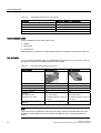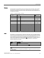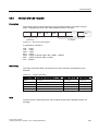
1
s
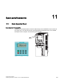
Product Information
SINAMICS G120
SINAMICS G120D
SIMATIC ET 200S FC
SIMATIC ET 200pro FC
Edition 06/2007
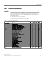
This product information sheet describes the behavior of the above mentioned inverters
(Firmware version V3.0), that is not described in the associated documentation, edition
06/2007, Firmware version 3.0.
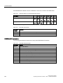
All inverters
If in sensorless vector control (SLVC) one of the following problems appears
• motor does not ramp up
• setpoint jumps at low frequencies at ramp down
• motor does not ramp down to 0 Hz even if torque limit is set to 0
• the calculated motor temperature (P0621 > 0) shown in r0035 is implausible
this can be caused by faulty values for both, stator and motor cable resistance.
Try the following to solve the problem:
• disconnect the motor from the feeder cable,
• measure the stator resistance and the motor cable resistance with an ohmmeter or
better with a wheatstone bridge
• put the values in P0350 (stator resistance) and P0352 (cable resistance),
• then perform "calculation of motor parameters" again with P0340 = 3.
If you don' not get feasible values measuring the stator resistance, use the equivalent
circuit data of the motor (this can be can be provided by the motor manufacturer) and
write it into the respective parameters (fig 6.1 in Function Manual) or reduce the stator
resistance in 5 % steps and perform "calculation of motor parameters" again with
P0340 = 3.
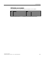
Fail-safe inverters
If activating SS1 or SLS, this triggers the STO signal as a pulse. This STO pulse has no
influence on the SS1 or SLS function and can be ignored.
CU240S PN
If in HW config of STEP 7 a different telegram type is selected from the telegram type
selected in P0922 in the inverter, the inverter trips - by fault - with F00452 (belt failure). If
this fault occurs then check the telegram set in HW config and P0922.
Power Modules PM260
With Power Modules PM260 "motor temperature identification" (P0621) only works with a
KTY sensor.
Product Information - Function Manual
SINAMICS G120, SINAMICS G120D, SIMATIC ET 200S FC, SIMATIC ET 200pro FC
Introduction
1
Safety notes
2
SINAMICS
Description
3
G120
Control Units CU240S
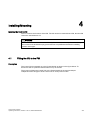
Installing/Mounting
4
Commissioning
5
Communication
6
Operation
7
Troubleshooting
8
Service and maintenance
9
Operating Instructions
Edition 06/2007, Software version V3.0
06/2007 - SW 3.0
A5E00766042B AB
Technical data
10
Spare parts/Accessories
11
Appendix
A
List of abbreviations
B
Safety Guidelines
This manual contains notices you have to observe in order to ensure your personal safety, as well as to prevent
damage to property. The notices referring to your personal safety are highlighted in the manual by a safety alert
symbol, notices referring only to property damage have no safety alert symbol. These notices shown below are
graded according to the degree of danger.
DANGER
indicates that death or severe personal injury will result if proper precautions are not taken.
WARNING
indicates that death or severe personal injury may result if proper precautions are not taken.
CAUTION
with a safety alert symbol, indicates that minor personal injury can result if proper precautions are not taken.
CAUTION
without a safety alert symbol, indicates that property damage can result if proper precautions are not taken.
NOTICE
indicates that an unintended result or situation can occur if the corresponding information is not taken into
account.
If more than one degree of danger is present, the warning notice representing the highest degree of danger will
be used. A notice warning of injury to persons with a safety alert symbol may also include a warning relating to
property damage.
Qualified Personnel
The device/system may only be set up and used in conjunction with this documentation. Commissioning and
operation of a device/system may only be performed by qualified personnel. Within the context of the safety notes
in this documentation qualified persons are defined as persons who are authorized to commission, ground and
label devices, systems and circuits in accordance with established safety practices and standards.
Prescribed Usage
Note the following:
WARNING
This device may only be used for the applications described in the catalog or the technical description and only
in connection with devices or components from other manufacturers which have been approved or
recommended by Siemens. Correct, reliable operation of the product requires proper transport, storage,
positioning and assembly as well as careful operation and maintenance.
Trademarks
All names identified by ® are registered trademarks of the Siemens AG. The remaining trademarks in this
publication may be trademarks whose use by third parties for their own purposes could violate the rights of the
owner.
Disclaimer of Liability
We have reviewed the contents of this publication to ensure consistency with the hardware and software
described. Since variance cannot be precluded entirely, we cannot guarantee full consistency. However, the
information in this publication is reviewed regularly and any necessary corrections are included in subsequent
editions.
Siemens AG
Automation and Drives
Postfach 48 48
90437 NÜRNBERG
GERMANY
A5E00766042B AB
Ⓟ 06/2007
Copyright © Siemens AG 2007.
Technical data subject to change
Table of contents
1
Introduction................................................................................................................................................ 9
1.1
Documents for the Inverter ............................................................................................................9
1.2
Description of Document Classes................................................................................................11
2
Safety notes............................................................................................................................................. 13
3
Description............................................................................................................................................... 17
4
5
3.1
Accessories for the SINAMICS G120 ..........................................................................................18
3.2
Features and Functions of the CU240S ......................................................................................19
3.3
Layout and Block diagram ...........................................................................................................21
3.4
Interfaces of the Control Units .....................................................................................................26
3.5
Factory Settings of the CU240S Control Units ............................................................................29
Installing/Mounting................................................................................................................................... 33
4.1
Fitting the CU to the PM...............................................................................................................33
4.2
4.2.1
Connecting a CU240S via Terminals...........................................................................................35
Setting Frequency Setpoints via the DIP Switches......................................................................37
4.3
Connecting a CU240S via USS on RS485 ..................................................................................40
4.4
4.4.1
4.4.2
Connecting a CU240S DP or CU240S DP-F via PROFIBUS DP................................................41
Connecting the PROFIBUS DP ...................................................................................................41
Screening the bus cable and EMC precautions...........................................................................44
4.5
Connecting a CU240S PN via PROFINET ..................................................................................46
4.6
Installation Check List ..................................................................................................................49
Commissioning ........................................................................................................................................ 51
5.1
Single Commissioning .................................................................................................................53
5.2
5.2.1
5.2.2
Series Commissioning .................................................................................................................54
Common Information to Series commissioning ...........................................................................54
Upload and Download of Parameter Sets ...................................................................................56
5.3
Common Commissioning Information..........................................................................................59
5.4
Message F00395 .........................................................................................................................60
5.5
5.5.1
5.5.1.1
5.5.1.2
5.5.2
5.5.3
5.5.3.1
5.5.3.2
Commissioning with the BOP ......................................................................................................61
The Basic Operator Panel (BOP).................................................................................................61
Function Keys of the BOP............................................................................................................63
Changing Parameters via BOP....................................................................................................64
Overview Commissioning with the BOP ......................................................................................65
Basic Commissioning...................................................................................................................66
Quick Commissioning ..................................................................................................................66
Motor Data Identification ..............................................................................................................70
Control Units CU240S
Operating Instructions, 06/2007 - SW 3.0, A5E00766042B AB
5
Table of contents
6
6
5.5.3.3
5.5.4
5.5.4.1
5.5.4.2
5.5.4.3
5.5.5
5.5.5.1
5.5.5.2
5.5.5.3
5.5.5.4
5.5.5.5
5.5.5.6
5.5.5.7
5.5.6
Speed Control Optimization ........................................................................................................ 71
Further Settings for Commissioning............................................................................................ 71
Calculating the Motor and Control Data...................................................................................... 71
Commissioning the Application................................................................................................... 73
Reset Parameters to Factory Settings ........................................................................................ 84
Commissioning the Fail-Safe Functions ..................................................................................... 85
Parameters For Fail-Safe Functions ........................................................................................... 87
Password for fail-safe functions .................................................................................................. 88
Checksums ................................................................................................................................. 89
General Steps For Commissioning Fail-Safe Functions............................................................. 89
Common Step-by-Step Descriptions For Fail-Safe Functions .................................................... 90
Factory Reset of Fail-safe Parameters ....................................................................................... 95
Acceptance Test and Acceptance Log ....................................................................................... 95
Series commissioning with the BOP ........................................................................................... 98
5.6
5.6.1
5.6.2
Commissioning with the STARTER .......................................................................................... 100
Single Commissioning with the STARTER ............................................................................... 101
Series Commissioning with the STARTER ............................................................................... 102
5.7
5.7.1
5.7.2
Commissioning with the MMC................................................................................................... 103
Parameter Download via MMC ................................................................................................. 103
Series commissioning with MMC .............................................................................................. 104
5.8
5.8.1
5.8.2
Commissioning the Encoder ..................................................................................................... 109
Parameterizing the Encoder Interface ...................................................................................... 111
Encoder Fault Codes ................................................................................................................ 114
5.9
5.9.1
5.9.2
5.9.3
Parameters................................................................................................................................ 115
Write parameters....................................................................................................................... 115
Monitoring parameters .............................................................................................................. 116
Parameter Attributes ................................................................................................................. 116
5.10
5.10.1
5.10.2
Start-up and Swap Behavior of the Inverter.............................................................................. 121
Normal Start-up Behavior of the Inverter .................................................................................. 121
Swap Behavior of the Inverter................................................................................................... 123
Communication...................................................................................................................................... 129
6.1
6.1.1
6.1.2
PROFIdrive Profile V4.0............................................................................................................ 129
Use Data Structure as Defined in PROFIdrive Profile 4.0 ........................................................ 129
Data Structure of the Parameter Channel................................................................................. 130
6.2
6.2.1
6.2.2
6.2.3
6.2.4
6.2.5
6.2.6
Cyclic Communication............................................................................................................... 136
Telegrams ................................................................................................................................. 136
Standard Telegram Structure.................................................................................................... 137
VIK/NAMUR Telegram Structure .............................................................................................. 139
PROFIsafe Telegram Structure ................................................................................................ 140
Switch over behavior of Communication telegram.................................................................... 141
Control and status words .......................................................................................................... 143
6.3
6.3.1
Acyclic Communication ............................................................................................................. 148
DPV1 Parameter Channel (DS47) ............................................................................................ 148
6.4
6.4.1
6.4.2
6.4.3
6.4.3.1
6.4.3.2
Communication via PROFIBUS ................................................................................................ 154
General Information About PROFIBUS for SINAMICS............................................................. 154
Communication Settings PROFBUS DP................................................................................... 155
Configuration Example with SIMATIC S7 ................................................................................. 160
Read Parameters ...................................................................................................................... 163
Write Parameters ...................................................................................................................... 168
6.5
Communication via PROFINET ................................................................................................ 170
Control Units CU240S
Operating Instructions, 06/2007 - SW 3.0, A5E00766042B AB
Table of contents
7
8
6.5.1
6.5.2
6.5.3
6.5.4
Real-Time (RT) Communication ................................................................................................171
Addresses ..................................................................................................................................171
PROFINET Communication Parameters ...................................................................................174
Setting RT Communications With GSDML ................................................................................177
6.6
6.6.1
6.6.2
6.6.3
6.6.4
6.6.5
6.6.6
6.6.7
Communication via USS ............................................................................................................182
Universal serial interface (USS).................................................................................................182
SUB D connector for RS485 interface .......................................................................................184
Structure of a USS Telegram.....................................................................................................185
Use data area of USS telegram .................................................................................................187
USS Parameter Channel ...........................................................................................................188
Timeouts and other errors..........................................................................................................189
USS Process Data Channel (PZD) ............................................................................................192
Operation............................................................................................................................................... 193
7.1
ON/OFF commands...................................................................................................................193
7.2
7.2.1
Operation States Displayed via LED .........................................................................................196
LED Display ...............................................................................................................................196
Troubleshooting ..................................................................................................................................... 201
8.1
Faults and Alarms ......................................................................................................................201
8.2
Diagnostics Display....................................................................................................................203
8.3
Troubleshooting with the BOP ...................................................................................................204
8.4
Troubleshooting via the Control System....................................................................................206
9
Service and maintenance ...................................................................................................................... 209
10
Technical data ....................................................................................................................................... 211
11
Spare parts/Accessories........................................................................................................................ 213
A
B
11.1
Basic Operation Panel ...............................................................................................................213
11.2
PC Connection Kit......................................................................................................................214
11.3
Micro Memory Card (MMC) .......................................................................................................215
Appendix................................................................................................................................................ 217
A.1
Electromagnetic Compatibility....................................................................................................217
A.2
Definition of the EMC Environment and Categories ..................................................................218
A.3
EMC Overall Performance .........................................................................................................219
A.4
Standards...................................................................................................................................221
A.5
A.5.1
A.5.2
A.5.3
Acceptance Log .........................................................................................................................222
Documentation of acceptance test ............................................................................................222
Function test of the acceptance test ..........................................................................................225
Completing the acceptance log..................................................................................................228
List of abbreviations............................................................................................................................... 231
B.1
Abbreviations .............................................................................................................................231
Index...................................................................................................................................................... 237
Control Units CU240S
Operating Instructions, 06/2007 - SW 3.0, A5E00766042B AB
7
1
Introduction
1.1
Documents for the Inverter
Available technical documentation
Comprehensive information and support tools are available from the Service and Support
internet site
● http://support.automation.siemens.com
You find there the following types of documentation:
● Getting Started
● Operating Instructions
● Hardware Installation Manual
● Function Manual
● Parameter Manual
● Product Information
Further internet addresses
You can download the respective documents for your inverter under the following links:
● SINAMICS G110
http://support.automation.siemens.com/WW/view/en/13740464/13740464
● SINAMICS G120
http://support.automation.siemens.com/WW/view/en/22339653/133300
● SINAMICS G120D
http://www.siemens.com/sinamics-g120d
● SIMATIC ET 200S FC
http://support.automation.siemens.com/WW/view/en/18698679/133300
● SIMATIC ET 200pro FC
http://support.automation.siemens.com/WW/view/en/24622073/133300
Application examples
You find various application examples to the inverters under the following link:
● http://support.automation.siemens.com/WW/view/en/20208582/136000
Control Units CU240S
Operating Instructions, 06/2007 - SW 3.0, A5E00766042B AB
9
Introduction
1.1 Documents for the Inverter
Overview about the documents, available for the specific inverter components
Product Information
Product Information: SINAMICS G120 Control Units CU240S
Product Information: SINAMICS G120 Control Units CU240S, Power Modules PM250 / PM260
Hardware Installation Manual
Hardware Installation Manual: Power Module PM260
Hardware Installation Manual: Power Module PM250
Hardware Installation Manual: Power Module PM240
Operating Instructions
Operating Instructions: Control Unit CU240S, CU240S DP, CU240S DP-F Software version 2.0
Operating Instructions (Compact): Control Unit CU240S, CU240S DP, CU240S DP-F Software version 2.0
Operating Instructions: Control Unit CU240S, CU240S DP, CU240S DP-F Software version 2.1
Operating Instructions: Control Unit CU240S, CU240S DP, CU240S DP-F, CU240S PN Software version 3.0
Operating Instructions: SINAMICS G110
Operating Instructions (Compact): SINAMICS G110
Parameter Manual
Parameter Manual: Control Unit CU240S, CU240S DP, CU240S DP-F Software version 2.0
Parameter Manual: Control Unit CU240S, CU240S DP, CU240S DP-F Software version 2.1
Parameter Manual: Control Unit CU240S, CU240S DP, CU240S DP-F, CU240S PN Software version 3.0
Parameter Manual: SINAMICS G110
Getting Started
Getting Started: SINAMICS G120 Power Module
Getting Started: SINAMICS G120 Control Unit
Getting Started Guide SINAMICS G110
Installation Instructions
SINAMICS G110/G120 PC Connection Kit
SINAMICS G120 Screen Termination Kit PM240 Power Modules
SINAMICS G120 DIN Rail Fitting Instructions
SINAMICS G120 fan replacement frame sizes A to F
SINAMICS G120 Nema 1 Installation Instructions PM 240 Power Modules
SINAMICS G120 Input Choke Installation Instructions FS A-C
Braking Resistors for SINAMICS G120 Frame Size B (FSB) Instruction Sheet
SINAMICS G120 Brake Module Instructions Relay Brake Module, Safe Brake Module
10
Control Units CU240S
Operating Instructions, 06/2007 - SW 3.0, A5E00766042B AB
Introduction
1.2 Description of Document Classes
1.2
Description of Document Classes
Description of the documents
The following section describes the available document types for your inverter:
Brochure
The Brochure is advertising literature designed to introduce the product to the marketplace. It
contains a basic outline of the product with a brief overview of the technical capabilities of
the product.
Catalog
The Catalog presents information that allows the customer to select an appropriate inverter
including all available options. It contains detailed technical specifications, ordering and
pricing information to allow the customer to order the appropriate items for their application
or plant.
Getting Started
The Getting Started presents warnings, dimension drawings and a brief set up information
for the customer.
Operating Instructions
The Operating Instructions gives information about the features of the inverter. It gives
detailed information about commissioning, control modes, system parameters,
troubleshooting, technical specifications and the available options of the product.
Hardware Installation Manual
The Hardware Installation Manual gives information for the Power Modules regarding the
features of the product. It gives detailed information on installation, technical specifications,
dimension drawings and the available options from the product.
Function Manual
The Function Manual is a list of detailed information about the inverter's functions. It contains
descriptions of the internal components, modules and gates as well as examples for usage.
Moreover associated parameters and miscellaneous logic operations of the controls are
given.
Parameter Manual
The Parameter Manual contains a detailed description of all the parameters that can be
modified to adapt the inverter to specific applications. The Parameter Manual also contains a
series of function diagrams to diagrammatically portray the nature and interoperability of the
system parameters.
Control Units CU240S
Operating Instructions, 06/2007 - SW 3.0, A5E00766042B AB
11
Safety notes
2
Safety Instructions
The following Warnings, Cautions and Notes are provided for your safety and as a means of
preventing damage to the product or components in the connected machines. This section
lists Warnings, Cautions and Notes, which apply generally when handling the inverter,
classified as General, Transport and Storage, Commissioning, Operation, Repair and
Dismantling and Disposal.
Specific Warnings, Cautions and Notes that apply to particular activities are listed at the
beginning of the relevant sections in this manual and are repeated or supplemented at
critical points throughout these sections.
Please read the information carefully, since it is provided for your personal safety and will
also help prolong the service life of your inverter and the equipment to which it is connected.
Control Units CU240S
Operating Instructions, 06/2007 - SW 3.0, A5E00766042B AB
13
Safety notes
General
WARNING
This equipment contains dangerous voltages and controls potentially dangerous rotating
mechanical parts. Non-compliance with the warnings or failure to follow the instructions
contained in this manual can result in loss of life, severe personal injury or serious damage
to property.
Protection in case of direct contact by means of SELV / PELV is only permissible in areas
with equipotential bonding and in dry indoor rooms. If these conditions are not fulfilled,
other protective measures against electric shock must be applied e.g. protective insulation.
Only suitably qualified personnel should work on this equipment, and only after becoming
familiar with all safety notices, installation, operation and maintenance procedures
contained in this manual. The successful and safe operation of this equipment is dependent
upon its proper handling, installation, operation and maintenance.
The power supply, DC and motor terminals, the brake and thermistor cables can carry
dangerous voltages even if the inverter is inoperative. Wait at least five minutes to allow the
unit to discharge after switching off the line supply before carrying out any installation work.
It is strictly prohibited for any mains disconnection to be performed on the motor-side of the
system; any disconnection of the mains must be performed on the mains-side of the
Inverter.
When connecting the line supply to the Inverter, make sure that the terminal case of the
motor is closed.
When changing from the ON to OFF-state of an operation if an LED or other similar display
is not lit or active; this does not indicate that the unit is switched-off or powered-down.
The inverter must always be grounded.
Isolate the line supply before making or changing connections to the unit.
Ensure that the inverter is configured for the correct supply voltage. The inverter must not
be connected to a higher voltage supply.
Static discharges on surfaces or interfaces that are not generally accessible (e.g. terminal
or connector pins) can cause malfunctions or defects. Therefore, when working with
inverters or inverter components, ESD protective measures should be observed.
Take particular notice of the general and regional installation and safety regulations
regarding work on dangerous voltage installations (e.g. EN 50178) as well as the relevant
regulations regarding the correct use of tools and personal protective equipment (PPE).
CAUTION
Children and the general public must be prevented from accessing or approaching the
equipment!
This equipment may only be used for the purpose specified by the manufacturer.
Unauthorized modifications and the use of spare parts and accessories that are not sold or
recommended by the manufacturer of the equipment can cause fires, electric shocks and
injuries.
14
Control Units CU240S
Operating Instructions, 06/2007 - SW 3.0, A5E00766042B AB
Safety notes
NOTICE
Keep this manual within easy reach of the equipment and make it available to all users.
Whenever measuring or testing has to be performed on live equipment, the regulations of
Safety Code BGV A2 must be observed, in particular § 8 "Permissible Deviations when
Working on Live Parts". Suitable electronic tools should be used.
Before installing and commissioning, please read these safety instructions and warnings
carefully and all the warning labels attached to the equipment. Make sure that the warning
labels are kept in a legible condition and replace missing or damaged labels.
Transport and storage
WARNING
Correct transport, storage as well as careful operation and maintenance are essential for
the proper and safe operation of the equipment.
CAUTION
Protect the equipment against physical shocks and vibration during transport and storage. It
is important that the equipment is protected from water (rainfall) and excessive
temperatures.
Commissioning
WARNING
Working on the equipment by unqualified personnel or failure to comply with warnings can
result in severe personal injury or serious damage to material. Only suitably qualified
personnel trained in the setup, installation, commissioning and operation of the product
should carry out work on the equipment.
CAUTION
Cable connection
The control cables must be laid separately from the power cables. Carry out the
connections as shown in the installation section in this manual, to prevent inductive and
capacitive interference from affecting the correct function of the system.
Control Units CU240S
Operating Instructions, 06/2007 - SW 3.0, A5E00766042B AB
15
Safety notes
Operation
WARNING
The SINAMICS G120 inverters operate at high voltages.
When operating electrical devices, it is impossible to avoid applying hazardous voltages to
certain parts of the equipment.
Emergency Stop facilities according to EN 60204, IEC 204 (VDE 0113) must remain
operative in all operating modes of the control equipment. Any disengagement of the
Emergency Stop facility must not lead to an uncontrolled or an undefined restart of the
equipment.
Certain parameter settings may cause the SINAMICS G120 inverter to restart automatically
after an input power failure, for example, the automatic restart function.
Wherever faults occurring in the control equipment can lead to substantial material damage
or even grievous bodily injury (that is, potentially dangerous faults), additional external
precautions must be taken or facilities provided to ensure or enforce safe operation, even
when a fault occurs (e.g. independent limit switches, mechanical interlocks, etc.).
Motor parameters must be accurately configured for motor overload protection to operate
correctly.
This equipment is capable of providing internal motor overload protection according to
UL508C.
Only Control Units with fail-safe functions can be used as an "Emergency Stop Mechanism"
(see EN 60204, section 9.2.5.4).
Repair
WARNING
Repairs on equipment may only be carried out by Siemens Service, by repair centers
authorized by Siemens or by authorized personnel who are thoroughly acquainted with all
the warnings and operating procedures contained in this manual.
Any defective parts or components must be replaced using parts contained in the relevant
spare parts list.
Disconnect the power supply before opening the equipment for access.
Dismantling and disposal
CAUTION
The packaging of the inverter is re-usable. Retain the packaging for future use.
Easy-to-release screw and snap connectors allow you to break the unit down into its
component parts. You can recycle these component parts, dispose of them in accordance
with local requirements or return them to the manufacturer.
16
Control Units CU240S
Operating Instructions, 06/2007 - SW 3.0, A5E00766042B AB
3
Description
The SINAMICS G120 range
The SINAMICS G120 inverter has been designed for the accurate and efficient control of the
speed and torque for three-phase motors. The SINAMICS G120 system comprises two basic
modules, the Control Unit (CU) and the Power Module (PM).
The Control Units are divided into the following:
● Standard CUs (CUs without fail-safe functions)
– CU240S
– CU240S DP like CU 240S plus PROFIBUS DP interface (PROFIdrive Profile 4.0)
– CU240S PN like CU 240S plus PROFINET interface (PROFIdrive Profile 4.0)
● CUs with fail-safe functions
– CU240S DP-F like CU240S DP plus integrated fail-safe functions
The Power Modules are divided as follows:
● PM240 Power Module with dc braking functions, supply voltage 3 AC 400 V
● PM250 Power Module with regenerative mode, supply voltage 3 AC 400 V
● PM260 Power Module with regenerative mode, supply voltage 3 AC 690 V
Control Units and Power Modules are allowed to be combined in any possible configuration.
See the respective manual for specific functions and features.
This manual describes functions and features of the control units
● CU240S
● CU240S-DP
● CU240S DP-F
● CU240S PN
Control Units CU240S
Operating Instructions, 06/2007 - SW 3.0, A5E00766042B AB
17
Description
3.1 Accessories for the SINAMICS G120
3.1
Accessories for the SINAMICS G120
The following options are available for the SINAMICS G120 Inverters.
A description how to use the individual options or spare parts is part of the option package
itself.
Ordering information and a brief functional description is given in the SINAMICS G120
catalog.
Control Unit accessories
● BOP (Basic Operator Panel)
● PC connection kit
● MMC (Micro Memory Card)
● CU Screen termination kit
18
Control Units CU240S
Operating Instructions, 06/2007 - SW 3.0, A5E00766042B AB
Description
3.2 Features and Functions of the CU240S
3.2
Features and Functions of the CU240S
Common features
● Modular inverter
● Simple to install
● Signal interconnection possible via BICO technology
● Different data sets selectable
● Fast current limiting (FCL) for trip-free operation
● Easy exchange of Power Module or Control Unit (swap or hot swap)
● Rugged EMC design
● Configurable for a wide range of applications
● Non-volatile saving of parameter settings - either in the EEPROM of the CU or on an
MMC
● Status display via LEDs on the Control Unit
● High pulse frequencies for low noise motor operation
● EM brake relay
Features in combination with a PM240
● Built-in braking chopper for dynamic braking
● DC-link voltage controller
● Kinetic buffering
Features in combination with a PM250 or a PM260
● Regenerative capability
● Regenerative braking
Commissioning functions
● Quick commissioning
● Motor/control data calculation
● Motor data identification
● Application commissioning
● Series commissioning
● Parameter reset to the factory setting
Control Units CU240S
Operating Instructions, 06/2007 - SW 3.0, A5E00766042B AB
19
Description
3.2 Features and Functions of the CU240S
Operating functions
● Adjustable setpoint channel
● Adjustable ramp-function generator (RFG)
● JOG mode
● Free function blocks (FFB)
● Fast free function blocks (Fast FFB)
● Positioning ramp down
● Automatic restart (WEA)
● Flying restart
● Current limiting
● Slip compensation
● Motor holding brake (MHB)
● Wobble generator
Control functions
● V/f control with different characteristics
● SLVC (Sensorless vector control mode) speed and torque
● VC (Vector control mode with encoder) speed and torque
Protective functions
● Motor protective functions
● Inverter protective functions
● Plant/system protective functions
Fail-Safe Functions (only for CU240S DP-F)
● Safe Torque Off (STO)
● Safe Stop 1 (SS1)
● Safely-Limited Speed (SLS)
● Safe Brake Control (SBC).
The fail-safe functions can be triggered via Digital inputs (FDI0A … FDI1B) or PROFIsafe.
20
Control Units CU240S
Operating Instructions, 06/2007 - SW 3.0, A5E00766042B AB
Description
3.3 Layout and Block diagram
3.3
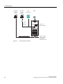
Layout and Block diagram
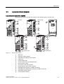
Layout characteristics of the CU240S
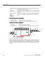
The figure below shows the various interfaces of the different types of Control Units.
&86
&8631
&86'3
Figure 3-1
&86'3)
Control Units CU240S
①
②
③
④
⑤
⑥
⑦
⑧
⑨
⑩
⑪
⑫
⑬
MMC slot
General I/O DIP switches
PROFIBUS DP address DIP switches
Option port
Inverter status LED
Inverter status LEDs and fail-safe LEDs
Bus terminator switch
Terminals for fail-safe functions
RS485 interface via SUB-D connector
PROFIBUS DP interface via SUB-D connector
PROFIBUS DP (PROFIsafe) interface via SUB-D connector
PROFINET interface RJ45
Power Module interface
Control Units CU240S
Operating Instructions, 06/2007 - SW 3.0, A5E00766042B AB
21
Description
3.3 Layout and Block diagram
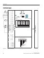
CU240S block diagram
3RZHU0RGXOH
(QFRGHU=
WHUPLQDWLRQ
(QFRGHU%
WHUPLQDWLRQ
(QFRGHU$
WHUPLQDWLRQ
9(QFRGHU
VXSSO\
9(QFRGHU
VXSSO\
$,
9
9
00&
$,
$,
',
',
2SWLRQ3RUW
',
',
89
3&&RQQHFWLRQ.LW
%23
$,
RSWLRQDO
%DVLF2SHUDWRU3DQHO
$,
*HQHUDO,2',3VZLWFKHV
$2
21
$2
37&
37&
',
',
1&
12 '2
&20
2))
12
'2
&20
1&
12 '2
&20
$2
$2
89
$,
9
9
(1&
6XSSO\
',
',
',
Figure 3-2
22
(1&$3
(1&$1
(1&%3
(1&%1
(1&=3
(1&=1
6KLHOG
93
5['7['3
5['7['1
&1753
'*1' CU240S block diagram
Control Units CU240S
Operating Instructions, 06/2007 - SW 3.0, A5E00766042B AB
Description
3.3 Layout and Block diagram
$,
9(QFRGHU
VXSSO\
9(QFRGHU
VXSSO\
(QFRGHU$
WHUPLQDWLRQ
(QFRGHU%
WHUPLQDWLRQ
(QFRGHU=
WHUPLQDWLRQ
%LW
%LW
%LW
%LW
%LW
2))
%LW
9
9
(1&
6XSSO\
$,
9
9
00&
$,
$,
',
2SWLRQ3RUW
',
',
',
89
3&&RQQHFWLRQ.LW
%23
$,
RSWLRQDO
%DVLF2SHUDWRU3DQHO
$,
*HQHUDO,2',3VZLWFKHV
$2
21
$2
37&
37&
',
',
1&
12 '2
&20
2))
12
'2
&20
352),%86$GGUHVV',3VZLWFK%VS$GUHVVH
1&
21
12 12
&20
$2
$2
89
%LW
',
',
',
Figure 3-3
(1&$3
(1&$1
(1&%3
(1&%1
(1&=3
(1&=1
3RZHU0RGXOH
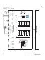
CU240S DP block diagram
6KLHOG
93
89
89
5['7['3
5['7['1
&1753
'*1' CU240S DP block diagram
Control Units CU240S
Operating Instructions, 06/2007 - SW 3.0, A5E00766042B AB
23
Description
3.3 Layout and Block diagram
Figure 3-4
24
)',$
)',%
)',$
)',%
(1&$3
(1&$1
(1&%3
(1&%1
(1&=3
(1&=1
$,
9(QFRGHU
VXSSO\
9(QFRGHU
VXSSO\
(QFRGHU$
WHUPLQDWLRQ
(QFRGHU%
WHUPLQDWLRQ
(QFRGHU=
WHUPLQDWLRQ
%LW
%LW
%LW
%LW
%LW
2))
%LW
9
9
(1&
6XSSO\
$,
9
9
00&
$,
$,
',
2SWLRQ3RUW
',
',
',
)',$
3&&RQQHFWLRQ.LW
%23
$,
RSWLRQDO
%DVLF2SHUDWRU3DQHO
$,
*HQHUDO,2',3VZLWFKHV
$2
21
$2
37&
37&
',
',
1&
12 '2
&20
2))
12
'2
&20
352),%86$GGUHVV',3VZLWFK%VS$GUHVVH
1&
21
12 12
&20
$2
$2
89
%LW
3RZHU0RGXOH
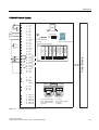
CU240S DP-F block diagram
6KLHOG
93
89
89
5['7['3
5['7['1
&1753
'*1' CU240S DP-F block diagram
Control Units CU240S
Operating Instructions, 06/2007 - SW 3.0, A5E00766042B AB
Description
3.3 Layout and Block diagram
CU240S PN block diagram
(QFRGHU=
WHUPLQDWLRQ
3RZHU0RGXOH
(QFRGHU%
WHUPLQDWLRQ
%23
%DVLF2SHUDWRU3DQHO
(QFRGHU$
WHUPLQDWLRQ
9(QFRGHU
VXSSO\
$,
9(QFRGHU
VXSSO\
9
9
00&
$,
$,
',
2SWLRQ3RUW
',
',
',
89
3&&RQQHFWLRQ.LW
$,
RSWLRQDO
$,
*HQHUDO,2',3VZLWFKHV
$2
21
$2
37&
37&
',
',
1&
'2
12
&20
2))
12
'2
&20
1&
12
12
&20
$2
$2
89
$,
9
9
(1&
6XSSO\
;3
;3
',
',
',
Figure 3-5
(1&$3
(1&$1
(1&%3
(1&%1
(1&=3
(1&=1
7;7UDQVPLW'DWD
7;7UDQVPLW'DWD
5;5HFHLYH'DWD
XQXVHG
XQXVHG
5;5HFHLYH'DWD
XQXVHG
XQXVHG
CU240S PN block diagram
Control Units CU240S
Operating Instructions, 06/2007 - SW 3.0, A5E00766042B AB
25
'HVFULSWLRQ
,QWHUIDFHVRIWKH&RQWURO8QLWV
,QWHUIDFHVRIWKH&RQWURO8QLWV
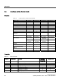
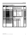
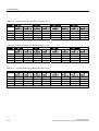
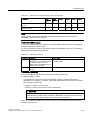
2YHUYLHZ
7DEOH
,QWHUIDFHVRIWKH&RQWURO8QLWV&86
&RQWURO8QLW
&86
&86'3
&86'3)
&8631
'LJLWDO,QSXWV
)DLOVDIHGLJLWDO,QSXWV
'LJLWDO2XWSXWV
$QDORJ,QSXWV
$QDORJ2XWSXWV
37&.7<LQWHUIDFH
[
[
[
[
77/RU+7/
77/RU+7/
77/RU+7/
77/RU+7/
x
[
x
[
x
[
x
[
(QFRGHULQWHUIDFH
([W9
00&LQWHUIDFH
00&VORW
2SWLRQSRUW
6WDUWHURU
%23LQWHUIDFH
6WDUWHURU
%23LQWHUIDFH
6WDUWHURU
%23LQWHUIDFH
%XVLQWHUIDFH
6WDUWHURU
%23LQWHUIDFH
866RQ56
352),%86
352),%86
352),VDIH
352),1(7
68%'
FRQQHFWRU
68%'
FRQQHFWRU
68%'
FRQQHFWRU
5-
352),%86'3',3
VZLWFKHV
[
[
*HQHUDO,2',3VZLWFKHV
[
[
[
[
3RZHUPRGXOHLQWHUIDFH
30,)
[
[
[
[
7HUPLQDOV
[
[
[
[
6WDWXV/('V
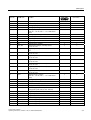
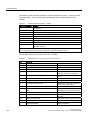
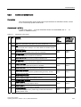
7HUPLQDOV
7DEOH
7HUPLQDO
&RQWUROWHUPLQDOV
'HVLJQDWLRQ
)XQFWLRQ
&86
&86'3
&8631
&86'3)
9287
1RQLVRODWHGRXWSXW9PD[P$
[
[
9287
6XSSO\UHIHUHQFHWHUPLQDO
[
[
$,
$QDORJLQSXWSRVLWLYH
[
[
$,
$QDORJLQSXWQHJDWLYH
[
[
',
'LJLWDOLQSXWLVRODWHG
[
[
',
'LJLWDOLQSXWLVRODWHG
[
[
',
'LJLWDOLQSXWLVRODWHG
[
[
&RQWURO8QLWV&86
2SHUDWLQJ,QVWUXFWLRQV6:$(%$%
Description
3.4 Interfaces of the Control Units
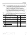
CU240S;
CU240S DP;
CU240S PN
CU240S DP-F
Digital input 3, isolated
x
x
Isolated output +24 V – max. 100 mA
x
x
Analog input 1 positive
x
x
Analog input 1 negative
x
x
Analog output 0 positive
(0/4 mA … 20 mA, 0/2 V … 10 V with 500 Ω
load)
x
x
Analog output 0 negative
x
x
PTC+
Motor temperature sensor (PTC or KTY84-130)
x
x
PTC-
Motor temperature sensor (PTC or KTY84-130)
x
x
16
DI4
Digital input 4, isolated
x
x
17
DI5
Digital input 5, isolated
x
x
18
DO0, NC
Digital output relay 0. normally closed,
0.5 A, 30 V DC
x
x
19
DO0, NO
Digital output relay 0. normally open, 0.5 A, 30 V
DC
x
x
20
DO0, COM
Digital output relay 0. common,
0.5 A, 30 V DC
x
x
21
DO1, NO
Digital output relay 1. normally open,
0.5 A, 30 V DC
x
x
22
DO1, COM
Digital output relay 1. common,
0.5 A, 30 V DC
x
x
23
DO2, NC
Digital output relay 2. normally closed,
0.5 A, 30 V DC
x
x
24
DO2, NO
Digital output relay 2. normally open,
0.5 A, 30 V DC
x
x
25
DO2, COM
Digital output relay 2. common,
0.5 A, 30 V DC
x
x
26
AO1+
Analog output 1 positive
(0/4 mA … 20 mA, 0/2 V … 10 V with 500 Ω
load)
x
x
27
AO1-
Analog output 1 negative
x
x
28
U0V OUT
Supply reference (terminal 9)
x
x
31
+24V IN
external 24 V input supply
x
x
32
0V IN
Supply reference (terminal 31)
x
x
33
ENC+ SUPPLY
Power supply for encoder (5 V or 24 V to be
configured by DIP switch, max. 300 mA)
x
x
40
DI6
Digital input 7, isolated
x
--
41
DI7
Digital input 8, isolated
x
--
42
DI8
Digital input 9, isolated
x
--
60
FDI0A
Fail-safe Digital Input 0A
--
x
61
FDI0B
Fail-safe Digital Input 0B
--
x
63
FDI1A
Fail-safe Digital Input 1A
--
x
64
FDI1B
Fail-safe Digital Input 1B
--
x
Terminal
Designation
8
DI3
9
U24V OUT
10
AI1+
11
AI1-
12
AO0+
13
AO0-
14
15
Function
Control Units CU240S
Operating Instructions, 06/2007 - SW 3.0, A5E00766042B AB
27
Description
3.4 Interfaces of the Control Units
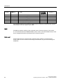
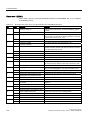
Terminal
CU240S;
CU240S DP;
CU240S PN
CU240S DP-F
Channel A non-inverting input
x
x
Channel A inverting input
x
x
ENC BP
Channel B non-inverting input
x
x
ENC BN
Channel B inverting input
x
x
ENC ZP
Channel 0 (zero) non-inverting input
x
x
ENC ZN
Channel 0 (zero) inverting input
x
x
Designation
Function
70
ENC AP
71
ENC AN
72
73
74
75
The control terminals have a maximum tighten torque of 0.25 Nm (2.2 lbf.in) and a nominal
cross section of 1.5 mm2 (AWG 14) for cable.
MMC
The MMC provides the ability to store parameter sets or firmware versions of an inverter.
It is recommended that the SINAMICS-MMC (order number: 6SL3254-0AM00-0AA0) is used
for the storage and transfer of parameter sets or firmware versions.
Option port
Via the Option port a PC (using the PC Connection Kit) or a BOP is connected to the
inverter. With a PC the inverter can be easily parameterized using the commissioning tool
STARTER.
28
Control Units CU240S
Operating Instructions, 06/2007 - SW 3.0, A5E00766042B AB
Description
3.5 Factory Settings of the CU240S Control Units
3.5
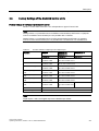
Factory Settings of the CU240S Control Units
Factory settings for command and setpoint source
P0700 = 0 is the same as P0700 = 2 or 6 dependent on type of Control Unit.
Note
Setting P0700 = 6 (command source via fieldbus communication) and P1000 = 6 (setpoint
source via fieldbus communication) are not possible with a CU240S.
Setting P0700 = 5 (command source via USS communication) and P1000 = 5 (setpoint
source via USS communication) are not possible with a CU240S DP or a CU240S DP-F.
Table 3-3
Function selection of digital input and digital output
Function
CU240S
CU240S DP;
CU240S PN
CU240S DP-F
P0700 = 2
P0700 = 6
P0700 = 6
ON/OFF1
P0701 = 1
Function of DI0
r2090.00
Bit 0 from control word 1
Reverse
P0702 = 12
Function of DI1
r2090.11
Bit 11 from control word 1
Fault acknowledge
P0703 = 9
Function of DI2
r2090.07
Bit 7 from control word 1
Fixed frequency selector
bit0
P0704 = 15
Function of DI3
r2091.00
Bit 0 from control word 2
Fixed frequency selector
bit1
P0705 = 16
Function of DI4
r2091.01
Bit 1 from control word 2
Fixed frequency selector
bit2
P0706 = 17
Function of DI5
r2091.02
Bit 2 from control word 2
Fixed frequency selector
bit3
P0707 = 18
Function of DI6
r2091.03
Bit 3 from control word
2
Drive fault active
P0731 = 52.3, Function of DO0
Drive warning active
P0732 = 52.7, Function of DO1
---
Note
Digital inputs 7 and 8 and Digital output 2 are disabled per default.
Control Units CU240S
Operating Instructions, 06/2007 - SW 3.0, A5E00766042B AB
29
Description
3.5 Factory Settings of the CU240S Control Units
Table 3-4
BICO Command Parameter
Function
CU240S
CU240S DP; CU240S DP-F;
CU240S PN
P0700 = 2
P0700 = 6
ON/OFF1 / ON/OFF1
P0840 = 722.0
Function of DI0
P0840 = 2090.0
Bit 0 from control word 1
ON reverse/OFF1
not active with default settings
P0842 = 0.0
P0842 = 0.0
First OFF2 source: Coast stop
P0844 = 1.0
P0844 = 2090.1
Second OFF2 source: Coast
stop
P0845 = 19.1
P0845 = 19.1
First OFF3 source: Quick stop
P0848 = 1.0
P0848 = 2090.2
Second OFF3 source: Quick
stop
P0849 = 1.0
P0849 = 1.0
Pulse enable
P0852 = 1.0
P0852 = 2090.3
Table 3-5
BICO Command Sources for fixed frequencies
Function
CU240S
CU240S DP; CU240S DP-F;
CU240S PN
P0700 = 2
P0700 = 6
Fixed freq. selection Bit 0
P1020 = 722.3
Function of DI3
P1020 = 722.3
Function of DI3
Fixed freq. selection Bit 1
P1021 = 722.4
Function of DI4
P1021 = 722.4
Function of DI4
Fixed freq. selection Bit 2
P1022 = 722.5
Function of DI5
P1022 = 722.5
Function of DI5
Fixed freq. selection Bit 3
P1023 = 722.6
Function of DI6
P1023 = 722.6
(0.0 for CU240S DP-F)
Table 3-6
Faults, alarms, monitoring
Function
30
CU240S
CU240S DP; CU240S DP-F;
CU240S PN
P0700 = 2
P0700 = 6
Fault acknowledgement - first
source
P2103 = 722.2
Function of DI2
P2103 = 722.2
Function of DI2
Fault acknowledgement second source
P2104 = 0.0
P2104 = 2090.7
Fault acknowledge
External fault
P2106 = 1.0
P2106 = 1.0
Control Units CU240S
Operating Instructions, 06/2007 - SW 3.0, A5E00766042B AB
Description
3.5 Factory Settings of the CU240S Control Units
Factory settings for setpoint source
Source
Frequency setpoint
CU240S
CU240S DP, CU240S DP-F; CU240S PN
P1000 = 2
P1000 = 6
Analog setpoint (P0754 [%])
Fieldbus (P2050.1 [Hex])
Control Units CU240S
Operating Instructions, 06/2007 - SW 3.0, A5E00766042B AB
31
Installing/Mounting
4
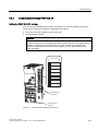
Installing the Control Unit
The CU controls the functions of the PM. The CU cannot be used without a PM, also the PM
cannot be used without a CU.
WARNING
An inverter can be switched on unintentionally if the installation is not performed correctly.
The inverter must be started-up by personnel who are qualified and trained in installing
systems of this type.
4.1
Fitting the CU to the PM
Description
The Control Unit is snapped on to the Power Module as shown in the figure below. To
disconnect the CU push the release button on top of the PM.
The process of fitting the Control Unit to the Power Module is the same technique
independent from the type of G120 control unit or G120 power module.
Control Units CU240S
Operating Instructions, 06/2007 - SW 3.0, A5E00766042B AB
33
Installing/Mounting
4.1 Fitting the CU to the PM
Figure 4-1
Fitting the control unit to the power module
24 V power supply
Normally the CU is supplied with 24 V from Power Module. But it is also possible to use an
external DC 24 V supply (20.4 V … 28.8 V, 0.5 A). It must be connected to the Control Unit
terminals 31 (+ 24 V In) and 32 (0 V In). Some reasons for using an external 24 V power
supply are:
● The PROFIBUS DP interface is required to communicate with the Control Unit when the
Power Module mains power is not present
● Supply for 24 V encoder
CAUTION
Care must be taken to ensure that the 24 V DC power is connected correctly or damage
to the Control Unit may occur.
Max. cable length on 24 V DC supply and I/O cables connected to CU must not exceed
10 m.
Use of unscreened cables is possible, however we recommend the use of screened
cables, in order to fulfill the EMC requirements for the CE marking and fail-safe products
(CU240S DP-F).
Note
If the CU is externally powered with 24 V DC but the power module is disconnected from
the mains supply, the faults F0001 … F0028 are not generated.
34
Control Units CU240S
Operating Instructions, 06/2007 - SW 3.0, A5E00766042B AB
Installing/Mounting
4.2 Connecting a CU240S via Terminals
4.2
Connecting a CU240S via Terminals
Description
To have access to the control terminals, the terminal cover must be removed, as shown in
the figure below. The control terminals have a maximum tighting torque of 0.25 Nm
(2.2 lbf.in) and a nominal cable cross section of 1.5 mm2.
Figure 4-2
Removing the Control Unit terminal cover
The terminals of the CU240 control units are combined to terminal blocks. They can be
detached from the control unit, as shown in the figure below.This allows the control units to
be swapped out for another of the same type without the need for rewiring.
Control Units CU240S
Operating Instructions, 06/2007 - SW 3.0, A5E00766042B AB
35
Installing/Mounting
4.2 Connecting a CU240S via Terminals
Figure 4-3
Removing the two-part connectors with a CU240S DP as example
After all the wiring of the control unit is completed - ensure that the terminal cover is
replaced.
Terminal wiring examples for the Control Unit CU240S
Note
To control the CU240S DP, CU240S DP-F or CU240S PN via terminals is also possible, but
in this case the parameter settings for command and setpoint source have to be changed.
In this section examples of controlling a SINAMICS G120 inverter with a CU240S via
terminals are shown.
CAUTION
Use of unscreened cables is possible, however we recommend the use of screened cables
in order to fulfill the EMC requirements for the CE marking and fail-safe products (CU240S
DP-F).
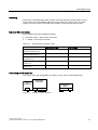
● Control with the default settings
● Frequency setpoint and an additional setpoint via terminals
(AI0 and AI1 used as voltage inputs)
● Frequency setpoint and an additional setpoint via terminals
(AI0 and AI1 used as current inputs)
36
Control Units CU240S
Operating Instructions, 06/2007 - SW 3.0, A5E00766042B AB
Installing/Mounting
4.2 Connecting a CU240S via Terminals
Control with the default settings
When shipped from the factory the G120 inverter (Control Unit and Power Module) must not
be operated before the values depending on the specific PM are read into the CU.
This can be done via:
● Downloading a valid parameter set (by MMC, STARTER, or BOP)
● Quick commissioning
● A factory reset
To operate the inverter with the basic settings (e.g. after factory reset, without additional
parameterization or DIP switch setting), the following conditions have to be fulfilled:
● The rated current of the inverter is at least as great as the rated current of the motor.
● The power range of the inverter matches the power range of the motor.
● The controlled motor is a 4-pole motor (best Siemens 1LA7).
● The rated motor frequency is 50 Hz, power dimension unit is kW.
Control settings
Digital and analog inputs for commands and setpoints are parameterized for a cabling as
shown in the block diagram of the CU240S in the operating instructions. Furthermore the
state of the inverter is monitored via digital and analog outputs.
4.2.1
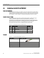
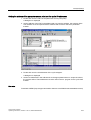
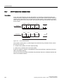
Setting Frequency Setpoints via the DIP Switches
Setting Frequency Setpoints via the DIP Switches
The general I/O DIP switches 1 and 2 are used to configure the analog inputs (AI). For using
AI0 and AI1 as voltage inputs set DIP switches 1 and 2 to OFF position.
Table 4-1
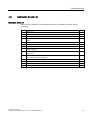
Settings of the AI DIP switches
DIP switch
1
2
1
2
AI0 and AI1 as current input
Control Units CU240S
Operating Instructions, 06/2007 - SW 3.0, A5E00766042B AB
-10 V …
+ 10 V
2
1
$,
$,
1
AI0 and AI1 as voltage input
$,
OFF
$,
ON
2
-10 V …
+ 10 V
0 mA …
20 mA
0 mA …
20 mA
37
Installing/Mounting
4.2 Connecting a CU240S via Terminals
Parameter settings
For failure-free operation, the parameter P0756 must be set according to the DIP switches.
The respective parameters and values are given below.
Table 4-2
Parameter settings according to the AI DIP switches
Parameter
Description
P0003 = 3
User access level*
3: Expert: For expert use only
P1000[0] = 2
Selection of frequency setpoint*
2: Analog setpoint (Default for CU240S)
Setting
0 mA … 20 mA
P0756[0] = 2
Type of AI
Sets analog input 0 (AI0) to current input = DIP on left (DIP 1)
P0756[1] = 2
Type of AI
Sets analog input 1 (AI1) to current input = DIP on right (DIP 2)
4 mA … 20 mA
P0757[0] = 4
Value x1 of AI scaling
Sets analog input 0 (AI0) to a minimum of 4 mA.
P0761[0] = 4
Width of AI dead band
Sets the dead band width of analog input 0 (AI0).
P0757[1] = 4
Value x1 of AI scaling
Sets analog input 1 (AI1) to a minimum of 4 mA.
P0761[1] = 4
Width of AI dead band
Sets the dead band width of analog input 1 (AI1).
Note
If you use just one analog input, you only need to change the respective index for the
specific analog input.
Frequency setpoint and an additional setpoint via terminals
AI0 and AI1 used as voltage inputs
This type of control wiring allows a main frequency setpoint and an additional setpoint to be
established, using potentiometers on analog inputs AI0 and AI1.
The following figure illustrates the wiring that is necessary to accomplish this functionality.
!N˖
9
9
$,
$,
DIP switch and parameter settings
The general I/O DIP switches 1 and 2 are used to configure the analog inputs (AI). For
using AI0 and AI1 as voltage inputs set DIP switches 1 and 2 to OFF position.
For failure-free operation, the parameter P0756 must be set accordingly.
$,
$,
See also
Setting Frequency Setpoints via the DIP Switches (Page 37)
38
Control Units CU240S
Operating Instructions, 06/2007 - SW 3.0, A5E00766042B AB
Installing/Mounting
4.2 Connecting a CU240S via Terminals
Frequency setpoint and an additional setpoint via terminals
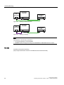
AI0 and AI1 used as current inputs
This type of control wiring allows a main frequency setpoint and an additional setpoint to be
established, for example from a PLC.
The following figure illustrates the wiring that is necessary to accomplish this functionality.
P$
RU
P$
P$
RU
P$
DIP switch and parameter settings
$,
$,
The general I/O DIP switches 1 and 2 are used to configure the analog inputs (AI).
For using AI0 and AI1 as voltage inputs set DIP switches 1 and 2 to OFF position.
For failure-free operation, the parameter P0756 must be set accordingly.
$,
$,
See also
Setting Frequency Setpoints via the DIP Switches (Page 37)
Control Units CU240S
Operating Instructions, 06/2007 - SW 3.0, A5E00766042B AB
39
Installing/Mounting
4.3 Connecting a CU240S via USS on RS485
4.3
Connecting a CU240S via USS on RS485
Socket
The Control Units CU240S have a 9-pin female sub-D socket for connecting the inverter via
an RS485 interface.
Table 4-3
PIN assignment of the 9-pin sub-D socket
Pin
Designation
Description
1
-
Unused
2
-
Unused
RS485P
Receive- and transmit signal (+)
-
Unused
3
4
5
Connector
0V
Ground reference
6
-
Unused
7
-
Unused
8
RS485N
Receive- and transmit signal (-)
9
-
Unused
X
Screen (casing) Potential equilisation
A standard 9 pin sub-D connector can be used for USS connection via RS485.
Table 4-4
Technical data of standard 9-pin sub-D connector for RS485
Standard 9 pin sub D connector
PG socket
Bus termination
No
Max. baud rate
115200 Baud
Outgoing cable unit
180°
The RS485 termination can be activated via switches on the housing of the SINAMICS
G120.
The bus termination switch is illustrated in figure "Control Units CU 240S" in section "Layout
and Block Diagram".
40
Control Units CU240S
Operating Instructions, 06/2007 - SW 3.0, A5E00766042B AB
Installing/Mounting
4.4 Connecting a CU240S DP or CU240S DP-F via PROFIBUS DP
4.4
Connecting a CU240S DP or CU240S DP-F via PROFIBUS DP
Description
The function of the PROFIBUS DP interface is to provide a PROFIBUS DP-based link
between inverters of the SINAMICS G120 product range and higher-level automation
systems e.g. SIMATIC S7.
4.4.1
Connecting the PROFIBUS DP
Connecting the Inverter to the PROFIBUS DP network
The inverter is to be connected to the PROFIBUS DP network via a sub-D socket on the
CU240S DP or CU240S DP-F. The pins of the socket are short-circuit-proof and isolated.
Table 4-5
PIN assignment of the 9-pin sub-D socket
Pin
Designation
Description
1
Shield
Ground connection
2
U0V
Isolated and user supply reference
3
RxD/TxD-P
Receive/send data P (B/B')
RS485
4
CNTR-P
Control Signal
TTL
5
DGND
PROFIBUS data reference potential (C/C')
6
VP
Supply voltage positive
7
U24V
Isolated user supply +24 V @ 100 mA
8
RxD/TxD-N
Receive/send data N (A/A')
9
-
Not assigned
Case
Cable shield
Cable shield
Range
5 V ± 10 %
RS485
External 24 V supply
If the PROFIBUS DP interface is required to communicate with the Control Unit when the
Power Module mains power is not present, a 24 V supply must be connected to the Control
Unit terminals 31 (+ 24 V In) and 32 (0 V In).
Maximum cable length
The PROFIBUS system can handle up to 126 stations. To run all these stations the
PROFIBUS system is divided into segments. All segments have to be connected via
repeater. The maximum number of stations on any segment must not exceed 32.
The maximum cable lengths are dependent on the baud rate (transmission speed). The
maximum cable lengths specified in the table below can be guaranteed only with PROFIBUS
bus cables (for example, Siemens PROFIBUS bus cable, order number 6XV1830-0EH10).
Control Units CU240S
Operating Instructions, 06/2007 - SW 3.0, A5E00766042B AB
41
Installing/Mounting
4.4 Connecting a CU240S DP or CU240S DP-F via PROFIBUS DP
Table 4-6
Permissible cable length for one segment
Baud rate
Max. cable lengths for one segment
9.6 kbaud … 187.5 kbaud
1000 m (3280 ft)*
500 kbaud
400 m (1312 ft)*
1.5 Mbaud
200 m (656 ft)*
3 Mbaud … 12 Mbaud
100 m (328 ft)*
∗ Repeaters can be installed to increase the length of a segment.
Cable installation rules
During installation the bus cable must not be:
● twisted
● stretched or
● compressed.
Supplementary constraints as regards electromagnetic compatibility must also be observed.
Bus connector
To connect the PROFIBUS cable to the PROFIBUS DP interface, a bus connector of one of
the types described in the following table is recommended.
Table 4-7
Recommended PROFIBUS connectors
Order Number
6GK1 500-0FC00
6GK1 500-0EA02
PG socket
No
No
Max. baud rate
12 Mbaud
12 Mbaud
Terminating resistor
On/Off switch
On/Off switch
Outgoing cable unit
180°
180°
Interfaces
PROFIBUS nodes
9-pin sub D socket
9-pin sub D socket
PROFIBUS bus cable
4 modular terminals for wires up
to 1.5 mm2
4 modular terminals for wires up
to 1.5 mm2
Connectable PROFIBUS cable
diameter
8 ± 0.5 mm
8 ± 0.5 mm
Note
We recommend only these two connectors since they can be used without difficulty for all
SINAMICS G120 models and are completely compatible in terms of outgoing cable unit
angle.
42
Control Units CU240S
Operating Instructions, 06/2007 - SW 3.0, A5E00766042B AB
Installing/Mounting
4.4 Connecting a CU240S DP or CU240S DP-F via PROFIBUS DP
PROFIBUS terminator
Each bus segment must have a resistor network at both ends as shown in the figure below.
3/&FRQQHFWRU
WHUPLQDWHG
5
5
RQ
5
RQ
RII
RQ
RII
RII
$ % $ %
$ % $ %
)URQWYLHZLQYHUWHU
%XVWHUPLQDWLRQ
VZLWFKRQ
WKHFRQQHFWRU
5
RQ
RII
$ % $ %
%XV7HUPLQDWRUVZLWFKRQ
WKHKRXVLQJ
6LGHYLHZLQYHUWHU
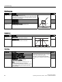
Figure 4-4
PROFIBUS network with bus termination
You have two options to terminate the bus connection:
● Terminator switch on the recommended PROFIBUS connector
The switches of the bus terminator provides both the 220 Ω termination and the 390 Ω
biasing. The 390 Ω biasing maintains the potential difference between the signals in the
PROFIBUS network cables.
%XV
WHUPLQDWRU
VZLWFK
8S %XVWHUPLQDWLRQ21
'RZQ %XVWHUPLQDWLRQ2))
Figure 4-5
•
PROFIBUS DP bus termination switch
Terminator switch on the housing of the SINAMICS G120
(see section "Layout and Block diagram")
Control Units CU240S
Operating Instructions, 06/2007 - SW 3.0, A5E00766042B AB
43
Installing/Mounting
4.4 Connecting a CU240S DP or CU240S DP-F via PROFIBUS DP
Caution
Never use both ways to terminate the bus connection. This can interfere the communication.
WARNING
It must be ensured that any node, where the biasing components of the bus are connected,
is powered at all times in which the bus is in operation.
Removing a bus connector
You can remove the bus connector with looped-through bus cable from the PROFIBUS DP
interface at any time without interrupting the data exchange on the bus. Only the final node
must be terminated.
R
R
on
off
on
off
A1 B1 A2 B2
A1 B1 A2 B2
Figure 4-6
Removing a bus connector
4.4.2
Screening the bus cable and EMC precautions
Description
The following EMC-related precautions must be taken to ensure interference-free
PROFIBUS DP operation.
Screening
The screen of the PROFIBUS DP cable must be connected in the bus connector. Additional
screening is provided using a screen clamp on the bus cable screen which must make 360°
contact with the protective earth. The solid copper core must not be scored when the
insulation is removed from the core ends. You must also ensure that the screen of each bus
cable is connected to protective earth at both the cabinet entry point and in the inverter
housing.
44
Control Units CU240S
Operating Instructions, 06/2007 - SW 3.0, A5E00766042B AB
Installing/Mounting
4.4 Connecting a CU240S DP or CU240S DP-F via PROFIBUS DP
Note
The bus cables must be internally twisted and screened, and installed separately from power
cables with a minimum distance 20 cm (7.8 inches). The braided screen and underlying
laminated foil screen (if applicable) must be connected in a 360°, positive connection at both
ends, that is, the screen on the bus cable between two inverters must be connected to the
inverter housing at both ends. The same applies to the screen of the bus cable between the
PROFIBUS DP master and inverter.
Crossovers between bus and power cables must be laid at an angle of 90°.
Equipotential bonding
Differences in potential (for example, due to different mains supplies) between the inverters
and the PROFIBUS DP master must be avoided.
● Recommended equipotential bonding cables:
– 16 mm2 Cu for equipotential bonding cables up to 200 m long
– 25 mm2 Cu for equipotential bonding cables of over 200 m long.
● Equipotential bonding cables must be routed as close as possible to signal leads; this
means that the area between the bonding conductor and signal lead is as small as
possible.
● Equipotential bonding cables must be contacted in a 360° connection with the earth
electrode/PE conductor.
Control Units CU240S
Operating Instructions, 06/2007 - SW 3.0, A5E00766042B AB
45
Installing/Mounting
4.5 Connecting a CU240S PN via PROFINET
4.5
Connecting a CU240S PN via PROFINET
Control Unit CU240S PN
The PROFINET functionality is provided by Control Unit CU240S PN. The CU240S PN is
equipped with a two port Ethernet switch. Connection to optical nets is achieved by using
switches with both electrical and optical ports, the drive is then connected to an electrical
port. Therefore, no power supply for an external electrical/optical inverter is provided.
Industrial Ethernet FC RJ45
The two Ethernet ports are carried out as RJ45 female Sockets. Outlets with straight
direction are placed on bottom of control unit, with support for secure collar.
The assembly of the SIMATIC NET Industrial Ethernet FastConnect RF45 Plug 180 is
described in the product information "Assembly Instructions for SIMATIC NET Industrial
Ethernet FastConnect RJ45 Plug". For downloading this document, refer to:
http://support.automation.siemens.com/WW/view/en/23175326/130000
Table 4-8
PIN assignment of the RJ45 female socket
Pin
Signal
Function
Core color
1
TX+
Transmission data +
Yellow
2
TX
Transmission data -
Orange
3
RX+
Receiver data +
White
4
-
5
-
6
RX-
Receiver data -
blue
Connector
Table 4-9
46
Recommended PROFINET connectors
Order Number
6GK1901-1BB10-2Ax0
Label
Industrial Ethernet FC RJ45 Plug 180
Max. baud rate
100 Mbit/s; Cat5e
Outgoing cable unit
180°
Degree of protection
IP20
Operating temperature
-20 °C … +70 °C
Control Units CU240S
Operating Instructions, 06/2007 - SW 3.0, A5E00766042B AB
Installing/Mounting
4.5 Connecting a CU240S PN via PROFINET
Screening
The screen of the PROFINET cable must be connected with the protective earth, using a
screen clamp on the PROFINET cable which must make 360° contact earth. The solid
copper core must not be scored when the insulation is removed from the core ends.
Industrial Ethernet Cables
The CU240S PN provides all Ethernet-cables.
● Crossover-cables = Peer to peer connection
● 1:1 cables = Connection via switch
Table 4-10
Recommended PROFINET cables
Max. Cable Length
Order Number
Industrial Ethernet FC TP
Standard Cable GP 2 x 2
100 m
6XV1840-2AH10
Industrial Ethernet FC TP
Flexible Cable GP 2 x 2
85 m
6XV1870–2B
Industrial Ethernet FC Trailing
Cable GP 2 x 2
85 m
6XV1870–2D
Industrial Ethernet FC Trailing
Cable 2 x 2
Industrial Ethernet FC Marine
Cable 2 x 2
6XV1840–3AH10
85 m
6XV1840–4AH10
Connecting the IO supervisor
You can go online with STARTER in a number of ways, which are illustrated below:
(6
67$57(5
31
Figure 4-7
352),1(7
&RQWUROOHU
6,1$0,&6
*
3%
352),1(7
352),1(7 866
Topology 1: direct connection
Control Units CU240S
Operating Instructions, 06/2007 - SW 3.0, A5E00766042B AB
47
Installing/Mounting
4.5 Connecting a CU240S PN via PROFINET
(6
67$57(5
31
Figure 4-8
(6
67$57(5
3%
Figure 4-9
352),1(7
&RQWUROOHU
6,1$0,&6
*
3%
352),1(7
352),1(7 866
Topology 2: direct connection
352),1(7
&RQWUROOHU
6,1$0,&6
*
3%
352),1(7
352),1(7 866
Topology 3: Routing
Note
Pay attention to the following restrictions:
• A ring-type topology is not permissible.
• SINAMICS does not support routing from PROFIBUS to PROFINET and vice versa.
See also
Assembly Instructions RJ45 Plug
(http://support.automation.siemens.com/WW/view/en/23175326/130000)
48
Control Units CU240S
Operating Instructions, 06/2007 - SW 3.0, A5E00766042B AB
Installing/Mounting
4.6 Installation Check List
4.6
Installation Check List
Installation check list
Before power is applied to the inverter/motor system, the following checks should be
performed:
Check that:
1
The environmental conditions conform to the inverter/motor specifications
2
The inverter and the motor are securely mounted
3
The inverter and motor are correctly installed with adequate cooling provision
4
The motor and the application/equipment are ready to start, i.e. safe state - motor can
rotate
5
The inverter is correctly earthed/grounded
6
The input power (supply) voltage matches the inverter's nominal input voltage
7
The input power (mains) fuses are the correct type and installed correctly
8
The motor connections are connected to ensure the correct direction of rotation of the
motor at start-up
9
The motor and mains connections are connected and tightened to the required
specification
10
The motor connections are not reversed - the motor will start but serious damage may
occur to the connected equipment
11
The motor cable is routed away from other cables
12
The control connections are connected and tightened to the required specification
13
No tools or other objects that can cause damage to the system are present
14
The inverter is the only power source to the motor
Control Units CU240S
Operating Instructions, 06/2007 - SW 3.0, A5E00766042B AB
✓
49
Commissioning
5
Overview
A G120 inverter is composed of the Power Module and the Control Unit. After snapping the
Control Unit on to the Power Module for the first time, the devices must identify each other.
To indicate, that the Power Module and the Control Unit are not yet identified, F0395 is
displayed. For further information to the message F0395, refer to section "Message F00395".
The G120 inverter provides two options for commissioning:
● Single commissioning
One inverter is parameterized for commissioning with an individual parameter set. Usually,
you use the STARTER or BOP for single commissioning.
● Series commissioning
Several inverters are parameterized for commissioning via download of a complete
parameter set. Usually, you use the MMC for series commissioning.
Note
We recommend commissioning via STARTER. The commissioning process using STARTER
is driven by dialog boxes and will not be interpreted in this manual. This manual describes
the parameter related commissioning via BOP.
Interfaces
The G120 inverter provides different communication interfaces. The following figure provides
you an overview:
Control Units CU240S
Operating Instructions, 06/2007 - SW 3.0, A5E00766042B AB
51
Commissioning
4.6 Installation Check List
67$57(5
YLD68%'
FDEOH
67$57(5
YLD3&
FRQQHFWLRQ
NLW
%23
GLUHFWO\ILWWHG
3&
FRQQHFWLRQ
NLW
56!56LQYHUWHU
Figure 5-1
52
00&
2SWLRQ3RUW
866RQ56
'W\SHFRQQHFWRU
Ⴠ866RQ56
Ⴠ352),%86
Ⴠ352),1(75-
Communications interfaces
Control Units CU240S
Operating Instructions, 06/2007 - SW 3.0, A5E00766042B AB
Commissioning
5.1 Single Commissioning
5.1
Single Commissioning
Overview
For single commissioning, you set the parameter of the inverter manually. You use BOP
(Basic Operator Panel) or STARTER (Commissioning software via PC) for commissioning.
Note
We recommend commissioning via STARTER. The commissioning process using STARTER
is driven by dialog boxes and will not be interpreted in this manual. This manual describes
the parameter related commissioning via BOP.
Settings of commissioning
Commissioning the G120 inverter comprises different settings and kinds of single
commissioning. The following list provides you an overview:
● Basic commissioning
– Quick commissioning
– Motor data identification
– Speed control optimization
● Further settings for commissioning
– Calculating the motor/control data
– Commissioning the application
– Reset parameters to factory settings
– Commissioning the fail-safe functions (only in fail-safe applications)
For detailed information to the settings of single commissioning, refer to the section
"Commissioning with BOP".
Factory settings
The inverter is delivered with identical factory settings for all CU240S Control Units; except
the following settings:
● Command source
● Setpoint source
● Values depending on the Power Module
The factory settings of the Power Modules are specific for the type of PM.
For details to the factory settings, refer to the Parameter Manual.
Note
After the first power on, the fault F0395 will appear. This means, no commission is until now
implemented. After confirming the message, you can proceed commissioning.
Control Units CU240S
Operating Instructions, 06/2007 - SW 3.0, A5E00766042B AB
53
Commissioning
5.2 Series Commissioning
5.2
Series Commissioning
5.2.1
Common Information to Series commissioning
Description
Series commissioning means transferring the parameter set from one inverter into a number
of other inverters. This provides fast commissioning for identical applications, e. g. series
machines or group inverters.
Components for series commissioning
Commissioning the G120 inverter can be done in different ways. The following list provides
you an overview:
● Series commissioning with MMC
● Series commissioning with BOP
● Series commissioning with STARTER
For detailed information to series commissioning, refer to the chapters "Commissioning with
BOP", Commissioning with MMC", and "Commissioning with STARTER".
Order of series commissioning
The series commissioning is divided into the following steps:
● Creating a valid parameter set
● Uploading this parameter set
● Downloading of the uploaded parameter set into the next inverter
An appropriate parameter set can be created by parameterizing an inverter via BOP or
STARTER.
CAUTION
Parameter download between different types of Control Units and of different firmware
versions is not recommended.
It is possible to download parameter sets from different Control Unit types, however, as the
parameter sets might differ, the user is fully responsible for the consistency of the
downloaded parameter set.
Therefore, the customer has to confirm his responsibility in case of an automatic download
by acknowledging F0395.
During download of a parameter set from an MMC to the EEPROM of the Control Unit
CU240S (e.g. during serial commissioning) you have to note that the LEDs are flashing
correctly. If the Control Unit CU240S is in a fault state, the LEDs indicate this fault state
with higher priority than the download. It is not sure that the parameter set is downloaded
correctly.
54
Control Units CU240S
Operating Instructions, 06/2007 - SW 3.0, A5E00766042B AB
Commissioning
5.2 Series Commissioning
WARNING
For series commissioning, all of the communication interfaces as well as also the digital
and analog interfaces are re-initialized. This results in a brief communications failure or
causes the digital outputs to switch.
Potentially hazardous loads must be carefully secured before starting a series
commissioning.
Potentially hazardous loads can be secured as follows before starting series
commissioning:
• Lower the load to the floor, or
• Clamp the load using the motor holding brake.
Note
Upload
Before the upload starts, the parameters will be copied from RAM to EEPROM
Manual and automatic download
With a manual download all necessary parameters excluding the fail-safe parameters (only
with CUs with fail-safe functions) are downloaded into the inverter. How to perform a manual
download is described in the following section.
With an automatic download even the fail-safe parameters are downloaded into the inverter.
An automatic download can only be performed with an MMC.
An automatic download can be performed at Start-up or by swapping an inverter component
(CU or PM), details are described in the following sections and in the chapter "Operation" of
this manual.
Note
Restrictions to be considered when performing upload and download:
• Only the parameter set stored in the EEPROM of the inverter is uploaded.
• Fail-safe parameters cannot be uploaded via BOP or STARTER.
• Once the upload or download procedure has started, it should not be interrupted.
• Parameter download from a standard CUs to a CUs with fail-safe functions and vice
versa is not possible.
• During the up or download all LEDs are flashing (the "BF" LED is not relevant). After
finishing that process successfully the "RDY" LED is on.
• During the upload process any data already held by the BOP is overwritten.
• If the download fails, the inverter will not function correctly and the "SF" LED (red) is on.
– Possible fault messages in case of download failure with BOP
F0051, F0055, F0056, F0057 or F0058
– Possible fault messages in case of download failure with MMC
F0051, F0061, F0062 or F0063
Control Units CU240S
Operating Instructions, 06/2007 - SW 3.0, A5E00766042B AB
55
Commissioning
5.2 Series Commissioning
NOTICE
After upload and download of parameters between differing Control Units, the parameter
settings must be checked.
Parameter download from a different CU might fail with F0063 if parameters cannot be
downloaded (Check P949 for the (first) parameter number which cannot be downloaded).
If F0061 or F0063 occurs during startup it cannot be cleard except via a power cycle.
5.2.2
Upload and Download of Parameter Sets
Upload of parameter sets
With an upload, a parameter set can be saved in one of the following devices:
● PC (via STARTER)
● MMC
● BOP
Note
The file format for the MMC is FAT. Any other format, such as FAT32 or NTFS are not
compatible with uploading and downloading parameter sets from the inverter.
Formatting can be accomplished using the DOS command line as follows:
C:\>format volume /FS:FAT - where volume has to be replaced by the name of the MMC
drive, for example A.
Please keep in mind that formatting will delete all the contents of the MMC.
An upload can be triggered via
● PROFIBUS
● BOP
● STARTER
A detailed description is given in "Series Commissioning" in the commissioning section.
Download of parameter sets
In the case of a parameter download it is important to distinguish between the following
possibilities:
● Manual download
● Automatic download.
56
Control Units CU240S
Operating Instructions, 06/2007 - SW 3.0, A5E00766042B AB
Commissioning
5.2 Series Commissioning
CAUTION
Parameter download between different types of control units and of different firmware
versions is not recommended.
Basically, it is possible to download parameter sets off different CU types, however, as
the parameter sets might differ, the user is fully responsible for the consistency of the
downloaded parameter set.
Therefore, the user has to take the responsibility in case of an automatic download by
acknowledging F0395.
During download of a parameter set from a MMC to the EEPROM of the Control Unit
CU240S (e.g. during serial commissioning) you have to note that the LEDs are flashing
correctly. If the Control Unit CU240S is in a fault state, the LEDs indicate this fault state
with higher priority than the download. It is not sure that the parameter set is
downloaded correctly.
Manual download
A manual download can be performed similar to an upload via
● PC (STARTER)
● MMC
● BOP
It can be triggered like upload via
● PROFIBUS
● BOP
● STARTER
With a manual download a parameter set without the fail-safe parameters is downloaded
from one of the above mentioned devices into the inverter.
The manual download depends as follows on the settings of P8458.
Table 5-1
P8458 settings after a manual parameter download
P8458 setting in CU
EEPROM
P8458 setting on
download device
P8458 setting after
download
Remark
0
0
0
---
0
1
1
---
0
2
2
---
1
0
0
---
1
1
1
---
1
2
2
---
2
0
0
---
2
1
1
---
2
2
2
---
A detailed description is given in "Series Commissioning" in the commissioning section.
Control Units CU240S
Operating Instructions, 06/2007 - SW 3.0, A5E00766042B AB
57
Commissioning
5.2 Series Commissioning
Automatic download
An automatic download needs a MMC to be performed. It is not possible to perform an
automatic download from a PC or from the BOP.
The automatic download runs as follows according to the settings in P8458 after power cycle
or a after a swap (see "Start-up behavior" in this section).
Table 5-2
P8458 settings after an automatic parameter download from MMC
P8458 setting in CU
EEPROM
P8458 setting on MMC
P8458 setting after
start-up
Remark
0
0
0
0
1
0
0
2
2
1
0
0
---
1
1
0
---
1
2
2
---
2
0
0
---
2
1
0
---
2
2
2
---
Only possible in case of
swap
Contrary to a manual download even the fail-safe parameters are downloaded with an
automatic download.
Note
Manual and automatic download
With a manual download all necessary parameters excluding the fail-safe parameters (only
with Cus with fail-safe functions) are downloaded into the inverter. A detailed description is
given in "Series Commissioning" in the commissioning section.
With an automatic download even the fail-safe parameters are downloaded into the inverter.
An automatic download can only be performed with an MMC at Start-up or by swapping an
inverter component (CU or PM). A detailed description is given in "Start-up behavior" of this
section.
58
Control Units CU240S
Operating Instructions, 06/2007 - SW 3.0, A5E00766042B AB
Commissioning
5.3 Common Commissioning Information
5.3
Common Commissioning Information
Prerequisites
Before commissioning is started, the following data must be available:
● Line supply frequency
● Motor rating plate data
● Command/setpoint sources
● Min./max. frequency or ramp-up/ramp-down time
● Control mode
An example for a rating plate is shown in the figure below. The precise definition and
explanation of this data is defined in DIN EN 60034-1.
3~Mot. 1LA70904-4AA10
E0107/471101 01 001 IEC/EN 60034
16kg IM B3 090L IP55 Th.Cl.F
50 Hz 230/400 V /
60 Hz 460 V
1.5 kW 5.9/3.4 A
1.75 kW 3.4 A
cos 0.81 1420/min
cos 0.81 1720/min
440-480 V
220-240/380-420 V /
H
D-91056 Erlangen
6.2-5.4/3.6-3.2 A
Figure 5-2
3.6-3.3 A
Example of a typical motor rating plate
Note
If the inverter is to be commissioned from a defined state, it can be reset to its default
settings by performing a factory reset (see section "Reset Parameters to Factory Settings")
NOTICE
Parameters can be changed independent whether an MMC is plugged in or not. Depending
on the settings in P8458 after power cycle the parameters from EEPROM or MMC are used
for start up. The customer has to take care that the parameter set used for start-up is valid
(see also "Start-Up Behavior").
WARNING
In case of automatic parameter download from the MMC at start up, F0395 will be
generated. Clearing F00395 is described in the section "Message F00395" of this manual.
Control Units CU240S
Operating Instructions, 06/2007 - SW 3.0, A5E00766042B AB
59
Commissioning
5.4 Message F00395
5.4
Message F00395
Description
The message F00395 is displayed to prompt you to check the parameter set. In case of
standard CUs you accept the responsibility for a parameter set by confirming F00395. In
case of fail-safe CUs you have to carry out an acceptance test.
F00395 does not indicate an inverter fault.
Confirming F00395 on standard CUs
For CUs without fail-safe function, you confirm F00395 in one of the following ways:
● Via a factory reset
● Via the function key FN on the BOP
● Digital input or PLC signal (depends on the settings of P0700)
● Setting P7844 = 0
Confirming F00395 on fail-safe CUs
For CUs with fail-safe functions, it is necessary to do an acceptance test to confirm F00395.
For details to the acceptance test (refer to the "Commissioning the Fail-Safe functions"
section in this manual.
You confirm F00395 on fail-safe CUs in the following way:
● P0010 = 30
● P9761 = safety password
● P7844 = 0
● Carry out acceptance test
Procedures which require a release of a parameter set via F00395
A Control Unit indicates F00395 in the following states:
● After the first power ON
● After an automatic download
● After a swap of the Control Unit
60
Control Units CU240S
Operating Instructions, 06/2007 - SW 3.0, A5E00766042B AB
Commissioning
5.5 Commissioning with the BOP
5.5
Commissioning with the BOP
5.5.1
The Basic Operator Panel (BOP)
Description
The Basic Operator Panel (BOP) is available as an option to enhance the effectiveness of
parameterizing and control of the inverter. The control signals and speed reference can
easily be set by pressing the appropriate buttons. The BOP has the ability to upload and
download parameter sets from an inverter to another inverter.
Figure 5-3
Basic Operator Panel (BOP, 6SL3255-0AA00-4BA1)
Fitting the BOP to the Control Unit
The BOP is fitted to the Control Unit as shown in the figure below. No matter which type of
Control Unit is being used, the process is the same.
Control Units CU240S
Operating Instructions, 06/2007 - SW 3.0, A5E00766042B AB
61
Commissioning
5.5 Commissioning with the BOP
Figure 5-4
62
Fitting the BOP to the CU
Control Units CU240S
Operating Instructions, 06/2007 - SW 3.0, A5E00766042B AB
Commissioning
5.5 Commissioning with the BOP
5.5.1.1
Function Keys of the BOP
Basic Operator Panel - function keys
Table 5-3
BOP keys and their functions
Basic Operator
Panel Key
Function
Effects
Status
display
The LCD indicates the settings which the drive inverter is presently using. The display
reports faults and alarms.
Start motor
The inverter is started by pressing the key. This key is deactivated in the default setting.
Parameter P0700 should be changed as follows to activate the key:
BOP: P0700 = 1
Stop motor
OFF1
When this key is pressed, the motor comes to a standstill within the selected
ramp-down time. It is deactivated in the default setting; to activate → refer to the
"Start motor" key.
OFF2
The motor coasts down to a standstill by pressing the key twice (or pressing
once for a longer period of time). This function is always activated.
Direction
reversal
To reverse the direction of rotation of the motor, press this key. The opposing direction is
displayed using the minus character (-) or by the flashing decimal point. In the default
setting this function is deactivated. To activate it → refer to the "Start motor" key.
Jog motor
In the "Ready to run" state, when this key is pressed, the motor starts and rotates with the
pre-set jog frequency. The motor stops when the key is released. When the motor is
rotating, this key has no effect.
Function
key
This key can be used to display additional information.
If you press the key during operation, independent of the particular parameter, for two
seconds, the following data will be displayed:
1. Voltage of the DC current link (designated by d – units V).
2. Output current (A)
3. Output frequency (Hz)
4. Output voltage (designated by o – units V).
5. The value, selected in P0005 (if P0005 is configured so that one of the above pieces
of data is displayed (1 to 4), then the associated value is not re-displayed).
The displays mentioned above are run-through one after the other by pressing again.
Step function
button briefly makes the display to jump from any parameter (rXXXX or
Pressing the
PXXXX) to r0000 and vice versa. After quitting an alarm, r0000 will be displayed and the
"jumped from parameter" is forgotten.
Acknowledgement
If alarm and fault messages are present, then these can be acknowledged by pressing
key .
Parameter
access
Parameters can be accessed by pressing this key.
Increase
value
When this key is pressed, the displayed value is increased.
Reduce
value
When this key is pressed, the displayed value is decreased.
Control Units CU240S
Operating Instructions, 06/2007 - SW 3.0, A5E00766042B AB
63
Commissioning
5.5 Commissioning with the BOP
5.5.1.2
Changing Parameters via BOP
Changing parameter with the BOP
The description below serves as an example that shows how to change any parameter using
the BOP.
Table 5-4
Changing P0003 - parameter access level
Step
Result on display
1
Press
2
Press
until P0003 is displayed
3
Press
to display the parameter value
4
Press
or
5
Press
to confirm and store the value
6
All level 1 to level 3 parameters are now visible to the user.
Table 5-5
to access parameters
to set the required value (set to 3)
Changing P0700 an index parameter - setting BOP control
Step
Result on display
1
Press
to access parameters
2
Press
until P0719 is displayed
3
Press to access the parameter value
4
Press
or
5
Press
to display actual set value
6
Press
or
7
Press
to confirm and store the value
8
Press
until r0000 is displayed
9
Press
to return the display to the standard drive display (as defined by the customer)
to select index 1
to the required value
Note
The BOP sometimes displays "bUSY" when changing parameter values. This means that the
inverter is presently handling another higher-priority task.
64
Control Units CU240S
Operating Instructions, 06/2007 - SW 3.0, A5E00766042B AB
Commissioning
5.5 Commissioning with the BOP
5.5.2
Overview Commissioning with the BOP
Commissioning overview
A differentiation is made between the following scenarios when commissioning the inverter
via BOP:
Single commissioning
● Basic commissioning
– Quick commissioning
– Motor data identification
– Speed control optimization
● Further settings for commissioning
– Calculating the motor/control data
– Commissioning the application
– Reset parameters to factory settings
● Commissioning the fail-safe functions (only in fail-safe applications)
Series commissioning
● Uploading the parameter set
● Downloading the parameter set
When commissioning, initially, a quick or series commissioning should be performed.
If there is no appropriate parameter set available for series commissioning, a quick
commissioning must be carried-out.
With the function "quick commissioning", the inverter is adapted to the motor and important
technological parameters are set.
The function "commissioning the application" should only be performed, if the inverter–motor
combination provides a satisfactory result.
Control Units CU240S
Operating Instructions, 06/2007 - SW 3.0, A5E00766042B AB
65
Commissioning
5.5 Commissioning with the BOP
5.5.3
Basic Commissioning
5.5.3.1
Quick Commissioning
V/f mode
For applications using V/f (P1300 = 0 [default]) or Flux Current Control (FCC) (P1300 = 1 or
6), quick commissioning can be accomplished by setting the following parameters:
Table 5-6
Quick commissioning - V/f mode
Parameter
Description
P0003 = 3
User access level*
1: Standard: Allows access into most frequently used parameters (default)2: Extended: Allows
extended access e.g. to inverter I/O functions
3: Expert: For expert use only
P0004 = 0
Parameter filter*
0: All parameters (default)2: Inverter
3: Motor
4: Speed sensor
P0010 = 1
Commissioning parameter filter*
0: Ready (default)
1: Quick commissioning
30: Factory setting
Note: P0010 should be set to 1 in order to parameterize the data of the motor rating plate.
P0100 = 0
Europe/North America (enter the motor frequency)
0: Europe [kW], frequency default, 50 Hz (default)
1: North America [hp]. frequency default, 60 Hz
2: North America [kW], frequency default, 60 Hz
P0304 = …
Rated motor voltage (enter value from the motor rating plate in volts)
The input of rating plate data must correspond with the wiring of the motor (star/delta). This
means, if delta wiring is used for the motor, delta rating plate data has to be entered.
P0305 = …
Rated motor current
enter value from the motor rating plate in ampere
P0307 = …
Rated motor power
enter value from the motor rating plate in kW or hp
Note: if P0100 = 0 or 2, data is in kW and if P0100 = 1, data is in hp.
P0310 = …
Rated motor frequency
enter value from the motor rating plate in Hz
Pole pair number recalculated automatically if parameter is changed.
P0311 = …
Rated motor speed
enter value from the motor rating plate in RPM)
Setting P0311 = 0 causes internal calculation of value.
Note: Required for vector control and V/f control with speed controller.
Slip compensation in V/f control requires rated motor speed for correct operation.
66
Setting
Control Units CU240S
Operating Instructions, 06/2007 - SW 3.0, A5E00766042B AB
Commissioning
5.5 Commissioning with the BOP
Parameter
Description
Setting
P0700 = 2
Selection of command source*
0: Factory default setting
1: BOP (keypad)
2: Terminal (Default for CU240S)
4: USS on RS232
5: USS on RS485
6: Fieldbus (Default for CU240S DP and CU240S DP-F)
P1000 = 2
Selection of frequency setpoint*
0: No main setpoint
1: MOP setpoint
2: Analog setpoint (Default for CU240S)
3: Fixed frequency
4: USS on RS232
5: USS on RS485
6: Fieldbus (Default for CU240S DP and CU240S DP-F)
7: Analog setpoint 2
P1080 = …
Minimum frequency
Enter the lowest motor frequency (in Hz) to which the motor operates independently of the
frequency setpoint. The value set here is valid for both clockwise and anticlockwise rotation.
P1082 = …
Maximum frequency
Enter the maximum frequency (in Hz) to which the motor is limited independently of the
frequency setpoint. The value set here is valid for both clockwise and anticlockwise rotation.
P1120 = …
Ramp-up time
Enter the time (in seconds) in which the motor should accelerate from standstill up to
maximum motor frequency P1082. If the ramp-up time is set too short, this can cause alarm
A0501 (current limit value) or tripping the inverter with fault F0001(overcurrent).
P1121 = …
Ramp-down time
Enter the time (in seconds) in which the motor should decelerate (using braking) from the
maximum frequency P1082 down to standstill. If the ramp-down time is set too short, this can
cause alarm A0501 (current limit value) or A0502 (overvoltage limit value) or tripping the
inverter with fault F0001 (overcurrent) or F0002 (overvoltage).
P1300 = 0
Control mode*
0: V/f with linear characteristic (default)
1: V/f with FCC
2: V/f with parabolic characteristic
3: V/f with programmable characteristic
20: Sensorless vector control
21: Vector control with sensor
22: Sensorless vector torque-control
P3900 = …
End quick commissioning (QC)*
0: No quick commissioning (no motor calculations, default)
1: Motor calculation and reset of all parameters that haven't been changed while QC process to factory
setting.
2: Motor calculation and reset of all I/O settings to factory settings.
3: Only motor calculation - other parameters are not reset.
Note: If P3900 = 1, 2, or 3 P0340 is set to 1 and the value from P1082 is written into P2000. The appropriate
motor data will be calculated.
While end of quick commissioning is performed "bUSY" will be displayed on the BOP. This means that the
control data are being calculated and the respective parameter values are stored in the EEPROM. After
quick commissioning has been completed, P3900 and P0010 will be set to 0. The actual frequency is
displayed.
Control Units CU240S
Operating Instructions, 06/2007 - SW 3.0, A5E00766042B AB
67
Commissioning
5.5 Commissioning with the BOP
Vector Control mode
For applications using Vector Control (P1300 = 20 … 23), quick commissioning should be
performed as described in the following table:
Parameters designated with an "*" offer more settings than are actually shown here. Refer to
the Parameter list for additional settings.
Table 5-7
Quick commissioning - Vector Control mode
Parameter
Description
P0003 = 3
User access level*
1: Standard: Allows access into most frequently used parameters (default)2: Extended: Allows
extended access e.g. to inverter I/O functions
3: Expert: For expert use only
P0004 = 0
Parameter filter*
0: All parameters (default)2: Inverter
3: Motor
4: Speed sensor
P0010 = 1
Commissioning parameter filter*
0: Ready (default)
1: Quick commissioning
30: Factory setting
Note: P0010 should be set to 1 in order to parameterize the data of the motor rating plate.
P0100 = 0
Europe/North America (enter the motor frequency)
0: Europe [kW], frequency default, 50 Hz (default)
1: North America [hp]. frequency default, 60 Hz
2: North America [kW], frequency default, 60 Hz
P0304 = …
Rated motor voltage (enter value from the motor rating plate in volts)
The input of rating plate data must correspond with the wiring of the motor (star/delta). This
means, if delta wiring is used for the motor, delta rating plate data has to be entered.
P0305 = …
Rated motor current
enter value from the motor rating plate in ampere
P0307 = …
Rated motor power
enter value from the motor rating plate in kW or hp
Note: if P0100 = 0 or 2, data is in kW and if P0100 = 1, data is in hp.
P0310 = …
Rated motor frequency
enter value from the motor rating plate in Hz
Pole pair number recalculated automatically if parameter is changed.
P0311 = …
Rated motor speed
enter value from the motor rating plate in RPM)
Setting P0311 = 0 causes internal calculation of value.
Note: Required for vector control and V/f control with speed controller.
Slip compensation in V/f control requires rated motor speed for correct operation.
P0700 = 2
Selection of command source*
0: Factory default setting
1: BOP (keypad)
2: Terminal (Default for CU240S)
4: USS on RS232
5: USS on RS485
6: Fieldbus (Default for CU240S DP and CU240S DP-F)
68
Setting
Control Units CU240S
Operating Instructions, 06/2007 - SW 3.0, A5E00766042B AB
Commissioning
5.5 Commissioning with the BOP
Parameter
Description
Setting
P1000 = 2
Selection of frequency setpoint*
0: No main setpoint
1: MOP setpoint
2: Analog setpoint (Default for CU240S)
3: Fixed frequency
4: USS on RS232
5: USS on RS485
6: Fieldbus (Default for CU240S DP and CU240S DP-F)
7: Analog setpoint 2
P1080 = …
Minimum frequency
Enter the lowest motor frequency (in Hz) to which the motor operates independently of the
frequency setpoint. The value set here is valid for both clockwise and anticlockwise rotation.
P1082 = …
Maximum frequency
Enter the maximum frequency (in Hz) to which the motor is limited independently of the
frequency setpoint. The value set here is valid for both clockwise and anticlockwise rotation.
P1120 = …
Ramp-up time
Enter the time (in seconds) in which the motor should accelerate from standstill up to
maximum motor frequency P1082. If the ramp-up time is set too short, this can cause alarm
A0501 (current limit value) or tripping the inverter with fault F0001(overcurrent).
P1121 = …
Ramp-down time
Enter the time (in seconds) in which the motor should decelerate (using braking) from the
maximum frequency P1082 down to standstill. If the ramp-down time is set too short, this can
cause alarm A0501 (current limit value) or A0502 (overvoltage limit value) or tripping the
inverter with fault F0001 (overcurrent) or F0002 (overvoltage).
P1300 = 0
Control mode*
0: V/f with linear characteristic (default)
1: V/f with FCC
2: V/f with parabolic characteristic
3: V/f with programmable characteristic
20: Sensorless vector control
21: Vector control with sensor
22: Sensorless vector torque-control
P3900 = …
End quick commissioning (QC)*
0: No quick commissioning (no motor calculations, default)
1: Motor calculation and reset of all parameters that haven't been changed while QC process to factory
setting.
2: Motor calculation and reset of all I/O settings to factory settings.
3: Only motor calculation - other parameters are not reset.
Note: If P3900 = 1, 2, or 3 P0340 is set to 1 and the value from P1082 is written into P2000. The appropriate
motor data will be calculated.
While end of quick commissioning is performed "bUSY" will be displayed on the BOP. This means that the
control data are being calculated and the respective parameter values are stored in the EEPROM. After
quick commissioning has been completed, P3900 and P0010 will be set to 0. The actual frequency is
displayed.
Control Units CU240S
Operating Instructions, 06/2007 - SW 3.0, A5E00766042B AB
69
Commissioning
5.5 Commissioning with the BOP
NOTICE
P0700 and P1000 are evaluated by the communication timeout function. Only the
communication interfaces set in P0700 and P1000 are monitored. P2040 (Fieldbus
telegram off time) and P2014 (USS telegram off time) and others: The telegram monitoring
is only active if P0700 and/or P1000 reference the interface.
Next to "Quick Commissioning"
Next to "Quick Commissioning" the "Motor Data Identification" and additionally in case of
vector mode (P1300 = 20/21) the "Speed Control Optimization" should be performed.
Both need an ON command to start.
5.5.3.2
Motor Data Identification
Parameter settings
WARNING
The motor data identification routine MUST not be used for loads which are potentially
hazardous (for example, suspended loads for crane applications). Before the motor data
identification routine is started, the potentially hazardous load must be carefully secured (for
example, by lowering the load to the floor or by clamping the load using the motor holding
brake).
Parameter
Description
P0625 = …
Ambient motor temperature (entered in °C)
The motor ambient temperature is entered at the instant that motor data is being determined (factory
setting: 20 °C).
The difference between the motor temperature and the motor ambient temperature P0625 must lie in the
tolerance range of approx. ± 5 °C.
If not the motor must be allowed to cool down.
P0010 = 0
Commissioning parameter filter*
Check if P0010 = 0 (Ready)
P1900 = 3
Select motor data identification*
0: Disabled (default)
2: Identification of all parameters in standstill.
3: Identification of all parameters in standstill including saturation curve
ON command Start motor data identification
Once P1900 ≠ 0, alarm A0541 is generated that states, the next ON command will initiate the motor data
identification. When the ON Command is given, current flows through the motor and the rotor aligns itself.
Note: When motor data identification is complete A0541 will be cleared and P1900 will be set to zero.
OFF1
70
In order to set the inverter into a defined state, an OFF1 command must be issued before the next step.
With the OFF1 command the motor data identification is finished.
Control Units CU240S
Operating Instructions, 06/2007 - SW 3.0, A5E00766042B AB
Commissioning
5.5 Commissioning with the BOP
5.5.3.3
Speed Control Optimization
Parameter settings
Parameter
Description
P0010 = 0
Commissioning parameter filter*
Check if P0010 = 0 (Ready)
P1960 = 1
Speed control optimization
0: Disable (default)
1: Enable
ON
command
Start Speed control optimization
We recommend the Speed control optimization if vector mode (P1300 = 20 or 21) is selected. Once P1960 =
1, alarm A0542 is generated, that states, the next ON command will initiate the optimization. If there is a
problem with speed control optimization due to instability the drive may trip with fault F0042, because no
stable value has been obtained on the ramp up within a reasonable time.
Note: When Speed control optimization is complete A0542 will be cleared and P1960 will be cleared to zero.
5.5.4
Further Settings for Commissioning
5.5.4.1
Calculating the Motor and Control Data
Overview
Internal motor/control data is calculated using parameter P0340 or, indirectly using
parameter P3900 or P1910. The functionality of parameter P0340 can, for example, be used
if the equivalent circuit diagram data or the moment of inertia values are known. The
following settings are possible for P0340:
0
No calculation
1
Complete parameterization
2
Calculation of the equivalent circuit diagram data
3
Calculation of V/f and Vector control
4
Calculation of the controller settings
For the complete parameterization (P0340 = 1), in addition to the motor and control
parameters, parameters are also pre-assigned which refer to the motor rated data (for
example, torque limits and reference quantities for interface signals). A complete list of all of
the parameters depending on P0340 is included in the parameter manual.
Control Units CU240S
Operating Instructions, 06/2007 - SW 3.0, A5E00766042B AB
71
Commissioning
5.5 Commissioning with the BOP
Note
When exiting quick commissioning with P3900 > 0, internally P0340 is set to 1 (complete
parameterization).
For the motor data identification, after the measurement has been completed, internally
P0340 is set to 3.
Performing the calculation of motor and control data via BOP
Parameter
Description
Setting
P0340 = 1
Calculation of motor parameters
This parameter is required during commissioning in order to optimize the operating behavior of
the inverter. For the complete parameterization (P0340 = 1), in addition to the motor/control
parameters, parameters are pre-assigned which refer to the rated motor data (e.g. torque limits
and reference quantities for interface signals). A list of the parameters, which are calculated,
depending on the setting of P0340, are included in the parameter list.
0: No calculation
1: Complete parameterization (default)
2: Calculation of equivalent circuit data
3: Calculation of V/f and Vector control data
4: Calculation of controller settings only
If additional catalog data is known enter the data in P0341, P0342 and P0344.
P0341 = …
Motor inertia [kg*m2]
P0342 = …
Total/motor inertia ratio
P0344 = …
Motor weight (entered in kg)
If the ECD data is known, enter the data in P0350, P0354, P0356, P0358, P0360.
If the ECD data is not known, then: Set P0340 = 4. To calculate the controller settings and skip to END.
P0350 = …
Stator resistance (line) (entered in Ω)
Stator resistance in Ω of the motor which is connected (line). This parameter value doesn't
include the cable resistance.
P0354 = …
Rotor resistance (entered in Ω)
Defines the rotor resistance of the motor equivalent diagram (phase value).
P0356 = …
Stator leakage inductance (entered in mH)
Defines the stator leakage inductance of the motor equivalent diagram (phase value).
P0358 = …
Rotor leakage inductance (entered in mH)
Defines the rotor leakage inductance of the motor equivalent diagram (phase value).
P0360 = …
Main inductance (entered in mH)
Defines the main (magnetizing) inductance of the motor equivalent diagram (phase value).
P0340 = 3
Calculation of motor parameters
3: Calculation of V/f and Vector control (default)
All of the parameters, dependent on the ECD data are calculated and, in addition, the controller
settings (P0340 = 4).
END
The motor parameters have been calculated and it is now possible to return to the additional
parameterization in the Section "Commissioning the Application".
72
Control Units CU240S
Operating Instructions, 06/2007 - SW 3.0, A5E00766042B AB
Commissioning
5.5 Commissioning with the BOP
5.5.4.2
Commissioning the Application
Overview
After the motor - inverter combination has been commissioned using quick commissioning,
the following parameters should be set according to the requirements of your specific
application. As an example, the following points should be considered:
● Functional requirements of the inverter (for example, closed-loop process control with PID
controller)
● Limit values
● Dynamic requirements
● Starting torques
● Load surge requirement
● Overload
● Diagnostics
For information to functions refer to the Function Manual.
Commissioning the application - step-by-step description
The parameters designated with an "*" offer more setting options than are listed here. Refer
to the Parameter Manual for additional settings. For detailed information refer to the Function
Manual.
General settings
Parameter
Description
P0003 = 3
User access level*
1: Standard: Allows access into most frequently used parameters (default)
2: Extended: Allows extended access e.g. to inverter I/O functions
3: Expert: For expert use only
P0014 = …
Store mode
0: Volatile (RAM) (default)
1: Nonvolatile (EEPROM)
P0210 = …
Supply voltage (enter the voltage in V)
This parameter enters the real line supply voltage to which the Inverter is connected. Only
necessary if P1254 = 0 (default: P1254 = 1).
P0290 = 2
Inverter overload reaction
This defines the response of the Inverter to an internal over temperature.
0: Reduce output frequency
1: Trip (F0004)
2: Reduce pulse frequency and output frequency (default)
3: Reduce pulse frequency then trip (F0004)
P0335 = 0
Motor cooling (enter the motor cooling system)
0: Self-cooled using the shaft mounted fan attached to the motor (default)
1: Force-cooled using the separately powered cooling fan
2: Self-cooled and internal fan
3: Force-cooled and internal fan
Control Units CU240S
Operating Instructions, 06/2007 - SW 3.0, A5E00766042B AB
Setting
73
Commissioning
5.5 Commissioning with the BOP
Note
If P0014=0 you can always transfer all parameter values from RAM into EEPROM via
P0971. The duration of the data transfer depends on the number of changed parameters.
The data transfer can last up to 3 minutes. During the data transfer, BOP displays "bUSY".
Pulse Encoder
Parameter
Description
Setting
P0400 = 0
or
P0400 = …
Select encoder type *
0: Disabled (no encoder fitted; default)
2 or 12: Two quadrature encoder (two channels)
P0408 = …
Number of encoder pulses (Only if encoder is fitted)
Enter the number of encoder pulses per revolution. The number of encoder pulses per
revolution P0408 is limited by the maximum pulse frequency of the pulse encoder module
(fmax = 300 kHz)
Temperature Sensor
Parameter
Description
P0601 = 0
or
P0601 = …
Motor temperature sensor
0: No sensor (default;→ P0610)
1: PTC thermistor (→ P0604)
2: KTY84 (→ P0604)
P0604 = …
Threshold motor temperature (0 °C … 220 °C, default 130 °C)
Enter the warning threshold for motor over temperature protection. The trip temperature
threshold (warning threshold + 10 %) is where either the inverter is tripped or Imax is reduced
(P0610).
P0610 = 2
Motor I2t temperature reaction
Defines the reaction when the motor temperature reaches the warning threshold.
0: No action, only a warning
1: Warning and Imax reduced (this results in a reduced output frequency)
2: Warning and trip (F0011) (default)
74
Setting
Control Units CU240S
Operating Instructions, 06/2007 - SW 3.0, A5E00766042B AB
Commissioning
5.5 Commissioning with the BOP
Temperature calculation without sensor
In the vector control mode (P1300 = 20/21/22/23) Temperature calculations is possible
without sensor. The following parameters have to be set.
Parameter
Description (Parameter name and factory setting (if not variable) in bold)
P0621= 1
Motor temperature identification after restart
Setting
0: No identification (default)
1: Temperature identification only at first "motor on" after power cycle
2: Temperature identification at each motor on.
P0622 = …
Motor magnetizing time for temperature identification after stator restistance identification
This parameter will be initialised with a value for one calculating cycle of the motor
temperature. It depends on the identified rotor time constant. Due to accuracy reasons this
calculation may be performed several times.
Selection of command source
The available command sources depend on the used CU.
Default setting on the control unit used the command source is set per default to different
values.
Parameter
Description
P0700 = 2/6
Selection of command source
This selects the digital command source
Setting
0: Factory default setting
1: BOP (Basic Operator Panel)
2: Terminals (default) (P0701 … P0709), factory setting for CU240S
4: USS on RS232
5: USS on RS485 (not available with CU240S DP and CU240S DP-F)
6: Fieldbus (default) (P2050 … P02091), factory setting for CU240S DP and CU240S DP-F,
not available with CU240S)
Control Units CU240S
Operating Instructions, 06/2007 - SW 3.0, A5E00766042B AB
75
Commissioning
5.5 Commissioning with the BOP
Assigning digital inputs
Parameter
Description
P0701 = 1
Terminal 5:
Digital Input 0 (DI0)
P0702 = 12
Terminal 6:
Digital Input 1 (DI1)
P0703 = 9
Terminal 7:
Digital Input 2 (DI2)
P0704 = 15
Terminal 8:
Digital Input 3 (DI3)
P0705 = 16
Terminal 16:
Digital Input 4 (DI4)
P0706 = 17
Terminal 17:
Digital Input 5 (DI5)
P0707 = 18
Terminal 40:
Digital Input 6 (DI6)
factory settings for
CU240S
P0708 = 0
Terminal 41:
Digital Input 7 (DI7)
not availble with
CU240S DP-F
P0709 = 0
Terminal 42:
Digital Input 8 (DI8)
P0724 = 3
Debounce time for digital inputs
Defines the debounce time (filtering time) used for digital inputs.
0: No debounce time
1: 2.5 ms debounce time
2: 8.2 ms debounce time
3: 12.3 ms debounce time (default)
P9603 = 00
Terminal 62, 63: SLS via FD1A and FD1B
P9603 = 01
Terminal 60, 61: SLS via FD0A and FD0B
P9603 = 02
Terminal 62, 63: SS1 via FD1A and FD1B
P9603 = 03
Terminal 60, 61: SS1 via FD0A and FD0B
P9603 = 04
Terminal 62, 63: STO via FD1A and FD1B
P9603 = 05
Terminal 60, 61: STO via FD0A and FD0B
76
Setting
factory settings for
CU240S
Possible values for P0701 to P0709:
0: Digital input disabled
1: ON/OFF1
2: ON reverse /OFF1
3: OFF2 - coast to standstill
4: OFF3 - quick ramp-down
9: Fault acknowledge
10: JOG right
11: JOG left
12: Reverse
13: MOP up (increase frequency)
14: MOP down (decrease frequency)
15: Fixed frequency selector bit0
16: Fixed frequency selector bit1
17: Fixed frequency selector bit2
18: Fixed frequency selector bit3
25: DC brake enable
27: Enable PID
29: External trip
33: Disable additional freq setpoint
99: Enable BICO parameterization
not availble with CU240S and CU240S DP
Control Units CU240S
Operating Instructions, 06/2007 - SW 3.0, A5E00766042B AB
Commissioning
5.5 Commissioning with the BOP
Assigning digital outputs
Parameter
Description
P0731 = 52:3
BI: function of digital output 0 (DO0), defines the source for digital output 0
Terminal 18: DO0, NC/Terminal 19: DO0, NO/Terminal 20: DO0, COM52:3 Inverter fault
active (default)
P0732 = 52:7
BI: function of digital output 1,defines the source for digital output 1
Terminal 21: DO1, NO/Terminal 22: DO1, COM52:7 Inverter warning active (default)
P0733 = 0:0
BI: function of digital output 2, defines the source for digital output 2
Terminal 23: DO0, NC/Terminal 24: DO0, NO/Terminal 25: DO0, COM0:0 Digital output
disabled (default)
P0748
Invert digital outputs
Bits 0, 1 and 2 can be used to invert the signals of digital outputs 0, 1 and 2
Setting
Frequency setpoint set
Parameter
Description
P1000 = ?
Selection of frequency setpoint
0: No main setpoint
1: MOP setpoint (P1031 … P1040)
2: Analog setpoint (P0756 … P0762), factory setting for CU240S
3: Fixed frequency (P1001 … P1023)
6: Fieldbus (P2050 … P02091), factory setting for CU240S DP and CU240S DP-F, not
available with CU240S)
7: Analog setpoint 2
10: Additional setpoint (1 = MOP) + Main setpoint (0 = No main setpoint)
11: Additional setpoint (1 = MOP) + Main setpoint (1 = MOP)
12: Additional setpoint (1 = MOP) + Main setpoint (2 = Analog setpoint)
…
62: Additional setpoint (6 = Fieldbus) + Main setpoint (2 = Analog setpoint)
63: Additional setpoint (6 = Fieldbus) + Main setpoint (3 = Fixed frequency)
…
Setting
Frequency setpoint via MOP (P1000 = 1)
Parameter
Description
P1031 = 0
Setpoint memory of the MOP
The last motorized potentiomenter setpoint, which was active before the OFF command or
switching-off, can be saved.
0: MOP setpoint will not be stored (default)
1: MOP setpoint will be stored in P1040
P1032 = 1
Inhibit reverse direction of MOP
0: reverse direction is allowed
1: Reverse direction inhibited (default)
P1040 = 5
Setpoint of the MOP
Defines the setpoint [Hz] of the motorized potentiometer (MOP).
Control Units CU240S
Operating Instructions, 06/2007 - SW 3.0, A5E00766042B AB
Setting
77
Commissioning
5.5 Commissioning with the BOP
Frequency setpoint via analog input (AI) (P1000 = 2)
Parameter
Description
P0756 = 0
AI type
Defines the type of the analog input and also enables analog input monitoring.
0: Unipolar voltage input (0 to +10 V) (default)1: Unipolar voltage input with monitoring (0 V …
+10 V)
2: Unipolar current input (0 mA … 20 mA)
3: Unipolar current input with monitoring (0 mA … 20 mA)
4: Bipolar voltage input (-10 V … +10 V)
NOTE: The following applies for P0756 … P0760:
Index 0: Analog input 0 (AI0), terminals 3 and 4
Index 1: Analog input 1 (AI1), terminals 10 and 11
P0757 = 0
Value x1 of AI scaling [V/mA]
P0758 = 0.0
Value y1 of AI scaling
this parameter represents the value of x1 as a
percentage of P2000 (reference frequency)
P0759 = 10
Value x2 of AI scaling [V/mA]
P0760 = 100
Value y2 of AI scaling
This parameter represents the value of x2 as
a percentage of P2000 (reference frequency)
Setting
3!
33__ !3!3
K
$63PD[
3
3
3
9 [
3 P$
9
P$
3
3 3
$63PLQ
78
Control Units CU240S
Operating Instructions, 06/2007 - SW 3.0, A5E00766042B AB
Commissioning
5.5 Commissioning with the BOP
Frequency setpoint via fixed frequency (P1000 = 3)
Parameter
Description
P1016 = 1
Fixed frequency mode, defines
the selection method for fixed
frequencies.
The fixed frequency can be selected via four digital
inputs (default DI3 … DI6).
1: direct selection (default)2:
binary coded
With the default settings additional combinations as
follows are possible:
P1001 = 0
Fixed frequency 1, (FF1)
Value given in Hz.
P1002 = 5
Fixed frequency 2
P1003 = 10
Fixed frequency 3
P1004 = 15
Fixed frequency 4
P1005 = 20
Fixed frequency 5
P1006 = 25
Fixed frequency 6
P1007 = 30
Fixed frequency 7
P1008 = 35
Fixed frequency 8
P1009 = 40
Fixed frequency 9
P1010 = 45
Fixed frequency 10
P1011 = 50
Fixed frequency 11
P1012 = 55
Fixed frequency 12
P1013 = 60
Fixed frequency 13
P1014 = 65
Fixed frequency 14
P1015 = 65
Fixed frequency 15
P1020 = 722.3
Fixed frequency selection - Bit 0
Selects DI3 for FF selection
P1021 = 722.4
Fixed frequency selection - Bit 1
Selects DI4 for FF selection
P1022 = 722.5
Fixed frequency selection - Bit 2
Selects DI5 for FF selection
P1023 = 722.6
Fixed frequency selection - Bit 3
Selects DI6 for FF selection
Control Units CU240S
Operating Instructions, 06/2007 - SW 3.0, A5E00766042B AB
Setting
Fixed frequences via direct selection (P1016 = 1):
)L[HG)UHTXHQF\
VHOHFWHGYLD
',3 ',3 ',3 ',3 ',',
',',
',',
',',
',',
',',',
',',',
',',',
',',',',
))3DU
3GHIDXOW +]
3GHIDXOW +]
3GHIDXOW +]
3GHIDXOW +]
33
33
33
33
33
333
333
333
3333
))
>+]@
Fixed frequences via binary coded selection
(P1016 = 2):
With binary coded selection each frequency, set in one
of the parameters P1002 … P1015 can be directly
selected.
Fixed Frequency
selected via
FFPar
DI3 (P1020 =722.3)
DI4 (P1021 =722.4)
DI5 (P1022 =722.5)
DI6 (P1023 =722.6)
DI3, DI4
DI4, DI5
DI5, DI6
DI3, DI5
DI4, DI6
DI3, DI6
DI3, DI4, DI5
DI4, DI5, DI6
DI3, DI5, DI6
DI3, DI4, DI6
DI3, DI4, DI5, DI6
P1001
P1002
P1003
P1004
P1005
P1006
P1007
P1008
P1009
P1010
P1011
P1012
P1013
P1014
P1015
FF-default
setting
[Hz]
0
5
10
15
20
25
30
35
40
45
50
55
60
65
65
79
Commissioning
5.5 Commissioning with the BOP
Analog outputs
Parameter
Description
Setting
P0771 = 21
CI: Analog output
Defines the function of the 0 mA … 20 mA analog output
21: CO: actual frequency (default; scaled according to P2000)
24: CO: actual output frequency (scaled according to P2000)
25: CO: actual output voltage (scaled according to P2001)
26: CO: actual DC-link voltage (scaled according to P2001)
27: CO: Output current (scaled according to P2002)
NOTE: The following applies for P0771 … P0785:
Index 0: analog output 0 (AO0), terminals 12 and 13
Index 1: analog output 1 (AO1), terminals 26 and 27
P0775 = 0
Permit absolute value
Decides if the absolute value of the analog output is used.
If enabled, this parameter will take the absolute value of the value to be outputed.
If the value was originally negative then the corresponding bit in r0785 is set.
P0776 = 0
Type of analog output
Scaling of r0774.
0: Current output (default)
1: Voltage output
NOTE: P0776 changes over the scaling of r0774 (0 mA … 20 mA ⇔ 0 V … 10 V).
Scaling parameters P0778, P0780 and the deadband are always entered in 0 mA … 20 mA.
Analog output 0 can be switched to a voltage output with a range 0 … 10 V.
Analog output 1 is only a current output. When it is used as voltage output, it must be
terminated using a 500 Ω resistor.
P0777 = 0.0
Value x1 of the analog output scaling
Defines x1 output characteristic in percentage. This parameter represents the lowest analog
value as a percentage of P200x (depending on the setting of P0771).
P0778 = 0
Value y1 of the analog output scaling
This parameter represents the value of x1 in mA.
P0779 = 100
Value x2 of the analog output scaling
This defines x2 of the output characteristic in percentage.
This parameter represents the highest analog value as a
percentage of P200x (depending on the setting of P0771).
P$
P0780 = 20
Value y2 of the analog output scaling
This parameter represents the value of x2 in mA.
P0781 = 0
Width of analog output deadband
This sets the width of the deadband in mA for the analog
output.
80
3
\
3
\
3
[
3
[
Control Units CU240S
Operating Instructions, 06/2007 - SW 3.0, A5E00766042B AB
Commissioning
5.5 Commissioning with the BOP
JOG frequency
Parameter
Description
P1057 = 1
JOG Enable
P1057 = 0 JOG-function disabled
P1057 = 1 JOG-function enabled (default)
P1058 = 5
JOG frequency right
Frequency in Hz when the motor is being jogged in the clockwise direction.
P1059 = 5
JOG frequency left
Frequency in Hz when the motor is being jogged in the counter-clockwise direction.
P1060 = 45
JOG ramp-up time
Ramp-up time in seconds from 0 to the
maximum frequency (P1082). The JOG ramp-up
is limited by P1058 or P1059.
P1061 = 50
Setting
I
3
IPD[
3
JOG ramp-down time
Ramp-down time in seconds from the maximum
frequency (P1082) to 0.
W
3
3
Additional Setpoints
Parameter
Description
P1074 = 1.0
BI: disable additional setpoint
P1075 = 775
CI: additional setpoint
Defines the source of the additional setpoint which is added to the main setpoint.
Common settings:
755: Analog input setpoint
1024: Fixed frequency setpoint
1050: MOP setpoint
P1076 = 1.0
CI: additional setpoint scaling
Defines the source to scale the additional setpoint.
Common settings:
1: Scaling of 1.0 (100 %)755: Analog input setpoint
1024: Fixed frequency setpoint
1050: MOP setpoint
Control Units CU240S
Operating Instructions, 06/2007 - SW 3.0, A5E00766042B AB
Setting
81
Commissioning
5.5 Commissioning with the BOP
Skip Frequency
Parameter
Description
P1091 = 7.5
Skip frequency 1 (entered in Hz)
Avoids mechanical resonance effects and suppresses (skips)
frequencies in the range around the skip frequency ± P1101
(skip frequency bandwidth).
P1092 = 0.0
Skip frequency 2
P1093 = 0.0
Skip frequency 3
P1094 = 0.0
Skip frequency 4
P1101 = 1.0
Skip frequency bandwidth (entered in Hz)
Setting
IRXW
3
6NLSIUHTXHQF\
Ramp times
Parameter
P1120 = 10
P1121 = 10
Description
Ramp-up time
Enter the acceleration time in seconds.
Ramp-down time
Enter the deceleration time in seconds.
Setting
I
3
IPD[
I
W
3
3
Rounding
Parameter
Description
P1130 = 5.0
Ramp-up initial rounding time (in seconds)
P1131 = 5.0
Ramp-up final rounding time (in seconds)
P1132 = 5.0
Ramp-down initial rounding time (in seconds)
P1133 = 5.0
Ramp-down final rounding time (in seconds)
P1134 = 0
Rounding type
0: continuous smoothing (jerk-free)
1: Discontinuous smoothing
NOTE: for discontinuous rounding (P1134 = 1),
after the setpoint is reduced or an OFF1
command, the final rounding at ramp-up (P1131)
and the initial rounding at ramp-down (P1132)
are not executed.
82
Setting
The rounding times are recommended, to
avoid abrupt responses and so to minimize
stress to the mechanical system.
The ramp-up and ramp-down times are
extended by the component of the rounding
ramps.
Control Units CU240S
Operating Instructions, 06/2007 - SW 3.0, A5E00766042B AB
Commissioning
5.5 Commissioning with the BOP
Further parameters to set before finishing the application commissioning
The following parameters should be configured for each application.
Parameter
Description
P1800 = 4
Pulse frequency (kHz)
The pulse frequency can be changed in 2 kHz steps. The range extends from 4 kHz up to
16 kHz. The complete inverter output current at 50 °C is reached with 4 kHz.
The maximum output frequency depends on the pulse frequency. Operation up to 266 Hz is
possible with a pulse frequency of 4 kHz. If a higher output frequency is required, then the
pulse frequency should also be increased (10 kHz pulse frequency - maximum output
frequency of 650 Hz)
If low-noise operation is not required, then the inverter losses and the high-frequency
disturbances emitted by the inverter can be reduced by selecting lower pulse frequencies.
P2000 = 50
Reference frequency (Hz)
The reference frequency in Hertz corresponds to a value of 100 %.
This setting should be changed if a maximum frequency of higher than 50 Hz is required.
NOTE: This scaling acts on the maximum frequency of the analog setpoints, the fixed
frequencies and the motorized potentiometer. All these values refer to 100 %.
P2001 = 1000
Reference voltage (V)
The reference voltage in Volts (output voltage) corresponds to a value of 100 %.
NOTE: This setting should only be changed if it is necessary to output the voltage with another
scaling.
P2002 = …
Reference current (A)
The reference current in Amperes (output current) corresponds to a value of 100 %. Factory
setting is 200 % of the rated motor current (P0305).
NOTE: This setting should only be changed if it is necessary to output the current with another
scaling.
P2003 = …
Reference torque (Nm)
The reference torque in Newton-meters corresponds to a value of 100 %. Factory setting is
200 % of the rated motor torque, determined from the motor data, for a constant motor torque.
NOTE: This setting should only be changed if it is necessary to output the torque with another
scaling.
P2004 = …
Reference power (kW or hp)
The reference power in kW or hp corresponds to a value of 100 %. Factory setting is 200 % of
the rated motor power at constant motor torque.
This setting should only be changed if it is necessary to output the power with another scaling.
Setting
Finishing the application commissioning
Parameter
Description
P0971 = 1
Transfer data from RAM to EEPROM
0: Disabled (default)
1: Start data transfer, RAM → EEPROM
All of the parameter changes are transferred from RAM (volatile) into the EEPROM
(nonvolatile, settings are not lost with power off).
Setting
While the transfer is active, "bUSY" will be displayed on the BOP. Once the transfer is
completed P0970 will be set internally to "0" and the "P0970" will be displayed.
Note: Data transfer RAM → EEPROM is not necessary when the commissioning is performed
via the BOP, because all parameter changes via BOP are stored as well in RAM as in
EEPROM immediately.
Control Units CU240S
Operating Instructions, 06/2007 - SW 3.0, A5E00766042B AB
83
Commissioning
5.5 Commissioning with the BOP
5.5.4.3
Reset Parameters to Factory Settings
Overview
With a factory reset via P0970 the initial state of the all the inverter parameters can be reestablished.
The factory setting values are designated as "Factory setting" in the Parameter Manual.
For further information, refer to the section "Factory Settings of the CU240S Control Units" in
this manual.
Note
When resetting the parameters to the factory setting, the communications memory is reinitialized. This means that communications are interrupted for the time it takes to perform
the reset.
WARNING
Parameter reset in case of CUs with fail-safe functions
Parameters that don't relate to fail-safe functions are reset with P0970 = 1.
To reset parameters that relate to fail-safe functions an additional parameter reset with
P0970 = 10 must be performed. This parameter reset is password protected.
In case of a parameter reset with P0970 = 10 an acceptance test necessary.
Reset to the factory setting
Parameter or action
Description
P0003 = 1
User access level*
1: Standard: Allows access into most frequently used parameters.
P0004 = 0
Parameter filter
0: All parameters
P0010 = 30
Commissioning parameter*
30: Factory setting, parameter transfer
P0970 = 1
Factory reset*
1: Parameter reset to the default values
BUSY (on BOP)
When the factory reset has been finished, P0970 and P0010 are set to 0 and the BOP
changes back to the standard display.
Progress bar (STARTER)
Note
The following parameters will not be changed with a factory reset:
• P0014 Store mode
• P0100 Europe / North America
• P0201 power stack code number
• Communication parameters (USS and PROFIBUS settings)
• Data depending on actual Power Module
84
Control Units CU240S
Operating Instructions, 06/2007 - SW 3.0, A5E00766042B AB
Commissioning
5.5 Commissioning with the BOP
5.5.5
Commissioning the Fail-Safe Functions
Available fail-safe functions
● Safe Torque Off (STO)
● Safe Stop 1 (SS1)
● Safely Limited Speed (SLS)
Command source for fail-safe functions
As command source for the fail-safe signals STO, SS1 and SLS either the fail-safe terminals
(60 … 63) or PROFIsafe can be used (see p9603 and p9803).
WARNING
PROFIsafe address
The PROFIsafe address is per default identical to the PROFIBUS address.
If the PROFIsafe address needs to be changed, it has to be done as well in P9810 of the
inverter as in the higher level control system (in case of SIMATIC S7 in HW config),
otherwise F1640 will occur.
Note
Via terminals two of the three fail-safe functions (STO, SS1 and SLS) can be used. Via
PROFIsafe all three functions are available.
Commissioning parameters regarding fail-safe functions
Parameters regarding fail-safe functions can only be accessed on a Control Unit with failsafe functions, on a Standard CU this parameters are not available. For safety reasons
parameters are handled by pairs and stored on two separate processors within the CU with
fail-safe functions.
When commissioning of fail-safe functions is completed, checksums for each processor data
are created. These checksums are permanently compared. If they differ, the inverter initiates
a latched safe torque off (LSTO) state and stops the system.
The access level of the fail-safe function parameters is 3, therefore set P0003 = 3, when
using a BOP.
To enter the commissioning mode for fail-safe functions set parameter P0010 = 95.
When the safety commissioning mode is initiated a password must be set in parameter
P9761. The default password for the system is 12345, it is highly recommended that this
password is changed to ensure complete security of the fail-safe function parameters. More
detailed description of this process is given in the following flow charts.
The commissioning process of fail-safe functions would normally be accomplished with the
use of either the STARTER software or the optional Basic Operator Panel (BOP).
Control Units CU240S
Operating Instructions, 06/2007 - SW 3.0, A5E00766042B AB
85
Commissioning
5.5 Commissioning with the BOP
When a parameter is modified, the relevant value is transmitted to the relevant processor in
the CU. The value is transmitted back to the user interface and can be checked by the
processor and the user for correctness.
To complete commissioning of fail-safe functions use setting P3900 = 10, which accepts all
the changes to the fail-safe parameters. All values stored on both processors are checked
and if no discrepancies are found the inverter state will change from "safety commissioning"
to "ready".
If, however, a discrepancy is found safety commissioning can not be finished. The fault
number will be shown in r0947. In this case interrupt the safety commissioning with P3900 =
11 to reload to the former stored settings. To reset all fail-safe parameters to their default
values perform a factory reset of fail-safe parameters with P0970 = 10.
It is also recommended to perform a factory reset of fail-safe parameters with P0970 = 10, if
a fault has been made during safety commissioning, and the system is in an undefined state.
When changing fail-safe parameters, each parameter will be written to the P1 processor and
its equivalent parameter to the P2 processor, for example:
● P9603 selects the required safe digital input terminals or PROFIsafe communications for
P1 processor.
● P9803 selects the selection of the required safe digital input terminals or PROFIsafe
communications for P2 processor.
Example Select PROFIsafe communication:
To select the PROFIsafe communications, following has to be set:
1. P9603 = 128.
2. The system reads the change and processes the information to the drive processor
memory and verifies that the information has been received correctly.
3. P9803 = 128.
4. The system reads the change and processes the information to the communication
processor memory and verifies that the information has been received correctly.
5. Once both write actions have been verified by the system, a checksum is created.
When commissioning has been completed, a checksum for all the data held in both
memories is created and continually checked to verify the integrity of the data.
NOTICE
Behavior of inverter on completion of commissioning
The following behavior should be noted when commissioning the inverter:
• After commissioning the fail-safe functions the fail-safe parameters are automatically
stored in the RAM and EEPROM.
• If an MMC is plugged into the CU, this is not affected by normal commissioning or
commissioning the fail-safe functions.
• To save the EEPROM content on an MMC, an upload from the inverter to the MMC has
to be performed.
• After commissioning the fail-safe functions, an acceptance test must be carried out.
86
Control Units CU240S
Operating Instructions, 06/2007 - SW 3.0, A5E00766042B AB
&RPPLVVLRQLQJ
&RPPLVVLRQLQJZLWKWKH%23
3DUDPHWHUV)RU)DLO6DIH)XQFWLRQV
Description
7KHIROORZLQJWDEOHJLYHVDQRYHUYLHZRIDOOSDUDPHWHUVIRUIDLOVDIHIXQFWLRQV)DLOVDIH
SDUDPHWHUVKDYHDFFHVVOHYHO3 7RPRGLI\YDOXHVRIIDLOVDIHSDUDPHWHUVD
SDVVZRUGLVUHTXLUHG3$GHWDLOHGGHVFULSWLRQLVJLYHQLQWKHSDUDPHWHUOLVW
6LQFHWKHUHDUHWZRSURFHVVRUVRQ&8VZLWKLQWHJUDWHGIDLOVDIHIXQFWLRQVWKH\ZLOOEH
GLVWLQJXLVKHGDVIROORZV
Ⴠ 7KHGULYHSURFHVVRUZLOOEHWHUPHGDV3
Ⴠ 7KHFRPPXQLFDWLRQVSURFHVVRUZLOOEHWHUPHGDV3
7DEOH
3DUDPHWHUVIRUIDLOVDIHIXQFWLRQV
3DUDPHWHU
'HVFULSWLRQ
8QLW
'HIDXOW 0LQ
YDOXH YDOXH
0D[
YDOXH
3
6,HQDEOHSDUDPHWHU
3
6,HQDEOHVDIHEUDNHPRQLWRULQJ
3
6,6HOHFWLRQRIVDIHW\FRPPDQGVRXUFH
3
6,6DIH'LJLWDO,QSXWGHERXQFHGHOD\WLPH
PV
3
6,6DIH'LJLWDO,QSXWILOWHUGHOD\WLPH
PV
'ULYHSURFHVVRU
3
6,PD[LPXPWLPHXQWLOWHVWVWRS
K
U
6,UHPDLQLQJWLPHXQWLOWHVWVWRS
K
3
6,EUDNLQJUDPSGHOD\
PV
3
6,EUDNLQJUDPSGRZQWLPH
PV
3
6,PLQLPXPVSHHGIRUVWDQGVWLOOGHWHFWLRQ
+]
3
6,VHWSRLQWIRU6/6
+]
3
6,WROHUDQFHIRU6/6
+]
3
6,UHVSRQVHWRVHOHFWLQJ6/6
U
6,LQWHUQDOSDVVZRUG
3
6,LQSXWSDVVZRUG
3
6,FKDQJHSDVVZRUG
3
6,FKDQJHSDVVZRUGFRQILUPDWLRQ
U
6,)LUPZDUHYHUVLRQ
U
6,KDUGZDUHIXQFWLRQV
U
6,VWDWXVZRUG
U
6,GLVSOD\FKHFNVXP
K
K
))))K
3
6,SDUDPHWHUFKHFNVXP
K
K
))))K
3
352),VDIHGHVWLQDWLRQDGGUHVV
&RQWURO8QLWV&86
2SHUDWLQJ,QVWUXFWLRQV6:$(%$%
&RPPLVVLRQLQJ
&RPPLVVLRQLQJZLWKWKH%23
&RPPXQLFDWLRQSURFHVVRU
3
6,HQDEOHSDUDPHWHU
3
6,HQDEOHVDIHEUDNHPRQLWRULQJ
3
6,6HOHFWLRQRIVDIHW\FRPPDQGVRXUFH
3
6,6DIH'LJLWDO,QSXWGHERXQFHGHOD\WLPH
V
3
6,6DIH'LJLWDO,QSXWILOWHUGHOD\WLPH
V
3
6,EUDNLQJUDPSGHOD\
V
3
6,EUDNLQJUDPSGRZQWLPH
V
3
6,PLQLPXPVSHHGIRUVWDQGVWLOOGHWHFWLRQ
N+]
3
6,VHWSRLQWIRU6/6
N+]
3
6,WROHUDQFHIRU6/6
N+]
3
6,UHVSRQVHWRVHOHFWLQJ6/6
U
6,GLVSOD\FKHFNVXP
K
K
))))K
3
6,SDUDPHWHUFKHFNVXP
K
K
))))K
3DVVZRUGIRUIDLOVDIHIXQFWLRQV
Description
7KHUHDUHIRXUSDUDPHWHUVDVVRFLDWHGZLWKWKHSDVVZRUGSURWHFWLRQV\VWHP$OOWKHVH
SDUDPHWHUVUHTXLUHOHYHODFFHVVRQO\LPSRUWDQWZKHQXVLQJ23ದWKHSDUDPHWHUVDUHDV
IROORZV
Ⴠ UದVKRZVWKHFXUUHQWO\YDOLGSDVVZRUGIRUIDLOVDIHIXQFWLRQSDUDPHWHUV
Ⴠ 3ದXVHGWRHQWHUWKHSDVVZRUG
Ⴠ 3ದXVHGIRUHQWHULQJDQHZSDVVZRUGGLJLWVZLWKQROHDGLQJ]HUR
Ⴠ 3ದXVHGWRFRQILUPDQHZSDVVZRUG
:KHQDSDVVZRUGLVHQWHUHGGLJLWVZLWKQROHDGLQJ]HURLWLVFRPSDUHGZLWKWKHSDVVZRUG
KHOGLQU
,IFRUUHFWDFFHVVLVJUDQWHG
,ILQFRUUHFWWKHSDUDPHWHUVIRUIDLOVDIHIXQFWLRQVZLOOEHORFNHGRXWDQGWKHXVHUZLOOKDYHWR
PDQXDOO\H[LWWKHFRPPLVVLRQLQJPRGHIRUIDLOVDIHIXQFWLRQVE\XVLQJSDUDPHWHU3 ZKLFKFDQFHOVDOOSUHYLRXVFKDQJHVWRWKHSDUDPHWHUVIRUIDLOVDIHIXQFWLRQV
7RFKDQJHWKHSDVVZRUGVHH*HQHUDOVWHSVIRUFRPPLVVLRQLQJRIIDLOVDIHIXQFWLRQV
&RQWURO8QLWV&86
2SHUDWLQJ,QVWUXFWLRQV6:$(%$%
&RPPLVVLRQLQJ
&RPPLVVLRQLQJZLWKWKH%23
&KHFNVXPV
Description
$OOSDUDPHWHUVIRUIDLOVDIHIXQFWLRQVDUHYHULILHGE\WKHXVHRIFKHFNVXPV7KHVHFKHFNVXPV
HQVXUHWKHLQWHJULW\RIWKHGDWDKHOGZLWKLQWKHGULYHSURFHVVRUVPHPRU\
7KHUHDUHIRXUFKHFNVXPWZRIRUHDFKRIWKHSURFHVVRUVWKHVHDUH
Ⴠ UದDFWXDOFKHFNVXPIRU3
Ⴠ 3ದUHIHUHQFHFKHFNVXPIRU3
Ⴠ UದDFWXDOFKHFNVXPIRU3
Ⴠ 3ದUHIHUHQFHFKHFNVXPIRU3
*HQHUDO6WHSV)RU&RPPLVVLRQLQJ)DLO6DIH)XQFWLRQV
'HVFULSWLRQ
7KHSDUDPHWHUVGHVLJQDWHGZLWKDQRIIHUPRUHVHWWLQJSRVVLELOLWLHVWKDQDUHOLVWHGKHUH
5HIHUWRWKHSDUDPHWHUOLVWIRUDGGLWLRQDOVHWWLQJSRVVLELOLWLHV
7KHIROORZLQJVWHSVPXVWDOZD\VEHFDUULHGRXWZKHQFKDQJLQJIDLOVDIHIXQFWLRQV
3DUDPHWHU
'HVFULSWLRQ
8QLW
'HIDXOW 0LQ
0D[
3 8VHUDFFHVVOHYHO
([SHUW)RUH[SHUWXVHRQO\
3 &RPPLVVLRQLQJSDUDPHWHU
&RPPLVVLRQLQJWKHIDLOVDIHIXQFWLRQV
3
6,LQSXWSDVVZRUG
7KHVDIHW\SDVVZRUGLVHQWHUHGLQWKLVSDUDPHWHUWRJHWDFFHVVWR
FKDQJHIDLOVDIHIXQFWLRQSDUDPHWHUV
&KDQJHUHTXHVWHGIDLOVDIHSDUDPHWHUVWKHQILQLVKWKHSDUDPHWHUL]DWLRQZLWKWKHIROORZLQJVWHSV
3
&KHFNVXPIRU6,SDUDPHWHUV
K
K
))))K
K
K
))))K
&KHFNVXPRIWKHIDLOVDIHIXQFWLRQSDUDPHWHUV
(QWHUYDOXHRIU
3
&KHFNVXPIRU6,SDUDPHWHUV
&KHFNVXPRIWKHIDLOVDIHIXQFWLRQSDUDPHWHUV
(QWHUYDOXHRIU
3 (QGRIWKHVDIHW\FRPPLVVLRQLQJ
$FFHSWFKDQJHVRIIDLOVDIHIXQFWLRQSDUDPHWHUV
&DQFHOFKDQJHVRIIDLOVDIHIXQFWLRQSDUDPHWHUV
&RQWURO8QLWV&86
2SHUDWLQJ,QVWUXFWLRQV6:$(%$%
Commissioning
5.5 Commissioning with the BOP
5.5.5.5
Common Step-by-Step Descriptions For Fail-Safe Functions
Change password
Parameter
Description
P9761
SI input password
Unit
Default Min.
Max.
-
0
1000
99999
-
0
1000
99999
-
0
1000
99999
The safety password is entered in this parameter to get access to
change the fail-safe parameters.
P9762
SI change password
Enter the new password. The password must have 5 digits but no
leading zero (0).
P9763
SI change password confirmation
The new password must be confirmed here. If P9762 and P9763 are
the same, then this value is written into r9760. In the future, fail-safe
parameters can be accessed by entering this password into P9761.
Enabling fail-safe functions
Parameter
Description
P9601 = …
SI enable parameter
Unit
Default Min.
Max.
-
2
0
2
-
2
0
2
Unit
Default
Min.
Max.
-
0
0
1
-
0
0
1
Fail-safe parameter for enabling the individual fail-safe control
functions.
Bit 00 = 1/0: Reserved
Bit 01 = 1/0: Activation/deactivation of the forced dynamisation after
STO
P9801 = …
SI enable parameter
Refer to P9601
Enable fail-safe brake monitoring
Parameter
Description
P9602 = …
SI enable safe brake monitoring
0: Disable monitoring of safe brake control
1: Enable monitoring of safe brake control
P9802 = …
SI enable safe brake monitoring
Refer to P9602
90
Control Units CU240S
Operating Instructions, 06/2007 - SW 3.0, A5E00766042B AB
Commissioning
5.5 Commissioning with the BOP
Select fail-safe command source
Parameter
Description
P9603 = …
SI Selection of safety command source
Unit
Default
Min.
Max.
-
0
0
128
-
0
0
128
Fail-safe parameter for selection of the fail-safe input signals. As
source for the fail-safe functions the fail-safe digital inputs or
PROFIsafe can be used.
Selects either safe digital inputs or PROFIsafe .
• Bit 00 = 1/0: SLS activated/deactivated via FDI1A and FDI1B
• Bit 01 = 1/0: SLS activated/deactivated via FDI0A and FDI0B
• Bit 02 = 1/0: SS1 activated/deactivated via FDI1A and FDI1B
• Bit 03 = 1/0: SS1 activated/deactivated FDI0A and FDI0B
• Bit 04 = 1/0: STO activated/deactivated FDI1A and FDI1B
• Bit 05 = 1/0: STO activated/deactivated FDI0A and FDI0B
• Bit 07 = 1/0: SLS, SS1 and STO activated/deactivated via
PROFIsafe
Note:
• If Bit 07 = 1, all other bits must be set 0
P9803 = …
Selection of safety command source
Refer to P9603
Consistency check time of fail-safe digital inputs
Parameter
Description
Unit
Default
Min.
Max.
P9650 = …
Safe input debounce delay time
ms
50
0
2000
s
0.050
0.000
2.000
Description
Unit
Default
Min.
Max.
Safe input filter delay time
ms
5
0
1000
s
0.005
0.000
1.000
Defines the maximum allowed debounce delay between the two safe
digital input pins. If both safe digital inputs are not consistent after this
time a fault will be generated (1600.108 or 1600.208).
P9850 = …
Safe input debounce delay time
Refer to P9650.
Filter time of fail-safe digital inputs
Parameter
P9651 = …
Defines the response time delay of the safe digital inputs. Signals that
are shorter than the specified time are not processed as fail-safe
signals but ignored. Any noise shorter than the parameterised filter
time will not trigger a fail safe function at the related fail safe digital
input.
P9851 = …
Safe input filter delay time
Refer to P9650.
Control Units CU240S
Operating Instructions, 06/2007 - SW 3.0, A5E00766042B AB
91
Commissioning
5.5 Commissioning with the BOP
Test stop interval setting
Parameter
Description
P9659 = …
SI maximum time until test stop*
Unit
Default
Min.
Max.
h
8.0
0.1
8760.0
The time interval between test stops is specified in this parameter. The
remaining time until a test stop is required is shown in r9660. When
r9660 reaches zero, the time interval has expired and warning A1699
is activated. The warning solely informs that a test stop is required.
The user should activate a test stop on the next occasion. The drive
functionality will not be affected by the warning.
The test stop is activated in the following cases:
• after each power-up
• on selecting the STO when Bit 01 in P9601/P9801 is set
• when leaving the latched safe torque off (LSTO).
During the test stop the shutdown paths are checked and a processor
selftest runs. The timer for the forced dynamisation (see r9660) is
reset to the default value specified in P9659 and warning A1699 is
cleared under the following conditions:
• after reducing P9659 below the current value in r9660,
• after each power-up
• on selecting the STO when Bit 01 in P9601/P9801 is set and the
test is complete
• when leaving the LSTO when the test is complete.
The default value is 8 hours.
Note:
For safety reasons, it is necessary to initiate the safe standstill as a
test at intervals of maximum one year in order to check the operability
of the fail-safe system. Thus, at the latest one year after the last
activation of the safe standstill the inverter sets a status bit (r9772,
Bit 15) and generates warning A1699. The process control (i.e. PLC)
must then initiate the STO at the next opportunity, for example, when
the drive has already a short phase with zero speed. Provided the
dynamisation has not been deactivated (see parameters
P9601/P9801, Bit 01), the fail-safe hardware is tested once the safe
standstill is active. If the inverter returns the "Safe torque off (STO)
selected" (r9772, Bit 01) status signal, the safe standstill can be
released again since part of the test is continued in the background.
The immediate switch-on will be inhibited for approximately 2.4
seconds. Once the self test is complete the dynamisation bit (Bit 15 of
r9772) is cleared automatically. The higher level control (i.e. PLC)
must log the setting and clearing of the status bit and the dynamisation
bit. To detect errors while writing and storing safety-relevant data, the
control should fetch cyclically at 8 hour intervals all safety-related
parameters and compare them with the expected values. Should there
be a difference, the fail-safe signals (STO or SS1) should be used to
initiate a safe standstill and to issue a fault message.
This action must also be logged appropriately.
92
Control Units CU240S
Operating Instructions, 06/2007 - SW 3.0, A5E00766042B AB
Commissioning
5.5 Commissioning with the BOP
Safe Stop 1 setting
Parameter
Description
Unit
Default
Min.
Max.
P9680 = …
SI braking ramp delay
ms
250
10
99000
s
0.250
0.010
99.000
ms
10000
100
99000
s
10.000
0.100
99.000
Hz
5.0
2.0
20.0
kHz
0.005
0.002
0.020
Time [in ms] between selecting the safe braking ramp (SBR) and the
activation of the monitoring ramp. The output frequency is compared
to the frequency of the monitoring ramp when the SBR is active. If the
output frequency exceeds that of the monitoring ramp, an latched safe
torge off (LSTO) is generated. For applications with changing loads,
an increase of P9680/P9880 or P9691/P9891 is recommended. A
larger deviation of the output frequency from the reference is then
acceptable.
Note:
A value of 99000 would deactivate the SBR monitoring, this value
therefore is not allowed. Set P9880 accordingly. The ramping on
selection of SLS or SS1 will however still follow the ramping time in
P9681/P9881.
P9880 = …
SI braking ramp delay
Refer to P9680.
P9681 = …
SI braking ramp-down time
Defines the braking ramp-down time for the dafe braking ramp (SBR)
in seconds. The ramp-down time is used for the SBR and the
monitoring ramp. The total braking time Tx can be derived where fx is
the current frequency according to the following formulas:
a) For activation of the SLS: Tx = P9681 * (fx - P9690)/200 Hz
b) For activation of SS1: Tx = P9681 * (fx - P9682)/200 Hz
Note:
In contrast to other ramping times (e.g. p1120, p1121), the SI braking
ramp-down time is referred to 200 Hz and not to p1082. See formulas
above.
P9881 = …
SI braking ramp-down time
Refer to P9681.
P9682 = …
SI minimum speed for standstill detection
A speed below the threshold of P9682/P9882 is considered as
standstill. If the SS1 has been selected, the safe standstill (STO) will
be activated.
P9882 = …
SI minimum speed for standstill detection
Refer to P9682.
Control Units CU240S
Operating Instructions, 06/2007 - SW 3.0, A5E00766042B AB
93
Commissioning
5.5 Commissioning with the BOP
Safely-limited Speed
Parameter
Description
Unit
Default
Min.
Max.
P9690
SI setpoint for SLS
Hz
10.0
2.0
300.0
kHz
0.010
0.002
0.300
Hz
13.0
5.0
302.0
kHz
0.013
0.005
0.302
-
1
0
2
-
1
0
2
Speed setpoint that is used when the safely limited speed (SLS) is
selected. Depending on the setting in P9692/P9892 the frequency of
P9690/P9890 may also serve as a speed threshold instead of a
setpoint (see P9692).
Note:
For applications with changing loads, an increase of P9680/P9880 or
P9691/P9891 is recommended. If the "safely limited speed" (SLS) is
selected while the output frequency is below the setpoint value, Bit 04
and Bit 05 will be set simultanously in r9772.
P9890
SI setpoint for SLS
Refer to P9690.
P9691
SI tolerance for SLS
Upper tolerance margin for the SLS. If the output frequency at
initiation of the safely limited speed lies below the value of
P9691/P9891 and later on exceeds that value an LSTO is generated.
The tolerance defined by the difference P9691 to P9690 (or P9891 to
P9890) is also used for the monitoring ramp when the SBR is active.
For applications with changing loads it is recommended to increase
P9691/P9891.
Note:
The value in P9691 needs to be larger than the value in P9690. This
condition is checked when leaving the safety commissioning.
P9891
SI tolerance for SLS
Refer to P9691.
P9692
SI response to selecting SLS
Response if, after the initiation of safely limited speed (SLS), the
speed is higher than the limit value:
• 0:
Activation of the speed monitoring and disabling the set value
channel. If the output frequency at initiation of SLS exceeds the
parameterized speed limit an LSTO is initiated.
• 1
Braking to the set speed with safe braking ramp, then activation of
the monitoring function and disabling the set value channel.
• 2
The monitoring is activated at once. If the output frequency at
initiation of SLS exceeds the parameterized speed limit an LSTO is
initiated. The set value channel is not disabled.
P9892
SI response to selecting SLS
Refer to P9692.
94
Control Units CU240S
Operating Instructions, 06/2007 - SW 3.0, A5E00766042B AB
Commissioning
5.5 Commissioning with the BOP
5.5.5.6
Factory Reset of Fail-safe Parameters
Description
The factory reset of fail-safe parameters sets all fail-safe parameters to its default value
except the following:
● r9760 SI internal password
● P9761 SI input password
● P9762 SI change password
● P9763 SI change password confirmation
Procedure for resetting the fail-safe related parameters
Parameter
Description
P0003 = 3
User access level*
1: Standard: Allows access into most frequently used parameters.
2: Extended: Allows extended access e.g. to inverter I/O functions
3: Expert: For expert use only
P0004 = 0
Parameter filter*
0: All parameters
P0010 = 30
Commissioning parameter*
0: Ready
30: Factory setting, parameter transfer
P9761
SI input password
Enter the safety password
P0970 = 10
Factory reset*
0: Disabled (default)1: Parameter reset
10: Safety reset
BUSY (on BOP)
When the factory reset has been finished, P0970 and P0010 are set to 0 and the BOP
changes back to the standard display.
5.5.5.7
Acceptance Test and Acceptance Log
Description
In order to verify the parameter settings for the fail-safe functions, an acceptance test must
be carried-out after the following operations:
● Commissioning
● Safety reset
● Automatic download of a parameter set via MMC
This acceptance test must be appropriately logged and documented. An example for an
appropriate acceptance log is included in the appendix. The acceptance logs should be
adequately archived.
Control Units CU240S
Operating Instructions, 06/2007 - SW 3.0, A5E00766042B AB
95
Commissioning
5.5 Commissioning with the BOP
Acceptance test
The machinery construction company (OEM) must carry-out an acceptance test for the failsafe functions that have been activated at the machine.
Authorized person, acceptance log
Appropriately authorized personnel must test each of the fail-safe functions. These must be
documented/logged in an acceptance log and must be signed. The acceptance log must be
inserted/attached in/to the logbook of the machine
Authorized in this case means a person from the machinery construction company (OEM)
that as a result of their training and knowledge regarding the fail-safe functions, can
appropriately carry-out an acceptance test.
Note
The information/instructions and descriptive information regarding commissioning in Section
"Commissioning the fail-safe functions" of this m anual must be carefully observed.
If parameters for the fail-safe functions are changed, then a new acceptance test must be
carried-out and included as acceptance log.
The template for the acceptance log is provided in printed form as example or
recommendation in this Operating Instructions.
96
Control Units CU240S
Operating Instructions, 06/2007 - SW 3.0, A5E00766042B AB
Commissioning
5.5 Commissioning with the BOP
Contents of a complete acceptance test
Documentation
Documentation of the machine including the fail-safe functions.
● Machine description and overview/block diagram
● Fail-safe functions for each drive
● Description of the fail-safe devices/equipment.
Function test
Checking the individual fail-safe functions that are used.
● "Safe Torque Off" (STO)
● "Safe Stop 1" (SS1)
● "Safely-Limited Speed" (SLS)
● "Safe Brake Control" (SBC).
Completing the log
Document/log the commissioning phase and sign.
● Check the parameters of the fail-safe functions
● Document/log the checksums
● Provide proof that data has been backed-up/archived
● Sign.
Attachment
Measuring traces/plots associated with the function test.
● Alarm logs
● Trace plots.
Note
A form for an acceptance log is attached in the appendix of the operating instructions.
Control Units CU240S
Operating Instructions, 06/2007 - SW 3.0, A5E00766042B AB
97
Commissioning
5.5 Commissioning with the BOP
5.5.6
Series commissioning with the BOP
Upload and download a parameter set with a BOP
With a BOP a single parameter set can be uploaded from an inverter and then downloaded
into another inverter.
To copy a parameter set from one inverter to another, the following procedure should be
performed.
Upload a parameter set with a BOP
Prerequisites
● An inverter with an appropriate parameter set is available (upload inverter)
● Supply voltage is active for the upload inverter
● The upload inverter is in "Ready to Run".
Parameter
Description
Setting
Fit the BOP to the Inverter - for the parameter set to be uploaded, perform the following
steps:
P0003 = 3
User access level*
1: Standard: Allows access into most frequently used parameters (default)
2: Extended: Allows extended access e.g. to inverter I/O functions
3: Expert: For expert use only
P0010 = 30
Commissioning parameter*
0: Ready (default)1: Quick commissioning
2: Inverter
30: Factory setting, parameter transfer
95: Safety commissioning (for CUs with fail-safe functions only)
P0802 = 1
Transfer data from EEPROM
0: Disabled (default)1: Start BOP transfer
2: Start MMC Transfer
While the upload is active "bUSY" will be displayed on the BOP and the inverter will not react
to any commands.
If the upload has been completed successfully, P0010 and P0802 will be set to 0 and the
BOP display will return to normal.
If the upload has failed, F00051 (failure while accessing EEPROM), F00055 (failure while
saving parameter on BOP) or F00057 (BOP fault) will be displayed.
In this case attempt another upload or perform a power-cycle to confirm F00051.
After a successful upload disconnect the BOP from the upload inverter to connect it to the
download inverter.
98
Control Units CU240S
Operating Instructions, 06/2007 - SW 3.0, A5E00766042B AB
Commissioning
5.5 Commissioning with the BOP
Download a parameter set with a BOP
Prerequisites
● Supply voltage is active for the download inverter
● The download inverter is in "Ready to Run".
Parameter
Description
Setting
Fit the BOP to the inverter and perform the download according the flow chart.
P0003 = 3
User access level*
1: Standard: Allows access to the most frequently used parameters (default)2: Extended:
Allows extended access e.g. to inverter I/O functions
3: Expert: For expert use only
P0010 = 30
Commissioning parameter*
0: Ready (default)1: Quick commissioning
2: Inverter
30: Factory setting, parameter transfer
95: Safety commissioning (for CUs with fail-safe functions only)
P0803 = 1
Transfer data to EEPROM
0: Disabled (default)1: Start BOP transfer
2: Start MMC Transfer
While the download is active "bUSY" will be displayed on the BOP and the inverter will not
react to any commands.
If the download has been completed successfully, P0010 and P0803 will be set to 0 and the
BOP display will return to normal.
If the download has failed, F00051 (failure while accessing EEPROM), F00055 (failure while
saving parameter to EEPROM), F00057 (BOP fault) or F00058 (BOP contents incompatible)
will be displayed.
In this case attempt another download, perform a factory reset to allow the inverter to return
to a known state or perform a power-cycle to confirm F00051.
After a successful download the BOP can be removed and connected to another inverter for
download. Then perform the download steps again until the series commissioning has been
completed for all inverters.
Control Units CU240S
Operating Instructions, 06/2007 - SW 3.0, A5E00766042B AB
99
Commissioning
5.6 Commissioning with the STARTER
5.6
Commissioning with the STARTER
Interfaces STARTER
A PC with STARTER software can be connected via one of the following interfaces - which
are Control Unit dependent:
Table 5-9
Connection possibilities for STARTER
Type
Option port
Sub D connector
RJ45
CU240S
Peer to peer
Peer to peer
–
via PC Connection Kit
Sub D cable & RS485 to
RS232 converter
Peer to peer
Up to 125 slaves
via PC Connection Kit
via Sub D cable
CU240S
DP-F
Peer to peer
Up to 125 slaves
via PC Connection Kit
via Sub D cable
CU240S PN
Peer to peer
--
CU240S DP
–
–
Up to 10 slaves in a line
via PC Connection Kit
Via switch, the number of
slaves is limited by the
address range of the
higher-level control system
General information for connecting STARTER
USS address: see P2011, default setting P2011 = 0
USS baudrate: see P2010, default setting P2010 = 8 (≙ 38400 baud)
PROFIBUS DP address: see section "Communication Settings PROFBUS DP"
PROFINET address: see P08830
PROFINET IP address: see P08831
PROFINET IP subnetmask: see P08832
PROFINET internal MAC address: see P61002
100
Control Units CU240S
Operating Instructions, 06/2007 - SW 3.0, A5E00766042B AB
Commissioning
5.6 Commissioning with the STARTER
5.6.1
Single Commissioning with the STARTER
STARTER projects
Using STARTER either a new project can be created or an already existing project can be
opened.
To create a new project in STARTER one of the following methods can be used:
● Search inverter
● Wizard
● Select inverter
When opening an existing project or creating a new project STARTER is in the offline mode.
To go online the button
has to be pressed.
Changing parameters with STARTER
Parameters can be changed online or offline (online preferred).
Online parameter changes are stored in the RAM of the inverter. A manual transfer from
RAM to EEPROM can be triggered by pressing the button
. When closing STARTER and
the contents of the RAM and EEPROM are different, the user is asked whether or not they
wish to transfer the RAM data to the EEPROM.
Parameter sets that have been changed offline can be transferred to the inverter using the
download
button.
CAUTION
If you use fail-safe applications, pay attention to the following note:
• Parameters for fail-safe functions can only be changed in the online mode.
When downloading parameters via STARTER, parameters belonging to fail-safe
functions will not be downloaded.
Control Units CU240S
Operating Instructions, 06/2007 - SW 3.0, A5E00766042B AB
101
Commissioning
5.6 Commissioning with the STARTER
5.6.2
Series Commissioning with the STARTER
Upload a parameter set with STARTER
Prerequisites
● An inverter with an apropriate parameter set is available (upload inverter)
● STARTER is installed on the PC used for series commissioning
● Supply voltage is active for the upload inverter
● The upload inverter is in "Ready to Run".
Connect the STARTER PC via the Option Port(USS on RS232, peer to peer)to the upload
inverter (PC connection Kit requiered), press the online button
and perform the upload by
activating the button .
Note
Upload with STARTER to MMC
If you want to upload a parameter set with STARTER to an MMC, P0010, P0802 must be set
via the expert list.
Download a parameter set with STARTER
Prerequisites
● Supply voltage is active for the download inverter
● The download inverter is in "Ready to Run".
Connect the STARTER PC via the Option Port (USS on RS232, peer to peer) to the
download inverter (PC connection Kit requiered), press the online button
and perform the
download by activating the button . The data set must be saved in the EEPROM.
Note
If you want to perform an manual download of a parameter set with STARTER from an
MMC, P0010, P0803 and P0804 must be set via the expert list.
102
Control Units CU240S
Operating Instructions, 06/2007 - SW 3.0, A5E00766042B AB
Commissioning
5.7 Commissioning with the MMC
5.7
Commissioning with the MMC
5.7.1
Parameter Download via MMC
Overview
A G120 inverter can be parameterized by downloading a parameter set from the MMC to the
inverter.
The download can be performed as
● Manual Download
● Automatic Download
A detailed download description can be found in the section "Upload and Download of
Parameter Sets".
Note
The file format for the MMC is FAT. Any other format, such as FAT32 or NTFS are not
compatible with uploading and downloading parameter sets from the inverter.
Formatting can be accomplished using the DOS command line as follows:
C:\>format volume /FS:FAT - where volume has to be replaced by the name of the MMC
drive, for example A
Please keep in mind that formatting will delete all the contents of the MMC.
Control Units CU240S
Operating Instructions, 06/2007 - SW 3.0, A5E00766042B AB
103
Commissioning
5.7 Commissioning with the MMC
5.7.2
Series commissioning with MMC
Inserting and removing the MMC
Before upload or download can be performed an MMC has to be fitted. How to fit and
remove the MMC see the following figure:
6,1$0,&6
6,1$0,&6
Figure 5-5
Fitting and Removing the MMC
WARNING
When inserting an MMC during operation Alarm A0564 appears if P8458 is set to 0. This is
a hint that with P8458 = 0 no Automatic Download will be performed at startup.
If the MMC is inserted to perform an upload this alarm can be quitted without any further
action.
If the MMC is inserted to perform an Automatic Download P8458 must be set accordingly.
104
Control Units CU240S
Operating Instructions, 06/2007 - SW 3.0, A5E00766042B AB
Commissioning
5.7 Commissioning with the MMC
Upload a parameter set with an MMC
Prerequisites
To upload a parameter set the following important conditions must be fulfilled:
● An inverter with an appropriate parameter set is available (upload inverter).
● An MMC Type 6SL3254-0AM00-0AA0 is available.
● Supply voltage is active for the upload inverter.
● The upload inverter is in "Ready to Run"".
● The parameters are copied from RAM to EEPROM.
Procedure
Note
During a parameter upload from the EEPROM to a MMC (e.g. for serial commissioning) the
LEDs are flashing.
If the Control Unit is in a faulty state, the fault will be displayed by the LEDs (SF on, RDY
off).
Parameter
Description (Parameter name and factory setting (if not variable) in bold)
Setting
Insert the MMC to the inverter - for the parameter set to be uploaded, perform the following
steps:
P0010 = 30
Commissioning parameter*
0: Ready
1: Quick commissioning
2: Inverter
30: Factory setting, parameter transfer
95: Safety commissioning (for CUs with fail-safe functions only)
P0804 = …
Select Clone file
0: clone00.bin
…
99: clone99.bin
Note: Via P0804 the name of the clone file can be selected. Theoretically up to 100 (0 … 99)
parameter sets can be stored on an MMC.
Note:
Before uploading, the parameters will be copied from RAM to EEPROM.
P0802 = 2
Transfer data from EEPROM
0: Disabled
1: Start BOP Transfer
2: Start MMC Transfer
If the upload has been completed successfully, P0010 and P0802 will be set to 0 and the
"RDY" LED is on.
If the upload has failed, F0061 (MMC-PS not fitted) or F0051 (failure while accessing
EEPROM) will be displayed, LED "SF" (red) is on.
In this case insert an MMC and attempt another upload.
Control Units CU240S
Operating Instructions, 06/2007 - SW 3.0, A5E00766042B AB
105
Commissioning
5.7 Commissioning with the MMC
Parameter
Description (Parameter name and factory setting (if not variable) in bold)
Setting
After a successful upload remove the MMC from the upload inverter to insert it into the
download inverter.
Manual Download of a parameter set with an MMC
Prerequisites
● Supply voltage is active for the download inverter
● The download inverter is in "Ready State".
● On the MMC the following folder structure must be available:
/USER/SINAMICS/DATA/clonexx.bin
Procedure
Note
The following important conditions must be fulfilled when using the download procedure:
• During the download the inverter will not react to any commands.
• Once the download procedure has started, it cannot be interrupted.
• After upload and download of parameters between differing Control Units, parameter
settings must be checked.
• Parameter download from a different CU might fail with F0063 if parameters cannot be
downloaded (Check P949 for the (first) parameter number which cannot be downloaded).
• If the download fails, the inverter reverts to the previous parameters from the EEPROM.
Parameter
Description (Parameter name and factory setting (if not variable) in bold)
Setting
Insert the MMC to the download inverter and perform the Manual Download according the
flow chart.
P0010 = 30
Commissioning parameter*
0: Ready
1: Quick commissioning
2: Inverter
30: Factory setting, parameter transfer
95: Safety commissioning (for CUs with fail-safe functions only)
P0804 = …
Select Clone file (for download)
0: clone00.bin
…
99: clone99.bin
P0803 = 2
Transfer data to EEPROM
0: Disabled
1: Start BOP Transfer
2: Start MMC Transfer
106
Control Units CU240S
Operating Instructions, 06/2007 - SW 3.0, A5E00766042B AB
Commissioning
5.7 Commissioning with the MMC
Parameter
Description (Parameter name and factory setting (if not variable) in bold)
Setting
If the download has been completed successfully, P0010 and P0803 will be set to 0 and the
"RDY" LED is on.
If the upload has failed, F0061 (MMC-PS not fitted), F0062 (MMC-PS contents invalid) resp.
F0063 (MMC-PS contents incompatible) or F0051 (failure while accessing EEPROM) will be
displayed, LED "SF" (red) is on.
In this case insert a proper MMC and attempt another download or perform a factory reset.
After a successful Manual Download the MMC can be removed from the inverter and inserted
into the next download inverter. Then perform the download steps again until the series
commissioning has been completed for all inverters.
Automatic Download
The Automatic Download at start-up is controlled via P8458. With the Automatic Download
all necessary parameters including the parameters regarding fail-safe functions are
downloaded into the inverter.
Note
MMC for "Automatic Download"
For an Automatic Download always the file clone00.bin will be used.
The user has to take care, that clone00.bin (saved as "clone00.bin" with STARTER on PC or
via setting P0804 = 00 with the BOP) is available on the MMC, used for an automatic
parameter download at start-up. Otherwise Automatic Download will not be processed.
Parameter P8458 controls the kind of the Automatic Download. The possible settings for
P8458 and their functions are given below.
P8458 = 0:
Automatic parameter download from the MMC is inhibited.
P8458 = 1:
Automatic parameter download from the MMC only once (at the next start-up
of the CU (default setting)). After the download P8458 is set to 0.
P8458 = 2:
Automatic parameter download from the MMC after each start-up of the
control unit.
Control Units CU240S
Operating Instructions, 06/2007 - SW 3.0, A5E00766042B AB
107
Commissioning
5.7 Commissioning with the MMC
Successful Automatic Download
After a successful Automatic Download, F0395 will be displayed. Clearing F00395 is
described in the section "Message F00395".
WARNING
The user is responsible for ensuring that the parameters held in the CU are the correct
parameters for their application.
Acceptance test
On CUs with integrated fail-safe functions it is necessary to do an acceptance test (refer to
the "Fail-safe functions" section in this manual). To clear F0395 on CUs with integrated failsafe functions the following procedure has to be followed:
● P0010 = 30
● P9761 = fail-safe password
● P7844 = 0
● Carry out acceptance test
Automatic download fault
If the Automatic Download process fails, the CU will return to the parameter set previously
held in the EEPROM and the following fault codes are generated:
Table 5-10
Automatic download fault codes
Fault code
Description
F0061
Automatic download of parameters was not successful. (download file not found).
F0063
Automatic download of parameters was not successful (download file not compatible).
F0051
Failure while accessing EEPROM
Clearing of these faults is described in the section "Faults and Alarms" of this manual.
In this case check, whether the MMC is defective or a parameter set clone00.bin is available
or the parameter set is valid. For details refer to Parameter List.
A valid parameter set means, it is not from a different type (e.g. CU20S DP and CU240S or
fail-safe and standard CUs).
108
Control Units CU240S
Operating Instructions, 06/2007 - SW 3.0, A5E00766042B AB
Commissioning
5.8 Commissioning the Encoder
5.8
Commissioning the Encoder
Description
WARNING
Before installing and commissioning, please read these safety instructions and warning
carefully and all the warning labels attached to the equipment. Make sure that the warning
labels are kept in a legible condition and replace missing or damaged labels.
This equipment contains dangerous voltages and controls potentially dangerous rotating
mechanical parts.
Non-Compliance with Warnings or failure to follow the instructions contained in this manual
can result in loss of life, severe personal injury or serious damage to property.
Only suitably qualified personnel should work on this equipment, and only after becoming
familiar with all safety notices and maintenance procedures contained in this manual.
The successful and safe operation of this equipment is dependent upon its proper handling,
storage, installation, operation and maintenance.
National safety regulations are also applicable.
Procedure of encoder commissioning
The encoder commissioning differs slightly for HTL and TTL encoder. The following table
gives an overview about the single steps depending on the type of encoder.
Table 5-11
Commissioning the Encoder
Step
Description
TTL
HTL
1.
Ensure the Inverter is switched off.
X
X
2.
Connect: Encoder Channel A - CU terminal 70 (ENC AP).
X
X
3.
Connect: Encoder Channel A inverted - CU terminal 71 (ENC AN).
X
X
4.
Connect: Encoder Channel B - CU terminal 72 (ENC BP).
X
X
5.
Connect: Encoder channel B inverted - CU terminal 72 (ENC BP).
X
X
6.
Connect: Encoder channel Z - CU terminal 74 (ENC ZP).
X
X
7.
Connect: Encoder channel Z inverted - CU terminal 75 (ENC ZN).
X
X
8.
Connect: Encoder positive power cable - CU terminal 33 (ENC+ SUPPLY).
X
X
9.
Connect: Encoder negative power cable - CU terminal 28 (U0V).
X
X
10.
CU: Set DIP-switch 4 (5 V) to the ON position (TTL))
X
11.
CU: set DIP-switch 3 (24 V) to the ON position (HTL)
12.
Check all the Encoder - CU connections and the position of DIP-switches 3
and 4.
X
X
13.
Switch the inverter ON.
X
X
14.
The Encoder interface now requires to be parameterized. A step-by-step
description that shows the required parameters is given in the following
section.
X
X
Control Units CU240S
Operating Instructions, 06/2007 - SW 3.0, A5E00766042B AB
X
109
Commissioning
5.8 Commissioning the Encoder
CAUTION
Use of unscreened cables is possible, however we recommend the use of screened cables,
in order to fulfill the EMC requirements for the CE marking and fail-safe products (CU240S
DP-F).
Note
The cable from the encoder to the Encoder Module should be one complete length.
TTL-encoder specific
If the encoder type is a TTL differential and a long cable length is required (>50 m), DIP
switches 5, 6, and 7 may be set to ON.
If the encoder type is a TTL single-ended encoder, there will be a three wires for the ‘A’, 'B'
and 'Z' Channels.
HTL-encoder specific
The terminating impedance which is selected using the DIP-switches must not be used in
conjunction with an HTL encoder.
The encoder voltage is using the general I/O DIP switches 3 and 4.
The following table shows the possible settings:
Table 5-12
Encoder voltage settings
9(QFRGHU
VXSSO\
9(QFRGHU
VXSSO\
9(QFRGHU
VXSSO\
9(QFRGHU
VXSSO\
9(QFRGHU
VXSSO\
9(QFRGHU
VXSSO\
9(QFRGHU
VXSSO\
OFF
9(QFRGHU
VXSSO\
On
3
4
3
4
3
4
3
4
Encoder supply
voltage
0V
24 V
5V
24 V
Encoder type
No encoder
HTL encoder
TTL encoder
HTL encoder
WARNING
DIP switches 3 or 4 in ON position provide a supply voltage of 24 V to the encoder.
Therefore it is not allowed to connect a TTL encoder to the inverter if one of the DIP
switches, 3 or 4 are in ON position.
110
Control Units CU240S
Operating Instructions, 06/2007 - SW 3.0, A5E00766042B AB
Commissioning
5.8 Commissioning the Encoder
5.8.1
Parameterizing the Encoder Interface
Encoder parameterization
To enable the encoder to function correctly with the inverter, the parameters in the table
below, must be modified.
Table 5-13
Encoder parameters
Parameter
Name
Comment
P0400[3]
Encoder type
• 0: No encoder
• 2 or12: Quadrature encoder (channel A + B) –
the term "quadrature" means two periodic functions separated by a quarter cycle or 90 degrees
P0405
Encoder pulse types
Enables selection of various pulse types. Only bits 04 and 05 are used for the SINAMICS G120. See
parameter list.
P0408[3]
Pulses per revolution
Specifies the number of encoder pulses per revolution. The manufacturer of the speed encoder
specifies this value. 360, 500 or 1024 are values that are generally used.
The encoder resolution (pulses per revolution p0408) which may be entered will be limited by the max.
pulse frequency of the encoder circuits (f_max = 300 kHz). The following equation calculates the
encoder frequency depending on the encoder resolution and the rotational speed (rpm). The encoder
frequency has to be less than the max. pulse frequency:
IPD[!I 3[8PLQ
P0410
Reverses internal direction sense
Setting P0410 =1 can be used to reverse the encoder signals instead of changing ENC_A and ENC_B
wiring.
0: Encoder Normal Rotation
1: Encoder Reverse Rotation
P0491[3]
Reaction on speed signal loss
Selects reaction on loss of speed signal. Settings:
0: Trip with OFF2
1: Alarm and change to SLVC
Control Units CU240S
Operating Instructions, 06/2007 - SW 3.0, A5E00766042B AB
111
Commissioning
5.8 Commissioning the Encoder
Parameter
Name
Comment
P0492[3]
Allowed speed difference
This parameter defines the frequency threshold for the loss of the encoder signal (fault F0090). The
threshold is used both for low as well as also high frequencies.
1. Signal loss at high frequencies:
Fault F0090 is output if the actual frequency and the frequency difference between two sampling
periods (t_A) is greater than that specified in parameter p0492:
(actual frequency f_act > p0492 and f(t_A2) - f(t_A1) > p0492)
Note
A fixed delay time of 40 ms is stored in the frequency converter. Fault F0090 is only activated when
the encoder signal is lost at a high frequency after this delay time has expired.
2. Signal loss at low frequencies:
Fault F0090 is output if all of the conditions for case 1 or case 2 are simultaneously fulfilled:
Case 1
– actual frequency < p0492
– r0061 = 0 and the torque is limited
– r0061 = 0 with setpoint frequency f_set > 0 for a time > p0494
Case 2
- actual frequency < p0492
- f(t_A2) < p0492 and a fault is detected in channel B
Inter-dependency
This parameter is updated after the motor starting time p0345 has been changed or the speed was
optimized (p1960 = 1).
Caution
p0492 = 0 (no monitoring function):
With p0492 = 0, the loss of the encoder signal at high frequency as well as at a low frequency is deactivated. As a result, the system does not monitor for the loss of the encoder signal.
If the encoder signal loss is de-activated and the fault occurs, then the closed-loop motor control can
become unstable
P0494[3]
Delay speed loss reaction
Used for low speed encoder loss detection.
If the motor shaft speed is less than the value in P0492 then encoder loss is detected using a low
speed encoder loss detection algorithm. This parameter selects the delay between loss of encoder at
low speed and reaction to the encoder loss. (Default = Calculated from inertia, Range from 0 to
64.000s).
Dependency: This parameter is updated when P0345 Motor start-up time is changed or when a speedloop optimization is performed (P1960 = 1).
Caution: When this delay is set to 0, then low speed encoder loss detection is disabled and low speed
encoder loss cannot be detected (high speed encoder loss detection will still operate if P0492 > 0). If
low speed encoder loss detection is disabled and encoder should be lost at low speed, then operation
of motor may become unstable.
P1300
Control Mode
21: Closed loop speed control
23: Closed loop torque control
112
Control Units CU240S
Operating Instructions, 06/2007 - SW 3.0, A5E00766042B AB
Commissioning
5.8 Commissioning the Encoder
Table 5-14
Monitoring parameters
Parameter
Name
Comment
r0061
CO: Rotor speed
Indicates the speed of the rotor. Used to check that the system is working correctly.
r0090
CO: Act. rotor angle
Indicates the current angle of the rotor. This function is not available on single input channel encoders.
r0403
CO/BO: Encoder status word
Displays status word of speed encoder in bit format:
Bit 00 - Encoder active
0 = No
1 = Yes
Bit 01 - Encoder fault
0 = No
1 = Yes
Bit 02 - Signal OK
0 = No
1 = Yes
Bit 03 - Encoder low speed loss
0 = No
1 = Yes
Bit 04 - Single edge measurement
0 = No
1 = Yes
CAUTION
When commissioning the closed-loop Vector control with sensor (VC) the frequency
inverter should first be operated with V/f control (p1300 = 0). When the motor is spinning
and the speed encoder connected (activated using p0400), parameters r0061 and r0021
must match one another as far as the following quantities are concerned:
• Sign
• Absolute value (a deviation of a few percent is permitted)
The closed-loop Vector control with sensor (encoder) (p1300 = 21 or 23) may only be
activated if both conditions are fulfilled.
Too short ramp times (P1120 and 1121) can cause F90, encoder feedback loss).
Note
If the encoder is incorrectly connected, incorrect values will be displayed in r0061, r0063,
r0021 and r0022
Control Units CU240S
Operating Instructions, 06/2007 - SW 3.0, A5E00766042B AB
113
Commissioning
5.8 Commissioning the Encoder
5.8.2
Encoder Fault Codes
Description
The Encoder Interface has only one fault code, – F0090. This condition occurs when the
allowed frequency rate of change, set in P0492[3] is exceeded or when low speed encoder
loss is detected.
Note
The reason for the encoder loss will be given in the level 3 parameter r0949:
r0949 = 1 means encoder loss of channel A or channel B, or encoder loss due to high speed
(shaft speed > P0492).
r0949 = 2 means encoder loss of channel A or channel A and channel B at low speed
(shaft < P0492)
r0949 = 7 means excessive flux variance which may cause motor instability - possible due to
encoder loss.
CAUTION
Take care that signal loss on the inverted channels A and B is not observed by the inverter.
Remedial action on fault condition
Should the encoder give a fault message F0090 the following remedial action should be
performed:
1. Check that an encoder is fitted. If the encoder is not fitted, set P0400 = 0 and select
SLVC mode (P1300 = 20 or 22).
2. Check the connections between the encoder and the inverter.
3. Check the encoder is not faulty (select P1300 = 0 and run at a fixed speed then check the
encoder feedback signal using r0061). Check for correct magnitude and direction of
speed.
4. Increase the encoder loss threshold in P0492.
5. Increase encoder low speed loss detection delay in P0494.
114
Control Units CU240S
Operating Instructions, 06/2007 - SW 3.0, A5E00766042B AB
Commissioning
5.9 Parameters
5.9
Parameters
Overview of parameters
The inverter is adapted to a particular application using the corresponding parameters. This
means that each parameter is identified by a parameter number and specific attributes (e.g.
monitoring parameter, write parameter, BICO attribute, group attribute etc.). Within any one
particular inverter system, the parameter number is unique.
Parameters can be accessed using the following operator units:
● BOP
● PC-based commissioning (start-up) tool STARTER.
There are two main types of parameters; those that can be altered and those that are readonly.
3DUDPHWHU
5HDGU
ಯQRUPDOರ
5HDGSDUDPHWHUV
:ULWH5HDG3
ಯQRUPDOರ
:ULWH5HDGSDUDPHWHUV
%,&2RXWSXW
Figure 5-6
Parameter types
5.9.1
Write parameters
%,&2LQWSXW
Description
Parameters which can be written into and displayed are indicated by the prefix "P".
These parameters directly influence the behavior of a function. The value of this parameter is
saved in non-volatile memory (EEPROM) as long as the appropriate option was selected
(non-volatile data save). Otherwise, these values are saved in the volatile memory (RAM) of
the processor, which are lost after power failure or power-off/power-on operations.
Examples of the standard notation used throughout our manuals is given below.
Notation examples:
P0970
parameter 970
P0748.1
parameter 748, bit 01
P0819[1]
parameter 819 index 1
P0013[0 ... 19]
parameter 13 with 20 indices (indices 0 to 19)
Control Units CU240S
Operating Instructions, 06/2007 - SW 3.0, A5E00766042B AB
115
Commissioning
5.9 Parameters
5.9.2
Monitoring parameters
Description
Parameters which can only be monitored are indicated by the prefix "r".
These parameters are used to display internal quantities, for example states and actual
values.
Notation examples:
5.9.3
r0002
monitoring parameter 2
r0052.3
monitoring parameter 52, bit 03
r0947[2]
monitoring parameter 947 index 2
r0964[0 ... 4]
monitoring parameter 964 with 5 indices (indices 0 to 4)
Parameter Attributes
Overview
In the Parameter Manual, the header line of each parameter shows all the attributes and
groups for that specific parameter. The figure below shows the details for parameter P0700
and r1515.
,QGH[
%,&2LIH[LVW
3>@
6HOFWLRQRIFRPPDQGVRXUFH&RPPDQGVRXUFHVH
&86'3
&86'3)
$FFHVVOHYHO
4XLFNFRPP12
&DQEHFKDQJHG7
3*URXS&RPPDQGV
$FWLY<(6
8QLW
'DWDW\SH8QVLJQHG
'DWDVHW&'6
0LQ
0D[
)DFWRU\VHWWLQJ
&830YDULDQWV
Figure 5-7
Description of attributes for parameter P0700
%,&2LIH[LVW
U
&2$GGLWLRQDOWRUTXHVHWSRLQW&2$GGWUTVHW
*
$FFHVVOHYHO
8QLW
Figure 5-8
3*URXS&ORVHGORRSFRQWURO
'DWDW\SH)ORDWLQJ3RLQW
Description of attributes for parameter r1515
Index
Using the index, a parameter (e.g. p0013[20]) is defined with several consecutive elements
(in this case, 20). Each individual index is defined using a numerical value.
When transferred to a parameter this means that an indexed parameter can have several
values. The values are addressed using the parameter number including the index value
(e.g. p0013[0], p0013[1], p0013[2], p0013[3], p0013[4], ...).
116
Control Units CU240S
Operating Instructions, 06/2007 - SW 3.0, A5E00766042B AB
Commissioning
5.9 Parameters
Indexed parameters are used, for example:
● Drive Data Sets (DDS)
● Command Data Sets (CDS)
● Sub functions.
BICO
The following types of connectable parameters are available. A description of BICO
technology is given in the section "BICO Technology".
Table 5-15
Parameter attributes - BICO
BICO
Description
BI
Binector Input
BO
Binector Output
CI
Connector Input
CO
Connector Output
CO/BO
Connector Output/Binector Output
Access level
The access level is controlled using parameter P0003. In this case, only those parameters
are visible at the BOP, where the access level is less than or equal to the value assigned in
parameter P0003. On the other hand, for STARTER, only access levels 0 and 3 are relevant.
For example, parameters with access level 3 cannot be changed, if the appropriate access
level has not been set.
The following access levels are implemented in the inverters:
Table 5-16
Parameter attributes - access level
Access level
Description
0
User-defined Parameter Manual (refer to P0013)
1
Standard access to the most frequently used parameters
2
Extended access, e.g. to inverter I/O functions
3
Expert access only for experienced users
4
Service access only for authorized service personnel – with password
protection.
Note
In STARTER, all user parameters (access stage 3) are always displayed using the expert list
– independent of the setting p0003 = 0, 1, 2 or 3.
When changing parameters using STARTER, or via a high-level control system, parameter
value changes always become immediately effective.
Control Units CU240S
Operating Instructions, 06/2007 - SW 3.0, A5E00766042B AB
117
Commissioning
5.9 Parameters
Can be changed
"P" parameters can only be changed depending on the inverter state. The parameter value is
not accepted if the instantaneous state is not listed in the parameter attribute "Can be
changed". For instance, the quick commissioning parameter P0010 with the attribute "CT"
can only be changed in quick commissioning "C" or ready "T" but not in operation "U".
Table 5-17
Parameter attributes - Can be changed
State
Description
C
Quick commissioning
U
Operation (Drive running)
T
Drive ready to run
Data types
The data type of a parameter defines the maximum possible value range. Five data types
are used for the inverter. They either represent an unsigned integer value (U16, U32) or a
floating-point value (float). The value range is frequently restricted by a minimum and
maximum value (min, max) or using inverter/motor quantities.
Table 5-18
Parameter attributes - Data types
Data type
Description
U16
Unsigned, integer value with a size of 16 bits
U32
Unsigned, integer value with a size of 32 bits
I16
Signed integer 16-bit value
I32
Signed integer 32-bit value
Float
A simple precise floating point value according to the IEEE standard format
max. value range: -3.39e+38 –+3.39e+38
Unit
The values of parameters support the following units:
Table 5-19
118
Parameter attributes - Unit
Unit
Description
Unit
Description
-
No dimension
m/s
Meters per second
%
Percentage
Nm
Newton meter
A
Ampere
W
Watt
V
Volt
kW
Kilowatt
Ohm
Ohm
Hp
Horse power
us
Microseconds
kWh
Kilowatt hours
ms
Milliseconds
°C
Degrees Celsius
s
Seconds
m
Meter
Hz
Hertz
kg
Kilograms
kHz
Kilohertz
°
Degrees (angular degrees)
1/min
Revolutions per minute [RPM]
Control Units CU240S
Operating Instructions, 06/2007 - SW 3.0, A5E00766042B AB
Commissioning
5.9 Parameters
Grouping
The parameters are sub-divided into groups according to their functionality. This increases
the transparency and allows a quicker and more efficient search for specific parameters.
Furthermore, parameter P0004 can be used to control the specific group of parameters that
are displayed on the BOP.
Table 5-20
Parameter attributes - Grouping
Grouping
Description
ALWAYS
0
all parameters
INVERTER
2
inverter parameters
0200 … 0299
MOTOR
3
motor parameters
0300 … 0399 and
0600 … 0699
ENCODER
4
speed encoder
0400 … 0499
TECH_APL
5
technical applications/units
0500 … 0599
COMMANDS
7
control commands, digital I/O
0700 … 0749 and
0800 … 0899
Main parameter
area:
TERMINAL
8
Analog inputs/outputs
0750 … 0799
SETPOINT
10
Setpoint channel and ramp-function gen.
1000 … 1199
Safety integrated
11
Fail-safe functions
9000 … 9999
FUNC
12
Inverter functions
1200 … 1299
CONTROL
13
Motor open-loop/closed-loop control
1300 … 1799
COMM
20
Communications
2000 … 2099
ALARMS
21
Faults, warnings, monitoring functions
0947 … 2199
TECH
22
Technology controller (PID controller)
2200 … 2399
Active
This attribute is only of importance in conjunction with an BOP. The "Yes" attribute indicates
that this value is immediately accepted when it is changed. Especially parameters which are
used for optimization functions have this property (e.g. constant voltage boost P1310 or filter
time constants). On the other hand, for parameters with the attribute "First confirm", the
value is only accepted after first pressing the key . These include, for example, parameters
where the parameter value can have different settings/meanings (e.g. selecting the
frequency setpoint source P1000).
Table 5-21
Parameter attributes - Active
Active
Description
Yes
The value becomes valid immediately.
First confirm
The value becomes valid after pressing
Note
Parameter values that are changed using STARTER or a higher-level control do not have to
be acknowledged.
Control Units CU240S
Operating Instructions, 06/2007 - SW 3.0, A5E00766042B AB
119
Commissioning
5.9 Parameters
Quick commissioning
This parameter attribute identifies as to whether the parameter is included in the quick
commissioning (QC) (P0010 = 1).
Table 5-22
Parameter attributes - Quick commissioning
QC
Description
No
The parameter is not included in the quick commissioning
Yes
The parameter is included in the quick commissioning
Value range
The value range, which is first specified by the data type, is restricted by minimum and
maximum values depending on the quantities of the inverter/motor. The values min and max
are permanently saved in the inverter and cannot be changed by the user. To support
commissioning each write parameter has a default value called factory setting.
Table 5-23
Parameter attributes - Value range
Value range
Description
-
No value entered (e.g.: "r parameter")
Min
Minimum value
Max
Maximum value
Def
Default value
Data sets
A detailed description for the data sets is given in the respective section
Table 5-24
120
Data sets
BICO
Description
CDS
Command data set
DDS
Drive data set
Control Units CU240S
Operating Instructions, 06/2007 - SW 3.0, A5E00766042B AB
Commissioning
5.10 Start-up and Swap Behavior of the Inverter
5.10
Start-up and Swap Behavior of the Inverter
Overview
When starting-up the inverter checks, whether an MMC is plugged in or not.
If it is plugged and no swap has been taken place the start-up runs according the "Normal
start-up behavior". If a component (CU or PM) has been replaced, this is called a swap and
the start-up will be performed according the "Swap behavior" of the inverter.
5.10.1
Normal Start-up Behavior of the Inverter
Description
A normal start-up is a start-up after a power-cycle or a black-out. It can be performed with or
without MMC.
Normal start-up behavior without MMC
After a power-cycle or a black-out the inverter reads the parameters from EEPROM to RAM.
Normal start-up behavior with MMC
The CU detects automatically whether an MMC is present.
The start-up behavior is controlled using P8458 as follows:
P8458 = 0:
No automatic parameter download from the MMC.
P8458 = 1:
Automatic parameter download from the MMC only once (at the next start-up
of the CU (default setting)). After the download P8458 is set to 0, to prohibit
any further automatic download of parameters.
P8458 = 2:
Automatic parameter download from the MMC (if present) after each start-up
of the control unit.
Once the download has been finished, the MMC can be withdrawn. If no MMC is plugged in,
the inverter will start-up with the parameters stored in the EEPROM without an alarm or fault
message, even if P8458 is set to 1 or 2.
Note
MMC for "automatic download"
For an automatic download always the file clone00.bin will be used.
The user has to take care, that clone00.bin (saved as "clone00.bin" with STARTER via PC or
via setting P0804 = 00 with the BOP) is available on the MMC under
/USER/SINAMICS/DATA/clone00.bin, used for an automatic parameter download at startup. If clone00.bin does not exist drive will fail with F0061.
Control Units CU240S
Operating Instructions, 06/2007 - SW 3.0, A5E00766042B AB
121
Commissioning
5.10 Start-up and Swap Behavior of the Inverter
Successful automatic download
After a successful automatic download, F0395 will be displayed.
● In case of a standard CU a confirmation is necessary.
● In the case of CUs with fail-safe functions, an acceptance test must be performed.
Confirmation
On standard CUs the current parameter set needs to be checked and its correctness
confirmed by clearing F0395. This can be done via:
● Digital input or PLC signal (depends on the settings of P0700)
● Setting P7844 = 0.
● Via the key
on the BOP
WARNING
The user is responsible for ensuring that the parameters held in the CU are the correct
parameters for their application.
Acceptance test
On CUs with fail-safe functions it is necessary to do an acceptance test (refer to the "Failsafe functions" section in this manual). To clear F0395 on CUs with fail-safe functions the
following procedure has to be followed:
● P0010 = 30
● P9761 = safety password
● P7844 = 0
● Carry out acceptance test
Download Aborted
Another way of clearing F00395 is to set P7844 = 2 (only possible if a MMC clone has been
performed). In this case all new parameters from MMC are discarded and the inverter
reloads its parameters from the EEPROM.
WARNING
By setting P7844 = 2 the user is responsible for ensuring that the parameters held in the
EEPROM are the correct parameters for their application.
● In case of standard CUs:
– P7844 = 2
– F00395 is acknowledged automatically
● In the case of CUs with fail-safe functions, the following procedure is necessary:
– P0010 = 95
– P9761 = safety password
– P7844 = 2
– Carry out acceptance test
122
Control Units CU240S
Operating Instructions, 06/2007 - SW 3.0, A5E00766042B AB
Commissioning
5.10 Start-up and Swap Behavior of the Inverter
Automatic download fault
If the automatic download process fails, the CU will return to the parameter set previously
held in the EEPROM and one of the following fault codes will be generated:
Table 5-25
Automatic download fault codes
Fault code
Description
F0061
Automatic download of parameters was not successful.
F0063
Automatic download of parameters was not successful (e.g. wrong CU).
In this case check, whether the MMC is defective, a parameter set clone00.bin is available,
or the parameter set is valid.
NOTICE
After upload and download of parameters between differing Control Units, the parameter
settings must be checked.
Parameter download from a different CU might fail with F0063 if parameters cannot be
downloaded (Check r0949 for the (first) parameter number which cannot be downloaded).
If F0061 or F0063 occurs during startup it cannot be cleared except via a power cycle.
5.10.2
Swap Behavior of the Inverter
Overview
This section describes the possibilities to exchange inverter components, power modules or
control units, and the necessary actions, depending on the swap type.
The following swaps are allowed:
● CU swap (neither PM nor CU powered)
● PM swap (neither PM nor CU powered)
● PM swap (CU externally powered)
Note
A swap is indicated by a F00395. A download fault during swap will be indicated by
F00061 or F00063.
If F00061 or F00063 occurs during startup it cannot be cleared except via a power cycle.
Control Units CU240S
Operating Instructions, 06/2007 - SW 3.0, A5E00766042B AB
123
Commissioning
5.10 Start-up and Swap Behavior of the Inverter
CU swap, PM swap (whether PM nor CU powered)
Constraints: MMC with valid Parameter set plugged
● Swap after power on detected, Parameter MMC -> RAM, inverter runs into F00395
● Confirmation for standard CU or acceptance test in case of fail-safe CU required
● After acknowledge of F00395 data are transferred automatically from RAM to EEPROM
(except P7844 = 2)
constraints: no MMC
● Swap after power on detected, Parameter EEPROM -> RAM, inverter runs into F00395
● Commissioning recommended - otherwise inverter runs with parameter settings from
EEPROM
● Confirmation for standard CU or acceptance test in case of fail-safe CU required
PM swap (CU externally powered)
Constraints: MMC with valid Parameter set plugged
● Swap detected, Parameter MMC -> RAM, inverter runs into F00395
● Confirmation for standard CU or acceptance test in case of fail-safe CU required
● After acknowledge of F00395 data are transferred automatically from RAM to EEPROM
(except P7844 = 2)
Constraints: no MMC
● Swap detected, Parameter EEPROM -> RAM, inverter runs into F00395
● If the parameters, already held in the EEPROM are ok there is no commissioning
necessary.
● Confirmation for standard CU or acceptance test in case of fail-safe CU required
Note
After a PM swap without MMC the parameter settings only stored in RAM will be lost
124
Control Units CU240S
Operating Instructions, 06/2007 - SW 3.0, A5E00766042B AB
Commissioning
5.10 Start-up and Swap Behavior of the Inverter
Successful swap
After a successful swap, F00395 will be displayed.
● In case of a standard CU a confirmation is necessary.
● In the case of CUs with fail-safe functions, an acceptance test must be performed.
Confirmation
On standard CUs the current parameter set needs to be checked and its correctness
confirmed by clearing F00395. This can be done via:
● Digital input or PLC signal (depends on the settings of P0700)
● Setting P7844 = 0.
● Via the key
on the BOP
WARNING
The user is responsible for ensuring that the parameters held in the CU are the correct
parameters for their application.
Acceptance test
On CUs with fail-safe functions it is necessary to do an acceptance test (refer to the "Failsafe functions" section in this manual). To clear F00395 on CUs with fail-safe functions the
following procedure has to be followed:
● P0010 = 30
● P9761 = safety password
● P7844 = 0
● Carry out acceptance test
Download Aborted
Another way of clearing F00395 is to set P7844 = 2 (only possible if a MMC clone has been
performed). In this case all new parameters from MMC are discarded and the inverter
reloads its parameters from the EEPROM.
WARNING
By setting P7844 = 2 the user is responsible for ensuring that the parameters held in the
EEPROM are the correct parameters for their application.
● In case of standard CUs:
– P7844 = 2
– F00395 is acknowledged automatically
● In the case of CUs with fail-safe functions, the following procedure is necessary:
– P0010 = 95
– P9761 = safety password
– P7844 = 2
– Carry out acceptance test
Control Units CU240S
Operating Instructions, 06/2007 - SW 3.0, A5E00766042B AB
125
Commissioning
5.10 Start-up and Swap Behavior of the Inverter
Swap fault
A swap fault is indicated if the automatic download fails. In this case, the CU will return to the
parameter set previously held in the EEPROM and F00395 as well as one of F00061,
F00062 and F00063 will be generated.
On standard CUs the current parameter set needs to be checked and its correctness
confirmed by clearing F00395. This can be done via:
● Digital input or PLC signal (depends on the settings of P0700)
● Setting P7844 = 0.
● Via the key
on the BOP
In the next step F00061 / F00062 or F00063 has to be cleared via power cycle.
Note
F00395 cannot be cleared via power cycle. F00061, F00062 and F00063 can only be
cleared via power cycle.
In case of a swap fault check, whether the MMC is defective or a parameter set clone00.bin
is available or the parameter set is valid.
A valid parameter set means, it is not from a different type (e. g. CU240S DP and CU240S or
fail-safe and standard CUs)
Rules regarding swap and hot swap
There are a number of scenarios where a swap or hot swap can take place, each with their
own unique set of conditions that must be observed.
DANGER
Do not attempt to hot swap a power module (PM)
Before attempting to swap a PM it must be fully powered-down. Any attempt to swap-out a
PM when power is still applied could result in death of personnel and severe damage to
property and equipment.
WARNING
Swap restrictions
Before performing a swap take care of the following:
• It is the responsibility of the user to ensure that only CUs of the same type are swapped
• It is the responsibility of the user to ensure that the MMC contains the correct parameter
set
• It is the responsibility of the user to ensure that only PMs of the same type and power
rating are swapped.
• It is the responsibility of the user to ensure that the application is in a safe state before
any swap of equipment is performed.
126
Control Units CU240S
Operating Instructions, 06/2007 - SW 3.0, A5E00766042B AB
Commissioning
5.10 Start-up and Swap Behavior of the Inverter
Swapping a CU
The following procedure is given as a guide to perform a swap of a CU.
CAUTION
Data set compatibility
To ensure complete data set compatibility, it is recommended to perform an upload of the
parameter set from the CU to a new MMC prior to swapping the CU.
Before performing a CU swap take care of the following:
1. The PM is powered-down and disconnected.
2. Wait 5 minutes to allow the unit to discharge after switching off the line supply.
3. Remove the two-part terminals that are actually wired on the CU.
4. Remove the MMC.
5. Remove the CU from the PM.
Before switching on power supply to the inverter take care of that:
1. Fit the new CU to the PM.
2. Reconnect the two-part terminals to the CU.
3. Insert the MMC into the MMC-slot of the CU.
Swapping the PM
CAUTION
To ensure complete data set compatibility, make sure that all parameters are stored in the
EEPROM of the Control Unit (see P0014 or P0971) prior to swapping the PM).
Before performing a PM swap take care of the following:
1. The PM is powered-down and disconnected.
2. Wait 5 minutes to allow the unit to discharge after switching off the line supply.
Before switching on Power supply take care of that:
1. The new PM is properly installed and connected.
2. The CU is fitted back on the PM.
Control Units CU240S
Operating Instructions, 06/2007 - SW 3.0, A5E00766042B AB
127
Communication
6.1
PROFIdrive Profile V4.0
6.1.1
Use Data Structure as Defined in PROFIdrive Profile 4.0
6
Introduction
The SINAMICS G120 range of inverters can be controlled through the cyclical
PROFIBUS DP channel or the acyclic DPV1 channel. The structure of use data for the
cyclic/acyclic channel for is defined in the PROFIdrive Profile, version 4.0.
The PROFIdrive profile defines the inverters, the use data structure with which a master can
access the inverters (slaves) using the cyclic or acyclic data communication method.
Note
PROFIdrive for drive technology is standardized and described in the following document:
References: /P5/ PROFIdrive Profile Drive Technology
Telegram data structure
The use data structure for cyclical data traffic is divided into two areas which can be
transmitted in each telegram:
● Process data area (PZD)
Process data includes control words (status information) and setpoints (actual values).
Process data are transmitted in the process data area.
The transferred process data do not take effect until the bits used in the control words,
setpoints, status words and actual values have been routed in the inverter.
● Parameter channel
This area is reserved for reading/writing parameter values.
This telegram section is used to monitor and/or change any parameter in the inverter. For
further information to the parameter channel, refer the Function Manual.
Control Units CU240S
Operating Instructions, 06/2007 - SW 3.0, A5E00766042B AB
129
Communication
6.1 PROFIdrive Profile V4.0
Parameter channel
Process data area (PZD)
PKE
IND
PWE
PZD01
STW1
ZSW1
1st
word
2nd
word
3rd
word
4th
1st
word word
PZD:
Process data
PKE:
Parameter identifier
IND:
Index
PWE:
Parameter value
STW:
Control word 1
ZSW:
Status word 1
HSW:
Main setpoint
HIW:
Main actual value
6.1.2
PZD02
HSW
HIW
PZD
03
PZD04
2nd
word
3rd
4th
word word
PZD05
PZD06
PZD07
PZD08
PZD09
PZD1
0
5th
word
6th
word
7th
word
8th
word
9th
word
10th
word
Data Structure of the Parameter Channel
Description
The PROFIdrive profile V4.0 defines for the inverters, the use data structure with which a
master can access the inverters (slaves). The parameter channel telegram section can be
used to monitor and/or change any parameter in the inverter.
Parameter channel
Using the parameter channel process data can be processed and monitored (write/read) as
described below. The parameter channel includes always 4 words.
3DUDPHWHUFKDQQHO
3.(
3:(
,1'
VW
QG
UGDQG WK
ZRUG ZRUG
ZRUG
Figure 6-1
130
$EEUHYLDWLRQV
3.(3DUDPHWHULGHQWLILHU
,1',QGH[
3:(3DUDPHWHUYDOXH
Structure of the parameter channel in the telegram structure
Control Units CU240S
Operating Instructions, 06/2007 - SW 3.0, A5E00766042B AB
Communication
6.1 PROFIdrive Profile V4.0
Parameter identifier (PKE), 1st word
The parameter identifier (PKE) is always a 16-bit value.
3DUDPHWHUFKDQQHO
3.(
VW
ZRUG
,1'
QG
ZRUG
3:(
UGDQG WK
ZRUG
630
$.
318
Figure 6-2
PKE structure
● Bits 0 to 10 (PNU) contain the remainder of the parameter number (value range 1 to
61999).
For parameter numbers ≥ 2000 it is necessary to add an offset which is defined with the high
byte bits (acyclic) or the low byte bits (cyclic) of IND.
● Bit 11 (SPM) is reserved and always = 0.
● Bits 12 to 15 (AK) contain the request or the response identifier.
The meaning of the request identifier for request telegrams (master → inverter) is shown in
the table below.
Table 6-1
Request identifier (master → inverter)
Request
identifier
Meaning
Response
identifier
positive
negative
0
No request
0
7/8
1
Request parameter value
1/2
↑
2
Modify parameter value (word)
1
|
3
Modify parameter value (double word)
2
|
4
Request descriptive element 1)
3
|
6
Request parameter value (array)
4/5
|
7
Modify parameter value (array, word) 1)
4
|
8
Modify parameter value (array, double word)
5
|
9
Request number of array elements
6
|
11
Modify parameter value (array, double word) and store in EEPROM
5
|
1)
1)
2)
12
Modify parameter value (array, word) and store in EEPROM 2)
4
|
13
Modify parameter value (double word) and store in EEPROM
2
↓
14
Modify parameter value (word) and store in EEPROM
1
7/8
1) The desired element of the parameter description is specified in IND (2nd word)
2) The desired element of the indexed parameter is specified in IND (2nd word)
Control Units CU240S
Operating Instructions, 06/2007 - SW 3.0, A5E00766042B AB
131
Communication
6.1 PROFIdrive Profile V4.0
The meaning of the response identifier for response telegrams (inverter → master) is shown
in the table below. The request identifier will determine which response identifiers are
possible.
Table 6-2
Response identifier (inverter → master)
Response identifier
Meaning
0
No response
1
Transfer parameter value (word)
2
Transfer parameter value (double word)
3
Transfer descriptive element 1)
4
Transfer parameter value (array word) 2)
5
Transfer parameter value (array double word) 2)
6
Transfer number of array elements
7
Cannot process request, task cannot be executed (with error number)
8
No master control status / no parameter change rights for PARAMETER
CHANNEL interface
1) The desired element of the parameter description is specified in IND (2nd word)
2) The desired element of the indexed parameter is specified in IND (2nd word)
If the response identifier is 7 (cannot process request), then one of the fault numbers listed in
the next table will be stored in parameter value 2 (PWE2).
Table 6-3
132
Fault numbers for "Cannot process request" response
No.
Meaning
0
Illegal parameter number (PNU)
Parameter does not exist
1
Parameter value cannot be modified
Parameter is a read-only parameter
2
Minimum/maximum not reached/exceeded
–
3
Faulty subindex
–
4
No array
Single parameter has been accessed
with array request and subindex > 0
5
Parameter type is wrong / incorrect data type
Mix-up between word and double
word
6
Setting not allowed (resetting only)
–
7
Descriptive element cannot be modified
Description can never be modified
11
No status as master control
Modification request without status as
master control (see P0927)
12
Key word missing
–
17
Request cannot be processed due to operating
state
Current inverter status is not
compatible with the received request
101
Parameter number currently deactivated
Dependent on inverter status
102
Channel not wide enough
Communication channel too small for
response
104
Illegal parameter value
Parameter permits only certain values
106
Request not implemented / Task not supported
After request identifier 5, 10, 15
200/201
Modified minimum/maximum not
reached/exceeded
Minimum/maximum can be further
limited in operation
Control Units CU240S
Operating Instructions, 06/2007 - SW 3.0, A5E00766042B AB
Communication
6.1 PROFIdrive Profile V4.0
No.
Meaning
204
Available access authorization does not cover
modification of parameters
–
Parameter index (IND) 2nd word
The array subindex is in the PROFIdrive Profile referred to simply as "subindex".
Structure for acyclical communication
3DUDPHWHUFKDQQHO
3.(
VW
ZRUG
,1'
QG
ZRUG
3:(
UGDQG WK
ZRUG
3DJHLQGH[
Figure 6-3
6XELQGH[,1'
IND structure acyclic
● The array subindex is an 8-bit value which is in acyclical data exchange mode transferred
in the low-order byte (bits 0 to 7) of the parameter index (IND).
● The parameter page selection task for additional parameters is performed in this case by
the high-order byte (bits 8 to 15) of the parameter index. This structure conforms to the
USS specification.
Example: Coding for parameter no. in PKE and IND for "P2016, Index 3".
Structure for cyclical communication
3DUDPHWHUFKDQQHO
3.(
VW
ZRUG
,1'
QG
ZRUG
3:(
UGDQG WK
ZRUG
6XELQGH[,1'
Figure 6-4
3DJHLQGH[
IND structure cyclic
● The array subindex is an 8-bit value which is in cyclical data exchange mode transferred
in the high-order byte (bits 8 to 15) of the parameter index (IND).
● The parameter page selection task for additional parameters is performed in this case by
the low-order byte (bits 0 to 7) of the parameter index.
Control Units CU240S
Operating Instructions, 06/2007 - SW 3.0, A5E00766042B AB
133
Communication
6.1 PROFIdrive Profile V4.0
Regulation for the parameter range
The bit for parameter page selection functions as follows:
If it is set to 1, an offset of 2000 is applied in the inverter to the parameter number (PNU)
transferred in the parameter channel request before it is passed on.
,1'
D G F E I H
Figure 6-5
IND page index acyclic
,1'
D G F E I H
Figure 6-6
IND page index cyclic
Table 6-4
Regulation for setting the PNU
Page index
Parameter range
Bit
Hex value
a
d
c
b
f
e
9
8
0000 – 1999
0
0
0
0
0
0
0
0
0
0 – 7CF
2000 – 3999
1
0
0
0
0
0
0
0
0x80
0 – 7CF
4000 – 5999
0
0
0
1
0
0
0
0
0x10
0 – 7CF
6000 – 7999
1
0
0
1
0
0
0
0
0x90
0 – 7CF
8000 – 9999
0
0
1
0
0
0
0
0
0x20
0 – 7CF
…
…
0
0
…
…
64.000 – 65.999
Table 6-5
1
…
1
…
…
1
1
…
0
…
1
…
…
0x1F
0 – 7CF
Example coding for parameter no. in PKE and IND for P8820, Index 16
PKE
134
+ PNU
IND
decimal
xx
820
32
16
hex
xx
334
20
10
Control Units CU240S
Operating Instructions, 06/2007 - SW 3.0, A5E00766042B AB
Communication
6.1 PROFIdrive Profile V4.0
Parameter value (PWE) 3rd and 4th word
In case of PROFIBUS or PROFINET communication the parameter value (PWE) is always
transmitted as a double word (32-bit). Only one parameter value at a time can be transferred
in a telegram.
A 32-bit parameter value comprises PWE1 (high-order word, 3rd word) and PWE2 (loworder word, 4th word).
A 16-bit parameter value is transferred in PWE2 (low-order word, 4th word). PWE1 (highorder word, 3rd word) must be set to 0 on the PROFIBUS-DP master in this case.
Note
In case of communication via USS, you can configure the word length in P2013. For details,
refer the section "Communication via USS".
Rules for processing requests/responses
● A request or a response can only ever refer to one parameter.
● The master must repeat a request continuously until it has received the appropriate
response.
● The master detects the response to a request it has sent by
– evaluating the response identifier,
– evaluating the parameter number PNU,
– evaluating the parameter index IND if necessary, or
– evaluating the parameter value PWE if necessary.
● The complete request must be sent in one telegram. Request telegrams cannot be split.
The same applies to responses.
● In the case of response telegrams which contain parameter values, the drive always
returns the current parameter value when repeating response telegrams.
● If no information needs to be fetched from the parameter channel interface in cyclical
operation (only PZD data are relevant), then the "No request" request telegram must be
issued.
Control Units CU240S
Operating Instructions, 06/2007 - SW 3.0, A5E00766042B AB
135
Communication
6.2 Cyclic Communication
6.2
Cyclic Communication
6.2.1
Telegrams
Telegrams
The selection of a telegram via P0922 determines on the drive unit side which process data
is transferred between master and slave.
From the perspective of the slave, there are receive words and send words.
The receive and send words comprise the following elements:
● Receive words
Control words or setpoints
● Send words
Status words or actual values
Used telegram types
The following telegrams can be set via parameter P0922:
Standard telegrams
The standard telegrams are structured in accordance with the PROFIdrive Profile. The
internal process data links are set up automatically in accordance with the telegram number
setting.
● Telegram 1
Speed control, 2 words
● Telegram 20 Speed control, VIK/NAMUR
Manufacturer-specific telegrams
The manufacturer-specific telegrams are structured in accordance with internal company
specifications. The internal process data links are set up automatically in accordance with
the telegram number setting.
● Telegram 350 Speed control, 4 words
● Telegram 352 Speed control, PCS7
● Telegram 353 Speed control, PKW 4/4 and PCD 2/2
● Telegram 354 Speed control, PKW 4/4 and PCD 6/6
Device-specific telegrams
The send and receive telegrams can be configured as required by using BICO technology to
interconnect the send and receive process data.
● Telegram 999 Free interconnection via BICO (up to 8 data words)
136
Control Units CU240S
Operating Instructions, 06/2007 - SW 3.0, A5E00766042B AB
Communication
6.2 Cyclic Communication
6.2.2
Standard Telegram Structure
BICO connection
When a telegram is selected, the corresponding BICO connection parameters will be fixed
and cannot be changed (except P0701 and the following digital inputs). If P0922 = 999, it
keeps the actual BICO connection parameters but now BICO parameters can be changed.
Control Units CU240S
Operating Instructions, 06/2007 - SW 3.0, A5E00766042B AB
137
Communication
6.2 Cyclic Communication
Telegram structure and settings of P0922
Table 6-6
Standard telegrams from 1 to 999
Telegramm
Parameter
channel
Process data area (PZD)
PZD01
STW1
ZSW1
PZD 02
HSW
HIW
PZD
03
STW1
NSOLL_A
⇐ Receive telegram from PROFIBUS
ZSW1
NIST_A
⇒ Send telegram to PROFIBUS
STW1
NSOLL_A
ZSW1
NIST_A_
GLATT
IAIST
MIST
STW1
NSOLL_A
M_LIM
STW2
ZSW1
NIST_A_
GLATT
IAIST_
ZSW2
STW1
NSOLL_A
<3>
ZSW1
NIST_A_
GLATT
Telegram 1
Speed control,
2 words
-
Telegram 20
Speed control,
VIK/NAMUR
-
Telegram 350
Speed control,
4 words
-
Telegram 352
Speed control, PCS7
-
Telegram 353 Speed
control,
PKW 4/4 and
PCD 2/2
X
STW1
NSOLL_A
X
ZSW1
NIST_A_
GLATT
Telegram 354 Speed
control,
PKW 4/4 and
PCD 6/6
X
STW1
X
Telegram 999
Free interconnection
via BICO
-
PZD
04
PZD
05
PZD
06
PZD
07
PZD
08
PIST
<1>
<3>
<3>
<3>
IAIST
MIST
FAULT_
CODE
WARN_
CODE
NSOLL_A
<3>
<3>
<3>
<3>
ZSW1
NIST_A_
GLATT
IAIST
MIST
FAULT_
CODE
WARN_
CODE
STW1
<1>
Receive telegram length is max. 8 words. It can be freely selected via the
central PROFIBUS configuring, e. g. HW Config (universal modul in
GSD) <2>
ZSW1
<1>
Send telegram length is max. 8 words. It can be freely selected via the
central PROFIBUS configuring, e. g. HW Config (universal modul in
GSD) <2>
<1> In order to comply with the PROFIdrive profile, PZD1 must be used as STW1 or ZSW1
<2> Structure like a standard telegram
<3> Placeholder for PCS7 process data
STW1/2 (r2090/r2091)
ZSW1/2 (r0052/r0053)
NSOLL_A *) (P1070)
NIST_A *) (r0021)
IA_IST (r0027)
MIST (r0031)
PIST (r0032)
M_LIM (P1522)
FAULT_CODE (r2131)
WARN_CODE (r2132)
Control word 1/2
Status word 1/2
Speed setpoint A (16 bit)
Speed actual value A (16 bit)
Output current
Torque actual value
Active Power
Torque limit
Fault code
Warn code
*) NSOLL_A, NIST_A are FSOLL and FIST for SINAMICS G120
138
Control Units CU240S
Operating Instructions, 06/2007 - SW 3.0, A5E00766042B AB
Communication
6.2 Cyclic Communication
6.2.3
VIK/NAMUR Telegram Structure
Description
Table 6-7
VIK/NAMUR telegram structure
Telegram
Parameter
channel
Telegramm 20
Speed control,
VIK/NAMUR
Process data area (PZD)
PZD01
STW1
ZSW1
PZD 02
HSW
HIW
-
STW1
NSOLL_A
-
ZSW1
NIST_A_
GLATT
PZD
03
PZD
04
PZD
05
PZD
06
IAIST
MIST
PIST
<1>
PZD
07
PZD
08
<1> In order to comply with the PROFIdrive profile, PZD1 must be used as STW1 or ZSW1
STW1/2 (r2090/r2091)
ZSW1/2 (r0052/r0053)
NSOLL_A *) (P1070)
NIST_A *) (r0021)
IA_IST (r0027)
MIST (r0031)
PIST (r0032)
Control word 1/2
Status word 1/2
Speed setpoint A (16 bit)
Speed actual value A (16 bit)
Output current
Torque actual value
Active Power
*) NSOLL_A, NIST_A are FSOLL and FIST for SINAMICS G120
If VIK/NAMUR telegram is selected with P0922 = 20, the parameter P2038 "Selection of
actual profile" will be set to VIK/NAMUR automatically.
It is also necessary to set the ident number (GSD) via parameter P2042:
● SIMATIC Object Manager (Slave-OM)
For drives configured with SIMATIC Object Manager (Slave-OM) parameter P2042 has to
be set to 0 (default).
● VIK/NAMUR GSD (Device Data File)
For all other configurations the setting of parameter P2042 must be changed to 1
(NAMUR). That means that the VIK/NAMUR ID of the PROFIBUS Nutzerorganisation
(PNO) will be send to the PLC.
Note
If changing PROFIBUS standard telegrams to VIK/NAMUR telegram or back
(parameters: P0922, P2038 and P2042) the drive ID is changed. A power cycle is
necessary for the Control Unit CU240S to take the changed drive ID effective.
To change back from VIK/NAMUR to Standard telegrams it is necessary to set
P0922 = 999 (Free BICO connection) and then reset P2038 and P2042 to PROFIdrive
Profile. If P0922 = 999, it keeps the actual BICO connection parameters but now BICO
parameters can be changed.
Control Units CU240S
Operating Instructions, 06/2007 - SW 3.0, A5E00766042B AB
139
Communication
6.2 Cyclic Communication
6.2.4
PROFIsafe Telegram Structure
Description
The fail-safe functions can be triggered via the fail-safe digital inputs FDI0 and FDI1 or via
PROFIsafe signals (see P9603 and 9803).
To use PROFIsafe for triggering the fail-safe functions the G120 GSD file must be installed
in the control system e.g. SIMATIC S7.
Input and output address, 6 byte each (input and otuput address are identical)
• Byte 0 (process data 0), Bit 0:
STO
0 = selected
1 not selected
• Byte 0 (process data 0), Bit 1:
SS1
0 = selected
1 not selected
• Byte 1 (process data 1), Bit 0:
SLS
0 = selected
1 not selected
Table 6-8
Intput addresses for PROFIsafe signals
Address
Function
1
E 0.0
STO bit from inverter
2
E 0.1
SS1 bit from inverter
…
9
E 1.0
Table 6-9
1
2
SLS bit from inverter
Output addresses for PROFIsafe signals
Address
Function
A 0.0
STO bit to inverter
A 0.1
SS1 bit to inverter
…
9
140
A 1.0
SLS to from inverter
Control Units CU240S
Operating Instructions, 06/2007 - SW 3.0, A5E00766042B AB
Communication
6.2 Cyclic Communication
6.2.5
Switch over behavior of Communication telegram
Overview
Table 6-10
P0922 =
Switch over behavior of telegram structures, Part 1
1 → 20
if
P0700 ≠ 6
1 → 350
if
P0700 = 6
P0820 =
Unchanged
P0821 =
unchanged
unchanged
P1035 =
19.13
19.13
P1036 =
19.14
19.14
unchanged
Table 6-11
P0922 =
2090.15
if
P0700 ≠ 6
unchanged
1 → 352/354
if
P0700 = 6
if
P0700 ≠ 6
1 → 999/353
if
P0700 = 6
2091.4
unchanged
unchanged
unchanged
2091.5
unchanged
unchanged
2090.13
unchanged
2090.14
unchanged
unchanged
unchanged
unchanged
unchanged
unchanged
2090.13
unchanged
unchanged
2090.14
unchanged
unchanged
20 → 1/353
20 → 350
if
P0700 = 6
if
P0700 ≠ 6
20 → 352/354
if
P0700 = 6
if
P0700 ≠ 6
20 → 999
if
P0700 = 6
P0820 =
0.0
0.0
unchanged
2091.4
0.0
0.0
P0821 =
unchanged
unchanged
unchanged
2091.5
unchanged
P1035 =
unchanged
2090.13
unchanged
2090.13
unchanged
P1036 =
unchanged
2090.14
unchanged
2090.14
unchanged
P0922 =
if
P0700 ≠ 6
if
P0700 = 6
unchanged
unchanged
unchanged
unchanged
unchanged
2090.13
unchanged
unchanged
2090.14
unchanged
unchanged
Switch over behavior of telegram structures, Part 3
350 → 1/353
if
P0700 ≠ 6
P0820 =
if
P0700 = 6
Switch over behavior of telegram structures, Part 2
if
P0700 ≠ 6
Table 6-12
if
P0700 ≠ 6
unchanged
350 → 20
if
P0700 = 6
0.0
if
P0700 ≠ 6
350 → 352/354
if
P0700 = 6
unchanged
2090.15
if
P0700 ≠ 6
unchanged
350 → 999
if
P0700 = 6
0.0
if
P0700 ≠ 6
if
P0700 = 6
unchanged
unchanged
P0821 =
unchanged
0.0
0.0
0.0
unchanged
0.0
unchanged
unchanged
P1035 =
unchanged
2090.13
19.13
19.13
unchanged
2090.13
unchanged
unchanged
P1036 =
unchanged
2090.14
19.14
19.14
unchanged
2090.14
unchanged
unchanged
Table 6-13
P0922 =
Switch over behavior of telegram structures, Part 4
352 → 1/353
if
P0700 ≠ 6
352 → 20
if
P0700 = 6
if
P0700 ≠ 6
352 → 350
if
P0700 = 6
if
P0700 ≠ 6
352 → 999/354
if
P0700 = 6
if
P0700 ≠ 6
if
P0700 = 6
P0820 =
0.0
0.0
unchanged
2090.15
unchanged
2091.4
unchanged
unchanged
P0821 =
unchanged
unchanged
unchanged
unchanged
unchanged
2091.5
unchanged
unchanged
P1035 =
unchanged
2090.13
19.13
19.13
unchanged
2090.13
unchanged
unchanged
P1036 =
unchanged
2090.14
19.14
19.14
unchanged
2090.14
unchanged
unchanged
Control Units CU240S
Operating Instructions, 06/2007 - SW 3.0, A5E00766042B AB
141
Communication
6.2 Cyclic Communication
Table 6-14
P0922 =
Switch over behavior of telegram structures, Part 5
353 → 20
if
P0700 ≠ 6
353 → 350
if
P0700 = 6
P0820 =
Unchanged
P0821 =
unchanged
unchanged
P1035 =
19.13
19.13
P1036 =
19.14
19.14
unchanged
Table 6-15
P0922 =
2090.15
if
P0700 ≠ 6
unchanged
353 → 352/354
if
P0700 = 6
if
P0700 ≠ 6
353 → 999/1
if
P0700 = 6
2091.4
unchanged
unchanged
unchanged
2091.5
unchanged
unchanged
2090.13
unchanged
2090.14
unchanged
unchanged
unchanged
unchanged
unchanged
unchanged
2090.13
unchanged
unchanged
2090.14
unchanged
unchanged
354 → 1/353
354 → 20
if
P0700 = 6
if
P0700 ≠ 6
354 → 350
if
P0700 = 6
if
P0700 ≠ 6
354 → 999/352
if
P0700 = 6
P0820 =
0.0
0.0
unchanged
2090.15
unchanged
2091.4
P0821 =
unchanged
unchanged
unchanged
unchanged
unchanged
P1035 =
unchanged
2090.13
19.13
19.13
unchanged
P1036 =
unchanged
2090.14
19.14
19.14
unchanged
P0922 =
if
P0700 ≠ 6
if
P0700 = 6
unchanged
unchanged
2091.5
unchanged
unchanged
2090.13
unchanged
unchanged
2090.14
unchanged
unchanged
Switch over behavior of telegram structures, Part 7
999 → 1/353
if
P0700 ≠ 6
P0820 =
if
P0700 = 6
Switch over behavior of telegram structures, Part 6
if
P0700 ≠ 6
Table 6-16
if
P0700 ≠ 6
999 → 20
if
P0700 = 6
if
P0700 ≠ 6
999 → 350
if
P0700 = 6
if
P0700 ≠ 6
999 → 352/354
if
P0700 = 6
if
P0700 ≠ 6
if
P0700 = 6
0.0
0.0
unchanged
2090.15
unchanged
2091.4
0.0
0.0
P0821 =
0.0
0.01)
0.0
0.01)
unchanged
2091.5
0.0
0.01)
P1035 =
unchanged
2090.13
19.13
19.13
unchanged
2090.13
unchanged
2090.13
P1036 =
unchanged
2090.14
19.14
19.14
unchanged
2090.14
unchanged
2090.14
1) This value is set, if you have switched from 350 to 999 before. Otherwise the value won't change.
142
Control Units CU240S
Operating Instructions, 06/2007 - SW 3.0, A5E00766042B AB
Communication
6.2 Cyclic Communication
6.2.6
Control and status words
Description
The control and status words comply with the specifications for PROFIdrive Profile, version
4.0 for "Closed-loop speed control mode".
Control word 1 (STW1)
Control word 1 (bits 0 … 10 as per PROFIdrive Profile and VIK/NAMUR, bits 11 … 15
specific to SINAMICS G120).
Table 6-17
Assignment control word 1
Bit
Val.
Meaning
comment
P0922 =
20
(VIK/
NAMUR)
P0922 = 1 /
350 / 352 / 353
/ 354 (PROFI
drive Profile)
0
0
OFF1
Shutdown, deceleration along RFG ramp, pulse disable when f < fmin.
P0840 =
2090:0
P0840 =
2090:0
1
ON
Sets the inverter to the "Ready to run" state, direction of rotation must be
defined via bit 11.
0
Coast Stop (OFF2)
Instantaneous pulse disable, drive coasts to a standstill
P0844 =
2090:1
P0844 =
2090:1
1
No Coast Stop
All Coast Stop (OFF2) commands are withdrawn.
0
Quick Stop (OFF3)
Rapid stop: Shutdown at fastest possible acceleration rate.
P0848 =
2090:2
P0848 =
2090:2
1
No Quick Stop
All Quick Stop (OFF3) commands are withdrawn.
0
Disable Operation
Closed-loop control and inverter pulses are disabled
P0852 =
2090:3
P0852 =
2090:3
1
Enable Operation
Closed-loop control and inverter pulses are enabled
4
0
Reset Ramp Generator
Output of RFG is set to 0 (fastest possible braking operation), inverter
remains in the ON state.
P1140 =
2090:4
P1140 =
2090:4
1
Enable Ramp Generator
5
0
Freeze Ramp Generator
Setpoint currently supplied by the RFG is "frozen".
P1141 =
2090:5
P1141 =
2090:5
1
Unfreeze Ramp Generator
6
0
Disable Setpoint
Value selected at the RFG input is set to 0.
P1142 =
2090:6
P1142 =
2090:6
1
Enable Setpoint
Value selected at the RFG input is activated.
1
Fault Acknowledge
Fault is acknowledged with a positive edge, inverter then switches to
"starting lockout" state.
P1024 =
2090:7
P1024 =
2090:7
1
2
3
7
Control Units CU240S
Operating Instructions, 06/2007 - SW 3.0, A5E00766042B AB
143
Communication
6.2 Cyclic Communication
Bit
Val.
Meaning
comment
P0922 =
20
(VIK/
NAMUR)
P0922 = 1 /
350 / 352 / 353
/ 354 (PROFI
drive Profile)
8
0
JOG 1 OFF
Drive brakes as quickly as possible.
P1055 =
2090:8
P1055 =
2090:8
1
JOG 1 ON
The drive runs up as quickly as possible to jogging setpoint (direction of
rotation: CW).
0
JOG 2 OFF
Drive brakes as quickly as possible.
P1056 =
2090:9
P1056 =
2090:9
1
JOG 2 ON
The drive runs up as quickly as possible to jogging setpoint (direction of
rotation: CCW).
0
No PLCControl
Process data not valid, expect Sign-Of-Life.
----
----
1
PLC Control
Control via interface, process data valid.
0
No Setpoint Inversion
Motor rotates CW in response to positive setpoint.
1
Setpoint Inversion
Motor rotates CCW in response to positive setpoint.
Not used
Not used
Not used
13
1
Motor potentiometer UP
Not used
P1035 =
2090:13
14
1
Motor potentiometer DOWN
15
1
Depends on the protocol
On the SINAMICS G120 it is possible, using the function local/remote
control, to change between the command data set (CDS) 0 and 1 of the
control word 1 bit 15. This results in a switching of the command data
sets. The command data set 0 is active in local operation and the
command data set 1 for remote operation. Now in both command data
sets the application-specific parameters for the command and target
value sources can be set.
9
10
11
12
P1113 =
2090:11
P1036 =
2090:14
DDS1:
P0820 =
2091.15
CDS1:
P0810 =
2090:15*
*Note: In PROFIdrive Profile P0810 = 2090:15 must be set manually.
144
Control Units CU240S
Operating Instructions, 06/2007 - SW 3.0, A5E00766042B AB
Communication
6.2 Cyclic Communication
An example
In the remote control operating mode the commands and target values come from a superior
control system to the inverter by means of a PROFIBUS. By switching to local operation, the
command and target value source is switched and operation is now performed locally on the
system by means of digital inputs and the analog target values.
Local operation = Command data set 0: In this case the command code of the terminal strip
P0700 Index 0 = 2 and the frequency target value is the analog target value P1000
Index 0 = 2.
Remote operation = Command data set 1: In this case the command code corresponds with
the control word (word 0) received from the PROFIBUS P0700 Index 1 = 6 and the
frequency target value corresponds with the control word 1 received from the PROFIBUS
P1000 Index 1 = 6.
Default assignment control word 2 (STW2)
The control word 2 is assigned as a default as follows. This can be changed by using BICO.
Table 6-18
Assignment control word 2 (for VIK/NAMUR not defined)
Bit
Value Meaning
P0922 = 1
P0922 = 350
P0922 = 352
0
1
Fixed frequency selection Bit 0
P1020 depends on P070x
= P1020
P1020 depends on P070x
1
1
Fixed frequency selection Bit 1
P1021 depends on P070x
= P1021
P1021 depends on P070x
2
1
Fixed frequency selection Bit 2
P1022 depends on P070x
= P1022
P1022 depends on P070x
3
1
Fixed frequency selection Bit 3
P1023 depends on P070x
= P1023
P1023 depends on P070x
4
–
Not used
--
--
--
5
–
Not used
--
--
--
6
–
Not used
--
--
--
7
–
Not used
--
--
--
8
1
Enable Technology Controller
0.0
= P2200
0.0
9
1
Enable DC Brake
0.0
= P1230
0.0
10
–
Not used
--
--
--
11
1
Enable Droop Speed Controller
Enable Droop
Enable Droop
Enable Droop
12
1
Torque Control
0.0
= P1501
0.0
0
Speed Control
13
0
External Fault 1
1.0
= P2106
1.0
14
–
Not used
--
--
--
15
–
Not used
--
--
--
Control Units CU240S
Operating Instructions, 06/2007 - SW 3.0, A5E00766042B AB
145
Communication
6.2 Cyclic Communication
Status word 1 (ZSW1)
Status word 1 (bits 0 to 10 as per PROFIdrive Profile and VIK/NAMUR, bits 11 to 15 specific
to SINAMICS G120).
Table 6-19
Bit assignments status word 1 (for all PROFIdrive and VIK/NAMUR telegrams)
Bit
Value
Meaning
Remarks
0
1
Ready to switch on
Power supply is switched on, electronics initialized, pulses
disabled.
0
Not ready to switch on
--
1
1
Ready to operate
Inverter is switched on (ON command is applied), no fault is
active, inverter can start when "Enable operation" command
is issued. See control word 1, bit 0.
0
Not ready to operate
--
2
1
Operation enabled
Drive follows setpoint. See control word 1, bit 3.
0
Operation disabled
--
3
1
Fault present
Drive has faulted. Drive is faulty and thus inoperative,
switches to starting lockout state after successful correction
and acknowledgement of fault.
0
No fault
--
4
1
Coast Stop not activated
--
0
Coast Stop activated
Coast Stop (OFF 2) command is present.
5
1
Quick Stop not activated
--
0
Quick Stop activated
Quick Stop (OFF 3) command is present.
6
1
Switching on inhibited
The drive goes only again in the "Switched On" condition
with "No Coast Stop AND No Quick Stop" followed by "ON".
0
Switching on not inhibit
--
7
1
Warning present
Drive still works; warning in the service/maintenance parameter; no acknowledgement, see alarm parameter r2110.
0
No warning
There is no warning or the warning has disappeared again.
8
1
Speed error within tolerance range
Setpoint/actual value deviation within tolerance range.
0
Speed error out of tolerance range
--
1
Master control requested
The automation system is requested to assume control.
0
No control requested
The master is not currently the master control.
1
Maximum frequency reached or
exceeded
Inverter output frequency is higher or equal to the maximum
frequency.
0
Maximum frequency not reached
--
1
--
--
0
Warning: Motor at current/torque limit
--
12
1
Motor holding brake active
Signal can be used to control a holding brake.
0
--
--
13
1
--
Motor data indicate overload condition.
0
Motor overload
--
1
CW rotation
--
0
CCW rotation
--
9
10
11
14
146
Control Units CU240S
Operating Instructions, 06/2007 - SW 3.0, A5E00766042B AB
Communication
6.2 Cyclic Communication
Bit
Value
15
Meaning
Remarks
1
--
--
0
Inverter overload
e.g. current or temperature.
Status word 2 (ZSW2)
Status word 2 has the following default assignment: This can be modified using BICO.
Table 6-20
Assignment status word 2 (for VIK/NAMUR not defined)
Bit
Value
Meaning
Description
0
1
DC Braking Active
DC current brake active
1
1
n_act < P2167
Drive inverter frequency < Shutdown limit
2
1
n_act ≧ P1080
Actual frequency > min. frequency
3
1
i_act ≧ P2170
Current ≥ Limit
4
1
n_act > P2155
Actual frequency > Reference frequency
5
1
n_act ≦ P2155
Actual frequency < Reference frequency
6
1
Speed Setpoint Reached
Actual frequency ≥ Setpoint
7
1
DC Link Voltage < P2172
Voltage < Threshold value
8
1
DC Link Voltage ≧ P2172
Voltage > Threshold value
9
1
Speed Ramp Finished
--
10
1
Techn. Controller Output ≦ P2292
PI frequency < Threshold value
11
1
Techn. Controller Output > P2291
PI saturation
--
12
1
Vdc_max Controller
13
1
Kinetic Buffering and Flexible Response --
14
1
Not used
--
15
1
Not used
--
Control Units CU240S
Operating Instructions, 06/2007 - SW 3.0, A5E00766042B AB
147
Communication
6.3 Acyclic Communication
6.3
Acyclic Communication
Extended PROFIBUS DP functionality (DPV1)
The PROFIBUS DP extensions DPV1 include the definition of an acyclic data exchange
which can take place in parallel to cyclic data transmissions.
Acyclic data transfer mode allows:
● Large quantities of use data (up to 240 bytes) to be exchanged
● Simultaneous accessing by other PROFIBUS masters (class 2 master, e.g. start-up tool).
Conversion of extended PROFIBUS DP functionality
The different masters, or different modes of data exchange, are represented by appropriate
channels in the SINAMICS G120 range of inverters:
● Acyclic data exchange with the same class 1 master use of DPV1 functions READ and
WRITE. The content of the transferred data block (DS) corresponds in this case to the
structure of the acyclic parameter channel according to PROFIdrive Profile, version 4.0
(http://www.profibus.com/organization.html) (with data block 47 (DS47)).
● Acyclic data exchange using a SIEMENS start-up tool (class 2 master) (e.g. STARTER).
The start-up tool can acyclically access parameter and process data in the inverter.
● Acyclic data exchange with a SIMATIC HMI (second class 2 master). The SIMATIC HMI
can acyclically access parameters in the inverter.
● Instead of a SIEMENS start-up tool or SIMATIC HMI, an external master (class 2 master)
as defined in the acyclic parameter channel according to PROFIdrive Profile version 4.0
(with DS47) can access the inverter.
● The order numbers of all hardware components can be read out by an acyclic channel
6.3.1
DPV1 Parameter Channel (DS47)
Properties of the DPV1 parameter channel
● One 16-bit address each for parameter number and subindex.
● Concurrent access by several PROFIBUS masters (class 2 master, e.g. commissioning
tool).
● Transfer of different parameters in one access (multiple parameter request).
● Transfer of complete arrays or part of an array possible.
● Only one parameter request is processed at a time (no pipelining).
● A parameter request/response must fit into a data set (max. 240 bytes).
● The task or response header are use data.
148
Control Units CU240S
Operating Instructions, 06/2007 - SW 3.0, A5E00766042B AB
Communication
6.3 Acyclic Communication
Structure of parameter request and parameter response
A parameter request consists of three segments:
● Request header
ID for the request and number of parameters which are accessed.
● Parameter address
Addressing of a parameter. If several parameters are accessed, there are
correspondingly many parameter addresses. The parameter address appears only in the
request, not in the response.
● Parameter value
Per addressed parameter, there is a segment for the parameter values. Depending on
the request ID, parameter values appear only either in the request or in the reply.
Table 6-21
Parameter request
Word
Byte
Request header
1st Parameter Address
Byte
Request Reference
Request ID
Drive object ID
No. of Parameters
Attribute
No. of elements
Parameter Number (PNU)
Subindex
…
nth Parameter Address
Attribute
No. of elements
Parameter Number (PNU)
Subindex
1st Parameter Value(s)
(only for request
"Change parameter")
Format
No. of Values
Values
…
…
nth Parameter Value(s)
Format
No. of Values
Values
…
Control Units CU240S
Operating Instructions, 06/2007 - SW 3.0, A5E00766042B AB
149
Communication
6.3 Acyclic Communication
Table 6-22
Parameter response
Word
Response header
1st Parameter Value(s)
(only after request "Request")
Byte
Byte
Request Reference mirrored
Response ID
Drive object ID mirrored
No. of Parameters
Format
No. of Values
Values or Error Values
…
…
nth Parameter Value(s)
Format
No. of Values
Values or Error Values
…
Description of fields in DPV1 parameter request and response
Table 6-23
Description of fields in parameter request
Field
Data type
Values
Request
reference
Unsigned8
0x01 … 0xFF
Request ID
Note
Unique identification of the request/response pair for the master. The master
changes the request reference with each new request. The slave mirrors the
request reference in its response.
Unsigned8
0x01
0x02
Read request
Write request
Specifies the type of request.
In the case of a write request, the changes are made in a volatile memory (RAM).
A save operation is needed in order to transfer the data to the non-volatile
memory (P0971).
Drive object ID
Unsigned8
0x00 … 0xFF
Number
Setting for the drive object number with a drive unit with more than one drive
object. Different drive objects with separate parameter number ranges can be
accessed over the same DPV1 connection.
No. of
Parameters
Unsigned8
0x01 … 0x27
No. 1 … 39
Limited by DPV1 telegram length
Defines the number of adjoining areas for the parameter address and/or
parameter value for multi-parameter requests.
The number of parameters = 1 for single requests.
Attribute
Unsigned8
0x10
0x20
0x30
Value
Description
Text (not implemented)
Type of parameter element accessed.
No. of Elements
Unsigned8
0x00
0x01 … 0x75
Special function
No. 1 … 117
Limited by DPV1 telegram length
Number of array elements accessed.
Parameter
number
150
Unsigned16
0x0001 … 0xF
FFF
No. 1 … 65535
Control Units CU240S
Operating Instructions, 06/2007 - SW 3.0, A5E00766042B AB
Communication
6.3 Acyclic Communication
Field
Data type
Values
Note
Addresses the parameter to be accessed.
Subindex
Unsigned16
0x0000 … 0xF
FFF
No. 0 … 65535
Addresses the first array element of the parameter to be accessed.
Format
Unsigned8
0x02
0x03
0x04
0x05
0x06
0x07
0x08
Other values
Data type Integer 8
Data type Integer 16
Data type Integer 32
Data type Unsigned 8
Data type Unsigned 16
Data type Unsigned 32
Data type Floating Point
See PROFIdrive Profile
0x40
Zero (without values as a positive
subresponse to a write request)
Byte
Word
Double word
Error
0x41
0x42
0x43
0x44
The format and number specify the adjoining space containing values in the
telegram.
Data types in conformity with PROFIdrive Profile shall be preferred for write
access. Bytes, words and double words are also possible as a substitute.
No. of Values
Unsigned8
0x00 … 0xEA
No. 0 … 234
Limited by DPV1 telegram length
Specifies the number of subsequent values.
Values
Unsigned16
0x0000 … 0x0
0FF
The values of the parameter for read or write access.
If the values make up an odd number of bytes, a zero byte is appended. This
ensures the integrity of the word structure of the telegram.
Control Units CU240S
Operating Instructions, 06/2007 - SW 3.0, A5E00766042B AB
151
Communication
6.3 Acyclic Communication
Table 6-24
Description of fields in parameter response
Field
Data type
Request
reference
See Table above
Response ID
Unsigned8
Values
Note
0x01
0x02
0x81
0x82
Read request
(+)
Write request
(+)
Read request
(–)
Write request
(–)
Request positive, status ok
Request negative, fault status
Mirrors the request identifier and specifies whether request execution was
positive or negative.
Negative means:
Cannot execute part or all of request.
The error values are transferred instead of the values for each subresponse.
Drive object ID
See Table above
No. of
Parameters
See Table above
Format
See Table above
No. of Values
See Table above
Values
See Table above
Error Values
Unsigned16
0x0000 … 0x0
0FF
Meaning of the error values see next Table
The error values in the event of a negative response.
If the values make up an odd number of bytes, a zero byte is appended. This
ensures the integrity of the word structure of the telegram.
Note
Drive ES SIMATIC provides function blocks for parameter write/read tasks within standard
block libraries and some examples.
152
Control Units CU240S
Operating Instructions, 06/2007 - SW 3.0, A5E00766042B AB
Communication
6.3 Acyclic Communication
Error values in DPV1 parameter responses
Table 6-25
Error values in DPV1 parameter responses
Error
value
Meaning
Note
Extra info
0x00
Illegal parameter number
Access to a parameter which does not exist.
–
0x01
Parameter value cannot be
changed
Modification access to a parameter value which Subindex
cannot be changed.
0x02
Lower or upper value limit
exceeded
Modification access with value outside value
limits.
Subindex
0x03
Invalid subindex
Access to a subindex which does not exist.
Subindex
0x04
No array
Access with subindex to an unindexed
parameter.
–
0x05
Wrong data type
Modification access with a value which does
not match the data type of the parameter.
–
0x06
Illegal set operation (only reset
allowed)
Modification access with a value not equal to 0
in a case where this is not allowed.
Subindex
0x07
Description element cannot be
changed
Modification access to a description element
which cannot be changed.
Subindex
0x09
No description data
Access to a description which does not exist
(the parameter value exists).
–
0x0B
No operating priority
Modification access with no operating priority.
–
0x0F
No text array exists
Access to a text array which does not exist (the –
parameter value exists).
0x11
Request cannot be executed
due to operating status
Access is not possible temporarily for
unspecified reasons.
0x14
Illegal value
Modification access with a value which is within Subindex
the limits but which is illegal for other
permanent reasons (parameter with defined
individual values).
0x15
Response too long
The length of the present response exceeds
the maximum transfer length.
–
0x16
Illegal parameter address
Illegal or unsupported value for attribute,
number of elements, parameter number,
subindex or a combination of these.
–
0x17
Illegal format
Write request: illegal or unsupported parameter –
data format.
0x18
No. of values inconsistent
Write request: a mismatch exists between the
number of values in the parameter data and
the number of elements in the parameter
address.
–
0x19
Drive object does not exist
Access to a drive object which does not exist.
–
0x20
Parameter text element cannot
be changed
Change access to a parameter text element
that cannot be changed.
Subindex
Control Units CU240S
Operating Instructions, 06/2007 - SW 3.0, A5E00766042B AB
–
153
Communication
6.4 Communication via PROFIBUS
6.4
Communication via PROFIBUS
6.4.1
General Information About PROFIBUS for SINAMICS
General information
PROFIBUS is an open international field bus standard for a wide range of production and
process automation applications.
The following standards ensure open, multi-vendor systems:
● International standard EN 50170
● International standard IEC 61158
PROFIBUS is optimized for high-speed, time-critical data communication at field level.
Note
PROFIBUS for drive technology is standardized and described in the following document:
Reference: /P5/ PROFIdrive Profile Drive Technology
CAUTION
Before synchronizing to the isochronous PROFIBUS, all of the pulses of the drive objects
must be inhibited - also for those drives that are not controlled via PROFIBUS.
Technical data
To display information about the current operating state of the inverter and the
communication link, the PROFIBUS DP has three LEDs on the Standard Control Unit and
seven on the Control Unit with fail-safe functions.
Its voltage is supplied through the inverter system connector.
The PROFIBUS DP is connected to the PROFIBUS system using a 9-pin sub-D type socket
according to the PROFIBUS standard. All connections to this interface are short-circuit-proof
and isolated.
The PROFIBUS DP supports baud rates of 9.6 kbaud to 12 Mbaud.
154
Control Units CU240S
Operating Instructions, 06/2007 - SW 3.0, A5E00766042B AB
Communication
6.4 Communication via PROFIBUS
6.4.2
Communication Settings PROFBUS DP
Setting the PROFIBUS DP address
Prior to using the PROFIBUS DP interface, the address of the node (inverter) must be set.
There are two methods for setting the PROFIBUS DP address:
● Using the seven DIP-switches on the Control Unit
● Using parameter "P0918"
CAUTION
If changing the PROFIBUS DP address, a power cycle is necessary for the Control Unit
CU240S to make the new PROFIBUS DP address setting effective. The restart must be
initiated by switching the power off and then on again, irrespective of whether the
interface is supplied from the inverter mains supply or its own, separate 24 V power
supply connection.
21
2))
352),%86$GGUHVV
',3VZLWFKHV
%LW
%LW
%LW
%LW
%LW
%LW
%LW
352),%86'3
VWDWXV/('
352),%86'3
LQWHUIDFH
Figure 6-7
PROFIBUS DP address DIP-switches
Control Units CU240S
Operating Instructions, 06/2007 - SW 3.0, A5E00766042B AB
155
Communication
6.4 Communication via PROFIBUS
The PROFIBUS DP address can be set between 1 and 125, as shown in the table below.
Table 6-26
Example address for the PROFIBUS DP interface
DIP switch
1
2
3
4
5
6
7
Add to address
1
2
4
8
16
32
64
Example 1: Address = 3 = 1 + 2
Example 2: Address = 88 = 8 + 16 + 64
The valid address range is shown in the table below:
Table 6-27
DIP switch
settings
PROFIBUS DP address
Meaning
0
PROFIBUS DP address is determined by P0918
1 … 125
Valid PROFIBUS DP address
126, 127
Invalid PROFIBUS DP address
PROFIBUS DP parameters
The following parameters must be set to start-up the PROFIBUS DP interface:
Table 6-28
156
PROFIBUS DP parameters
Parameter
Content
P0918
PROFIBUS address
P0700
Selection of command source
P0922
Selection of PROFIBUS standard telegram
P1000
Selection of frequency setpoint
P2038
Selection of communication profile
P2042
Selection of the ident number (native or NAMUR) send to PLC
r2050
Process data setpoint source (BICO)
P2051
Process data actual values (BICO)
P2041
Communication board functions
P2040
Process data telegram failure time
P0927
Modification source for parameters
r2054
Communication board diagnostics
Control Units CU240S
Operating Instructions, 06/2007 - SW 3.0, A5E00766042B AB
Communication
6.4 Communication via PROFIBUS
P0918 PROFIBUS Address
● If address 0 is set on the DIP-switches of the Control Unit (default setting), then the
PROFIBUS DP address can be changed in parameter P0918. Valid settings are 1 to 125
(default = 3).
● DIP-switch address settings have priority to P0918 settings. That means if a valid
PROFIBUS DP address is set via DIP-switches, the settings of P0918 will be ignored. In
this case, the parameter displays the PROFIBUS DP address as set on the DIP-switches.
P0700 and P1000 selection of command and setpoint source
● Command and setpoint source can be quickly selected via P0700 and P1000.
P0922 Selection of PROFIBUS standard telegram
● For failure-free operation, you must select the correct type of telegram. For details, refer
to section "Cyclic Communication" of this manual or the Parameter Manual.
r2050 and P2051 BICO
● Much greater flexibility is afforded by the interconnection of process data using
binectors/connectors.
● Detailed connection of setpoints and actual values to and from the PROFIBUS DP
interface is parameterized in r2050 and P2051.
● The following table shows the parameters specific to the PROFIBUS DP interface relating
to the connection of process data:
Table 6-29
Parameters for flexible interconnection of process data
Telegram
PZD1
STW/ZS
W
PZD2
HSW/HI
W
PZD3
PZD4
PZD5
PZD6
Link values for setpoints master to
inverter
r2050.00
r2050.01
r2050.02
r2050.0
3
r2050.0
4
r2050.0
5
Link parameters for actual values
inverter to master
P2051.0
0
P2051.0
1
P2051.0
2
P2051.
03
P2051.
04
P2051.
05
Note
r2050 also acts as a display parameter through which the setpoints received by the
PROFIBUS DP interface can be checked.
P2041 PROFIBUS DP functions
A number of advanced property settings for the PROFIBUS DP interface can be
accomplished using the indexed parameter P2041.
For most applications, however, the defaults values are adequate (value = 0). The following
table shows the property setting options.
Control Units CU240S
Operating Instructions, 06/2007 - SW 3.0, A5E00766042B AB
157
Communication
6.4 Communication via PROFIBUS
Table 6-30
PROFIBUS DP functions
Parameter
Meaning
Value range
P2041.01
OP parameter in EEPROM:
Modifications to parameter settings
via SIMATIC HMI are stored
permanently in the EEPROM or as
volatile data in the RAM.
0: Permanent (EEPROM)
1: Volatile (RAM)
P2041.03
Select displayed diagnostics
screen.
0: Standard diagnostics
Process data monitoring
Two parameters determine how process data are monitored:
● Process data monitoring function on the PROFIBUS DP interface (standard slave
function according to PROFIBUS)
The process data monitoring function on the PROFIBUS DP interface is normally
activated. It can be deactivated by means of the PROFIBUS master configuring tool.
● Monitoring of the telegram failure time in the converter with parameter P2040
Parameter P2040 defines the time after which a fault will be generated (F0070) if no
telegram is received through the PROFIBUS DP interface.
– P2040 = 0 means: No monitoring
– P2040 > 0 means: The time in milliseconds after which a fault condition will be
generated if a setpoint telegram has not been received.
CAUTION
The process data monitoring function should not be deactivated! If the monitoring
function is deactivated, the inverter will not recognize a PROFIBUS DP
communication failure and continue to operate with possibly wrong commands and
setpoints.
F0070 is activated if no new setpoints are received by the PROFIBUS DP interface within
the telegram failure period.
CAUTION
Shutdown on faults can only take place if both monitoring functions are activated!
When the PROFIBUS DP interface is in operation, parameter P2040 should also be set to a
value of > 0. The process data monitoring function is thus activated/deactivated solely using
the PROFIBUS process data monitoring function. The monitoring time then corresponds to
the process data monitoring time setting plus the time set in P2040.
Note
Process data whose complete control word (PZD1) is set to zero are not transferred from the
PROFIBUS DP interface to the inverter.
Result: Alarm A0703 and possibly fault F0070.
158
Control Units CU240S
Operating Instructions, 06/2007 - SW 3.0, A5E00766042B AB
Communication
6.4 Communication via PROFIBUS
P0927 Modification source for parameters
This parameter defines the interface through which parameters can be modified.
Bit
Description
Index
0
Fieldbus (PROFIBUS DP/PROFINET IO)
0: No
1
BOP
0: No
1: Yes
2
PC Connection Kit (STARTER)
0: No
1: Yes
3
RS485 (only CU240S)
0: No
1: Yes
1: Yes
The default setting for all bits is 1, i.e. parameters can be modified from all sources.
Control Units CU240S
Operating Instructions, 06/2007 - SW 3.0, A5E00766042B AB
159
Communication
6.4 Communication via PROFIBUS
6.4.3
Configuration Example with SIMATIC S7
Installing a G120 GSD file
The inverter can be integrated into a higher level control device, e.g. SIMATIC S7 via the
GSD file. It can be downloaded from the internet via:
http://support.automation.siemens.com/WW/view/de/23450835
The GSD must be installed in the engineering software of the higher level control device.
The following example shows how to install the GSD in HW Config of SIMATIC S7.
Figure 6-8
Installing the G120 GSD in HW config SIMATIC S7
Install the *.GS* file in the desired language (english, french, german, italian or spanish) from
the folder where you have stored the data.
The following figure shows how to integrate an inverter with integrated fail-safe functions and
a SIEMENS standard telegram in a SIMATIC S7.
The inverter gives the possibility to work with different kind of telegrams. The selection of the
telegram is made by the parameter P0922 during drive commissioning. The received
telegram is in r2050[8] and transmit telegram is decided by parameter P2051[8].
Note
Ensure that the PROFIsafe Module is installed in slot 1 (as shown in the figure above). In the
following slot a SIEMENS telegram or a standard telegram can be installed.
160
Control Units CU240S
Operating Instructions, 06/2007 - SW 3.0, A5E00766042B AB
Communication
6.4 Communication via PROFIBUS
Figure 6-9
G120 inverter with fail-safe functions and a standard protocol in HW config of SIMATIC
S7
PROFIsafe Parameters
The PROFIsafe parameters are shown in the following dialog box (to be opened eg. via left
mouse double click on PROFIsafe module).
Only the parameters
● F_Dest_Add: PROFIsafe address
● F_WD_Time: control time for the fail-safe functions
can be changed.
Control Units CU240S
Operating Instructions, 06/2007 - SW 3.0, A5E00766042B AB
161
Communication
6.4 Communication via PROFIBUS
Figure 6-10
Dialog mask for fail-safe functions
CAUTION
F_WD_Time
In conjunction with the sync/freeze function, the watchdog-time should be increased.
A more detailed description can be downloaded from
http://support.automation.siemens.com/WW/view/en/23646766.
162
Control Units CU240S
Operating Instructions, 06/2007 - SW 3.0, A5E00766042B AB
Communication
6.4 Communication via PROFIBUS
6.4.3.1
Read Parameters
Requirements
● The PROFIBUS master has been commissioned and is fully operational.
● PROFIBUS communication between master and slave is operational.
● The master can read and write data sets in conformance with PROFIBUS DPV1.
Task description
Following the occurrence of at least one fault (ZSW1.3 = 1) the first 8 active fault codes must
be read from the fault buffer r0947[0] … r0947[7]. The accompanied faults values of the fault
code are important for the user. These must be read from parameter r0949 [0] ...r0949[7].
The request is to be handled using a request and response data block.
Procedure
Create a request data block e.g. DB1 to read the parameters
Figure 6-11
Request data block e.g. DB1 to read the parameters
Table 6-31
Parameter request
Request header
Parameter Address_01
Request_reference = 0x01
Request_ID = 0x01
Drive_object_ID = 0x00
No_of_parameters = 0x02
Attribute_parameter_01 = 0x10
No_of_elements_01 = 0x08
parameter_number_01 (PNU) = 03B3 (= 947 dec, P0947)
Subindex_01 = 0x00
Parameter Address_02
Attribute_parameter_02 = 0x10
No_of_elements_02 = 0x08
parameter_number_02 (PNU) = 03B5 (= 949 dec, P0949)
Subindex_02 = 0x00
Control Units CU240S
Operating Instructions, 06/2007 - SW 3.0, A5E00766042B AB
163
Communication
6.4 Communication via PROFIBUS
Information about the parameter request:
● Request_reference:
The value is selected at random from the valid value range. The request reference
establishes the relationship between request and response.
● Request_ID:
0x01 --> This identifier is required for a read request.
● Drive_object_ID:
0x00 -> Device-Representative.
● No_of_parameters:
0x02 --> Two parameters are read.
● Attribute_parameter_01:
0x10 --> The parameter values are read.
● No_of_elements_01:
0x08 --> The current fault incident with 8 faults is to be read.
● Parameter_number_01:
03B3 --> P0947 (last fault code) is read.
● Subindex_01:
0x00 --> Read access starts at index 0
● Attribute_parameter_02:
0x10 --> The parameter values are read.
● No_of_elements_02:
0x08 --> The current fault incident with 8 faults is to be read.
● Parameter_number_02:
03B5 --> P0949 (last fault code) is read.
● Subindex_02:
0x00 --> Read access starts at index 0.
164
Control Units CU240S
Operating Instructions, 06/2007 - SW 3.0, A5E00766042B AB
Communication
6.4 Communication via PROFIBUS
Create a response data block e.g. DB2 for the response
Figure 6-12
Response data block e.g. DB2 for the response
Table 6-32
Parameter response
Response header
Parameter Value(s)
Request_reference mirror = 0x01
Response_ID = 0x01
Drive_object_ID_mirrored = 0x00
No_of_parameters = 0x02
Format_parameter_1 = 0x06
No_of_values_parameter_1 = 0x08
error_code_01 = 0x054B (= 1355 dec, F1355)
error_code_02 = 0x0000
…
error_code_08 = 0x0000
Parameter Value(s)
Format_parameter_2 = 0x06
No_of_values_parameter_2 = 0x08
error_value_01 = 0x054B (= 1355 dec, F1355)
error_value_02 = 0x00
…
error_value_08 = 0x00
Control Units CU240S
Operating Instructions, 06/2007 - SW 3.0, A5E00766042B AB
165
Communication
6.4 Communication via PROFIBUS
Information about the parameter response:
● Request_reference_mirror:
This response belongs to the request with request reference 0x01.
● Response_ID:
0x01 --> Read request positive, values stored as 1st value.
● Drive_object_ID_mirrored:
The values correspond to the values from the request.
● No_of_parameters:
The values correspond to the values from the request.
● Format_parameter_1:
0x06 --> Parameter values are in Unsigned16 format.
● No_of_values_parameter_1:
0x08 --> 8 parameter values are available.
– 1. value … 8. value:
error_codes_01
…
error_codes_08
● Format_Parameter_2:
0x06 --> Parameter values are in Unsigned16 format.
● No. of values_Parameter_2:
0x08 --> 8 parameter values are available.
– 1. value … 8. value:
error_values_01
…
error_values_08.
166
Control Units CU240S
Operating Instructions, 06/2007 - SW 3.0, A5E00766042B AB
Communication
6.4 Communication via PROFIBUS
For the acyclic communication in OB1 a read/write request must be send to the drive with RD_REC
(SFC 59) and WR_REC (SFC 58)
Figure 6-13
Acyclic communication for request and response data block in OB1
Control Units CU240S
Operating Instructions, 06/2007 - SW 3.0, A5E00766042B AB
167
Communication
6.4 Communication via PROFIBUS
6.4.3.2
Write Parameters
Requirements
● The PROFIBUS master has been commissioned and is fully operational.
● PROFIBUS communication between master and slave is operational.
● The master can read and write data sets in conformance with PROFIBUS DPV1.
Task description (multiple parameter request)
The maximum frequency (parameter P1082) shall change from 50 Hz (default value) to
100 Hz.
Procedure
Create a request data block e.g. DB1 to write the parameter
Figure 6-14
Request data block e.g. DB1 to write the parameter
Information about the parameter request:
● Request_reference:
The value is selected at random from the valid value range. The request reference
establishes the relationship between request and response.
● Request_ID:
0x02 --> This identifier is required for a write request.
● Drive_object_ID:
0x00 -> Device-Representative (for G120 inverters = 0).
● No_of_parameters:
0x01 --> One parameter request.
168
Control Units CU240S
Operating Instructions, 06/2007 - SW 3.0, A5E00766042B AB
Communication
6.4 Communication via PROFIBUS
● Attribute:
0x10 -> The parameter value are to be written.
● No_of_elements:
0x01 -> 1 array element is written.
● Parameter_number:
043A -> Parameter P1082 (max. frequency); 043A hex = 1082 dec.
● Subindex:
0x00 -> ID for the first array element.
● Format:
0x43 -> Floating Point data type (refer to the Parameter List).
● No_of_values:
0x01 -> One value is written to the parameter in the specified format.
● Value:
1.000000e+002 -> maximum frequency 100 Hz.
For the acyclic communication in OB1 a write request must be send to the drive with
WR_REC (SFC 58)
Figure 6-15
Acyclic communication in OB1
Control Units CU240S
Operating Instructions, 06/2007 - SW 3.0, A5E00766042B AB
169
Communication
6.5 Communication via PROFINET
6.5
Communication via PROFINET
General information
PROFINET IO is an open Industrial Ethernet standard for a wide range of production and
process automation applications. PROFINET IO is based on Industrial Ethernet and
observes TCP/IP and IT standards.
The following standards ensure open, multi-vendor systems:
● International standard IEC 61158
PROFINET IO is optimized for high-speed, time-critical data communication at field level.
PROFINET
Within the framework of Totally Integrated Automation (TIA), PROFINET represents a
consequent enhancement of the following communication systems:
● PROFIBUS DP
The established field bus
● Industrial Ethernet
The communication bus for the cell level
Experience gained from both systems was and is being integrated into PROFINET. As an
Ethernet-based automation standard defined by PROFIBUS International (PROFIBUS user
organization), PROFINET is a manufacturer-independent communication and engineering
model.
SINAMICS G120 with CU240S PN is an IO device in the sense of PROFINET. With CU240S
PN, communications is established via PROFINET IO with RT.
Note
PROFINET for drive technology is standardized and described in the following document:
References:
/P5/ PROFIdrive Profile Drive Technology
PROFINET System Description,
Order no. 6ES7398-8FA10-8BA0, 6ES7151-1AA10-8AA0
170
Control Units CU240S
Operating Instructions, 06/2007 - SW 3.0, A5E00766042B AB
Communication
6.5 Communication via PROFINET
6.5.1
Real-Time (RT) Communication
Real-time communication
If supervisors are involved in communication, this can result in excessively long runtimes for
the production automation system. When communicating time-critical IO use data,
PROFINET therefore uses its own real time channel, rather than TCP/IP.
Definition: Real Time (RT) and determinism
Real time means that a system processes external events over a defined period.
Determinism means that a system responds in a predictable manner (deterministically).
In industrial networks, both of these requirements are important. PROFINET meets these
requirements. PROFINET is implemented as a deterministic real time network as follows:
● Transmission of time-critical data takes place at guaranteed time intervals. To achieve
this, PROFINET provides an optimized communication channel for real time
communication: Real Time (RT).
● An exact prediction of the time at which the data transfer takes place is possible.
● Problem-free communication using other standard protocols is guaranteed within the
same network.
6.5.2
Addresses
MAC address
Each PROFINET device is assigned a worldwide unique device identifier in the factory. This
6-byte long device identifier is the MAC address. You can see the MAC address with support
of commissioning tools as PST, STEP 7 or STARTER. The MAC address is divided up as
follows:
● 3 bytes manufacturer's ID and
● 3 bytes device identifier (consecutive number).
The MAC address is indicated on the rating plate of the Control Unit. The MAC address is
stored in the parameter r61002.
Example for a MAC address: 08-00-06-6B-80-C0
IP address
The IP address is unique within the network. A PROFINET device also requires an IP
address to be addressed as a node on Industrial Ethernet. The IP address is made up of 4
decimal numbers with a range of values from 0 through 255. The digit blocks are separated
by points, e g. 192.188.1.1. The IP address is made up of the following:
● The address of the (sub-) network
● The address of the node (generally called the host or network node)
Control Units CU240S
Operating Instructions, 06/2007 - SW 3.0, A5E00766042B AB
171
Communication
6.5 Communication via PROFINET
IP address assignment
The TCP/IP protocol is a prerequisite for establishing a connection and parameterization.
This is the reason that an IP address is required.
The IP addresses of IO devices can be assigned by the IO controller and have always the
same sub-network mask as the IO controller. The IP addresses can be consecutively
assigned from the IP address of the IO controller.
If the IP address is set by the IO controller, it is saved in a volatile fashion. Furthermore, you
can change the IP address manually. In this case, the IP address is saved in non-volatile
fashion.
If the IP address is to be stored in a non-volatile memory, the address must be assigned
using the Primary Setup Tool (PST).
This can also be carried out in HW Config in STEP 7, where the function is called "Edit
Ethernet node".
Note
If the network is part of an existing Ethernet company network, obtain the information from
your network administrator (IP address, sub-network mask and a router that is possibly being
used.)
Sub-network mask
The bits set in the sub-network define the part of the IP address that contains the address of
the (sub-) network. The subnet mask provides a filter function for the Ethernet telegrams.
The following generally applies:
● The network address is obtained by an AND operation on the IP address and subnetwork mask
● The node address is obtained by an AND NOT operation on the IP address and subnetwork mask.
Example of the sub-network mask
Sub-network mask: 255.255.0.0 (decimal) = 11111111.11111111.00000000.00000000
(binary) IP address: 140.80.0.2 significance: The first 2 bytes of the IP address decide the
sub-network - in other words 140.80. The last two bytes address the node - in other words
0.2.
Default Gateway
The default gateway enables communication via an internal server.
172
Control Units CU240S
Operating Instructions, 06/2007 - SW 3.0, A5E00766042B AB
Communication
6.5 Communication via PROFINET
Module ID
A drive unit can be represented by a slot model. The slot model of the CU240S PN provides
modules and sub-modules. The module-ID is the ID of a slot module or slot sub-module in
this model.
The module ID has four digits and is assigned by the system. The slot model of the CU240S
PN provides two main module ID:
● Module ID of slot 0, device access point (DAP)
This module ID is used as a representative of the device. This module ID does not
provide access to the drive parameters.
● Module ID of slot 1, parameter access point (PAP)
This module ID provides access to the following:
– All drive parameters via the parameter access point
– The cyclic data via defined telegrams
Device name
At delivery state, an IO device does not have a device name. You assign a device name with
the IO supervisor. Then, the IO device can be addressed by an IO controller. The device
name is used to transfer of project engineering data (including the IP address) during
startup.
Note
The device name must be saved in a non-volatile fashion either using the Primary Setup
Tool (PST) or using HW Config from STEP 7.
Device-ID
Each PROFINET device has a specific device ID that is issued by device manufacturer. The
device ID provides replacing an IO device without configuring in STEP 7.
The device-ID for SINAMICS G120 indicates the following table:
Vendor ID
Device ID
Class of device
Device familiy
002A
05
02
(=Siemens AG)
(=Drives)
(=SINAMICS G120)
Replacing Control Unit CU240S PN (IO Device)
If the IP address and device name are stored in a non-volatile memory, this data are also
forwarded by the Micro Memory Card (MMC) of the Control Unit.
If an IO device must be completely replaced due to a device or sub-module defect, the
Control Unit automatically assigns parameters and configures the new device or submodule. Following this, cyclic exchange of use data is restarted. The MMC allows module
exchange without an IO supervisor when a fault occurs in a PROFINET device.
Control Units CU240S
Operating Instructions, 06/2007 - SW 3.0, A5E00766042B AB
173
Communication
6.5 Communication via PROFINET
Default router
If data needs to be forwarded by means of TCP/IP to a partner located outside the subnetwork, this is carried out via the default router. In the properties dialog in STEP 7
(Properties of Ethernet interface > Parameters > Network transfer), the default router is
described as the router. STEP 7 assigns the local IP address to the default router.
6.5.3
PROFINET Communication Parameters
PROFINET parameters
The following parameters must be set to start-up the PROFINET interface:
Table 6-33
PROFINET parameters
Parameter
Content
P0700
Selection of command source
P0922
Selection of PROFINET standard telegram
P0927
Modification source for parameters
P1000
Selection of frequency setpoint
P2038
Selection of communication profile
P2042
Selection of the ident number (native or NAMUR) send to PLC
r8850
Process data setpoint source (BICO)
P8851
Process data actual values (BICO)
P8841
Communication board functions
P8840
Process data telegram failure time
r61000
PROFINET name of station
r61001
PROFINET IP Of Station
r61002
PROFINET MAC Of Station
r61003
PROFINET Default Gateway Of Station
r61004
PROFINET Subnet Mask Of Station
r8858
Communication board diagnostics
r8859
Fieldbus identification data display
P0700 and P1000 selection of command and setpoint source
● Command and setpoint source can be quickly selected via P0700 and P1000.
r8850 and P8851 BICO
● Much greater flexibility is afforded by the interconnection of process data using
binectors/connectors.
● Detailed connection of setpoints and actual values to and from the PROFINET interface
is parameterized in r8850 and P8851.
● The following table shows the parameters specific to the PROFINET interface relating to
the connection of process data:
174
Control Units CU240S
Operating Instructions, 06/2007 - SW 3.0, A5E00766042B AB
Communication
6.5 Communication via PROFINET
Table 6-34
Parameters for flexible interconnection of process data
Telegram
PZD1
STW/ZS
W
PZD2
HSW/HI
W
PZD3
PZD4
PZD5
PZD5
Link values for setpoints master to
inverter
r8850.00
r8850.01
r8850.02
r8850.0
3
r8850.0
4
r8850.0
5
Link parameters for actual values
inverter to master
P8851.0
0
P8851.0
1
P8851.0
2
P8851.
03
P8851.
04
P8851.
05
Note
r8850 also acts as a display parameter through which the setpoints received by the
PROFINET interface can be checked.
P8841 PROFINET functions
A number of advanced property settings for the PROFINET interface can be accomplished
using the indexed parameter P8841.
For most applications, however, the defaults values are adequate (value = 0). The following
table shows the property setting options.
Table 6-35
PROFINET functions
Parameter
Meaning
Value range
P8841.01
BOP parameter in EEPROM:
Modifications to parameter settings
via SIMATIC HMI are stored
permanently in the EEPROM or as
volatile data in the RAM.
0: Permanent (EEPROM)
1: Volatile (RAM)
P8841.03
Select displayed diagnostics
screen.
0: Standard diagnostics
Process data monitoring
The process data are monitored according to the following parameter:
● P8840 Fieldbus Off-time.
If no telegram is received through the PROFINET interface, the fault F0070 will be
generated. If no telegram is received , Parameter P8840 defines the period of time till the
fault message is generated.
– P8840 = 0 means: No monitoring
– P8840 > 0 means: The period of time in milliseconds
CAUTION
Do not deactivate the process data monitoring function! If the monitoring function is
deactivated, the inverter will not recognize a PROFINET communication failure and
continue to operate with possibly wrong commands and setpoints.
F0070 is activated if no new setpoints are received by the PROFINET interface within the
telegram failure period.
Control Units CU240S
Operating Instructions, 06/2007 - SW 3.0, A5E00766042B AB
175
Communication
6.5 Communication via PROFINET
CAUTION
Shutdown on faults can only take place if both monitoring functions are activated!
When the PROFINET interface is in operation, parameter P8840 should also be set to a
value of > 0. The process data monitoring function is thus activated/deactivated solely using
the PROFIBUS process data monitoring function. The monitoring time then corresponds to
the process data monitoring time setting plus the time set in P8840.
Note
Process data whose complete control word (PZD1) is set to zero are not transferred from the
PROFINET interface to the inverter.
Result: Alarm A0703 and possibly fault F0070.
P0927 Modification source for parameters
This parameter defines the interface through which parameters can be modified.
Bit
Description
Index
0
PROFINET
0: No
1: Yes
1
BOP
0: No
1: Yes
2
PC Connection Kit (STARTER)
0: No
1: Yes
The default setting for all bits is 1, i.e. parameters can be modified from all sources.
176
Control Units CU240S
Operating Instructions, 06/2007 - SW 3.0, A5E00766042B AB
Communication
6.5 Communication via PROFINET
6.5.4
Setting RT Communications With GSDML
Prerequisites
● STEP 7 V5.4, SP1 is installed on the engineering station
● In HW Config, the following components are disposed:
– One of the following CPUs
CPU 315-2 PN/DP with firmware at least 2.5.1
CPU 317-2 PN/DP with firmware at least 2.5.1
CPU 319-3 PN/DP
– A SIMATIC control system with a PROFINET sub-network, e.g. SIMATIC 300
– SINAMICS G120 inverters are available as PROFINET I/O device in the hardware
catalog.
If the G120 is not available, the GSDML V2.0 has to be installed. It can be downloaded
and installed from the internet under the following link:
http://support.automation.siemens.com/WW/view/de/22339653/133100
Installing the GSDML V2.0 file
1. Save the GSDML V2.0 file on your system and save the path.
2. Choose in the menu "Options > Install GSD File".
A dialog box is displayed.
3. Add the relevant path to the GSDML V2.0 file and confirm with OK.
Procedure
To connect the inverter SINAMICS G120 with PROFINET IO, perform the following steps:
Control Units CU240S
Operating Instructions, 06/2007 - SW 3.0, A5E00766042B AB
177
Communication
6.5 Communication via PROFINET
Adding the SINAMICS G120 in the station window
1. Select the PROFINET sub-network in HW config.
2. Open "PROFINET IO > Drives > SINAMICS > SINAMICS G120" in the hardware catalog.
3. Double click onto "SINAMICS G120" to add the G120 as I/O device to the subnet.
The SINAMICS G120 is added in the station window.
178
Control Units CU240S
Operating Instructions, 06/2007 - SW 3.0, A5E00766042B AB
Communication
6.5 Communication via PROFINET
Setting the properties of the G120 as PROFINET I/O device
1. Double click SINAMICS G120 in the station window to open the following dialog box:
2. Assign an unique device name or accept the name, the system offers.
3. Assign an unique IP address the ID the systems offers.
4. Confirm your settings with OK.
5. Once all inverters are added to the subnet, save the project and compile
Control Units CU240S
Operating Instructions, 06/2007 - SW 3.0, A5E00766042B AB
179
Communication
6.5 Communication via PROFINET
Selecting a telegram
1. Open "PROFINET IO > Drives > SINAMICS > Relevant drive" in the hardware catalog
The list of provided telegrams is displayed.
2. Select the relevant telegram and drag it to the sub-slot in the station window.
3. Double click on the telegram in the station window to open the following dialog:
4. Enter the name of the telegram or accept the name, the systems offers.
5. Confirm your setting with OK.
The system assigns the IO addresses.
180
Control Units CU240S
Operating Instructions, 06/2007 - SW 3.0, A5E00766042B AB
Communication
6.5 Communication via PROFINET
Setting the address of the parameter access point and the cyclic I/O addresses
1. Double click onto the value of the parameter access point (PAP).
A dialog box is displayed
2. Set the address of the PAP in the address tab or accept the address, the systems offers.
This address must correspond with the address that is used for the DS47 parameter
transfer.
3. Double click onto the I/O addresses of the cyclic telegram.
A dialog box is displayed
4. Set the I/O addresses in the address tab to the appropriated values or accept the values,
the systems offers. These addresses must be used in the S7- program for the cyclic data
transfer.
See also
Download GSDML (http://support.automation.siemens.com/WW/view/en/22339653/133100)
Control Units CU240S
Operating Instructions, 06/2007 - SW 3.0, A5E00766042B AB
181
Communication
6.6 Communication via USS
6.6
Communication via USS
6.6.1
Universal serial interface (USS)
Data
Parameter range:
P2010 … r2037
Warnings:
–
Faults:
F0071, F0072
Function chart number:
FP2500, FP2510, FP2600, FP2610
Description
Using the Universal Serial Interface (USS) protocol, a user can establish a serial point-topoint data link (RS232 interface) and a serial bus data link between a higher-level master
system and several slave systems (RS485 interface). Master systems can be e.g. PLCs (e.g.
SIMATIC S7-200) or PCs. The inverters are always the slaves on the bus system.
The USS protocol allows the user to implement both automation tasks with cyclical telegram
traffic (a fixed telegram length is necessary) as well as visualization tasks. In this case, the
protocol with variable telegram length is advantageous, as texts and parameter descriptions
can be transferred in one telegram without chopping up the information.
With the RS232 interface only direct connections (point-to-point) are possible with cable
lengths of 2 m … 5 m typically. This is typically used to commission a drive where the
commissioning software (e.g. STARTER) runs on a PC. For this configuration the optional
PC Connection Kit is available.
With the RS485 interface simple and cheap networks can be constructed. The topology must
be that of a line with the first and last devices of the line terminated with termination
resistors.
RS485 connector
3
6
620 Ω
Figure 6-16
8
120 Ω
5
620 Ω
Termination resistors
Short branches are possible to connect the devices. Up to 31 inverters can be integrated as
slaves into a network with a PLC as master.
182
Control Units CU240S
Operating Instructions, 06/2007 - SW 3.0, A5E00766042B AB
*
*
&8
&8
*
56WHUPLQDWRU
56WHUPLQDWRU
Communication
6.6 Communication via USS
0DVWHU
Figure 6-17
56
6FUHHQLQJ
6FUHHQLQJ
56
6FUHHQLQJ
&8
56
USS network
Cable Lengths and number of devices
Table 6-36
Max. number of devices and max. cable length
Baudrate in bit/s
Max Number of Devices
Max Cable Length
9600
32
1200 m
19200
32
1200 m
38400
32
1200 m
57600
32
1200 m
187500
30
1000 m
Control Units CU240S
Operating Instructions, 06/2007 - SW 3.0, A5E00766042B AB
183
Communication
6.6 Communication via USS
6.6.2
SUB D connector for RS485 interface
Socket
The Control Units CU240S have a 9-pin female sub-D socket for connecting the inverter via
an RS485 interface.
Table 6-37
PIN assignment of the 9-pin sub-D socket
Pin
Designation
Description
1
-
Unused
2
-
Unused
3
RS485P
Receive- and transmit signal (+)
4
-
Unused
5
0V
Ground reference
6
-
Unused
7
-
Unused
8
RS485N
Receive- and transmit signal (-)
9
-
Unused
X
Screen (casing) Potential equilisation
Connector
A standard 9 pin sub-D connector can be used for USS connection via RS485.
Table 6-38
Technical data of standard 9-pin sub-D connector for RS485
Standard 9 pin sub D connector
PG socket
No
Max. baud rate
115200 Baud
Outgoing cable unit
180°
Bus termination
The RS485 termination can be activated via switches on the housing of the SINAMICS
G120.
The bus termination switch is illustrated in figure "Control Units CU 240S" in section "Layout
and Block Diagram".
184
Control Units CU240S
Operating Instructions, 06/2007 - SW 3.0, A5E00766042B AB
Communication
6.6 Communication via USS
6.6.3
Structure of a USS Telegram
Description
The following figure shows the structure of a typical USS telegram. It consists of a start
delay, 4 framing bytes (STX, LGE, ADR and BCC) and the n use data.
STX
LGE
ADR
1.
2.
n.
BCC
n use data
6WDUW'HOD\
Figure 6-18
:::
Structure of USS telegram
A typical frame consists of:
STX
LGE
ADR
BCC
PKW
PZD
1 Byte
1 Byte
1 Byte
1 Byte
8 Bytes (4 Words: PKE + IND + PWE1 + PWE2)
4 Bytes (2 Words: PZD1 + PZD2)
Sum : 16 Bytes
Start Delay
The length of the start delay is at least the time of two characters and depends on the
baudrate.
Table 6-39
Length of start delay
Baudrate in bit/s
Transfer time per character (= 11 bit)
Transfer time per bit
Min. Start Delay
9600
19200
1.146 ms
104.170 µs
> 2.291 ms
0.573 ms
52.084 µs
> 1.146 ms
38400
0.286 ms
26.042 µs
> 0.573 ms
57600
0.191 ms
17.361 µs
> 0.382 ms
187500
0.059 ms
5.340 µs
> 0.117 ms
Note: The time between characters must be smaller than the start delay.
STX
The STX field is a single byte ASCII STX character (0x02) used to indicate the start of a
message.
Control Units CU240S
Operating Instructions, 06/2007 - SW 3.0, A5E00766042B AB
185
Communication
6.6 Communication via USS
LGE
The LGE is a single byte field indicating the number of bytes, which follow this in the
message. According to the USS specification, the telegram length is variable, and the length
must be specified in the 2nd telegram byte (i.e. LGE). Depending on the configuration, fixed
telegram lengths can be defined (see description of use data area). Different telegram
lengths can be used for different slave nodes on the bus. The maximum total length of a
telegram is 256 bytes. The LGE is defined as the use data characters (quantity n), address
byte (ADR) and the block check character (BCC). The actual total telegram length will of
course be two bytes longer than the LGE as the STX and LGE bytes are not counted in the
LGE.
Variable length telegrams and fixed length telegrams can both be used. This can be selected
using parameters P2012 and P2013 to define the PZD and PKW lengths. Most common
fixed length applications will use a 4-word (8-byte) PKW area and a 2-word (4-byte) PZD
area giving 12 use data characters. This gives the LGE = 12 + 2 = 14.
ADR
The ADR field is a single byte containing the address of the slave node (e.g. inverter). The
individual bits in the address byte are addressed as follows:
7
6
5
Special
Mirror
Broadcast
4
3
2
1
0
5 address bits
Bit 5 is the broadcast bit. If it is set to 1, the message is a broadcast message and will be
acted upon by all inverters on the serial link. The node number is not evaluated. The USS
protocol specification requires certain settings in the PKW area, refer to the later example on
using USS broadcast mode.
Bit 6 = 1 indicates a mirror telegram. The node number is evaluated and the addressed slave
returns the telegram unchanged to the master.
Bit 5 = 0 and bit 6 = 0 and bit 7 = 0 means normal data exchange for units. The node number
(bit 0 … bit 4) is evaluated.
BCC
BCC means block check character. It is an exclusive OR (XOR) checksum over all telegram
bytes except the BCC itself.
186
Control Units CU240S
Operating Instructions, 06/2007 - SW 3.0, A5E00766042B AB
Communication
6.6 Communication via USS
6.6.4
Use data area of USS telegram
Basic USS parameters
General rule: Index[0] for USS on RS485, Index[1] for USS on RS232.
P2010
USS Baudrate [2400 … 115200] baud
P2011
USS Slave Address: [0 … 30]
P2012
USS PZD Length: [0 … 2 … 8] words
P2013
USS parameter channel length: [0, 3 (3 words), 4 (4 words), 127 (variable
length)]
P2014
USS Telegram Off-Time: [0 … 65535] ms. ‘0’ = no timeout check!
R2015
Received PZD via USS on RS232
P2016
BICO Selection for PZDs to be sent via USS on RS232
R2018
Received PZD via USS on RS485
P2019
BICO Selection for PZDs to be sent via USS on RS485
r2032
Control Word 1 from USS on RS232
r2033
Control Word 2 from USS on RS232
r2034
Control Word 1 from USS on RS485
r2035
Control Word 2 from USS on RS485
Use data structure
The use data area of the USS protocol is used for transferring the application data, which are
the parameter channel and process data (PZD).
The application data occupies the bytes within the USS frame (STX, LGE, ADR, BCC). The
size of the application data can be configured by parameters p2013 and p2012. The
following figure shows the structure and order for the parameter channel and process data
(PZD).
'DWD%\WHV
S
S
S
S
Q
3URWRFRO'DWD
3='
3DUDPHWHUFKDQQHO
3URWRFRO:RUGV
3DUDPHWHU
FKDQQHO
3DUDPHWHU
FKDQQHO[
3
Figure 6-19
3='
3='\
3
USS Application Data
Control Units CU240S
Operating Instructions, 06/2007 - SW 3.0, A5E00766042B AB
187
Communication
6.6 Communication via USS
The length of the parameter channel is determined by parameter P2013, that for the process
data by parameter P2012. If either no parameter channel or no PZD is required, the
corresponding parameters can be set to zero ("PKW only" or "PZD only" respectively). It is
not possible to transmit "PKW only" and "PZD only" alternatively. If both channels are
required they must be transferred together.
6.6.5
USS Parameter Channel
Parameter channel
The USS protocol defines for the inverters, the use data structure with which a master can
access the inverter slaves. The parameter channel can be used to monitor and/or change
any parameter in the inverter. For detailed information, refer the section "Data Structure of
the Parameter Channel".
3DUDPHWHUFKDQQHO
3.(
3:(
,1'
VW
QG
UGDQG WK
ZRUG ZRUG
ZRUG
Figure 6-20
$EEUHYLDWLRQV
3.(3DUDPHWHULGHQWLILHU
,1',QGH[
3:(3DUDPHWHUYDOXH
Structure of the parameter channel in the telegram structure
Parameter value (PWE)
For acyclic communication via USS, the number of PWEs can vary. For 16 bit values one
PWE is required. If 32 bit values are exchanged, two PWEs are required.
Note
Data types U8 will be transferred as U16 with the upper byte zero. Arrays of U8 will therefore
require one PWE per index.
A parameter channel for 3 words is a typical data frame for exchanging 16 bit data or alarm
messages. The mode with a fixed word length of 3 is used with p2013 = 3.
A parameter channel for 4 words is a typical data frame for exchanging 32 bit data variables
and requires p2013 = 4.
A parameter channel for a flexible word length is used with p2013 = 127. The length for
telegrams between master and slave can have a different number of PWEs.
If the length of the parameter channel is fixed (p2013 = 3 or 4), then the Master must always
correctly send either 3 or 4 words in the parameter channel. Otherwise, the slave will not
respond to the telegram. The slave response will be either 3 or 4 words as well. If a fixed
length is used, this should be 4, as 3 would not be sufficient to support many of the
parameters (i.e. double words). For variable length of the parameter channel (p2013 = 127)
the master sends only the necessary number of words for the task in the parameter channel.
The length of the response telegram will also only be as long as necessary.
188
Control Units CU240S
Operating Instructions, 06/2007 - SW 3.0, A5E00766042B AB
Communication
6.6 Communication via USS
6.6.6
Timeouts and other errors
Telegram Timeouts
For the timeout monitoring, the character run time is important:
Table 6-40
Character run time
Baudrate in bit/s
Transfer time per character (= 11 bit) Transfer time per bit
Character run time
9600
1.146 ms
104.170 us
1.146 ms
19200
0.573 ms
52.084 us
0.573 ms
38400
0.286 ms
26.042 us
0.286 ms
187500
0.059 ms
5.340 us
0.059 ms
The following figure shows the meaning of the "residual run time":
Residual run time
(compressed telegram)
67;
/*(
67;
$'5
/*(
$'5
50 % of the compressed
WHOHJUDPUHVLGXDOUXQWLPH
:::
&KDUDFWHUGHOD\WLPH
Q
%&&
Q
:::
%&&
&KDUDFWHUUXQWLPH
0D[LPXPWHOHJUDPUHVLGXDOUXQWLPH
Figure 6-21
Residual Run Time and Character Delay Time
The character delay time can be zero and must be smaller than the start delay!
The following figure shows the various delays and transmission times:
67; /*( $'5
:::
Q
%&&
67; /*( : : :
6ODYH5HVSRQVH
0DVWHU5HTXHVW
67; /*( $'5
: : : %&&
6WDUW'HOD\
Figure 6-22
5HVSRQVH'HOD\
:::
0DVWHU5HTXHVW
Q
%&&
6WDUW'HOD\
Start Delay and Response Delay
Control Units CU240S
Operating Instructions, 06/2007 - SW 3.0, A5E00766042B AB
189
Communication
6.6 Communication via USS
Character delay time timeout between characters and must be smaller than 2 time the
character run time but can be zero
Start delay
timeout between USS messages. Must be > 2 * character run time
Response delay
Processing time of the slave. Must be < 20 ms, but larger than the
start delay!
Residual run time
< 1.5 * (n + 3) * character run time (where n = number of data bytes)
"Slave
Transmitting"/
"Master
Transmitting"
is the sum of "Start delay", "Response delay" and "Residual run
time"
The master must check the following times:
• "Response delay"
= reaction time of slave to USS request
• "Residual run time"
= transmission time of response telegram sent by slave
The slave must check the following times:
• "Start delay"
= timeout between USS messages
• "Residual run time"
= transmission time of request telegram coming from master
0DVWHU5HTXHVW
%&&
$'5
:::
6WDUW'HOD\
:::
/*(
Q
%&&
6ODYH5HVSRQVH
5HVSRQVH'HOD\
67;
67;
/*(
$'5
:::
FUW
QFUW
FUW
Figure 6-23
FUW
Timeout Checks on USS Slave
The timeout margins that are verified on the USS slave are shown in the figure above. "crt"
stands for "character run time". The factor "1.5" is the maximum margin. The "start delay"
and the minimum "response delay" are fixed minimum values in software. The "residual run
times" are monitoring values that cause a timeout if they are exceeded by the character
reception.
190
Control Units CU240S
Operating Instructions, 06/2007 - SW 3.0, A5E00766042B AB
Communication
6.6 Communication via USS
Process Timeouts
Parameter P2014 determines the timeout in ms. A value of zero disables the timeout check.
Parameter P2014 checks the cyclic refresh of Bit10 in control word 1.
When USS is configured as command source of the drive and P2014 is not zero, Bit10 of the
received control word 1 is examined. If the bit is not set, an internal timeout counter is
incremented. If the threshold of p2014 is reached, a process timeout fault is set by the drive.
Other errors
P2025 = USS rejected
P2026 = USS character frame error
P2027 = USS overrun error
P2028 = USS parity error
P2029 = USS start not identified
P2030 = USS BCC error
P2031 = USS length error
Control Units CU240S
Operating Instructions, 06/2007 - SW 3.0, A5E00766042B AB
191
Communication
6.6 Communication via USS
6.6.7
USS Process Data Channel (PZD)
Description
In this area of the telegram, process data (PZD) are continually exchanged between the
master and slaves. Dependent of the direction the process data channel contains data for a
request to the USS slaves or for a response to the USS master. In the requests are control
words and setpoints for the slaves and in the responses are status words and actual values
for the master.
5HTXHVW
WR866VODYH
67:
+6:
3='
3='
67:
3='
3='
3='
3='
3
5HVSRQVH
WR866PDVWHU
=6:
+,:
3='
3='
=6:
3='
3='
3 3 Figure 6-24
Process data channel
The number of PZD words in a USS-telegram are determined by parameter P2012, where
the first two words are:
● Control word 1(STW1) and main setpoint (HSW)
● Status word 1 (ZSW1) and actual value (HIW)
If P2012 is greater or equal to 4 the additional control word (STW2) is transferred as the 4th
PZD word (default setting).
The sources of all other PZDs are defined with parameter P2019 for a RS485 interface and
P2016 for a RS232 interface.
192
Control Units CU240S
Operating Instructions, 06/2007 - SW 3.0, A5E00766042B AB
7
Operation
7.1
ON/OFF commands
OFF functions of SINAMICS G120
The G120 inverter provides the following OFF functions:
● ON / OFF (ON/OFF1)
● Coast stop (OFF2)
● Quick stop (OFF3)
Description
ON / OFF (ON/OFF1)
The ON/OFF1 function is a closely coupled command. When the ON command is withdrawn,
then OFF1 is directly activated.
● Frequency setpoint = 0
The inverter ramps down to standstill in the period of time set in P1121.
● If parameterized, the motor holding brake is closed (P1215) when zero speed is detected.
When the brake application time (P1217) expires, the pulses are suppressed.
Zero speed is detected, if one of the following events occur:
– The actual speed drops below the threshold (P1226).
– The monitoring time (P1227), started when the speed setpoint ≤ speed threshold
(P1226), has expired.
Coast stop (OFF2)
● Instantaneous pulse suppression, the drive coasts to a standstill.
● If parameterized, the motor holding brake is closed immediately.
● Power-on inhibit is activated.
Before restarting, an OFF2 must be confirmed, e. g. via the OFF key on the BOP(2 times
short or longer than 2 s). For certain applications, it is useful to link the confirmation of an
OFF2 or an OFF3 to the ON/OFF function.
Note
If after a period of time, set in P1227, an OFF1 or an OFF3 has been unable to ramp
down the motor to switch-off frequency (P2167), the system forces an immediate OFF2.
Control Units CU240S
Operating Instructions, 06/2007 - SW 3.0, A5E00766042B AB
193
Operation
7.1 ON/OFF commands
Quick stop (OFF3)
● Frequency setpoint = 0
● The inverter ramps down to standstill in the period of time set in P1135.
● If parameterized, the motor holding brake is closed, when zero speed is detected. When
the brake application time (P1217) expires, the pulses are suppressed.
Zero speed is detected, if one of the following events occur:
– The actual speed drops below the threshold (P1226).
– The monitoring time (P1227), started when the speed setpoint ≤ speed threshold
(P1226), has expired.
● Power-on inhibit is activated.
DANGER
During power off, hazardous loads must be secured by a motor holding brake. To avoid
severe personal injury and property damage, make sure, that a motor holding brake is
established in the drive system. Use SINAMICS G120 brake sequence control (P1215,
P0346, P1216, P1217, P1080) to control the motor holding brake during power off.
Sources for ON/OFF command
For standard Control Units (CU240S), the command source for ON/OFF is the digital input 0.
For PROFINET or PROFIBUS Control Units, the communication interface is used as
command source for ON/OFF
The ON/OFF command can be given via the following components:
● Digital inputs
● BOP
● STARTER
● A higher-leveled control system
ON/OFF command via DI/DO
Via DI/DO terminals, you can establish and parameterize a switch for the desired ON/OFF
functions in a drive system. The ON/OFF functions require a permanent signal.
194
Control Units CU240S
Operating Instructions, 06/2007 - SW 3.0, A5E00766042B AB
Operation
7.1 ON/OFF commands
ON/OFF command via BOP
To power the motor on/off, press the following keys on the BOP:
ON
OFF1
Press once
OFF2
Press twice or pressing once for a longer period of time
ON/OFF command via a higher-level control system
Via a serial interface, you switch on/off the inverter output using a higher-level control
system, e. g. a SIMATIC S7-300.
Note
The 2-/3-wire control provides special ON/OFF methods. For detailed information, refer to
the Function Manual.
Control Units CU240S
Operating Instructions, 06/2007 - SW 3.0, A5E00766042B AB
195
Operation
7.2 Operation States Displayed via LED
7.2
Operation States Displayed via LED
7.2.1
LED Display
Status display
The SINAMICS G120 provides LEDs to show the operating states for standard or fail-safe
inverters.
6WDWXV/('RQ
&86
6WDWXV/('RQ
&8631
5HDG\
'2 '2 '2 '2 '2 '2 '2 '2
1& 12 &20 12 &20 1& 12 &20
', ', ', ', ',
',
(1& (1& (1& (1& (1& (1&
$3 $1 %3 %1 =3 =1
$,
$2
$2
$,
$,
$2
$2
(1& 89 89
6833/<
', ', ',
$,
*HQHUDO
)DXOW
9 9
37& 37&
9 9
,1 ,1
5HDG\
'2 '2 '2 '2 '2 '2 '2 '2
1& 12 &20 12 &20 1& 12 &20
', ', ', ', ',
',
(1& (1& (1& (1& (1& (1&
$3 $1 %3 %1 =3 =1
$,
$2
$2
$,
$,
$2
$2
(1& 89 89
6833/<
', ', ',
$,
', ', ', ', ',
',
(1& (1& (1& (1& (1& (1&
$3 $1 %3 %1 =3 =1
$,
$,
$2
$2
$,
$,
$2
$2
Figure 7-1
(1& 89 89
6833/<
', ', ',
196
9 9
37& 37&
9 9
,1 ,1
*HQHUDO
%XV
)DXOW
)DLOXUH
5[7[
6WDWXV
*HQHUDO
%XV
)DXOW
)DLOXUH
5[7[
6WDWXV
6WDWXV/('RQ
&86'3)
5HDG\
/LQN
(VWDEOLVKHG
9 9
37& 37&
9 9
,1 ,1
6WDWXV/('RQ
&86'3
'2 '2 '2 '2 '2 '2 '2 '2
1& 12 &20 12 &20 1& 12 &20
/LQN
(VWDEOLVKHG
5HDG\
'2 '2 '2 '2 '2 '2 '2 '2
1& 12 &20 12 &20 1& 12 &20
', ', ', ', ',
',
(1& (1& (1& (1& (1& (1&
$3 $1 %3 %1 =3 =1
$,
$,
$2
$2
$,
$,
$2
$2
(1& 89 89
6833/<
',$ ',% ',$ ',%
(QG
6WDWH
*HQHUDO
%XV
)DXOW
)DLOXUH
6DIH
6WRS
6DIH
7RUTXH
2II
6DIHO\
/LPLWHG
6SHHG
37& 37&
9 9
9 9
,1 ,1
State LED on the CU240S, CU240S DP, CU240S DP-F, CU240S PN
Control Units CU240S
Operating Instructions, 06/2007 - SW 3.0, A5E00766042B AB
Operation
7.2 Operation States Displayed via LED
LEDs on Standard CUs (CU240S)
● System-Fault LED (SF)
– ON: A general system error either software or hardware related is indicated.
– Flashing: Download from MMC runs
● Ready LED (RDY)
– ON: The inverter is ready to run or running.
– Flashing: Commissioning or download from MMC runs
LEDs on PROFIBUS CUs (CU240S DP, CU240S DP-F)
The following LEDs are additional to the LEDs of a CU240S:
● Bus-Failure LEDs (BF)
– ON: Bus failure, no connection to the DP-Master (searching for baud rate)
A bus failure is defined as signaling problem on the bus itself.
Faults according to the inner data structure of the transmitted communication frames
(e.g. CRC check of PROFIsafe telegram) are not denoted as bus failure. Such failures
are indicated by the SF LED.
– Flashing: I/O device is not configured or is wrongly configured (baud rate found, no
data exchange).
LEDs on Fail-safe PROFIBUS CUs (CU240S DP-F)
The following LED are additional to the LED of a CU240S DP:
● End-state LED (ES)
– ON: The end state of a triggered fail-safe function (flashing LED) has been reached.
– Flashing: Safety commissioning or download from MMC runs
● Safe Torque Off LED (STO) ; Safe Stop 1 LED (SS1) ; Safely-Limited Speed LED (SLS)
– ON: Function parameterized,
– Flashing: Activated or
– All Safety LEDs are flashing: Safety commissioning or download from MMC runs
– Flashing and LED ES ON: End state reached
For details refer to fail-safe functions in the Function Manual.
Control Units CU240S
Operating Instructions, 06/2007 - SW 3.0, A5E00766042B AB
197
Operation
7.2 Operation States Displayed via LED
PROFINET LED (CU240S PN
The following LEDs are additional to the LEDs of a CU240S:
● Link-established LED (LNK)
The link-established LED indicates the following states:
– ON: Link established
– OFF: No link established
● RX/TX LED (ACT)
The RX/TX LED indicates the following states:
– ON: Data transfer
– OFF: No data tansfer
– A general overview about the LED indications is given
CU states displayed via LED
CU240S
Prio
Commissioning
1
Firmware update from MMC / parameter download
1
General faults
1
Ready
3
CU240S DP
Prio
SF
SF
RDY
RDY
BF
Commissioning
1
/
/
Firmware update from MMC / parameter download
1
/
/
/
/
/
/
General faults
3
Bus failure (no data)
3
/
/
Bus failure (search baud rate)
3
/
/
Ready
4
198
Control Units CU240S
Operating Instructions, 06/2007 - SW 3.0, A5E00766042B AB
Operation
7.2 Operation States Displayed via LED
CU240S DP-F
Prio
SF
RDY
BF
STO
Commissioning
1
Safety commissioning
1
Firmware update from MMC /
parameter download
1
LSTO triggered
2
General faults
3
Bus failure (no data)
3
/
/
/
Bus failure (search baud rate)
3
/
/
/
Ready
4
STO reached
5
/
/
SS1 reached
5
/
/
SLS reached
5
/
/
STO triggered
6
/
/
SS1 triggered
6
/
/
SLS triggered
6
/
/
STO parameterised
7
/
/
SS1 parameterised
7
/
/
SLS parameterised
7
/
/
/
/
/
/
/
/
Control Units CU240S
Operating Instructions, 06/2007 - SW 3.0, A5E00766042B AB
/
/
/
/
/
/
/
/
/
/
ES
/
SS1
/
SLS
/
/
/
/
/
/
/
/
/
/
/
/
/
/
/
/
/
/
/
/
/
/
/
/
/
/
/
/
/
/
/
/
/
/
/
/
/
/
/
/
/
/
/
/
/
/
/
/
/
/
/
/
/
/
/
/
/
/
/
/
/
/
/
/
/
/
199
Operation
7.2 Operation States Displayed via LED
CU240S PN
Prio
SF
RDY
BF
LNK
ACT
Commissioning
1
/
/
/
/
Firmware update from MMC /
parameter download
1
/
/
/
/
/
/
/
/
General faults
3
Bus failure (no data)
3
/
/
Bus failure (search baud rate)
3
/
/
PROFIsafe failure
3
Link established
3
/
/
No link established
3
/
/
Data receive / transfer
3
/
/
Ready
4
200
/
/
/
/
/
/
/
/
/
/
Control Units CU240S
Operating Instructions, 06/2007 - SW 3.0, A5E00766042B AB
Troubleshooting
8.1
8
Faults and Alarms
Description
The inverter indicates unfavourable states as faults and alarms.
● Alarms
Alarms are not displayed via the LEDs on the Control Unit. Alarms require no
acknowledgement and cause no systems reaction. The alarm number is displayed on
STARTER or a higher-level control system.
● Faults
Faults indicate a severe unfavourable state. If a fault occurs, the inverter powers off and
the LED "SF" on the Control Unit is active.
The fault number is displayed on BOP, STARTER or a higher-level control system. You
cannot restart the inverter not until the fault is remedied. After remedy the fault requires
an acknowledgement.
Note
For detailed descriptions of the faults and alarms, refer to the Parameter Manual
Parameterizing faults and alarms
Faults
For fault handling, regard the following parameters:
● Stored in parameter r0947 under their code number, e. g. F0003 = 3
● Associated error value stored in parameter r0949 (0 = no error value)
● Time stamp of the fault stored in r0948 and can be read out
● Number of fault messages (P0952) is stored in r0947 and can be read out
Control Units CU240S
Operating Instructions, 06/2007 - SW 3.0, A5E00766042B AB
201
Troubleshooting
Alarms
For alarm handling, regard the following parameter:
● Stored in parameter r2110 under their code number and can be read out, e. g. A0503 =
503. The value 0 indicates, that no warning is applied. Via the index, you have access to
the two actual alarms and the last two historical alarms.
Display
Faults and alarms are displayed on the following components:
● BOP
The status display of the BOP indicates the occurring faults and alarms. If several
messages arise, the display scrolls constantly through all active faults.
● STARTER
The detail view in the alarms tab displays information, faults and alarms in the table. In
th.e field "messages" the fault or information/alarm text is displayed in plain text.
● A higher-level control system. For detailed information, refer the respective manual of the
control system.
General acknowledgement of faults
To reset the fault code, one of the following methods can be used:
● Power cycle the inverter.
(Switch OFF/ON the main supply voltage and the external 24 V supply for the Control
Unit.)
● Press the key FN on the BOP.
● Activate the default setting of DI 2.
● Set bit 7 in control word 1 (r0054).
Special acknowledgement of faults
The following faults messages can only be acknowledged by a power cycle:
● F00051 Parameter EEPROM fault
● F00052 Power stack fault
● F00061 Automatic Download, MMC is not fitted
● F00062 Automatic Download, MMC contents invalid
● F00063 Automatic Download. MMC contents incompatible
● F00064 Drive attempted to do an Automatic Download during startup
● F01601 System startup error
Note
The drive cannot resume operation until all active faults have been acknowledged.
Clearing F00395 is described in the section "Message F00395" of this manual.
202
Control Units CU240S
Operating Instructions, 06/2007 - SW 3.0, A5E00766042B AB
Troubleshooting
8.2
Diagnostics Display
Overview
The G120 inverter provides the following types of diagnostic display:
● LEDs on the Control Unit
A detailed overview on the LED states is given in section "Operation States displayed via
LED" in this manual.
● Alarm and fault numbers
You use the alarm and fault numbers for troubleshooting via BOP and STARTER. For
details for troubleshooting with STARTER, refer to the respective online help.
● Diagnostic parameters
For troubleshooting via a higher-level control system
Control Units CU240S
Operating Instructions, 06/2007 - SW 3.0, A5E00766042B AB
203
Troubleshooting
8.3
Troubleshooting with the BOP
Diagnostics using alarm and fault numbers
The BOP must be fitted to the Control Unit. If an alarm or fault condition occurs, the BOP
displays appropriate alarm or fault number.
If an alarm occurs the alarm number will be displayed and the inverter will continue to run,
although it is possible that it may run in an unexpected manner depending upon the alarm
condition.
If a fault occurs, the fault number will be displayed and the inverter will be stopped.
If a line supply failure interrupts commissioning, then inconsistencies can occur regarding the
parameterization. In this case, it is important that the commissioning is re-started with a
factory reset to establish the original factory settings.
Table 8-1
Alarm and fault numbers, cause and remedy
Alarm
Meaning
Number
A0700
Cause
The parameter or configuring settings by the PROFIBUS master are invalid.
Remedy
Correct the PROFIBUS configuration
A0702
Cause
The link to the PROFIBUS is interrupted.
Remedy
Check connector, cable and PROFIBUS master.
A0703
Cause
No setpoints or invalid setpoints (control word = 0) are being received from the
PROFIBUS master.
Remedy
Check setpoints from the PROFIBUS master. Switch SIMATIC CPU to "RUN".
A0704
Cause
At least one configured internode transmitter is not yet active, or has failed.
Remedy
Activate internode transmitter.
A0705
Cause
No actual values received from inverter.
Remedy
None (fault is with the inverter).
A0706
Cause
PROFIBUS DP software error.
Remedy
None diagnostic parameter r2041.
A0710
Cause
Inverter has detected failure of PROFIBUS communications link.
Remedy
Communication interface on Control Unit may be broken.
A0711
Cause
Invalid value of PROFIBUS parameter.
Remedy
Check P0918 address and P2041.
Cause
No communication via PROFIBUS. Triggered by A0702, A0703 and A0704.
The telegram failure time set in P2040 has run out. Details see section "Faults
and Alarms" in the Parameter List.
Remedy
Check connection of the communication devices and ensure that a valid control
word is being used.
F0070
204
Control Units CU240S
Operating Instructions, 06/2007 - SW 3.0, A5E00766042B AB
Troubleshooting
Motor failure without fault or warning message
If the motor fails to start when the ON command has been given:
● Check that P0010 = 0.
● Check the inverter state via r0052.
● Check command and setpoint source (P0700 and P1000).
● Check, if the motor data relate to the inverter data power range and voltage.
Note
For troubleshooting, pay regard to the "Installation Check List" in the chapter "Installation"
of this manual.
Control Units CU240S
Operating Instructions, 06/2007 - SW 3.0, A5E00766042B AB
205
Troubleshooting
8.4
Troubleshooting via the Control System
Diagnostics using diagnostic parameters
The following diagnostic parameters are set via a higher-level control system. This function
is provided by Control Units, which communicate via PROFINET or PROFIBUS.
Identification of the communications components
The read-only parameter r2053 shows the information by which the various firmware
components of the PROFIBUS DP interface can be identified.
Table 8-2
Identification of communications firmware
Parameter
Meaning
r2053.00
0: Inverter cannot identify the communications interface
1: PROFIBUS DP detected
2: Not assigned
56: Undefined communications error
r2053.01
Firmware version
r2053.02
Constant "0"
r2053.03
Firmware date (year)
r2053.04
Firmware date (day and month)
Standard diagnostics
When the parameter P2041.03 = 0, then by using the read-only parameter r2054 and it’s
indices, it is possible to obtain detailed diagnostic information regarding the PROFIBUS DP
interface. This information is listed in the table below.
Table 8-3
Standard diagnostics
Parameter
Meaning
r2054.00
PROFIBUS DP status:
0: Off
1: Baud rate search
2: Baud rate found
3: Cyclical data exchange
(> 100: other diagnostic screen active)
r2054.02
Number of acyclical links with class 2 master (PC, BOP): 0 … 2
r2054.03
Error number of last unsuccessful parameter access operation through an acyclical
link.
r2054.04
Parameter number of last unsuccessful parameter access operation
r2054.05
Sub-index of last unsuccessful parameter access operation
When parameter accessing errors occur, r2054.03 display the appropriate error number,
these are listed in table below.
206
Control Units CU240S
Operating Instructions, 06/2007 - SW 3.0, A5E00766042B AB
Troubleshooting
Table 8-4
Parameter accessing error numbers
Number
Cause
Remedy
0 … 199:
Parameter access has been converted to a parameter channel request. Error
detected in the inverter. Additional information is in r2054.05 and r2054.06:
Parameter number, index word
0
Parameter number does not exist
Check data block number
1
Parameter number cannot be modified
--
2
Minimum/maximum not reached or exceeded
--
3
Sub-index does not exist
Check data block offset
4
Access of single value with array identifier
Set data block offset = 0
5
Access to word with double word request or vice
versa
Use correct data type
6
Setting not allowed (resetting only)
--
7
Descriptive element cannot be modified
--
11
No status as master control
--
12
Key word missing
--
17
Request cannot be processed due to operating
state
--
101
Parameter number currently deactivated
--
102
Channel not wide enough
--
104
Illegal parameter value
--
106
Request not implemented
--
200/201
Modified minimum or maximum not reached or
exceeded.
Minimum or maximum can be
further limited in operation
240 … 249:
Parameter access is incorrectly formatted. Error detected on the PROFIBUS DP.
Additional information in r2054.05 and r2054.06: Parameter number or S7 data block
number, sub-index or S7 data block offset.
240
Error in variable address (no additional
information)
241
Data block number illegally formatted
Legal: 1 … 31999
242
Data block offset illegally formatted
Legal: 0 … 116
243
Illegal "type"
Legal: CHAR, BITE, INT,
WORD, INT, DWORD, REAL
244
Illegal "Number of elements" on accessing
parameter value
Legal: Effectively 2 or 4 bytes
248
Illegal text/description modification
--
249
Inconsistency in write request: "Type" and
"Number of elements" does not match "Data type"
and "Data length"
Error in communication device
250:
Parameter access has been converted to a parameter channel request. Response
from inverter is seen as incorrect. Error detected on the PROFIBUS DP. Additional
information can be seen in r2054.05 and r2054.06.
250
Parameter channel response does not match
request
251:
Error detected on the PROFIBUS DP; no additional information
251
Response too long for response telegram
Control Units CU240S
Operating Instructions, 06/2007 - SW 3.0, A5E00766042B AB
(e.g. INT for word, DINT for
double word)
Legal: "Data block" area
Error in the inverter
Error in communication device
207
Troubleshooting
208
Control Units CU240S
Operating Instructions, 06/2007 - SW 3.0, A5E00766042B AB
Service and maintenance
9
A&D Technical support
24-hour technical support is provided by four main centres worldwide.
A&D Global service and support
Europe/Africa (Erlangen)
Tel: +49 (180) 5050 222
Fax: +49 (180) 5050 223
Email: [email protected]
America (Johnson City)
Tel: +1 (423) 262 2552
Fax: +1 (423) 262 2589
Email: [email protected]
Asia/Pacific (Beijing)
Tel: +86 (1064) 757 575
Fax: +86 (1064) 747 474
Email: [email protected]
Control Units CU240S
Operating Instructions, 06/2007 - SW 3.0, A5E00766042B AB
209
Service and maintenance
China (Beijing)
Tel: +86 (1064) 71 9990
Fax: +86 (1064) 71 9991
Email: [email protected]
Online Service and support
Comprehensive information and support tools are available from the Service and Support
internet site at:
http://support.automation.siemens.com
Contact address
Should any questions or problems arise while reading this manual, please contact Siemens
at the following address:
Siemens AG
Automation & Drives
A&D SD SPA PM4
Postfach 3269
D-91050 Erlangen
Germany
Email: [email protected]
Regional contacts
For questions regarding services, prices and conditions of technical support, please contact
your local Siemens partner.
210
Control Units CU240S
Operating Instructions, 06/2007 - SW 3.0, A5E00766042B AB
10
Technical data
SINAMICS G120 Control Unit 240 (CU240)
Table 10-1
CU240 Performance ratings
Feature
Specification
Operating voltage
24 V DC from Power Module or External 24 V DC (20.4 V … 28.8 V,
0.5 A) supply using the control terminals 31 and 32
Control method
(CU type dependent)
V/f control, output frequency between 0 Hz and 650 Hz:
Linear V/f control, Linear V/f control with FCC, Parabolic V/f control, Multipoint V/f control, V/f control for textile applications, V/f control with FCC
for textile applications, V/f control with independent voltage setpoint,
Vector control, output frequency between 0 Hz and 200 Hz: Sensorless
Vector Control, Sensorless Vector Torque Control, Speed control with
Encoder feedback, Torque control with Encoder feedback.
PFH (only CU240S DPF)
PFH (probabillity of failures per hour) value = 1 * 10-7
Fixed frequencies
16 programmable
Skip frequencies
4 programmable
Setpoint resolution
0.01 Hz digital; 0.01 Hz serial; 10 bit analog
(motor potentiometer 0.1 Hz [0.1 % in PID mode])
Digital inputs
(CU type dependent)
Up to 9 programmable digital inputs, isolated; PNP, SIMATIC-compatible,
low < 5 V, high > 10 V, maximum input voltage 30 V
Analog inputs
Up to 2 programmable, both can be configured as additional digital inputs.
(CU type dependent)
0 V … 10 V, 0 mA … 20 mA and -10 V … +10 V (AI0)
0 V … 10 V and 0 mA … 20 mA (AI1)
Relay outputs
3 programmable, 30 V DC / 0 A …0.5 A (resistive)
Analog outputs
2 programmable
AO0: 0 V … 10 V & 0 mA … 20 mA, AO1: 0 mA … 20 mA
Dimensions (BxHxD)
73 mm x 178 mm x 55 mm
Weight
0.52 kg
Control Units CU240S
Operating Instructions, 06/2007 - SW 3.0, A5E00766042B AB
211
11
Spare parts/Accessories
11.1
Basic Operation Panel
Basic Operator Panel (BOP)
The BOP is a parameterization tool that is fitted directly to the SINAMICS G120 inverter via
the option port. It can also be used for up and download of parameter sets. For a detailed
description refer to chapter "Commissioning with the BOP".
Control Units CU240S
Operating Instructions, 06/2007 - SW 3.0, A5E00766042B AB
213
Appendix
A.1 Electromagnetic Compatibility
11.2
PC Connection Kit
PC Connection Kit
The PC Connection Kit is used to connect a PC, with STARTER software, to the inverter via
the Option Port. It consists of a 9-pin sub-D socket, a null modem cable (3 m) and a PC
inverter connector module.
So it is possible to provide the followoing operations
● To parameterize the inverter (Commissioning, optimizing)
● To monitor the inverter (Diagnosis)
● To control the inverter (For the purpose of testing, STARTER has the priority to control)
Figure 11-1
214
PC-Connection-Kit
Control Units CU240S
Operating Instructions, 06/2007 - SW 3.0, A5E00766042B AB
Appendix
A.1 Electromagnetic Compatibility
11.3
Micro Memory Card (MMC)
Micro Memory Card (MMC)
The MMC is used to safe parameters from a Control Unit. Thus saved parameter set can be
transferred to another Control Unit. In the case of service, the drive system is immediately
ready for use, e. g. after swapping an inverter.
The MMC stores up to 100 parameter sets and supports series commissioning without using
additional commissioning tools as BOP or STARTER.
The commissioning of MMC depends on user settings (Parameter p8458)
Note
The inverter can be operated with or without MMC plugged in.
Figure 11-2
MMC
Control Units CU240S
Operating Instructions, 06/2007 - SW 3.0, A5E00766042B AB
215
A
Appendix
A.1
Electromagnetic Compatibility
Electromagnetic compatibility
All manufacturers/assemblers of electrical apparatus which "performs a complete intrinsic
function and is placed on the market as a single unit intended for the end user" must comply
with the EMC directive EC/89/336.
There are three routes for the manufacturer/assembler to demonstrate compliance:
Self-certification
This is a manufacturer's declaration that the European standards applicable to the electrical
environment for which the apparatus is intended have been met. Only standards that have
been officially published in the Official Journal of the European Community can be cited in
the manufacturer's declaration.
Technical construction file
A technical construction file can be prepared for the apparatus describing its EMC
characteristics. This file must be approved by a ‘Competent Body’ appointed by the
appropriate European government organization. This approach allows the use of standards
that are still in preparation.
EMC Standards
The SINAMICS G120 drives have been tested in accordance with the EMC Product
Standard EN 61800-3:2004.
Control Units CU240S
Operating Instructions, 06/2007 - SW 3.0, A5E00766042B AB
217
Appendix
A.2 Definition of the EMC Environment and Categories
A.2
Definition of the EMC Environment and Categories
Classification of EMC performance
The EMC environment and categories are defined within the EMC Product Standard
EN 61800-3, as follows:
First Environment
An environment that includes domestic premises and establishments that are connected
directly to a public low-voltage power supply network without the use of an intermediate
transformer.
Note
For example: houses, apartments, commercial premises or offices in a residential building.
Second Environment
An environment that includes industrial premises and establishments that are not connected
directly to a public low-voltage power supply network.
Note
For example: industrial and technical areas of buildings fed from a dedicated transformer.
Category C1
Power Drive System (PDS) of rated voltage less than 1000 V intended for use in the First
(Domestic) Environment.
Category C2
Power Drive System (PDS) of rated voltage less than 1000 V, which is neither a plug in
device nor a movable device, and when used in the First (Domestic) Environment, is only
intended to be installed and commissioned by a professional.
Note
A professional is a person or an organization having necessary skills in installing and/or
commissioning a Power Drive System (PDS), including their EMC aspects.
218
Control Units CU240S
Operating Instructions, 06/2007 - SW 3.0, A5E00766042B AB
Appendix
A.3 EMC Overall Performance
A.3
EMC Overall Performance
EMC Emissions
The SINAMICS G120 drives have been tested in accordance with the emission requirements
of the category C2 (domestic) environment.
Table A-1
Conducted & Radiated Emissions
EMC Phenomenon
Standard
Level
Conducted Emissions
EN 55011
Class A
Radiated Emissions
EN 55011
Class A
Note
To achieve this performance the default switching frequency should not be exceeded.
In order to achieve conducted emissions to EN 55011 Class B there is a range of PM240
external filter options available.
Achieving radiated emissions to EN 55011 Class B is largely dependent on the drive being
correctly installed inside a metallic enclosure. The limits will not be met if the drive is not
enclosed or installed in accordance with good EMC practices.
Harmonic Currents
The harmonic current emissions from the SINAMICS G120 drives is as follows:
Table A-2
Harmonic Currents
Rating
FSA … FSF
(400 V, 370 W … 90 kW)
Typical Harmonic Current (% of rated input current)
5th
7th
11th
13th
17th
19th
23rd
25th
73
52
25
23
22
15
12
10
Note
Units installed within the category C2 (domestic) environment require connection to the
public low-voltage power supply network. Please contact your local supply network provider.
Units installed within the category C3 (industrial) environment do not require connection
approval.
Control Units CU240S
Operating Instructions, 06/2007 - SW 3.0, A5E00766042B AB
219
Appendix
A.3 EMC Overall Performance
EMC Immunity
The SINAMICS G120 drives have been tested in accordance with the immunity requirements
of category C3 (industrial) environment:
Table A-3
EMC Immunity
EMC Phenomenon
Standard
Level
Performance
Criterion
Electrostatic Discharge (ESD)
EN 61000-4-2
4 kV Contact discharge
A
8 kV Air discharge
Radio-frequency
Electromagnetic Field
EN 61000-4-3
80 MHz … 1000 MHz
A
10 V/m
Amplitude modulated
80 % AM at 1 kHz
Fast Transient Bursts
EN 61000-4-4
2 kV @ 5 kHz
A
Surge Voltage
EN 61000-4-5
1 kV differential (L-L)
A
1.2/50 μs
Conducted
2 kV common (L-E)
EN 61000-4-6
0.15 MHz … 80 MHz
A
10 V/rms
Radio-frequency Common Mode
Mains Interruptions & Voltage
Dips
Voltage Distortion
80 % AM at 1 kHz
EN 61000-4-11
EN 61000-2-4
100 % dip for 3 ms
A
30 % dip for 10 ms
B
60 % dip for 100 ms
C
95 % dip for 5000 ms
D
10 % THD
A
3 % Negative Phase
Sequence
A
A
A
Class 3
Voltage Unbalance
EN 61000-2-4
Class 3
Frequency Variation
EN 61000-2-4
Class 3
Nominal 50 Hz or 60 Hz
(± 4 %)
Commutation Notches
EN 60146-1-1
Depth = 40 %
Class B
Area = 250 % x degrees
Note
The immunity requirements apply equally to both filtered and unfiltered units.
220
Control Units CU240S
Operating Instructions, 06/2007 - SW 3.0, A5E00766042B AB
Appendix
A.4 Standards
A.4
Standards
European Low Voltage Directive
The SINAMICS G120 product range complies with the requirements of the Low Voltage Directive
73/23/EEC as amended by Directive 98/68/EEC. The units are certified for complaince with the following
standards:
EN 61800-5-1 — Semiconductor inverters –General requirements and line commutated inverters
EN 60204-1 — Safety of machinery –Electrical equipment of machines
European Machinery Directive
The SINAMICS G120 inverter series does not fall under the scope of the Machinery Directive. However,
the products have been fully evaluated for compliance with the essential Health & Safety requirements of
the directive when used in a typical machine application. A Declaration of Incorporation is available on
request.
European EMC Directive
When installed according to the recommendations described in this manual, the SINAMICS G120 fulfils
all requirements of the EMC Directive as defined by the EMC Product Standard for Power Drive Systems
EN 61800-3
Underwriters Laboratories
UL and CUL LISTED POWER CONVERSION EQUIPMENT for use in a pollution degree 2 environment.
Note: UL certification is presently in progress.
ISO 9001
Siemens plc operates a quality management system, which complies with the requirements of ISO 9001.
Control Units CU240S
Operating Instructions, 06/2007 - SW 3.0, A5E00766042B AB
221
Appendix
A.5 Acceptance Log
A.5
Acceptance Log
A.5.1
Documentation of acceptance test
Overview
Acceptance test No.
Date
Person carrying-out
Table A-4
Machine description and overview/block diagram
Designation
Type
Serial No.
Manufacturer
End customer
Block/overview diagram of the machine
222
Control Units CU240S
Operating Instructions, 06/2007 - SW 3.0, A5E00766042B AB
Appendix
A.5 Acceptance Log
Table A-5
Drive No.
Fail-safe functions for each drive
FW version
SI version
r0018 =
r9770 =
r0018 =
r9770 =
r0018 =
r9770 =
r0018 =
r9770 =
r0018 =
r9770 =
r0018 =
r9770 =
r0018 =
r9770 =
r0018 =
r9770 =
r0018 =
r9770 =
r0018 =
r9770 =
r0018 =
r9770 =
r0018 =
r9770 =
r0018 =
r9770 =
r0018 =
r9770 =
r0018 =
r9770 =
r0018 =
r9770 =
r0018 =
r9770 =
r0018 =
r9770 =
r0018 =
r9770 =
r0018 =
r9770 =
r0018 =
r9770 =
r0018 =
r9770 =
r0018 =
r9770 =
r0018 =
r9770 =
r0018 =
r9770 =
r0018 =
r9770 =
r0018 =
r9770 =
r0018 =
r9770 =
r0018 =
r9770 =
r0018 =
r9770 =
r0018 =
r9770 =
r0018 =
r9770 =
r0018 =
r9770 =
Control Units CU240S
Operating Instructions, 06/2007 - SW 3.0, A5E00766042B AB
Fail-safe function
223
Appendix
A.5 Acceptance Log
Table A-6
Drive No.
224
Description of the fail-safe equipment/devices
Example:
Wiring of the STO terminals (protective door, EMERGENCY STOP), grouping
of the STO terminals, etc.
Control Units CU240S
Operating Instructions, 06/2007 - SW 3.0, A5E00766042B AB
Appendix
A.5 Acceptance Log
A.5.2
Function test of the acceptance test
Description
The function test must be carried-out separately for each individual drive
(assuming that the machine permits this to be done).
Executing the test
First commissioning
Please mark
Series commissioning
Function test "Safe Torque Off" (STO)
This test comprises the following steps:
Table A-7
"Safe Torque Off" function (STO)
No.
Description
1.
Initial state
• Drive is "Ready to Run" (P0010 = 0)
• No safety faults and alarms
• r9772.0 = r9772.1 = 0 (STO de-selected and inactive)
• P9659 = time intervals for the forced checking procedure correctly set
2.
Operate the drive
3.
Check that the expected drive operates
4.
Select STO while issuing the command to operate
5.
Check the following:
• The drive coasts-down
• The drive is braked by the mechanical brake and held if a brake is being
used
• No safety faults
• r9772.0 = r9772.1 = 1 (STO selected and active), r9772.14 = 1 if Safe
Brake Control is enabled
6.
De-select STO
7.
Check the following:
• No safety faults
• r9772.0 = r9772.1 = 0 (STO de-selected and inactive) , r9772.14 = 0
8.
Check that the expected drive operates if so the following is tested:
• That the wiring between the control unit and power module is correct
• Correct assignment, drive No. – inverter power module – motor
• That the hardware is correctly functioning
• That the shutdown paths have been correctly wired
• Correct assignment of the STO terminals on the control unit
• Correct parameterization of the STO function
• Routine for the forced checking procedure of the shutdown paths
Control Units CU240S
Operating Instructions, 06/2007 - SW 3.0, A5E00766042B AB
Status
225
Appendix
A.5 Acceptance Log
Function test "Safe Stop 1" (SS1)
This test comprises the following steps:
Table A-8
226
"Safe Stop 1" function (SS1)
No.
Description
1.
Initial state
• Drive is "Ready to Run" (P0010 = 0)
• No safety faults and alarms
• r9772.0 = r9772.1 = 0 (STO de-selected and inactive)
• r9772.2 = r9772.3 = 0 (SS1 de-selected and inactive)
Status
2.
Operate the drive
3.
Check that the expected drive operates
4.
Select SS1 while issuing the traversing command
5.
Check the following:
• Drive speed decreases corresponding to the selected ramp time (if
required, use a stop watch)
• After the parameterized minimum speed has been fallen below, the drive
coasts-down
• The drive is braked and held by the mechanical brake if a brake is being
used
• No safety faults
• r9772.1 = 1 (STO active)
• r9772.2 = 1 (SS1 selected)
• r9772.14 = 1 if safe brake monitoring is enabled
6.
De-select SS1
7.
Check the following:
• No safety faults
• r9772.1 = 0 (STO inactive)
• r9772.2 = 0 (SS1 de-selected)
• r9772.14 = 0
8.
Check that the expected drive operates if so the following is tested:
• The wiring between the control unit and power module is correct
• Correct assignment, drive No. – inverter power module – motor
• Correct functioning of the hardware
• Correct wiring of the shutdown paths
• Correct assignment, STO terminals on the control unit
• Correct parameterization of the SS1 function
Control Units CU240S
Operating Instructions, 06/2007 - SW 3.0, A5E00766042B AB
Appendix
A.5 Acceptance Log
Function test "Safely-Limited Speed" (SLS)
This test comprises the following steps:
Table A-9
"Safely-Limited Speed" function (SLS)
No.
Description
1.
Initial state
• Drive is "Ready to Run" (P0010 = 0)
• No safety faults and alarms
• r9772.4 = r9772.5 = 0 (SLS de-selected and inactive)
2.
Operate the drive (if the machine permits it, at a higher speed than the
parameterized safely-limited speed)
3.
Check that the expected drive operates
4.
Select SLS while issuing the traversing command
5.
Check the following:
• r9772.4 = 1 (SLS selected)
• Drive speed decreases corresponding to the selected ramp time or SLS
mode (if required, use an oscilloscope)
• After the parameterized safely-limited speed has been fallen below, the
speed remains below this limit
– In SLS mode 1 à correct, must be no fault
– In SLS mode 0 à LSTO (safety fault at ramping end)
– In SLS mode 2 à LSTO (immediately)
• r9772.5 = 1 (SLS active)
6.
De-select SLS
7.
Check the following:
• No safety faults
• r9772.4 = r9772.5 = 0 (SLS de-selected and inactive)
8.
Check that the expected drive operates if so the following is tested:
• The wiring between the control unit and power module is correct
• Correct assignment, drive No. – inverter power module – motor
• Correct functioning of the hardware
• Correct wiring of the shutdown paths
• Correct parameterization of the SLS function
Control Units CU240S
Operating Instructions, 06/2007 - SW 3.0, A5E00766042B AB
Status
227
Appendix
A.5 Acceptance Log
A.5.3
Completing the acceptance log
Parameters of the fail-safe functions
Specified value checked?
Yes
No
Control unit
Checksums
Drive
Name
228
Checksums
Drive No.
Control unit (r9798)
Control unit (r9898)
Control Units CU240S
Operating Instructions, 06/2007 - SW 3.0, A5E00766042B AB
Appendix
A.5 Acceptance Log
Data back-up/archiving
Memory medium
Type
Designation
Saved where
Date
Parameters
PLC program
Circuit diagrams
Signatures
Commissioning engineer
Confirms that the above listed tests and checks have been correctly carried-out.
Date
Name
Company/department
Signature
Machinery construction OEM
Confirms the correctness of the parameterization documented above.
Date
Name
Control Units CU240S
Operating Instructions, 06/2007 - SW 3.0, A5E00766042B AB
Company/department
Signature
229
B
List of abbreviations
B.1
Abbreviations
Abbreviations
Table B-1
Abbreviations
Abbreviations
State
A
AC
Alternating Current
A/D
Analog digital converter
ADR
Address
AFM
Additional frequency modification
AG
Automation Unit
AI
Analog input
AK
Request Identifier
AO
Analog output
AOP
Advanced operation panel
ASIC
Application-specific integrated circuit
ASP
Analog setpoint
ASVM
Asymmetric space vector modulation
B
BCC
Block check character
BCD
Binary-coded decimal code
BI
Binector input
BIA
Berufsgenossenschaftliches Institut für Arbeitssicherheit
BICO
Binector/connector
BO
Binector output
BOP
Basic Operator Panel
C
C
Commissioning
CB
Communication board
CCW
Counter-clockwise
CDS
Command data set
CE
Communauté Européenne
CI
Connector input
Control Units CU240S
Operating Instructions, 06/2007 - SW 3.0, A5E00766042B AB
231
List of abbreviations
B.1 Abbreviations
Abbreviations
State
CM
Configuration management
CMD
Command
CO
Connector output
CO/BO
Connector output/Binector output
COM
Common (terminal is connected to NO or NC)
CT
Commissioning, ready to run
CU
Control Unit
CUT
Commissioning, run, ready to run
CW
Clockwise
D
DAP
Device Access Point
D/A
Digital analog converter
DC
Direct current
DDS
Drive data set
DI
Digital input
DIP
DIP switch
DO
Digital output
DP
Distributed I/Os
DP-V1
Acyclic data transfer (extended PROFIBUS function)
DS
Drive state
E
ECD
Equivalent circuit diagram
EEC
European Economic Community
EEPROM
Electrical erasable programmable read-only memory
ELCB
Earth leakage circuit breaker
EMC
Electromagnetic compatibility
EMF
Electromagnetic force
ES
Engineering System
FAQ
Frequently asked question
F
232
Fast FFB
Fast freely programmable function blocks
FB
Function block
FCC
Flux current control
FCL
Fast current limiting
FF
Fixed frequency
FFB
Freely programmable function blocks
FOC
Field orientated control
FREQ
Frequency
FSA
Frame size A
FSB
Frame size B
FSC
Frame size C
FSD
Frame size D
Control Units CU240S
Operating Instructions, 06/2007 - SW 3.0, A5E00766042B AB
List of abbreviations
B.1 Abbreviations
Abbreviations
State
FSE
Frame size E
FSF
Frame size F
G
GSD
Device Data File (Geräte Stamm Datei)
GSG
Getting Started Guide
GUI ID
Global unique identifier
H
HIW
Main actual value
HMI
Human machine interface
HO
High Overload (Constant Torque)
HSW
Main setpoint
HTL
High-voltage transistor logic
I
I/O
In-/output
IBN
Commissioning
IGBT
Insulated gate bipolar transistor
IND
Sub-index
J
JOG
JOG
K
KIB
Kinetic buffering
L
LCD
Liquid crystal display
LED
Light emitting diode
LGE
Length
LO
Light Overload (Variable Torque)
LWL
Fiber Optic conductor
M
MHB
Motor holding brake
MLP
Multi-Language Pack
MOP
Motor operated potentiometer
MMC
Micro Memory Card
N
NC
Normally closed
NEMA
National Electrical Manufacturers Association
NO
Normally open
O
OLM
Optical Link Module
OLP
Optical Link Plug
OM
Object Manager
OPI
Operating Instructions
P
Control Units CU240S
Operating Instructions, 06/2007 - SW 3.0, A5E00766042B AB
233
List of abbreviations
B.1 Abbreviations
Abbreviations
State
PAP
Parameter Access Point
PID
Proportional, integral, derivative controller
PKE
Parameter ID
PKW
Parameter channel (Parameter/Kennung/Wert)
PLC
Programmable logic control
PM
Power module
PM-IF
Power module interface
PNU
Parameter Number
PNO
PROFIBUS Nutzerorganisation
PPO
Parameter process data object
PTC
Positive temperature coefficient
PWE
Parameter value
PWM
Pulse-width modulation
Pxxxx
Write parameter
PZD
Process data area (Prozeßdaten)
Q
QC
Quick commissioning
R
RAM
Random-access memory
RCCB
Residual current circuit breaker
RCD
Residual current device
RFG
Ramp-function generator
RFI
Radio frequency interference
ROM
Read-only memory
RPM
Revolutions per minute
rxxxx
read-only parameters of analogue signals
S
SBC
Safe Break Control
SLVC
Sensorless vector control
SLS
Safe-Limited Speed
SOL
Serial option link
SS1
Safe Stop 1
STO
Safe Torque Off
STW
Control word
STX
Start of text
SVM
Space vector modulation
T
TTL
Transistor-transistor logic
U
USS
Universal serial interface
V
V/f
234
Voltage/frequency
Control Units CU240S
Operating Instructions, 06/2007 - SW 3.0, A5E00766042B AB
List of abbreviations
B.1 Abbreviations
Abbreviations
State
VC
Vector control
VT
Variable torque
W
WEA
Automatic restart
Z
ZSW
Status word
ZUSW
Additional setpoint
Control Units CU240S
Operating Instructions, 06/2007 - SW 3.0, A5E00766042B AB
235
Index
A
E
A&D Technical support, 207
America (Johnson City), 207
Asia/Pacific (Beijing), 207
China (Beijing), 208
Europe/Africa (Erlangen), 207
Online Service and support, 208
Acceptance test, 96
Accessories
Basic Operator Panel (BOP), 211
Micro Memory Card (MMC), 213
PC Connection Kit, 212
Electromagnetic compatibility, 215
EMC precautions, 44
EMC Standards, 215
European EMC Directive, 219
European Low Voltage Directive, 219
European Machinery Directive, 219
Extended PROFIBUS DP functionality, 146
B
BOP, 56, 98, 105
C
Calculating the motor/control data, 71
Changing parameters with the Basic Operator
Panel, 64
Classification of EMC performance, 216
Commissioning, 34, 109
Commissioning functions, 19
Commissioning the application, 73
Common features, 19
Control functions, 20
Control Wiring, 36
Control word, 141
Conversion of extended PROFIBUS DP
functionality, 146
D
Description, 41
Device-specific telegrams, 134
Download parameters, 98, 99
Control Units CU240S
Operating Instructions, 06/2007 - SW 3.0, A5E00766042B AB
F
Factory setting
Reset to, 84
Fitting the Control Unit to the Power Module, 33
G
GSD, 158
I
Installation of PROFIBUS DP, 41
Installing a G120 GSD file, 158
ISO 9001, 219
M
Manufacturer-specific telegrams, 134
Maximum cable length, 41
MMC
Manual download, 106
Upload, 105, 121
Monitoring parameters, 116
Motor data identification, 70
O
Operating functions, 20
Options for SINAMICS G120, 18
237
Index
P
Parameter
Attributes, 116
Index, 116
upload, 56
Parameter attribute
Access level, 117
Active, 119
BICO, 117
Can be changed, 118
Data type, 118
Grouping, 119
Quick commissioning, 120
Unit, 118
Value range, 120
Parameter channel, 128
Parameters
Data sets, 120
Power Modules
Fitting the Control Unit to the, 33
PROFIBUS DP
Extended functionality, 146
PROFIBUS DP
Switch over behavior, 139
PROFIBUS DP
Conversion of extended functionality, 146
PROFIBUS DP
Setting the address, 153
PROFIBUS DP parameters, 154
PROFIBUS terminator, 43
PROFINET parameters, 172
PROFIsafe Parameters, 159
PROFIsafe telegram structure, 138
Properties of the DPV1 parameter channel, 146
Protective functions, 20
Self certification, 215
SIMATIC S7
BICO connection, 135
Installing a G120 GSD file, 158
Read parameters, 161
Standard telegram structure, 135
Standard telegrams, 134
Standards, 219
STARTER
Download, 102
Upload, 102
Status display, 194
Status word, 141
Swapping a CU, 126
Swapping the PM, 126
Switch over behavior, 139
T
Technical construction file, 215
Telegrams, 134
TTL Encoder, 109
U
Underwriters Laboratories, 219
Universal Serial Interface, 180
Upload parameter, 56, 103
Upload parameters, 98
Used telegram types, 134
USS, 180
V
VIK/NAMUR telegram structure, 137
R
Reset to the factory setting, 84
Rules regarding hot swap, 125
S
Safety notes
Commissioning, 15
Dismantling and disposal, 16
General Warnings, Cautions and Notices, 14
Operation, 16
Repair, 16
Safety Instructions, 13
Transport and storage, 15
238
Control Units CU240S
Operating Instructions, 06/2007 - SW 3.0, A5E00766042B AB
Siemens AG
Automation and Drives
Standard Drives
Postfach 32 69
91050 Erlangen
Deutschland
www.siemens.de/sinamics-g120