1
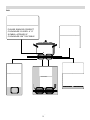
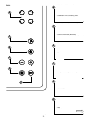
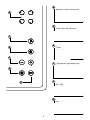
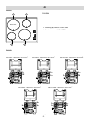
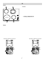
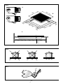
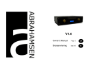
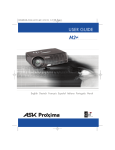
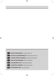
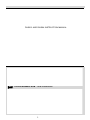
DIHS62 AND DIHS64 INSTRUCTION MANUAL
I
PIANO VETROCERAMICA - Istruzioni per l'uso
D
ELEKTRO-GLASKERAMIKMULDE - Gebrauchsanweisung
E
PLANO DE VIDRO DE CERAMICA - Manual de utilización
F
TABLE VETROCERAMIQUE- Notice d'utilisation
GB
VITROCERAMIC HOB - User instructions
NL
GLASCERAMIEL PLAAT - Gebruiksaanwijzing
P
PLANOVITRO-CERÂMICO - Manual do usuário
DK
GLASKERAMISK KOGEPLADE – Brugervejledning
FIN
LASI-KERAAMINEN KEITTOTASO – Käyttöohje
N
KERAMISK TOPP – Bruksanvisning
S
KERAMISK GLASHÄLL – Bruksanvisning
1.
FIG.1
- Pentola con fondo in materiale ferro-magnetico
- Kochtopf mit Eisen-Magnetboden
- Olla con fondo en material de hierro magnético
- Casserole à fond magnétique
- Pan with ferromagnetic base
- Pan met bodem van ijzer-magnetisch materiaal
- Piano in vetroceramica
PLEASE ENSURE CORRECT
- Gryde med jern-magnetisk bund
COOKWARE IS USED. A "U"
- Magnetoituva keittoastia
APPEARS
IF
-SYMBOL
Kjele med jern-magnetisk
bunn
COOKWARE
ISN'T
SUITABLE
- Kastrull med magnetisk botten
- Glaskeramikkochfeld
- Panela com fundo em material ferromagnético
- Encimera en vidrio cerámica
- Plaque en vitro-céramique
- Glass-ceramic cooker top
- Plaat van glaskeramiek
- Placa em vidro cerâmica
- Glaskeramisk plade
- Keraaminen liesi
- Glasskeramisk topp
- Glaskeramikhäll
- Bobina a spirale di Archimede
- Campo magnetico
- Magnetfeld
- Campo magnético
- Champ magnétique
- Magnetic field
- Magnetisch veld
- Campo magnético
- Magnetisk omrĺde
- Magneettikenttä
- Magnetisk område
- Elektromagnetiskt fält
- Archimedesspiralenspule
-
Generatore
Wärmeerzeuger
Generador
Générateur
Generator
Generator
Generator
-
Gerador
Generaattori
Generator
Generator
2.- 3 -
- Bobina a espiral de Arquímedes
- Bobine à spirale d’Archimède
- Archimedean spiral coil
- Spiraalspoel van Archimedes
- Bobina em espiral de Arquimedes
- Spole i form af Arkimedesspiral
- Archimede -induktiospiraali
- Archimedes spiralspole
- Archimedes spiralspole
FIG.2
B
- Selezione della zona di cottura
- Wahl des Kochbereiches
- Selección de la zona de cocción
B
- Sélection de la zone de cuisson
- Selection of the cooking area
- Selectie van de kookzone
- Selecção da zona de cozedura
F
- Intensificatore di postenza (Booster)
- Leistungssteigerer (Booster)
- Intensificador de potencia (Booster)
- intensificateur de puissance (Booster)
- Power intensifier (Booster)
F
- Versterker van het vermogen (Booster)
- Intensificador de potência (Booster)
E
E
- Timer
- Timer
- Timer
- Timer
- Timer
- Timer
C
- Timer
C
- Tasti di regolazione temperatura
- Temperaturreguliertasten
- Teclas de regulación de la temperatura
A
- Touches de réglages de la températures
- Temperature adjustment keys
- Toetsen voor temperatuurregeling
- Teclas para regular a temperatura
A
D
- ON / OFF
- ON / OFF
- ON / OFF
- ON / OFF
- ON / OFF
- ON / OFF
- ON / OFF
D
- Tasto chiave
- Schlüsseltaste
- Tecla llave
- Touche clé
- Key
- Sleuteltoets
- Tecla chave
-43.
B
- Selection of the cooking area
B
- Valg af kogezone
- Keittoalueiden valinta
- Valg av kokesone
- Val av kokzon
F
- Power intensifier (Booster)
- Kraftforstærker (Booster)
- Booster -toiminto
- Effektforsterker (Booster)
- Snabbökning av temperaturen (Booster)
F
E
E
- Timer
- Signalur/Timer
- Ajastin
- Timer
- Signalur/Timer
C
C
A
-Temperature adjustment keys
-Taster til regulering af temperaturen
-Lämmönsäätelynäppäimet
-Tast for regulering av styrke
-Temperaturregler ingsknappar/
touchkontroller
A
D
- ON / OFF
- ON / OFF
- ON / OFF
- PÅ / AV
- ON / OFF
D
- Key
- Børnelås
- Virtakytkin
- Barnesikring
- Nyckelsymbolen
-54.
4i
FIG.3A
1
1. Zone cottura ad INDUZIONE
DIHS64
1
1. INDUKTIONSkochbereiche
1. Encimera a INDUCCIÓN
1. Zones de cuisson à INDUCTION
BOOSTER
1. Cooking by INDUCTION area
1. Kookzones met INDUCTIE
1. Zonas de cozedura por INDUÇÃO
1. Kogezoner med induktion
1. INDUKTIO -keittoalueet
1
1
1. Soner for koking ved INDUKSJON
1. Induktions kokzon
FIG.3B
220-240V~ H05V2V2-F 3G 2.5mm2
2
220-240V2~ H05V2V2-F 3G 2.5mm
L
N
L1
L2
220-240V3~ H05V2V2-F 3G 2.5mm
L1
2
2
380-415V2N~ H05V2V2-F 3G 2.5mm
L2
N
L1
380-415V3N~ H05V2V2-F 3G 2.5mm
L2
L3
L2
L1
-65.
L3
N
2
2i
FIG.4A
1. Zone cottura ad INDUZIONE
2
2. Zone cottura RADIANTE
DIHS62
2
1. INDUKTIONSkochbereiche
2. STRAHLUNGSkochbereiche
1. Encimera a INDUCCIÓN
2. Encimera RADIANTE
1. Zones de cuisson à INDUCTION
2. Zones de cuisson RADIANTE
1. Cooking by INDUCTION area
2. Cooking by RADIATION area
BOOSTER
1. Kookzones met INDUCTIE
2. Kookzones met STRALING
1
1
1. Zonas de cozedura por INDUÇÃO
2. Zonas de cozedura RADIANTE
1. Kogezoner med induktion
2. Kogezoner med varmefordeling
FIG.4B
1. INDUKTIO -keittoalueet
2. KERAAMISET -keittoalueet
1. Soner for koking ved INDUKSJON
2. Soner for koking ved VANLIGE ELEMENTER
1. Induktions kokzon
2. High Light-element
220-240V~ H05V2V2-F 3G 2.5mm 2
220-240V2~ H05V2V2-F 3G 2.5mm
L
N
L1
L2
-76.
2
FIG.5
A
30 mm
58
0
0-
51
77
B
0
40 mm
5
Mi 0
n
56
0-
0
75
0
49
5
Mi 0
n
25
min.
C
FIG.6
FIG.7
-8-
7.
.5
53 in
M
FIG.8 A
FIG.8 B
50 mm
4 mm
25mm
80 mm
500 x 10
FIG.9 A
FIG.9 B
50 mm
4 mm
40mm
500 x 50
8.
-9-
500 x 10
ENGLISH
GENERAL
Carefully read the contents of this leaflet since it provides important instructions regarding safety of installation, use and maintenance.
Keep the leaflet for possible future consultation. All the
operations relating to installation (electrical connections)
must be carried out by specialised personnel in conformity with the regulations in force.
1.1 THE PRINCIPLE OF INDUCTION
The system of cooking by induction is based on the
physical phenomenon of magnetic induction.
The fundamental feature of this system is direct transfer
of heat energy from the generator to the pan without
intermediate means (different from traditional cooker tops
see fig.1).
GB
- avoid liquid spilling, therefore to boil or heat liquids
reduce the heat supply.
- do not leave the heating elements switched on with
empty vessels or without vessels.
- when you have finished cooking, switch off the relative
resistance using the control indicated below.
- never use aluminium foil for cooking, or never place
products wrapped in aluminium foil onto the cooking
surface. The aluminium would melt and damage your
apparatus irreversibly.
- Never heat a tin or can of food without opening it – it
could explode! This warning applies to hobs of all types.
ATTENTION: Steam cleaners must not be used.
ATTENTION: If the surface is cracked, switch the apparatus off to prevent electric shocks
INSTALLATION INSTRUCTIONS
1.2 ADVANTAGES
If you compare your electric cooker tops, with the
induction cooker top, the result will be:
- Safer: low temperature on the glass surface
- Quicker: brief heating times.
- More precise: the top reacts immediately to your
commands
- More efficient: 90% of the energy absorbed is transformed into heat.
1.3 COOKING VESSELS fig.6
Cooking by induction uses magnetism to generate heat.
The vessels must therefore contain iron.
Check if the vessel material is magnetic using a magnet.
Important:
To prevent permanent damage to the cooker surface, do
not use:
- pans with bases that are not perfectly flat.
- metal pans with enamelled bases.
- Do not use pans with rough bases as they may scratch
the hob’s surface
For best results use pans of the same diameter as the
induction plate, so that they can be recognised by the
magnetic sensor.
SAFETY WARNINGS
This apparatus is not suitable for use by children or
persons who need supervision.
Do not allow children to play with the apparatus.
Before using the induction cooker top it is important to
check that the apparatus is compatible with anyone who
has a pacemaker and active surgical implants.
IMPORTANT
- metal objects such as knives, forks, spoons or lids
must not be placed on the cooker surface as they can
get hot.
- after use, switch the cooker off using the control device
and do not rely on the pan detector.
These instructions address specialised installers and
serve as a guide for installation, adjustment and maintenance in conformity with the laws and regulations in
force.
POSITIONING (fig.5)
The appliance is made for fixing into a worktop, as shown
in the relevant figure. Apply the supplied sealant to the
entire perimeter of the hob and insert it into the fitment
hole (for sizing see fig. 5B).
Fix the appliance into the worktop with the 4 stays, rotating them according to the top’s depth (fig. 5A).
If the underside of the appliance will be accessible after
installation, a separator panel G (fig. 8A) will need to be
mounted maintaining the distances shown (fig. 8B).
If the appliance is installed over an oven the panel is not
necessary (fig. 9A - 9B).
IMPORTANT: if there is an oven under the induction hob
it is advisable for it to have a cooling fan.
Do not use the induction hob while PYROLITIC cleaning is
in process.
WARNING: to allow the circulation of as much fresh air as
necessary, there must be at least 40 mm between the
induction hob module and any appliance installed under
it (fig. 9B).
In any event, adequate aeration must be provided.
To allow fresh air circulation there must be openings in the
kitchen furniture (fig. 8A-9A) of the sizes indicated in fig.
8B-9B.
ELECTRICAL CONNECTIONS (Fig.3B - Fig.4B)
Before making the electrical connections, check that:
- the ground cable is 2 cm longer than the other cables;
- the system ratings meet the ratings indicated on the
identification plate fixed on the lower part of the worktop;
- the system is fitted with efficient earthing compliant
to the laws and regulations in force.
Earthing is obligatory by law.
- 18 9.
If the domestic appliance is not fitted with a cable and/
or relevant plug, use material suited to the absorption
value indicated on the identification plate and the operating temperature. At no point must the cable reach a
temperature 50°C higher than room temperature.
If wishing to make a direct connection to the mains, an
omnipolar switch must be interposed with a minimum
opening of 3 mm between the contacts and suited to the
load indicated on the plate and conform to the regulations in force (the yellow/green ground conductor must
not be interrupted by the switch). When the appliance
has been installed, the omnipolar switch must be easily
reachable.
USE AND MAINTENANCE
USE (Fig.2)
Press key A to switch the cooker top on.
Press one of the keys in section B corresponding to the
cooking area you intend to use.
Select cooking power using the + / - keys in section C
(number 9 on the display corresponds to the maximum
temperature and 1 to the minimum).
You can disconnect the cooking area by pressing the
symbols + and - at the same time.
To prevent use or cleaning of the cooker surface by
children, it is possible to block all functions by pressing
the D key.
If the small hotplate is equipped with an extended hotplate ring then the second zone will activate when the
corresponding knob P is touched and held for 3 seconds (fig. 2 F).
At this point the hotplate will be ignited and the temperature may be regulated using the - or + knobs.
before using it again.
MAINTENANCE
Remove any residues of food and drops of grease from
the cooking surface using the special scraper supplied
on request (Fig.7)
Clean the heated area as thoroughly as possible using
SIDOL, STAHLFIX or similar products and a cloth/paper,
then rinse with water and dry with a clean cloth.
Using the special scraper (optional) immediately remove
any fragments of aluminium and plastic material that
have unintentionally melted on the heated cooking area
or residues of sugar or food with a high sugar content
(Fig.7). In this way, any damage to the cooktop surface
is prevented.
Under no circumstances use abrasive sponges or irritating chemical detergents such as oven sprays or stain
removers.
THE MANUFACTURER DECLINES ALL RESPONSIBILITY FOR EVENTUAL DAMAGES CAUSED BY BREACHING THE ABOVE WARNINGS.
PLEASE NOTE: IF COOKWARE IS
UNSUITABLE OR NO COOKWARE IS
PRESENT A "U" SYMBOL WILL APPEAR
BOOSTER:
The appliance is supplied with a Booster (only in the
cooking area indicated in fig.3A – 4A), on the basis of
the model you own.
To activate the Booster, switch the interested cooking
area on at any power level and press key P (fig. 2F). This
allows to reach higher temperatures in a short time disbursing the maximum power possible. Once the function
is activated a red LED and a P will appear on the display
for ten minutes. After this time the cooking area will
automatically return to power level 9.
If the Booster is activated at the same time in other
parts of the cooking area, the power will be slightly
lessened until the end of functioning.
Timer:
The timer can be used for any selected area.
Select the area where you want to use the timer and
then, by pressing the E key, activate the timer and using
+ and - choose the cooking time.
Once cooking time is over, the timer switches off the
area and deactivates the selection.
An acoustic signal can be heard for 30 seconds indicating
the end of timer activation.
IMPORTANT: To avoid damage to the electronic circuitry,
the hob is equipped with a safety device to prevent
overheating.
Should this cut in, wait until the hob has cooled down
- 19 10.
11.
- 32 -
12.
- 33 -
- 34 13.
-14.
35 -
15.
3LIP0050