1
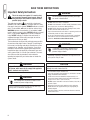
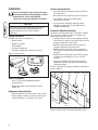
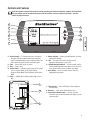
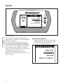
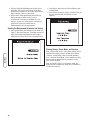
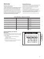
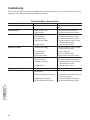
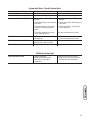
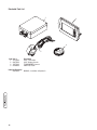
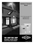
Thank you for your purchase of this Rheem/Ruud
. This product is intended for use with Rheem and Ruud
Home Standby Generator sets ONLY. This is an optional home standby system which provides an alternate source of electric
power and to serve loads such as a gas furnace, refrigeration and communication systems that, when stopped during any
power outage, could cause discomfort, or the like.
This manual contains safety information to make you aware of any hazards and risks associated with StatStation and how to
avoid them. Rheem has made every effort to provide for a safe, streamlined and cost-effective installation. Each installation is
unique, it is impossible to know of and advise of all conceivable procedures and methods by which installation might be
achieved. We do not know all possible hazards and/or the results of each method or procedure. Save these instructions for
future reference.
This StatStation requires installation before use. Refer to the Installation section of this manual for instructions on
installation procedures. Only licensed electrical contractors should install transfer switches. Installations must strictly
comply with all applicable federal, state and local codes, standards and regulations.
Where to Find Us
You never have to look far to find support and service for your StatStation. Consult your Yellow Pages. There are many
Rheem and Ruud authorized service dealers who provide quality service. You can also contact Rheem/Ruud Customer Service
by phone at (877) 369-9400.
StatStation
Model Number
Revision
Serial Number
Date Purchased
Rheem Sales Company
Randleman, NC 27317
(877) 369-9400
Copyright © 2007 Rheem Sales Company. All rights
reserved. No part of this material may be reproduced or
transmitted in any form by any means without the express
written permission of Rheem Sales Company.
Table of Contents
Important Safety Instructions . . . . . . . . . . . . . . . . . . . . . . . . . . . . . . . . . 2
Equipment Description. . . . . . . . . . . . . . . . . . . . . . . . . . . . . . . . . . . . . . . . . 3
Installation . . . . . . . . . . . . . . . . . . . . . . . . . . . . . . . . . . . . . . . . . . . . . 4
Unpack StatStation . . . . . . . . . . . . . . . . . . . . . . . . . . . . . . . . . . . . . . . . . . . 4
Transmitter Mounting Guidelines. . . . . . . . . . . . . . . . . . . . . . . . . . . . . . . . . 4
Sensing Wire Interconnections . . . . . . . . . . . . . . . . . . . . . . . . . . . . . . . . . . 5
Display Console Installation. . . . . . . . . . . . . . . . . . . . . . . . . . . . . . . . . . . . . 6
Controls and Features . . . . . . . . . . . . . . . . . . . . . . . . . . . . . . . . . . . . . . 7
Operation . . . . . . . . . . . . . . . . . . . . . . . . . . . . . . . . . . . . . . . . . . . . . . 8
Setting Up Your StatStation. . . . . . . . . . . . . . . . . . . . . . . . . . . . . . . . . . . . . 8
Viewing the Maintenance Schedules and History . . . . . . . . . . . . . . . . . . . 10
Viewing Outage, Power Mode, and Exercise . . . . . . . . . . . . . . . . . . . . . . . 10
Maintenance . . . . . . . . . . . . . . . . . . . . . . . . . . . . . . . . . . . . . . . . . . . 11
StatStation Maintenance . . . . . . . . . . . . . . . . . . . . . . . . . . . . . . . . . . . . . . 11
Generator Maintenance . . . . . . . . . . . . . . . . . . . . . . . . . . . . . . . . . . . . . . . 11
Resetting StatStation after Generator Maintenance . . . . . . . . . . . . . . . . . . 11
Troubleshooting . . . . . . . . . . . . . . . . . . . . . . . . . . . . . . . . . . . . . . . . . 12
Illustrated Parts List. . . . . . . . . . . . . . . . . . . . . . . . . . . . . . . . . . . . . . . . . . 14
Warranty . . . . . . . . . . . . . . . . . . . . . . . . . . . . . . . . . . . . . . . . . . . . . . 15
Español
Français
1
SAVE THESE INSTRUCTIONS
Important Safety Instructions
This is the safety alert symbol. It is used to alert
you to potential personal injury hazards. Obey all
safety messages that follow this symbol to avoid
possible injury or death.
The safety alert symbol ( ) is used with a signal word
(DANGER, CAUTION, WARNING), a pictorial and/or a safety
message to alert you to hazards. DANGER indicates a hazard
which, if not avoided, will result in death or serious injury.
WARNING indicates a hazard which, if not avoided, could
result in death or serious injury. CAUTION indicates a hazard
which, if not avoided, might result in minor or moderate
injury. NOTICE indicates a situation that could result in
equipment damage. Follow safety messages to avoid or
reduce the risk of injury or death.
The manufacturer cannot possibly anticipate every possible
circumstance that might involve a hazard. The warnings in
this manual, and the tags and decals affixed to the system
components are, therefore, not all-inclusive. If you use a
procedure, work method or operating technique that the
manufacturer does not specifically recommend, you must
satisfy yourself that it is safe for you and others. You must
also make sure that the procedure, work method or
operating technique that you choose does not render the
system unsafe.
WARNING
Only qualified electricians should attempt installation of
this system, which must strictly comply with applicable
codes, standards and regulations.
WARNING
Low voltage wire cannot be installed in same
conduit as power voltage wiring.
• Failure to follow above warning could cause personal injury,
damage and / or malfunction of equipment.
2
WARNING
Failure to observe proper grounding techniques
can result in electrocution.
• DO NOT touch bare wires or receptacles.
• DO NOT install transmitter in home standby installations having
worn, frayed, bare, or otherwise damaged wiring.
• DO NOT handle electrical cords while standing in water, while
barefoot, or while hands or feet are wet.
• If you must work around a unit while it is operating, stand on an
insulated dry surface to reduce shock hazard.
• In case of an accident caused by electrical shock, immediately
shut down the source of electrical power and contact local
authorities. Avoid direct contact with the victim.
WARNING
Transmitter is connected to equipment that
contains hazardous voltage that can cause
personal injury or death.
• Despite the safe design of the system, operating this equipment
imprudently, neglecting its maintenance or being careless can
cause possible injury or death.
CAUTION
Improper treatment of wireless StatStation components can
damage them and shorten their life.
• Use transmitter only for intended uses.
• If you have questions about intended use, ask dealer or contact
Briggs and Stratton Power Products.
• Install and use wireless StatStation components only in a
sheltered or indoors location having an ambient temperature
range of -4 °F to 158 °F (-20 °C to 70 °C).
• DO NOT expose transmitter to excessive moisture, dust, dirt, or
corrosive vapors.
• Remain alert at all times while working on this equipment.
NEVER work on the equipment when you are physically or
mentally fatigued.
• If connected devices overheat, turn them off and turn off their
circuit breaker / fuse.
INTRODUCTION
NOTICE
These devices comply with Part 15 of the FCC Rules.
Operation of the devices is subject to the following:
(A) The devices may not cause harmful interference, and
(B) The devices must accept any interference that may
cause undesired operation.
This equipment has been tested and found to comply with
the limits for a Class B digital device, pursuant to Part 15
of the FCC Rules. These limits are designed to provide
reasonable protection against harmful interference in a
residential installation. This equipment generates, uses, and
can radiate radio frequency energy. If the equipment is not
installed and used in accordance with the instructions, the
equipment may cause harmful interference to radio
communications. There is no guarantee, however, that
such interference will not occur in a particular installation.
Interference to radio or television reception can be
determined by turning the equipment off and on.
Your Rheem / Ruud StatStation is supplied with this
combined “Installation and Operator’s Manual”. This is an
important document and should be retained by the owner
after the installation has been completed.
Every effort has been expended to make sure that the
information in this manual is both accurate and current.
However, the manufacturer reserves the right to change,
alter or otherwise improve the system at any time without
prior notice.
Equipment Description
This wireless StatStation is designed to report on the status
of your home standby system and requires:
• Rheem / Ruud Home Standby Generator with Intelligen
package
• Rheem / Ruud Transfer Switch.
Your home standby system provides an alternate source of
electric power to serve loads such as a gas furnace, a
refrigerator, or a communications system that, when
stopped during any power outage, could cause discomfort or
damage. This wireless StatStation includes a transmitter
which sends the status of your system, including
maintenance requirements and alarms, to a convenient
display console inside your home.
Every effort has been made to provide for a safe, streamlined
and cost-effective installation. Each installation is unique,
and it is impossible to know of and advise of all conceivable
procedures and methods by which installation might be
achieved. We do not know all possible hazards or the results
of each method or procedure.
For these reasons,
Only licensed electrical contractors should install the
transmitter component of your StatStation. Installations
must strictly comply with all applicable federal, state, and
local codes, standards, and regulations.
For the Home Owner
To help you make informed choices and communicate
effectively with your installation contractor(s),
Read and understand the Owner Orientation Section
of this manual BEFORE contracting or starting your
Wireless StatStation transmitter installation.
To arrange for proper installation, contact the store at which
you purchased your Rheem / Ruud StatStation, your dealer,
or your utility power provider.
The StatStation System Warranty is VOID
unless the system is installed by a
licensed electrical professional.
The illustrations depict typical circumstances and are meant
to familiarize you with the installation options available with
your wireless StatStation.
Local codes, appearance, and distances are the factors that
must be considered when negotiating with an installation
professional. As the distance from the existing electrical
service increases, compensation in wiring materials must be
allowed for. This is necessary to comply with local codes
and overcome electrical voltage drops.
The factors mentioned above will have a direct effect on the
overall price of your wireless StatStation installation.
NOTE: Your installer must check local codes AND obtain
permits before installing the system.
NOTICE
Power must be disconnected from display console and
transmitter during the entire installation process or
component failure will occur. Follow installation
instructions!
3
Installation
Installer Responsibilities
Read this Installation section carefully and become
familiar with Homeowner Responsibilities, Installer
Responsibilities, and the figures BEFORE
contracting or starting your StatStation installation.
NOTICE
Power must be disconnected from display console and
transmitter during the entire installation process or
component failure will occur. Follow installation
instructions!
Unpack StatStation
Included in the carton is (See Figure 1):
• Display Console
• Wireless Transmitter
• AC/DC Adapter
• (2) Current transformers
• Installation and Operator’s Manual (not shown)
Figure 1: Carton contents
• Read and observe the Important Safety Instructions in
the Safety section.
• Read and follow the instructions given in this manual.
• Check federal, state, and local codes before
commencing installation.
• If you need more information about the wireless
StatStation system, call (877) 364-9400, between
8:00 AM and 5:00 PM CT.
Transmitter Mounting Guidelines
The wireless StatStation transmitter is enclosed in a NEMA
Type 4 enclosure suitable for indoor use. Guidelines for
mounting the transmitter include:
• Install the switch on a firm, sturdy supporting structure
within 50 feet (15 meters) of the transfer switch and with
the serial number decal clearly visible.
• NEVER install the transmitter where any corrosive
substance might drip onto the enclosure.
• NEVER install the transmitter inside any grounded
metal cabinet or enclosure such as the transfer switch
enclosure.
• NEVER install the transmitter within 10 feet (3 meters)
of another transmitting device, such as a wireless
telephone.
• Protect the transmitter at all times against excessive
temperature, moisture, dust, dirt, lint, construction grit
and corrosive vapors.
A typical installation of the wireless StatStation transmitter is
shown in Figure 2.
Main
Breaker
Panel
Automatic
Transfer
Switch
Wireless
Transmitter
Power
Management
Panel
Items Not Supplied:
• Seven (7) ‘AA’ alkaline (2200mAH) batteries
• Connecting wires
• Mounting hardware and miscellaneous fasteners,
conduit, etc.
Homeowner Responsibilities
• Read and follow the instructions given in this manual.
• Follow a regular schedule in caring for and using your
wireless StatStation, as specified in this manual.
Convenience
Outlet
Figure 2: Typical wireless Transmitter Mounting Location
4
Sensing Wire Interconnections
WARNING
CAUTION
Improper installation can cause damage to the circuit
boards and shorten their life. Installing circuit boards in live
circuits will damage the board is not a warranty condition.
ALWAYS disconnect ALL sources of power prior to
installation.
• Remove all power prior to installing this wireless StatStation
equipment. Failure to do so could cause internal damage to the
components when making electrical connections.
• Turn generator to OFF position.
• Turn off utility power to the home standby generator and
transfer switch.
All wiring must be the proper size, properly supported and
protected by conduit, per code.
Complete the following connections between the wireless
StatStation components, the transfer switch, and the
generator, as shown in Figure 3.
Low voltage wire cannot be installed in same
conduit as power voltage wiring.
• Failure to follow above warning could cause personal injury,
damage and / or malfunction of equipment.
IMPORTANT: Observe the maximum signal wire distance
limitation (50 feet or 15 meters) on wire runs described in
steps 1 to 6 below.
1. Using installer supplied 18AWG stranded wire, connect
transmitter’s ground terminal (J4, 7th terminal from
left), to ‘GND’ terminal on transfer switch control board
(J7, leftmost terminal). See Figure 3.
2. Using installer supplied 18AWG stranded wire, connect
transmitter 8th terminal from left on J4 to ‘T’ terminal
on transfer switch control board (J7, 2nd terminal from
left).
J7
Automatic
Transfer
Switch
Wireless
Transmitter
J8
J4
Main
Circuit
Breaker
Panel
Neutral Bus
Generator
Enclosure
Generator
Control
Panel
TxRx terminals
Ground Bus
Figure 3: Transmitter Wiring Diagram
5
3. Using installer supplied 18AWG stranded wire, connect
transmitter’s 9th terminal from left on J4 to ‘R’ terminal
on transfer switch control board (J7, 3rd terminal from
left).
4. Using installer supplied 18AWG stranded wire, connect
transmitter’s rightmost J4 terminal to ‘+V’ terminal on
transfer switch control board (J7, rightmost terminal).
5. Using installer supplied 18AWG stranded wire, run
sufficient length of a pair of wires through conduit from
transfer switch to generator. Connect ‘GND’ terminal on
transfer switch control board (J8, left terminal) to wire
harness attached to generator control panel at
‘TxRxGND’ position (5th terminal down from top)
6. Using second wire run in 5. above, connect ‘T/S’
terminal on transfer switch control board (J8, right
terminal) to wire harness attached to generator control
panel at ‘TxRx’ position (4th terminal down from top)
7. Install three (3) AA batteries in transmitter. Observe
battery polarity.
This completes the StatStation transmitter installation.
6
Extra Current Transformers were supplied in the event the
home standby system has a Power Management System
already installed. Review the Power Management System
installation instructions to ensure all connections associated
with that system have not been disturbed.
Display Console Installation
1. Find an indoor location for the display console that is
convenient for both viewing status reports and
receiving audible alarms. The location must be within
200 ft (61 m) of the transmitter and have a nearby
electrical receptacle.
2. Insert four (4) AA batteries into the back of the display
console.
3. Attach the AC/DC adapter to the display console and
plug it into the electrical receptacle.
4. Follow the instructions given under Setting Up Your
StatStation in the Operation section.
Controls and Features
Read this operator’s manual and safety rules before operating your wireless StatStation. Compare the illustrations
with your display console to familiarize yourself with the locations of various controls and features. Save this
manual for future reference.
A
B
G
C
H
D
I
E
H
F
A - Signal Strength — The number of bars to the right of
the signal strength symbol indicate how strong the
signal is between display console and transmitter. Zero
bars indicate no signal, five bars maximum signal.
B - Time — Current time of day is shown.
C - Date — Today’s date.
D - System Status — Indicates current status of the system,
such as: System Ready, Utility Power Outage,
Generator Power Mode, Exercise Mode, System Alert
Mode.
E - Alarm — Audible Alarm setting symbol (High, Low, or
Off).
F - Battery Indicator — Battery strength indicator. Five bars
indicate full strength.
G - LED — Two color LED. Green indicates normal
operation. Red indicates system alert.
H - Up/Down Navigation Button — A touch control used to
scroll through displayed menu options. Each touch will
move the on-screen cursor one place up or down.
I - Select Button — A touch control used to select the
highlighted menu option.
J
K
J - TxRx Indicator — Green LED flashes when sending or
receiving data.
K - Batteries — Install three (3) AA batteries here.
L - System Serial Number plate — Use this nine digit
number to synchronize transmitter and display console
communication.
L
7
Operation
Figure 4: Main Menu
Touch any button to activate the StatStation’s display
console when it is in Idle Mode Touch again to display the
Main Menu (see Figure 4).
Pressing one of the two Navigation buttons directs the
cursor up or down so the next option will be highlighted.
When the desired option is highlighted, touch the Select
button. In some screens, the Navigation and Select buttons
help you execute on-screen instructions. If the display
console is left inactive for one minute, it will return to Idle
Mode and the screen backlight will turn off.
The Main Menu will display five options: History,
Maintenance Schedule, System Settings, System Sync, and
Return to Idle Screen.
Setting Up Your StatStation
1. From the Main Menu, scroll until System Settings is
highlighted and press the Select button. The System
Settings menu is displayed (see Figure 5).
Figure 5: System Settings Menu
8
2. Select Date & Time. Follow on-screen commands
within Date Adjust to set the date and do the same in
Time Adjust to set the time. Note that Navigation
buttons are used to set correct numbers and the Select
button will move cursor from one position to the next.
When all positions on the screen are set, select Finish.
The correct time and date will now be displayed on the
left side of the display (see Figure 4). Selecting Return
to Previous Menu will again display the System
Settings menu.
3. Select Audible Alarm. Choose from High, Low, or Off.
The chosen setting is demonstrated and the display
returns to the Audible Alarm Menu. The chosen alarm
will now be displayed on the left side of the display (see
Figure 4). This Alarm will sound when there are certain
System Alerts. Selecting Return to Previous Menu will
again display the Systems Setting Menu.
4. Select Display Screen. From there, select Backlight
Adjust and set to High, Low, or Off. The chosen setting
is demonstrated and the display returns to the Backlight
Adjust Menu. Selecting Return to Previous Menu will
again show the Display Screen menu.
5. Select Contrast Adjust. Navigate to Higher or Lower.
While Higher or Lower is highlighted, each press of the
Select button will move the indicator one increment
right or left. Navigate to Select to select the current
setting.
6. Keep selecting Return to Previous Menu until the Main
Menu appears.
7. Select System Sync and the System Sync Mode will
display (see Figure 6).
Figure 6: System Sync Mode
9
8. Enter the 9-digit Serial Number from the label on the
transmitter (see Controls and Features for location),
following the instructions on the screen. When the last
digit is selected, choose to Synchronize.
9. Select Confirm. After approximately 20 seconds, the
display console will report that the system is
“Synchronized” and return to Idle Mode. Or it may
display a “System Sync Unsuccessful” message and
return to the System Sync Mode. Refer to
Troubleshooting if this message appears.
2. Select Return, then Return to Previous Menu to reach
the Main Menu.
3. Select History to view the system’s Total Run Time and
the time remaining until the Next Exercise (see
Figure 8).
Viewing the Maintenance Schedules and History
1. From the Main Menu select Maintenance Schedule (see
Figure 7), then select Overview. The display console will
report the time remaining before the next change is
required for Air Cleaner, Oil & Filter, and Spark Plug(s).
Figure 8: History Screen
Viewing Outage, Power Mode, and Exercise
Figure 7: Maintenance Menu
10
When a utility outage occurs, “Utility Power Outage” will be
reported on the display console’s system status readout
instead of “System Ready”. After the standby generator
starts, “Generator Power Mode” will be reported until utility
power is again recognized and the generator first cools
down, then shuts down.
When the standby system is in the exercise mode, the
display console will report that, along with a countdown in
minutes of the exercise.
Maintenance
Generator Maintenance
StatStation Maintenance
If alkaline (2200mAH) batteries are used, display console will
operate for up to 40 hours, if the AC/DC Converter is not
used. The transmitter will operate for up to 60 hours after
utility and generator power is lost. A System Alert will be
reported if the transmitter’s batteries are low. The left side of
the display will indicate if the display console’s batteries are
low. Be sure to keep fresh batteries in the components so
your StatStation will be ready for the next outage.
Your StatStation will report the time remaining before certain
maintenance tasks must be performed on your standby
generator. See Viewing the Maintenance Schedules and
History in the Operation section.
If the time interval for scheduled maintenance has passed,
the StatStation will report System Alerts for scheduled
maintenance and the LED will flash red. An audible alarm will
not accompany Maintenance Schedule System Alerts.
The following table lists the events tracked by the system.
System Alert Mode – Maintenance Schedule
System Alert Display
Check Air Cleaner.
Fault Cause
Scheduled maintenance check
Fault Remedy
Check/Replace air cleaner and reset
StatStation.
Replace air cleaner and reset
StatStation.
Replace Air Cleaner.
Total running hours reached
Check Engine Oil Fill Level.
Scheduled maintenance check
Check engine oil fill level and reset
StatStation.
Change Oil & Filter.
Total running hours reached
Check Spark Plugs.
Scheduled maintenance check
Replace oil and filter and reset
StatStation.
Check spark plugs and reset StatStation.
Change Spark Plugs.
Total running hours reached
Replace spark plugs and reset
StatStation.
Resetting StatStation after Generator
Maintenance
Follow the maintenance instructions in the operator’s manual
for your standby generator carefully. Then reset the intervals
on your StatStation.
1. From the Main Menu, navigate to Maintenance
Schedule and select.
2. Navigate to Service Reset and select.
3. Choose which service(s) you would like to put back to
full interval (see Figure 9) and select.
Figure 9: Service Reset
11
Troubleshooting
The StatStation will report System Alerts for problems with your generator and standby system and the LED will flash red. An
audible alarm will accompany Generator and Standby System Alerts.
System Alert Mode – Generator Faults
System Alert Display
Low Battery Voltage
Fault Cause
1. Generator battery is low.
Fault Remedy
1. Recharge or replace generator
battery.
Low Oil Pressure
1. Engine oil level is low.
2. Engine oil leaks.
1. Generator circuit breaker open.
2. Fault in generator.
3. Fault in connection.
4. Insufficient fuel supply.
1. Add oil to full mark on dipstick.
2. Contact authorized service center.
1. Close generator circuit breaker.
2. Contact authorized service center.
3. Contact authorized service center.
4. Check fuel delivery system. Contact
authorized service center.
5. Clogged air filter.
1. Insufficient fuel supply.
5. Clean or replace air filter.
1. Check fuel delivery system. Contact
authorized service center.
2. Faulty spark plugs.
3. Clogged air filter.
4. Faulty engine ignition.
1. Fault in generator.
2. Fault in connection.
3. Insufficient fuel supply.
2. Check spark plug.
3. Clean or replace air filter.
4. Contact authorized service center.
1. Contact authorized service center.
2. Contact authorized service center.
3. Check fuel delivery system. Contact
authorized service center.
4. Clogged air filter.
1. Failed engine governor.
1. Generator access doors removed
while running.
4. Clean or replace air filter.
1. Contact authorized service center.
1. Install generator access doors.
2. Obstructed cooling air inlet screens.
2. Check and clean generator cooling air
inlet or exhaust port.
3. Clogged engine cooling fins.
4. Faulty temperature switch/wiring.
3. Contact authorized service center.
4. Contact authorized service center.
Low Voltage
Engine Fails to Start
Low Frequency
Engine Overspeed
High Oil Temperature
12
System Alert Mode – Standby System Faults
System Alert Display
Switch G Coil Fail
Switch U Coil Fail
Generator Start Switch in OFF Position
Fuse Fail
One Wire Communication Fail
Transmitter Battery Low
Fault Cause
1. Transfer switch generator coil failure.
1. Transfer switch utility coil failure.
1. Generator start switch in OFF
position.
Fault Remedy
1. Contact authorized service center.
1. Contact authorized service center.
1. Set generator switch to AUTO
position.
2. StatStation display too far away from
transmitter.
2. Locate display within 200 ft (60 m) of
transmitter.
3. Transmitter located in an area that
interferes with the transmitter RF
signal.
3. Locate transmitter in a location free
of RF interference.
4. Transmitter, generator, or transfer
switch signal wiring fault.
4. Contact authorized service center.
1. 2 Amp fuse in transfer switch failed. 1. Check/replace fuse.
2. Wiring failure.
2. Contact authorized service center.
1. Signal wire failure between generator, 1. Contact authorized service center.
transfer switch, and transmitter.
1. Transmitter batteries low.
1. Replace transmitter batteries.
StatStation System Fault
System Sync Unsuccessful
1. Batteries exhausted.
2. Display console too far from
transmitter or other signal
interference.
1. Replace with fresh AA batteries.
2. Move console closer to transmitter.
Replace transmitter AA batteries.
13
Illustrated Parts List
1
2
3
4
Item
1
2
3
4
Part #
197138GS
202756GS
195728GS
201092GS
Items Not Illustrated
202766GS
14
Description
ASSY, Transmitter
ASSY, Display Console
TRANSFORMER, Current
ADAPTER, AC/DC
MANUAL, Installation & Operator’s
Warranty
BRIGGS & STRATTON POWER PRODUCTS GROUP, LLC ACCESSORY WARRANTY POLICY
Effective July 1, 2006 replaces all undated Warranties and all Warranties dated before July 1, 2006
LIMITED WARRANTY
Briggs & Stratton Power Products Group, LLC will repair or replace, free of charge, any part(s) of the accessory that is defective in material or
workmanship or both. Transportation charges on product submitted for repair or replacement under this warranty must be borne by purchaser. This
warranty is effective for the time periods and subject to the conditions stated below. For warranty service, find the nearest Authorized Service Dealer in
our dealer locator map at BRIGGSandSTRATTON.com.
THERE IS NO OTHER EXPRESS WARRANTY. IMPLIED WARRANTIES, INCLUDING THOSE OF MERCHANTABILITY AND FITNESS FOR A PARTICULAR
PURPOSE, ARE LIMITED TO NINETY DAYS FROM PURCHASE, OR TO THE EXTENT PERMITTED BY LAW. ANY IMPLIED WARRANTIES ARE
EXCLUDED. LIABILITY FOR INCIDENTAL OR CONSEQUENTIAL DAMAGES ARE EXCLUDED TO THE EXTENT EXCLUSION IS PERMITTED BY LAW.
Some states or countries do not allow limitations on how long an implied warranty lasts, and some states or countries do not allow the exclusion or
limitation of incidental or consequential damages, so the above limitation and exclusion may not apply to you. This warranty gives you specific legal
rights and you may also have other rights which vary from state to state or country to country.
WARRANTY PERIOD
Consumer Use
90 days
Commercial Use
90 days
The warranty period begins on the date of purchase by the first retail consumer or commercial end user, and continues for the period of time stated above.
“Consumer use" means personal residential household use by a retail consumer. “Commercial use" means all other uses, including use for commercial,
income producing or rental purposes. Once the product has experienced commercial use, it shall thereafter be considered as commercial use for purposes of
this warranty.
NO WARRANTY REGISTRATION IS NECESSARY TO OBTAIN WARRANTY ON BRIGGS & STRATTON PRODUCTS. SAVE YOUR PROOF OF PURCHASE
RECEIPT. IF YOU DO NOT PROVIDE PROOF OF THE INITIAL PURCHASE DATE AT THE TIME WARRANTY SERVICE IS REQUESTED, THE MANUFACTURING
DATE OF THE PRODUCT WILL BE USED TO DETERMINE THE WARRANTY PERIOD.
ABOUT YOUR WARRANTY
We welcome warranty repair and apologize to you for being inconvenienced. Any Authorized Service Dealer may perform warranty repairs. Most warranty
repairs are handled routinely, but sometimes requests for warranty service may not be appropriate. For example, warranty service would not apply if
equipment damage occurred because of misuse, lack of routine maintenance, shipping, handling, warehousing or improper installation. Similarly, the
warranty is void if the manufacturing date or the serial number on the accessory has been removed or the equipment has been altered or modified. During the
warranty period, the Authorized Service Dealer, at its option, will repair or replace any part that, upon examination, is found to be defective under normal use
and service. This warranty will not cover the following repairs and equipment:
•
Normal Wear: Outdoor Power Equipment, like all mechanical devices, needs periodic parts and service to perform well. This warranty does not cover
normal maintenance such as adjustments and cleaning.
•
Installation and Maintenance: This warranty does not apply to equipment or parts that have been subjected to improper or unauthorized installation or
alteration and modification, misuse, negligence, accident, overloading, improper maintenance, repair or storage so as, in our judgment, to adversely
affect its performance and reliability.
•
Other Exclusions: This warranty excludes wear items such as connectors, seals, batteries, or damage or malfunctions resulting from accidents, abuse,
modifications, alterations, or improper servicing or freezing or chemical deterioration. This warranty excludes used, reconditioned, and demonstration
equipment and failures due to acts of God and other force majeure events beyond the manufacturers control. 198208E, Rev A, 12/14/2006
BRIGGS & STRATTON POWER PRODUCTS GROUP, LLC
JEFFERSON, WI, USA
15
Reserved