1
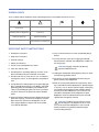
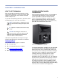
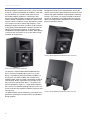
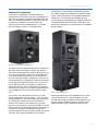
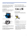
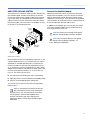
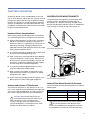
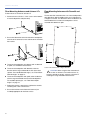
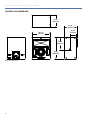
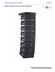
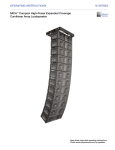
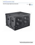
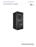
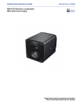
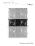
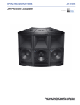
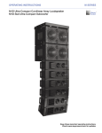
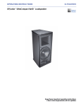
OPERATING INSTRUCTIONS Acheron® Screen Channel Loudspeakers Acheron 100, Acheron 80, and Acheron LF Keep these important operating instructions. Check www.meyersound.com for updates. DECLARATION OF CONFORMITY ACCORDING TO ISO/IEC GUIDE 22 AND EN 45014 Manufacturer’s Name: Meyer Sound Laboratories Inc. Manufacturer’s Address: 2832 San Pablo Avenue Berkeley, CA 94702-2204, USA Declares that the product: Product Names: Acheron 80 Screen Channel Loudspeaker System Acheron 100 Screen Channel Loudspeaker System Acheron LF Screen Channel Loudspeaker System Product Options: All Conforms to the following Product Specifications: Safety: EN 60065:2002 EMC: EN55103-1: 1997 emission1 EN55103-2: 1997 immunity2 This device also complies with EN 55103-1 & -2. Operation is subject to the following two conditions: (1) this device may not cause harmful interference, and (2) this device must accept any interference received, including interference that may cause undesired operation. Supplementary Information: The product herewith complies with the requirements of the Low Voltage Directive (LVD) 2006/95/EC and the EMC Directive 2004/108/EC. Signature: Ms. Margie Garza Director of Quality Meyer Sound Laboratories Inc. Berkeley, California 94702 USA Issued October 27, 2008 European Contact: Your local Meyer Sound dealer or Meyer Sound Germany, GmbH. © 2009, 2010 Meyer Sound. All rights reserved. Acheron Operating Instructions, PN 05.188.005.01 B The contents of this manual are furnished for informational purposes only, are subject to change without notice, and should not be construed as a commitment by Meyer Sound Laboratories Inc. Meyer Sound assumes no responsibility or liability for any errors or inaccuracies that may appear in this manual. Except as permitted by applicable copyright law, no part of this publication may be reproduced, stored in a retrieval system, or transmitted, in any form or by any means, electronic, mechanical, recording or otherwise, without prior written permission from Meyer Sound. EXP, Intelligent AC, MAPP Online Pro, RMS, QuietCool, and all alpha-numeric designations for Meyer Sound products and accessories are trademarks of Meyer Sound. Acheron, Compass, Galileo, Meyer Sound, the Meyer Sound wave logo, and SIM are registered trademarks of Meyer Sound Laboratories Inc. (Reg. U.S. Pat. & Tm. Off.). All third-party trademarks mentioned herein are the property of their respective trademark holders. ii SYMBOLS USED These symbols indicate important safety or operating features in this booklet and on the chassis: ! Dangerous voltages: risk of electric shock Important operating instructions Frame or chassis Protective earth ground Pour indiquer les risques résultant de tensions dangereuses Pour indequer important instructions Masse, châssis Terre de protection Warnung vor gefährlicher elektrischer Spannung Wichtige Betriebsanweisung oder Gebrauchsanleitung Rahmen oder Gehäuse Masse Schutzleiter Para indicar voltajes peligrosos Instrucciones importantes de funcionamiento y/o manteniento Armadura o chassis Tierra proteccionista IMPORTANT SAFETY INSTRUCTIONS 1. Read these instructions. 2. Keep these instructions. 3. Heed all warnings. 4. Follow all instructions. 11. Only use attachments/accessories specified by Meyer Sound. 12. Use only with the caster rails or rigging specified by Meyer Sound, or sold with the loudspeaker. Handles are for carrying only. 5. Do not use this loudspeaker near water. 6. Clean only with dry cloth. 7. Do not block any ventilation openings. Install in accordance with Meyer Sound’s installation instructions. 8. Do not install near any heat sources such as radiators, heat registers, stoves, or other apparatus that produce heat. 9. Do not defeat the safety purpose of the grounding-type plug. A grounding type plug has two blades and a third grounding prong. The third prong is provided for your safety. If the provided plug does not fit into your outlet, consult an electrician for replacement of the obsolete outlet. 10. Protect the power cord from being walked on or pinched, particularly at plugs, convenience receptacles, and the point where they exit from the loudspeaker. The AC mains plug or appliance coupler shall remain readily accessible for operation. ! CAUTION: Rigging should only be done by experienced professionals. 13. Unplug this loudspeaker during lightning storms or when unused for long periods of time. 14. Disconnect the mains plug before disconnecting the power cord from the loudspeaker. 15. Refer all servicing to qualified service personnel. Servicing is required when the loudspeaker has been damaged in any way, such as when the power-supply cord or plug has been damaged; liquid has been spilled or objects have fallen into the loudspeaker; rain or moisture has entered the loudspeaker; the loudspeaker has been dropped; or when for undetermined reasons the loudspeaker does not operate normally. CAUTION: To reduce the risk of electric shock, do not expose this loudspeaker to rain or moisture. Do not install the loudspeaker in wet or humid locations without using weather protection equipment from Meyer Sound. ! iii SAFETY SUMMARY English To reduce the risk of electric shock, disconnect the loudspeaker from the AC mains before installing audio cable. Reconnect the power cord only after making all signal connections. Connect the loudspeaker to a two-pole, three-wire grounding mains receptacle. The receptacle must be connected to a fuse or circuit breaker. Connection to any other type of receptacle poses a shock hazard and may violate local electrical codes. Do not install the loudspeaker in wet or humid locations without using weather protection equipment from Meyer Sound. Do not allow water or any foreign object to get inside the loudspeaker. Do not put objects containing liquid on or near the unit. To reduce the risk of overheating the loudspeaker, avoid exposing it to direct sunlight. Do not install the unit near heat-emitting appliances, such as a room heater or stove. Ne pas installer l’haut-parleur dans un endroit où il y a de l’eau ou une humidité excessive. Ne pas laisser de l’eau ou tout objet pénétrer dans l’haut-parleur. Ne pas placer de r´cipients contenant un liquide sur cet appareil, ni à proximité de celuici. Pour éviter une surchauffe de l’hautparleur, conserver-la à l’abri du soleil. Ne pas installer à proximité d’appareils dégageant de la chaleur tels que radiateurs ou appareils de chauffage. Ce haut-parleur contient des circuits haute tension présentant un danger. Ne jamais essayer de le démonter. Il n’y a aucun composant qui puisse être réparé par l’utilisateur. Toutes les réparations doivent être effectuées par du personnel qualifié et agréé par le constructeur. Um die Gefahr eines elektrischen Schlages auf ein Minimum zu reduzieren, den Lautsprecher vom Stromnetz trennen, bevor ggf. ein Audio-Schnittstellensignalkabel angeschlossen wird. Das Netzkabel erst nach Herstellung aller Signalverbindungen wieder einstecken. Der Lautsprecher an eine geerdete zweipolige Dreiphasen-Netzsteckdose anschließen. Die Steckdose muß mit einem geeigneten Abzweigschutz (Sicherung oder Leistungsschalter) verbunden sein. Der Anschluß der unterbrechungsfreien Stromversorgung an einen anderen Steckdosentyp kann zu Stromschlägen führen und gegen die örtlichen Vorschriften verstoßen. This loudspeaker contains potentially hazardous voltages. Do not attempt to disassemble the unit. The unit contains no user-serviceable parts. Repairs should be performed only by factorytrained service personnel. iv Pour réduire le risque d’électrocution, débrancher la prise principale de l’hautparleur, avant d’installer le câble d’interface allant à l’audio. Ne rebrancher le bloc d’alimentation qu’après avoir effectué toutes les connections. Branchez l’haut-parleur dans une prise de courant à 3 dérivations (deux pôles et la terre). Cette prise doit être munie d’une protection adéquate (fusible ou coupe-circuit). Le branchement dans tout autre genre de prise pourrait entraîner un risque d’électrocution et peut constituer une infraction à la réglementation locale concernant les installations électriques. Um ein Überhitzen dem Lautsprecher zu verhindern, das Gerät vor direkter Sonneneinstrahlung fernhalten und nicht in der Nähe von wärmeabstrahlenden Haushaltsgeräten (z.B. Heizgerät oder Herd) aufstellen. Im Inneren diesem Lautsprecher herrschen potentiell gefährliche Spannungen. Nicht versuchen, das Gerät zu öffnen. Es enthält keine vom Benutzer reparierbaren Teile. Reparaturen dürfen nur von ausgebildetem Kundenienstpersonal durchgeführt werden. Español Para reducir el riesgo de descarga eléctrica, desconecte de la red de voltaje el altoparlante antes de instalar el cable de señal de audio. Vuelva a conectar la alimentacion de voltaje una vez efectuadas todas las interconexiones de señalizacion de audio. Conecte el altoparlante a un tomacorriente bipolar y trifilar con neutro de puesta a tierra. El tomacorriente debe estar conectado a la protección de derivación apropiada (ya sea un fusible o un disyuntor). La conexión a cualquier otro tipo de tomacorriente puede constituir peligro de descarga eléctrica y violar los códigos eléctricos locales. No instale el altoparlante en lugares donde haya agua o humedad excesiva. No deje que en el altoparlante entre agua ni ningún objeto extraño. No ponga objetos con líquidos encima de la unidad ni cerca de ella. Para reducir el riesgo de sobrecalentamiento, no exponga la unidad a los rayos directos del sol ni la instale cerca de artefactos que emiten calor, como estufas o cocinas. Este altoparlante contiene niveles de voltaje peligrosos en potencia. No intente desarmar la unidad, pues no contiene piezas que puedan ser repardas por el usuario. Las reparaciones deben efectuarse únicamente por parte del personal de mantenimiento capacitado en la fábrica. Deutsch Français Der Lautsprecher nicht an einem Ort aufstellen, an dem sie mit Wasser oder übermäßig hoher Luftfeuchtigkeit in Berührung kommen könnte. Darauf achten, daß weder Wasser noch Fremdkörper in das Innere den Lautsprecher eindringen. Keine Objekte, die Flüssigkeit enthalten, auf oder neben die unterbrechungsfreie Stromversorgung stellen. CONTENTS Chapter 1: Introduction How to Use This Manual Acheron Screen Channel Loudspeaker Chapter 2: Power Requirements AC Connector AC Power Distribution Acheron Voltage Requirements Acheron Current Requirements Powering Up the Acheron Electrical Safety Guidelines Chapter 3: Amplification and Audio Audio Connectors Limiting Amplifier Cooling System Chapter 4: Integrating Acheron LF Loudspeakers Integrating Acheron LF Loudspeakers Galileo Loudspeaker Management System Using Digital Signal Processors and Crossovers with Acheron Systems Chapter 5: Mounting Acheron Floor Mount Brackets Acheron Stacking Bracket Chapter 6: The RMS Remote Monitoring System RMS Software RMS Module Resetting the RMS Module Chapter 7: System Design and Integration Tools MAPP Online Cinema SIM 3 Measurement System 7 7 7 11 11 12 12 12 13 13 15 15 16 17 19 19 20 20 21 21 24 29 29 30 31 33 33 34 Appendix A: Acheron 80 and Acheron 100 Specifications 35 Appendix B: Acheron LF Specifications 39 v CONTENTS vi CHAPTER 1: INTRODUCTION HOW TO USE THIS MANUAL Make sure to read these operating instructions in their entirety before configuring a system with Acheron® loudspeakers. In particular, pay close attention to material related to safety issues. As you read these operating instructions, you will encounter the following icons for notes, tips, and cautions: NOTE: A note identifies an important or useful piece of information relating to the topic under discussion. ACHERON SCREEN CHANNEL LOUDSPEAKER At the heart of Meyer Sound's EXP line of cinema products is the Acheron high-performance screen channel loudspeaker. Optimized for installation behind perforated screens, the two-way loudspeaker combines the advantages of self-powered technology and innovative horn design to deliver exceptional, precise coverage for the left, right, and center sound channels for cinema. TIP: A tip offers a helpful tip relevant to the topic at hand. CAUTION: A caution gives notice that an action may have serious consequences and could cause harm to equipment or personnel, or could cause delays or other problems. ! Information and specifications are subject to change. Updates and supplementary information are available at www.meyersound.com. Meyer Sound Technical Support is available at: ■ Tel: +1 510 486.1166 ■ Tel: +1 510 486.0657 (after hours support) ■ Web: www.meyersound.com/support ■ Email: [email protected] Acheron 100 Screen Channel Loudspeaker The Acheron loudspeaker is available in two full-range models: the Acheron 100, with a 100-degree horizontal by 50degree vertical horn, which is ideal for wide theatres; and the Acheron 80, with an 80-degree horizontal by 50-degree vertical horn, which is suitable for narrow theatres and rerecording, production, and post-production facilities. The Acheron horn (patent pending) was specifically designed for cinema use and features a very soft roll-off outside the extremely well behaved coverage angle. The horn is fixed within the enclosure to ensure an accurate acoustic crossover, phase response, and an incredibly consistent vertical pattern between the low and high frequencies. The Acheron’s 580 Hz crossover point places most of the dialog in the horn, which is ideal for cinema applications. 7 CHAPTER 1: INTRODUCTION Boasting a frequency response of 38 Hz to 17 kHz at ±4 dB, as well as a generous peak output of 139 dB at 1 meter with very low distortion, the Acheron stands up to the most demanding of digital soundtracks, maintaining a wide dynamic range and full fidelity. Designed and manufactured at Meyer Sound's headquarters in Berkeley, California, the Acheron's drivers include one 15-inch low-frequency neodymium magnet cone driver and one high-frequency 4-inch diaphragm compression driver. The drivers yield uncompromising quality and full bandwidth, making the Acheron suitable for small and medium theatres, re-recording stages, and production and post-production facilities. When pairing an Acheron with an Acheron LF, the system offers enough headroom for large theatres. Strategically placed 3/8-inch threaded points on the side corners of the Acheron cabinet allow the unit to be secured to floors with uptilt or downtilt using the optional mounting brackets. The Acheron can also be mounted on top of the Acheron LF loudspeaker, with uptilt or downtilt, using the optional stacking brackets. Both brackets are available for purchase from Meyer Sound. Acheron 100 with Optional Floor Mount Brackets, Front View Acheron 80 Screen Channel Loudspeaker The Acheron's sophisticated onboard amplification produces consistent and predictable results in any system design. The proprietary Meyer Sound power amplifier is a two-channel, class AB/H amplifier with complementary MOSFET output stages that yields a total output of 1685 W (3370 W peak). Built-in signal processing includes an electronic crossover and correction filters — to achieve a flat phase and frequency response — along with driver protection circuitry. The self-powered design not only ensures consistent results but also simplifies installation in both new and existing rooms. The optional RMS™ remote monitoring system allows comprehensive monitoring of system parameters on a Windows®based computer. 8 Acheron 100 with Optional Floor Mount Brackets, Rear View ACHERON OPERATING INSTRUCTIONS Acheron LF Loudspeaker The Acheron LF loudspeaker can be paired with the Acheron 80 or Acheron 100 screen channel loudspeaker to deliver the low-frequency headroom required by larger theatres. The self-powered Acheron LF with dual 15-inch drivers boosts the headroom on the LCR channels by converting each Acheron loudspeaker to a system with three low-frequency drivers in an aligned column. The Acheron LF is powered by an onboard two-channel class AB/H amplifier with complementary MOSFET output stages. Total output power is 2250 W (4500 W peak) and provides the system with enough headroom to easily accommodate the extreme demands of digital soundtracks. The optional RMS remote monitoring system allows comprehensive monitoring of system parameters on a Windowsbased computer. Acheron LF Screen Channel Loudspeaker The unique multi-way, gradated design offers smooth coverage and maximum low-frequency impact with all drivers active at the lowest frequencies and each rolling off, one at a time, via the integral active crossover. This technique eliminates interference between drivers that would otherwise occur at shorter wavelengths, enabling the system to maintain ideal polar, phase, and frequency responses throughout the low and low-mid operating ranges. As a result, the system can deliver the necessary power to completely fill a large theatre with rich, clean sound, thereby ensuring that the full intensity and nuance so carefully crafted into today’s movie soundtracks reach every listener without compromise. The Acheron LF was designed exclusively for use with Acheron loudspeakers. The Acheron LF's 37 Hz to 370 Hz operating frequency range and 136 dB maximum peak SPL (at 1 meter) were carefully chosen to compliment the Acheron. The Acheron LF also features the same highpower 15-inch cone driver used in the low frequency section of the Acheron. Engineered to deliver optimum performance, the high-excursion, back-vented drivers include 4-inch voice coils and are housed in a tuned, vented enclosure that shares the same rectangular footprint as the Acheron. Acheron LF with Acheron 80 Strategically placed 3/8-inch threaded points on the side corners of the Acheron LF cabinet allow the unit to be secured to floors with the optional mounting brackets. An Acheron can be mounted on top of the Acheron LF with uptilt or downtilt using the optional stacking brackets. 9 CHAPTER 1: INTRODUCTION 10 CHAPTER 2: POWER REQUIREMENTS The Acheron loudspeaker combines advanced loudspeaker technology with equally advanced power capabilities. Understanding power distribution, voltage and current requirements, and electrical safety guidelines is critical to the safe operation of the Acheron. AC Power Cable with Edison Adapter The Acheron can be powered from a standard three-prong Edison outlet with an L6-20 to Edison adapter (available for purchase from Meyer Sound; PN 27.033.024.03). AC CONNECTOR The Acheron AC connector supplies AC power to the unit and is located on its rear user panel. The Acheron can be equipped with one of the following AC connectors: ■ L6-20 to Edison AC Power Cable Adapter AC Connector Wiring IEC 309 male inlet connector. When wiring international or special-purpose AC power cables and connectors, use the following wiring scheme: Blue = neutral Brown = hot Neutral (blue) Line (brown) Ground (green/yellow) ■ Yellow/green = earth ground (chassis NEMA L6-20 (twistlock) male inlet AC Cable Wiring Scheme Ground (green/yellow) X-neutral (blue) ■ Connect the blue wire to the black terminal, or the terminal marked with an N. ■ Connect the brown wire to the red terminal, or the terminal marked with an L. ■ Connect the yellow and green wire to the green (or green and yellow) terminal, or the terminal marked with an E. Y-line (brown) The Acheron requires a grounded outlet. To operate safely and effectively, it is extremely important that the entire system be properly grounded. If you replace the included AC power cable, make sure to use a cable that is wired correctly and equipped with the with the appropriate power plug (on the other end) for the area in which you will operate the unit. CAUTION: When creating AC power cables and distribution systems, it is important to preserve AC line polarity and connect the earth ground on both ends of the cable. The Acheron requires a grounded connection. Always use a grounded outlet and plug. It is extremely important that the system be properly grounded to operate safely and properly. Do not ground-lift the AC cable. ! 11 CHAPTER 2: POWER REQUIREMENTS AC POWER DISTRIBUTION ACHERON VOLTAGE REQUIREMENTS All components in an audio system (self-powered loudspeakers, processors, etc.) must be properly connected to an AC power distribution system, to ensure that AC line polarity is preserved and that all grounding points are connected to a single node or common point using the same cable gauge as the neutral and line cables. The Acheron operates safely and continuously when the AC voltage stays within 85–134 V AC and 165–264 V AC at 50 or 60 Hz. The loudspeaker allows any combination of voltage to GND (neutral-line-ground or line-line-ground). NOTE: Improper grounding of connections between loudspeakers and the rest of the audio system may produce noise or hum, or cause serious damage to the input and output stages of the system’s electronic components. If the voltage drops below 85 V (brownout), the Acheron uses stored power to continue operating temporarily; the loudspeaker will shut down if the voltage does not rise above the low boundary before the stored power is used. If the voltage rises above 275 V, the power supply could become damaged. CAUTION: The power source for the Acheron should always operate within the required voltage range, at least a few volts from the upper and lower ranges. This ensures that AC voltage variations from the service entry — or peak voltage drops due to cable runs — will not cause the loudspeaker’s amplifier to cycle on and off or cause damage to the power supply. ! CAUTION: Before applying AC power to any Meyer Sound self-powered loudspeaker, make sure that the voltage potential difference between the neutral and earth-ground lines is less than 5 V AC. ! Figure 1 illustrates a basic three-phase AC distribution system with the loudspeaker load distributed across the three phases. All loudspeakers are connected to common neutral and earth-ground lines. TIP: Since the Acheron does not require a dedicated neutral line, and it can tolerate elevated voltages from the ground line, it can be connected to line-line terminals in 120 V, 3-phase Wye systems. This results in 208 V AC between lines (nominal) and therefore draws less current than when using 120 V AC (line-neutral). Make sure that the voltage remains within the Acheron’s recommended operating windows (85–134 V AC and 165–264 V AC). The ground line must always be used for safety reasons and the line-to-ground voltage should never exceed 250 V AC (typically 120 V AC from line-to-ground). ACHERON CURRENT REQUIREMENTS Line 1 Line 2 Line 3 Neutral Earth Ground Figure 1: AC Power Distribution System 12 The current draw for the Acheron is dynamic and fluctuates as operating levels change. Since different cables and circuit breakers heat up at varying rates, it is important to understand the following types of current ratings and how they affect circuit breaker and cable specifications. ■ Idle Current — The maximum rms current during idle periods. ■ Maximum Long-Term Continuous Current — The maximum rms current during a period of at least 10 seconds. The Maximum Long-Term Continuous Current is used to calculate temperature increases for cables, to ensure that cable sizes and gauges conform to electrical code standards. The current rating is also used as a rating for slow-reacting thermal breakers. ACHERON OPERATING INSTRUCTIONS ■ Burst Current — The maximum rms current during a period of around one second. The Burst Current is used as a rating for magnetic breakers. It is also used for calculating the peak voltage drop in long AC cable runs according to the following formula: V pk (drop) = I pk x R (cable total) ■ Ultimate Short-Term Peak Current — A rating for fastreacting magnetic breakers. ■ Inrush Current — The spike of initial current encountered when powering on. You can use Table 1 and Table 2 as guidelines for selecting cable gauges and circuit breaker ratings for the system’s operating voltage. Table 1: Acheron 100 and Acheron 80 Current Draw POWERING UP THE ACHERON When AC power is applied to the Acheron its Intelligent AC™ power supply automatically selects the correct operating voltage, allowing it to be used internationally without manually setting voltage switches. In addition, Intelligent AC suppresses high-voltage transients up to several kilovolts, filters common mode and differential mode radio frequencies (EMI), and sustains operation temporarily during low-voltage periods. When powering up the Acheron, the following startup events take place over several seconds. 1. Audio output is muted. 2. Voltage is detected and the power supply mode is automatically adjusted as necessary. Current Draw 115 V AC 230 V AC 100 V AC 3. The primary ultra low-noise fan turns on. Idle Current 0.71 A rms 0.38 A rms 0.79 A rms 4. The power supply ramps up. Maximum Long-Term Continuous Current 5.8 A rms 2.8 A rms 6.3 A rms 5. The green Active LED on the user panel lights up, indicating the loudspeaker is ready to output audio. Burst Current 6.4 A rms 3.2 A rms 7.2 A rms Ultimate Short-Term Peak Current 26 A peak 14 A peak 28 A peak Inrush Current 7 A peak 7 A peak 10 A peak CAUTION: If the Active LED does not light up, or the Acheron does not output audio after ten seconds, remove AC power immediately and verify that the voltage is within the required range. If the problem persists, contact Meyer Sound Technical Support. ! Table 2: Acheron LF Current Draw Current Draw 115 V AC 230 V AC 100 V AC Idle Current 0.64 A rms 0.32 A rms 0.85 A rms Maximum Long-Term Continuous Current 8.8 A rms 4.4 A rms 10.0 A rms Burst Current 19 A rms 9.5 A rms 22 A rms Ultimate Short-Term Peak Current 39 A peak 20 A peak 45 A peak Inrush Current 7 A peak 7 A peak 10 A peak The minimum electrical service amperage required by an Acheron loudspeaker system is the sum of the Maximum Long-Term Continuous Current for each loudspeaker. An additional 30 percent above the minimum amperage is recommended to prevent peak voltage drops at the service entry. CAUTION: If either of the loudspeaker’s circuit breakers trip (the white center buttons disengage), make sure to disconnect the AC power cable and wait one minute, to allow the stored power to dissipate, before resetting the breakers. If necessary, contact Meyer Sound for repair information. ! ELECTRICAL SAFETY GUIDELINES Pay close attention to these important electrical and safety guidelines. ■ The Acheron requires a grounded outlet. Always use a grounded outlet and plug. Earth ground NOTE: For best performance, the AC cable voltage drop should not exceed 10 V, or 10 percent at 115 V and 5 percent at 230 V. Make sure that even with AC voltage drops that the AC voltage always remains within the operating windows. Chassis ground 13 CHAPTER 2: POWER REQUIREMENTS ■ Make sure the AC power cable for the loudspeaker has the appropriate power plug (on the other end) for the area in which you will operate the loudspeaker. ■ Do not operate the unit if the power cable is frayed or broken. ■ Keep all liquids away from the Acheron to avoid hazards from electrical shock. 14 CHAPTER 3: AMPLIFICATION AND AUDIO The Acheron drivers are powered by a two-channel proprietary Meyer Sound amplifier with MOSFET output stages. The audio signal is processed with an electronic crossover, correction filters for phase and frequency response, and driver protection circuitry. Each channel has peak and rms limiters that prevent driver over-excursion and regulate the temperature of the voice coil. The Acheron rear panel has an audio Input and Loop output connector, Limit LEDs, and an optional RMS module for connecting to the RMS remote monitoring system (see Chapter 6, “The RMS Remote Monitoring System”). AUDIO CONNECTORS The Acheron and Acheron LF include female XLR Input and male XLR Loop output connectors. Pins 2 and 3 carry the input as a differential signal. Pin 1 is connected to earth through a 220 kOhm, 1000 pF, 15 V clamped network. This circuitry provides virtual ground lift for audio frequencies while allowing unwanted signals to bleed to ground. Make sure to use standard, balanced XLR audio cables with all three pins connected on both ends. Telescopic grounding is not recommended, and shorting an input connector pin to the case may cause a ground loop, resulting in hum. TIP: If unwanted noise or hiss is produced by the loudspeaker, disconnect its input cable. If the noise stops, there is most likely nothing wrong with the loudspeaker. To locate the source of the noise, check the audio cable, source audio, and AC power. Loop Output Connector The male XLR Loop output connector allows Acheron and Acheron LF loudspeakers to be looped from a single audio source. For applications that require multiple Acherons and Acheron LFs, connect the Loop output of the first unit to the Input of the second, and so forth. Acheron Audio Connectors, Input and Loop Output Input Connector The female XLR Input connector accepts a balanced audio signal with an input impedance of 10 kOhm. The connector uses the following wiring: ■ Pin 1 — 220 kOhm to chassis and earth ground (ESD clamped) ■ Pin 2 — Signal (+) ■ Pin 3 — Signal (–) ■ Case — Earth (AC) ground and chassis NOTE: The order in which loudspeakers are connected when looping audio signals is unimportant. The Loop connector is wired in parallel to the Input connector and transmits the unbuffered source signal even when the Acheron is powered off. To avoid distortion when looping multiple Acherons, make sure the source device can drive the total load impedance of the looped loudspeakers. In addition, the source device must be capable of delivering approximately 20 dBV (10 V rms into 600 ohms) to yield the maximum peak SPL over the entire operating bandwidth of the loudspeakers. Most professional audio equipment can transmit these source levels. To calculate the load impedance for the looped loudspeakers, divide 10 kOhms (the input impedance for a single Acheron) by the number of looped loudspeakers. For example, the load impedance for 10 Acheron loudspeakers is 1000 ohms (10 kOhms / 10). To drive this number of looped loudspeakers, the source device should have an output impedance of 100 ohms or less. This same rule applies when looping Acheron loudspeakers with other self-powered Meyer Sound loudspeakers and subwoofers. 15 CHAPTER 3: AMPLIFICATION AND AUDIO NOTE: Most source devices are capable of driving loads no smaller than 10 times their output impedance. CAUTION: Make sure that all cabling for ! looped loudspeakers is wired correctly (Pin 1 to Pin 1, Pin 2 to Pin 2, and so forth) to prevent the polarity from being reversed. If one or more loudspeakers in a system have reversed polarity, frequency response and coverage will be significantly degraded. Limiting LEDs Behavior for the Acheron Limit LEDs is described below: ■ The low- and high-frequency drivers for the Acheron 80 and Acheron 100 are powered by separate amplifier channels, each with their own limiter. Limiting activity is indicated with a High Limit LED for the high-frequency channel, and a Low Limit LED for the low-frequency channel. ■ The two low-frequency drivers for the Acheron LF are powered by separate amplifier channels that are routed to a single limiter. When a safe power level is exceeded in either channel, limiting is engaged for both channels and the Low Limit LED lights. LIMITING Acheron loudspeakers employ Meyer Sound’s advanced TruPower® limiting. Conventional limiters assume a constant loudspeaker impedance and set the limiting threshold by measuring voltage alone. This method is inaccurate because loudspeaker impedances change as frequency content in the source material changes, and as thermal values for the loudspeaker’s voice coil and magnet vary. Consequently, conventional limiters often begin limiting prematurely, which reduces system headroom and dynamic range. When engaged, the limiters not only protect the drivers but also prevent signal peaks from causing excessive distortion in the amplifier channels, thereby preserving headroom and maintaining smooth frequency responses at high levels. When levels returns to normal, below the limiter thresholds, limiting ceases. The Acheron performs within its acoustical specifications at normal temperatures when the Limit LEDs are unlit, or if the LEDs are lit for two seconds or less and then turn off for at least one second. If the LEDs remain lit for longer than three seconds, the loudspeaker enters hard limiting where: ■ Increases to the input level have no effect. ■ Distortion increases due to clipping and nonlinear driver operation. ■ The drivers are subjected to excessive heat and excursion, which will compromise their life span and may eventually lead to damage over time. CAUTION: The Limit LEDs indicate when a safe, optimum level is exceeded. If the Acheron 80s or Acheron 100s in a system begin to limit before reaching the required SPL, consider adding Acheron LFs to the system (see Chapter 4, “Integrating Acheron LF Loudspeakers”). ! Acheron Limit LEDs In contrast, TruPower limiting anticipates varying loudspeaker impedances by measuring both current and voltage to compute the actual power dissipation in the voice coil. This improves performance, both before and during limiting, by allowing the driver to produce the maximum SPL across its entire frequency range. TruPower limiting also eliminates power compression at high levels over lengthy periods, which helps regulate voice coil temperatures, thereby extending the life of the driver. NOTE: Since TruPower limiting only reduces signal levels to keep voice coil temperatures under a safe margin, signal peaks remain unaffected. 16 NOTE: Acheron loudspeakers use optical limiters that add no noise and have no effect on the signal when the limiters are not engaged and the Limit LEDs are not lit. ACHERON OPERATING INSTRUCTIONS AMPLIFIER COOLING SYSTEM Dust and the Amplifier Module The Acheron uses a forced-air cooling system with two fans (one variable-speed, ultra low-noise primary fan and one reserve fan) to prevent the amplifier module from overheating. The fans draw air in through ducts on the front of the cabinet, over the heat sink, and out the rear of the cabinet. Because dust does not accumulate in the amplifier circuitry, its life span is increased significantly. Operating the Acheron in dusty environments, or for prolonged, intensive periods, may cause dust to accumulate along its airflow path, thereby preventing normal cooling. Under these circumstances, it may be necessary to periodically remove the air intake foam and use compressed to air to clear the dust from the foam and air ducts. Power supply In addition, if the amplifier gets unusually hot, you should remove the amplifier module and use compressed air to clear any dust from its heat sink. ! CAUTION: Make sure to unplug the AC power from the Acheron before cleaning its amplifier. CAUTION: To keep the Acheron from getting too hot, allow for proper ventilation, 3–4 inches, behind the loudspeaker. ! Lownoise fans Heat sink/ amplifier Air intake Air filter Airflow for the Acheron When the Acheron heat sink temperature is below 42° C, the variable-speed primary fan runs continuously at its slowest speed with an inaudible operating noise. The primary fan increases speed when the heat sink temperature reaches 42° C; the primary reaches full speed at 62° C and is barely audible near the cabinet, even without an audio signal. If the the heat sink temperature reaches 74° C, the reserve fan turns on. The reserve fan turns on if: ■ The primary fan has failed (check status immediately) ■ High source levels are encountered for extended periods ■ Dust has accumulated along the cooling path The reserve fan turns off when the heat sink temperature lowers to 68° C. NOTE: In the unlikely event that the reserve fan does not keep the Acheron heat sink temperature below 85° C, the unit automatically shuts down until AC power is removed and reapplied. If the Acheron shuts down again after cooling and reapplying AC power, contact Meyer Sound for repair information. 17 CHAPTER 3: AMPLIFICATION AND AUDIO 18 CHAPTER 4: INTEGRATING ACHERON LF LOUDSPEAKERS INTEGRATING ACHERON LF LOUDSPEAKERS To meet the SPL and low frequency headroom requirements of large rooms, the Acheron 100 or Acheron 80 can be daisy-chained with the Acheron LF loudspeaker, creating a system with three low frequency drivers and one high frequency driver. Adding an Acheron LF yields approximately a 10 dB boost in the low frequency range, depending on loading conditions and room acoustics. The Acheron LF has been carefully designed so its frequency and phase responses compliment the Acheron. The Acheron LF has the same low end frequency response as the Acheron (38 Hz) and rolls off at 320 Hz to avoid any interference in the crossover region of the Acheron. ■ At 38 Hz to 150 Hz, all three low frequency drivers are active. At 150 Hz, the bottom Acheron LF low frequency driver rolls off. ■ At 150 Hz to 300 Hz, two low frequency drivers are active: the top Acheron LF driver and the Acheron low frequency driver. At 300 Hz, the top Acheron LF low frequency driver rolls off. ■ At 300 Hz to 580 Hz, only the Acheron low frequency driver is active, which enables a smooth crossover to the high frequency driver. High frequency Low frequency Acheron 100 Low frequency Low frequency Acheron LF This unique multi-way, gradated design offers smooth coverage and maximum low-frequency impact with all drivers active at the lowest frequencies and each rolling off, one at a time, via the internal active crossover. This technique eliminates interference between drivers that would otherwise occur at shorter wavelengths, enabling the system to maintain ideal polar, phase, and frequency responses throughout the low and low-mid operating ranges. As a result, the system can deliver the necessary power to completely fill a large theatre. Achieving a Flat Frequency Response with an Acheron / Acheron LF Stack Acheron 100 with Acheron LF When the Acheron and Acheron LF are daisy-chained (using the Loop output connector on the user panel) an approximate boost of 10 dB at 110 Hz results, depending on the loading conditions and room acoustics. To achieve a flat frequency response in this configuration, a single parametric filter with the following characteristics can be applied to the signal: Right Center Left Filter type Parametric Frequency 110 Hz Bandwidth 2 (Q = 0.6667) Amplitude –10 dB Screen Acheron LCR System with Acheron LFs CAUTION: When daisy-chaining Acherons and Acheron LFs, make sure the audio cables are wired correctly to avoid polarity reversals. ! 19 CHAPTER 4: INTEGRATING ACHERON LF LOUDSPEAKERS GALILEO LOUDSPEAKER MANAGEMENT SYSTEM The Galileo® loudspeaker management system was designed by Meyer Sound as a comprehensive solution for driving and aligning loudspeakers, especially those comprised of its self-powered loudspeakers. A range of Galileo systems are available, depending on the needs of system, with each including hardware processors with low-latency outputs and processing that includes gain, polarity, delay, low- and high-pass filters, and equalization (parametric and TruShaping). The Galileo processors can be controlled from the extensive Compass™ software running on a Windows or Mac® computer. The Galileo system also interfaces seamlessly with Meyer Sound’s SIM® 3 audio analyzer. USING DIGITAL SIGNAL PROCESSORS AND CROSSOVERS WITH ACHERON SYSTEMS Full-range signals can be connected directly to Meyer Sound self-powered loudspeakers because they have builtin active crossovers. External crossovers and digital signal processors are optional and should be used with caution as they can introduce phase shifts that cause destructive cancellations. If a digital signal processor is used to drive an Acheron LCR system, the Acherons and Acheron LFs should be driven from the same processor to keep their delay times the same. Otherwise a phase shift between the loudspeakers may be encountered. In addition, you should verify the delay time between channels: some digital signal processors may incur channel-to-channel delays when the processor is near maximum throughput, which becomes more likely as the number of filters in use by the processor is increased. In no case should a filter higher than the 2nd order be used on source signals. The additional phase shift introduced by these filters deteriorates the impulse response, and the higher roll-off does not improve crossover interaction. If loudspeakers will be driven directly from a digital signal processor, make sure the signal is sufficient to drive the total load impedance of the connected loudspeakers (see “Loop Output Connector” on page 15). TIP: To address the collective concerns of system design verification, subwoofer integration, digital signal processors, delay systems, and acoustical conditions, a measurement system like Meyer Sound’s SIM 3 is strongly recommended. 20 CHAPTER 5: MOUNTING Strategically placed 3/8-inch threaded points on the side corners of the Acheron cabinet allow the unit to be secured to floors with uptilt or downtilt using the optional mounting brackets. The Acheron can also be mounted on top of the Acheron LF loudspeaker, also with uptilt or downtilt, using the optional stacking brackets. Both brackets are available for purchase from Meyer Sound. ACHERON FLOOR MOUNT BRACKETS The Acheron floor mount brackets secure Acheron loudspeakers to floors with downtilt and uptilt angles of 0–18 degrees (in 3-degree increments). The floor mount brackets should also be used with Acheron LF loudspeakers when stacking an Acheron on top of the Acheron LF. Important Safety Considerations! When installing Meyer Sound loudspeakers and subwoofers, the following precautions should always be observed: ■ All Meyer Sound products must be used in accordance with local, state, federal, and industry regulations. It is the owner’s and user’s responsibility to evaluate the reliability of any mounting and rigging method for their application. Mounting and rigging should only be carried out by experienced professionals. ■ Use mounting and rigging hardware that has been rated to meet or exceed the weight being hung. ■ Make sure to attach mounting hardware to the building's structural components (studs or joists), and not just to the wall surface. Verify that the building's structure and the anchors used for the installation will safely support the total weight of the mounted loudspeakers. ■ Use mounting hardware appropriate for the surface where the loudspeaker will be installed. ■ Make sure bolts and eyebolts are tightened securely. Meyer Sound recommends using Loctite® on eyebolt threads and safety cables. ■ Inspect mounting and rigging hardware regularly. Immediately replace any worn or damaged components. Acheron Floor Mount Brackets Acheron with Floor Mount Brackets Acheron Floor Mount Bracket Kit Contents Acheron and Acheron LF Side Screws The Acheron and Acheron LF ship with four 3/8-16 x 1.5inch screws installed on each loudspeaker side (eight total). These screws and threaded points are used to secure the floor mount and stacking brackets to the loudspeakers. CAUTION: If the Acheron side screws are ! removed to install the brackets, make sure to always reinstall the screws, and tighten them securely. If the side screws are not present when using the loudspeakers, air leakage will result, which will adversely affect frequency response. The Acheron floor mount kit (PN 40.188.026.01) includes the following parts. Part Part number Quantity Acheron floor mount bracket (left) 64.188.042.01 1 Acheron floor mount bracket (right) 64.188.043.01 1 113.509 4 Flat washers NOTE: The 3/8-16 x 1.5-inch screws required for securing the floor mount brackets to the Acheron are shipped with the loudspeaker installed in the two bottom screw holes on each side (four total). 21 CHAPTER 5: MOUNTING Floor Mounting Acherons and Acheron LFs To floor mount an Acheron or Acheron LF: 1. Remove the two 3/8-16 x 1.5-inch screws at the bottom of each loudspeaker side (four total). Floor Mounting Acherons with Downtilt and Uptilt The Acheron floor mount brackets can mount loudspeakers with downtilt or uptilt. Available angles are 3-18 degrees in 3-degree increments. The direction in which the brackets are oriented determines whether the loudspeaker can be mounted with downtilt or uptilt. 2. Secure the left bracket to the left side of the loudspeaker with two of the removed screws and two of the included flat washers. Front –3° ■ To mount the loudspeaker at 0 degrees with no downtilt or uptilt, use the bottom bracket holes. ■ To mount the loudspeaker with downtilt, orient the bracket with the large end toward the rear of the loudspeaker. For available downtilt angles, see “Floor Mount Downtilt Angles” on page 23. ■ To mount the loudspeaker with uptilt, orient the bracket with the large end toward the front of the loudspeaker. For available uptilt angles, see “Floor Mount Uptilt Angles” on page 23. 3. Repeat the previous step with the right bracket and the remaining two screws and washers. 4. Secure the brackets to the floor with fasteners (not included) appropriate for the floor surface. 22 Acheron Floor Mounted with 3-Degree Downtilt CAUTION: When using the floor mount brackets with an Acheron LF that will also have an Acheron stacked on top of it, mount the Acheron LF at 0 degrees using the bottom bracket holes. ! ACHERON OPERATING INSTRUCTIONS Floor Mount Downtilt Angles Floor Mount Uptilt Angles When the floor mount brackets are oriented with the bracket’s large end toward the rear of the loudspeaker, the Acheron can be mounted with downtilt angles of 3-18 degrees in 3-degree increments. When the floor mount brackets are oriented with the bracket’s large end toward the front of the loudspeaker, the Acheron can be mounted with uptilt angles of 3-18 degrees in 3-degree increments. –18° –15° –12° –9° –6° –3° +18° +15° +12° +9° +6° +3° Attach here for uptilt Attach here for downtilt Acheron Floor Mount Bracket Oriented for Downtilt Acheron Floor Mount Bracket Oriented for Uptilt The small end of the bracket attaches to the loudspeaker using the top hole. The large end of the bracket attaches to the loudspeaker with one of the angled holes. The small end of the bracket attaches to the loudspeaker using the top hole. The large end of the bracket attaches to the loudspeaker with one of the angled holes. Front Front –3° –6° +3° +6° –12° –18° +12° –18° Acheron Floor Mount Downtilt Angles Acheron Floor Mount Uptilt Angles 23 CHAPTER 5: MOUNTING ACHERON STACKING BRACKET Acheron Stacking Bracket Kit Contents One Acheron can be stacked on top of the Acheron LF and secured with the Acheron stacking brackets. The stacked Acheron can be mounted with downtilt and uptilt angles of 0–16 degrees. The Acheron stacking bracket kit (PN 40.188.025.01) includes the following parts. NOTE: The orientation of the Acheron to the Acheron LF with the stacking bracket was carefully optimized to minimize any acoustical artifacts between the loudspeakers, as well as between the loudspeakers and baffle walls. Part Part number Quantity Acheron stacking bracket (left) 45.188.043.01 1 Acheron stacking bracket (right) 45.188.044.01 1 3/8-16 x 1.5” shoulder screws 101.507 4 Large 1/2” flat washers 113.531 4 Small Flat washers 113.509 4 NOTE: The 3/8-16 x 1.5-inch screws required for securing the stacking bracket to the Acheron LF are shipped with the Acheron LF installed in the top two screw holes on each side of the unit (four total). Stacking Acherons on Acheron LFs To stack an Acheron on top of an Acheron LF: Acheron Stacking Brackets 1. Secure the Acheron LF to the floor with the floor mount brackets at 0 degrees using the bottom bracket holes. For more information, see “Floor Mounting Acherons and Acheron LFs” on page 22. 2. Stack the Acheron on top of the Acheron LF. TIP: Optionally place two 1 x 2-inch wood pieces (not included) across the top of the Acheron LF, between it and the Acheron. The resulting extra space between the loudspeakers will make it easier to align the Acheron screw holes with the brackets. 1” x 2” wood pieces Acheron and Acheron LF with Stacking Brackets CAUTION: When stacking an Acheron on top of an Acheron LF, the Acheron LF must be secured to the floor with the floor mount brackets. Floor mount the Acheron LF at 0 degrees using the bottom bracket holes. ! 24 ACHERON OPERATING INSTRUCTIONS 3. Remove the two 3/8-16 x 1.5-inch screws at the top of each side of the Acheron LF (four total). These screws will be used to secure the stacking bracket to the Acheron LF. 6. Secure the right bracket to the right side of the Acheron LF with the remaining two screws (previously removed) and the remaining two small flat washers. Install the bracket so its rubber gasket faces the loudspeaker. 7. Secure the stacking brackets to the Acheron with the four 3/8-16 x 1.5-inch shoulder screws and four large 1/2-inch washers (both included with the Acheron stacking bracket kit). Insert the shoulder screws in the bracket’s top slots but don’t yet tighten them completely. 4. Remove the two 3/8-16 x 1.5-inch screws at the bottom of each side of the Acheron (four total). These screws will not be needed for installing the stacking bracket. 5. Secure the left bracket to the left side of the Acheron LF with two of the removed screws and two of the small flat washers (included in the Acheron stacking bracket kit). Use the bracket’s bottom screw holes and install the bracket so its rubber gasket faces the loudspeaker. Shoulder screws and larger washers TIP: If necessary, tip the Acheron slightly to align its screw holes with the bracket holes. Gasket side toward loudspeaker 8. Adjust the angle of the stacked Acheron — anywhere between 0 and 16 degrees — by tilting the unit up or down so the screws slide through bracket slots. 9. Tighten all four shoulder screws to secure the stacking bracket to the Acheron. ■ To mount the Acheron with downtilt, orient the bracket with the large end toward the rear of the loudspeakers. For available downtilt angles, see “Stack Mount Downtilt Angles” on page 26. ■ To mount the Acheron with uptilt, orient the bracket with the large end toward the front of the loudspeakers. For available uptilt angles, see “Stack Mount Uptilt Angles” on page 27. 25 CHAPTER 5: MOUNTING Stacking Acherons with Downtilt and Uptilt Stack Mount Downtilt Angles The Acheron stacking brackets can mount Acherons with either downtilt or uptilt. Available angles are anywhere from 0–16 degrees. The direction in which the brackets are oriented determines whether the loudspeaker can be mounted with downtilt or uptilt. When the stacking brackets are oriented with the bracket’s large end toward the rear of the loudspeakers, the Acheron can be mounted with downtilt angles of up to 16 degrees. –16° –8° 0° Acheron Floor Mount Bracket Oriented for Downtilt Make sure to install the brackets so the rubber gasket faces the loudspeaker. This ensures that the loudspeaker will not get scratched when adjusting the downtilt angle. Front –8° Acheron LF and Stacked Acheron with 16-Degree Downtilt CAUTION: When stacking an Acheron on top of an Acheron LF, the Acheron LF must be secured to the floor with the floor mount brackets. In addition, the Acheron LF should not be mounted with downtilt or uptilt. ! Acheron Floor Mount Downtilt Angles 26 –16° ACHERON OPERATING INSTRUCTIONS Stack Mount Uptilt Angles When the stacking brackets are oriented with the bracket’s large end toward the front of the loudspeakers, the Acheron can be mounted with uptilt angles of up to 16 degrees. +16° +8° 0° Acheron Floor Mount Bracket Oriented for Uptilt Make sure to install the brackets so the rubber gasket faces the loudspeaker. This ensures that the loudspeaker will not get scratched when adjusting the uptilt angle. Front +8° +16° Acheron Floor Mount Uptilt Angles 27 CHAPTER 5: MOUNTING 28 CHAPTER 6: THE RMS REMOTE MONITORING SYSTEM An optional RMS remote monitoring system module can be installed in the Acheron, allowing it to be connected to an RMS network. RMS allows real-time monitoring of multiple Meyer Sound self-powered loudspeakers from a Windowsbased computer. The RMS host computer communicates with Meyer Sound loudspeakers (equipped with RMS modules) via a simple twisted pair network, or an Ethernet network using an FT-10 to Ethernet adapter. NOTE: For the latest RMS system requirements, go to www.meyersound.com. RMS SOFTWARE RMS software provides extensive system status and performance data for each loudspeaker, including amplifier voltage, limiting activity, power output, fan and driver status, as well as mute and solo capability. Loudspeakers are added to the RMS network and assigned a node name during a onetime commissioning procedure where the loudspeaker is identified by either entering its unique Neuron ID, or by pressing its Service button. NOTE: RMS-equipped loudspeakers include a Mute Jumper to enable the loudspeaker’s mute and solo capability. Meyer Sound currently ships RMS-equipped loudspeakers with the Mute Jumper installed. These mute-enabled loudspeakers can be identified by the blue “ME” sticker on the face of the RMS module. Older RMS-equipped loudspeakers can easily be mute-enabled by installing the Mute Jumper. For more information, refer to the RMS User Guide. NOTE: The RMS software allows you to disable Mute and Solo functions to eliminate any possibility of accidentally muting loudspeakers. Mute and solo capability can also be disabled by removing the Mute Jumper from RMS modules. For more information, refer to the RMS User Guide. RMS Add Loudspeaker Dialog Box Once loudspeakers are identified on the RMS network, they appear in the RMS software as icons and views; they are also automatically added to the RMS database on the host computer. NOTE: RMS does not control AC power. Acheron 80 RMS Icons 29 CHAPTER 6: THE RMS REMOTE MONITORING SYSTEM The RMS software displays all loudspeakers on the network in a panel with icons, Meter views, and Text views that can be customized to suit your needs. Loudspeaker data is updated 2–5 times per second. Individual loudspeakers can be physically identified with the Wink option in RMS, which lights the Wink LED on the RMS module for that particular loudspeaker. Conversely, a loudspeaker can be identified in the RMS software by pressing the Service button on the loudspeaker’s RMS module. RMS MODULE The RMS user panel has three LEDs, two buttons, and two Network connectors. RMS Module NOTE: The LEDs and buttons on the RMS user panel are used exclusively by RMS and have no effect on the acoustical or electrical activity of the Acheron. Service LED (Red) The red Service LED provides the following feedback: ■ When unlit, the loudspeaker is successfully connected to the network and commissioned. ■ When blinking once every two seconds, the loudspeaker is connected to the network but not yet commissioned in the RMS software. ■ When lit continuously, the loudspeaker’s RMS hardware has failed and may indicate that the module has been damaged (contact Meyer Sound Technical Support). RMS User Panel Loudspeaker icons and views can be arranged to represent how the loudspeakers have been deployed in the system. Multiple panels can be saved and recalled for specific performances and venues. NOTE: When the Acheron heat sink reaches 85° C (185° F), the On/Temp LED turns red, while its loudspeaker icon in the RMS software turns yellow — indicating the loudspeaker is running hot, but still within safe operating limits. Make sure that the loudspeaker is properly ventilated. Service Button Pressing the Service button identifies the loudspeaker on the RMS network and notifies the RMS software that the loudspeaker is connected. You can simultaneously press the Reset and Service buttons to reset the RMS module and decommission the loudspeaker from the network (see “Resetting the RMS Module” on page 31). Wink LED (Green) The green Wink LED lights when a signal is sent from the RMS software by clicking the Wink button on the loudspeaker’s icon or on its Text view. This is useful for identifying the physical loudspeaker corresponding to a loudspeaker icon in the RMS software. 30 ACHERON OPERATING INSTRUCTIONS Reset Button Pressing the Reset button causes the RMS module’s firmware to reboot; this will not affect whether the loudspeaker is commissioned (which is stored in flash memory). You can simultaneously press the Reset and Service buttons to reset the RMS module and decommission the loudspeaker from the network (see “Resetting the RMS Module” on page 31). Activity LED (Green) The green Activity LED flashes continuously when the loudspeaker has been successfully commissioned. Network Connectors The two Weidmuller connectors transfer data to and from the RMS network. Two connectors are provided to allow for easy connection of multiple (daisy-chained) loudspeakers on the network. Included with each RMS-equipped loudspeaker are RMS cable connectors and mounting blocks for constructing RMS cables. The RMS blocks allow the cables to be securely attached to the RMS module with screws. RESETTING THE RMS MODULE You can use the Reset and Service buttons to reset the RMS module, which will cause the module to be decommissioned from the network. To reset the RMS module: 1. Press and hold the Service button for 10 seconds. 2. While continuing to hold down the Service button, press and hold the Reset button for 5 seconds. 3. After releasing the Reset button, continue holding down the Service button for 5 seconds. The RMS module is reset and the loudspeaker is decommissioned. The RMS module’s red Service LED blinks. 31 CHAPTER 6: THE RMS REMOTE MONITORING SYSTEM 32 CHAPTER 7: SYSTEM DESIGN AND INTEGRATION TOOLS Meyer Sound offers two comprehensive tools to assist with the acoustical and functional requirements of system design and optimization. This chapter introduces MAPP Online Cinema, Meyer Sound’s patented online acoustical prediction tool, and SIM 3, a comprehensive system for measurement and analysis. MAPP ONLINE CINEMA MAPP Online Cinema is a powerful, cross-platform, Javabased application for accurately predicting the coverage pattern, frequency response, impulse response, and maximum SPL output of Meyer Sound cinema loudspeakers. Residing on your local computer, the MAPP Online Cinema client lets you configure Meyer Sound loudspeaker systems and define the environment in which they will operate, including air temperature, pressure, humidity, and even the location and composition of walls. CAD (DXF) files containing detailed venue information can also be imported. The key to the accuracy of MAPP Online Cinema’s predictions is its exhaustive database of Meyer Sound loudspeaker measurements. Performance predictions for each loudspeaker are based on 360 1/48th-octave-band measurements taken with a SIM audio analyzer in the Meyer Sound anechoic chamber. The extraordinary consistency between Meyer Sound loudspeakers guarantees that predictions from MAPP Online Cinema will closely match their actual performance. MAPP Online Cinema predictions are requested by the client software and sent via the Internet to the high-speed Meyer Sound servers where high-resolution (magnitude and phase) polar data is processed with sophisticated acoustical prediction algorithms. The resulting predictions are then returned to and displayed on the local computer running the MAPP Online Cinema client software. TIP: Meyer Sound offers seminars and webinars on using MAPP Online Cinema. For more information, visit www.meyersound.com. MAPP Online Cinema Applications With MAPP Online Cinema, you can: MAPP Online Cinema Sound system designers can use MAPP Online Cinema to accurately predict the appropriate loudspeaker deployment for each job, complete with coverage data, system delay and equalization settings, and detailed design illustrations. MAPP Online Cinema’s accurate, high-resolution predictions ensure that systems will perform as expected, thereby eliminating unexpected coverage problems and minimizing on-site adjustments. ■ Simulate different loudspeaker configurations to refine system design and zero-in on the best coverage for intended audience areas ■ Monitor loudspeaker interactions to locate destructive interferences so that loudspeakers can be re-aimed and repositioned as necessary ■ Place microphones anywhere in the sound field and predict their frequency response, impulse response, and sound pressure ■ Determine delay settings for surround loudspeakers ■ Try out virtual Galileo equalization to determine optimum real-world settings for the best system response ■ Generate and export system images for client presentations 33 CHAPTER 7: SYSTEM DESIGN AND INTEGRATION TOOLS Using MAPP Online Cinema Source Independent Measurement Technique MAPP Online Cinema is compatible with the following operating systems: The SIM 3 audio analyzer implements Meyer Sound’s source independent measurement technique, a dual-channel method that accommodates statistically unpredictable excitation signals. Any excitation signal within a desired frequency range can be used to obtain highly accurate measurements for acoustical or electronic systems. For example, concert halls and loudspeaker systems can be captured during a performance and used as a SIM 3 test signal, so you can: ■ Windows ■ Linux® ■ Unix® ■ Mac OS® 10.4 and later Downloading and Installing MAPP Online Cinema To use MAPP Online Cinema, you can register at the following link: http://meyersound.com/products/mapponline/cinema/ register/ After entering your registration information, an email will be sent to you with your user name, password, and the MAPP Online Cinema download location. On-screen instructions will guide you through the download and installation process. The MAPP Online Cinema client software is regularly upgraded to add support for the latest Meyer Sound loudspeakers, as well as to add feature enhancements. Most upgrades are downloaded automatically when logging on to a MAPP Online Cinema session. The MAPP Online Cinema database includes all Meyer Sound EXP screen channel loudspeakers, surround loudspeakers, subwoofers, and processors. ■ View measurement data as amplitude versus time (impulse response) or amplitude and phase versus frequency (frequency response) ■ Utilize a single-channel spectrum mode ■ View frequency domain data within a logarithmic frequency axis ■ Determine and internally compensate for propagation delays using the SIM 3 Delay Finder SIM 3 Applications The SIM 3’s primary applications are testing and aligning loudspeaker systems, which entails: ■ Measuring propagation delays between subsystems to determine appropriate polarities and delay times ■ Measuring variations in frequency response caused by the acoustical environment and the placement and interaction of loudspeakers to determine corrective equalization SIM 3 MEASUREMENT SYSTEM ■ Optimizing subwoofer integrations The SIM 3 audio analyzer is a high-resolution audio measurement system comprised of software, hardware, microphones, and accessory cables. The SIM 3 is optimized for measuring audio frequencies with resolutions up 1/48th of an octave, allowing you to apply precise corrections to balance system response using frequency and phase domain information. ■ Optimizing loudspeaker arrays 34 The SIM 3 is also versatile and accurate enough for the following applications: ■ Microphone calibration and equalization ■ Transducer evaluation and correction ■ Echo detection and analysis ■ Vibration analysis ■ Architectural acoustics ■ Underwater acoustics APPENDIX A: ACHERON 80 AND ACHERON 100 SPECIFICATIONS Acheron 80 and Acheron 100 Specifications ACOUSTICAL Operating Frequency Range 37 Hz – 18 kHz Note: Recommended maximum operating frequency range. Response depends on loading conditions and room acoustics. Frequency Response 38 Hz – 17 kHz ±4 dB Note: Measured free field with 1/3 octave frequency resolution at 4 meters. Phase Response 700 Hz to 17 kHz ±30° Maximum Peak SPL 139 dB Note: Measured free field with music referred to 1 meter. Dynamic Range >110 dB Coverage Acheron 80: 80° horizontal by 50° vertical Acheron 100: 100° horizontal by 50° vertical Crossover 580 Hz Note: At this frequency, both transducers produce equal sound pressure levels. TRANSDUCERS Low Frequency One high-power 15” cone driver with neodymium magnet Nominal impedance: 4 Ω Voice coil size: 4” Power-handling capability: 1200 W (AES) Note: Power handling measured using AES standards: transducer driven continuously for two hours with a band limited noise signal having a 6 dB peak-average ratio. High Frequency One 4” compression driver Nominal impedance: 8 Ω Voice coil size: 4” Diaphragm size: 4” Exit size: 1.5” Power-handling capability: 250 W (AES) Note: Power handling measured using AES standards: transducer driven continuously for two hours with a band limited noise signal having a 6 dB peak-average ratio. AUDIO INPUT Type Differential, electronically balanced Maximum Common Mode Range ±15 V DC, clamped to earth for voltage transient protection Connectors Female XLR input with male XLR loop output Input Impedance 10 kΩ differential between pins 2 and 3 Wiring Pin 1: Chassis/earth through 220 kΩ, 1000 pF, 15 V clamp network to provide virtual ground lift at audio frequencies Pin 2: Signal + Pin 3: Signal – Case: Earth ground and chassis DC Blocking None on input, DC block through signal processing CMRR >50 dB, typically 80 dB (50 Hz – 500 Hz) RF Filter Common mode: 425 kHz Differential mode: 142 kHz TIM Filter <80 kHz, integral to signal processing 35 APPENDIX A: ACHERON 80 AND ACHERON 100 SPECIFICATIONS Acheron 80 and Acheron 100 Specifications Nominal Input Sensitivity 10 dBV (3.2 V rms, 4.5 V peak) continuous is typically the onset of limiting for noise and music Input Level Audio source must be capable of producing +20 dBV (10 V rms, 14 V peak) into 600 Ω to produce the maximum peak SPL over the operating bandwidth of the loudspeaker AMPLIFIER Type Complementary MOSFET output stages (class AB/H) Output Power 1685 W total (1125 W low channel, 560 W high channel) Note: Amplifier wattage rating based on the maximum unclipped burst sine-wave RMS voltage the amplifier will produce into the nominal load impedance: low frequency channel, 67 V rms (95 V peak) into 4 ohms; high frequency channel, 67 V rms (95 V peak) into 8 ohms. Total Output 3370 W peak THD, IM TIM <.02% Load Capacity 4 Ω low channel, 8 Ω high channel Cooling Forced air cooling, two internal fans (one ultra low-speed fan, one reserve fan) AC POWER Connectors 250 V NEMA L6-20 (twistlock) inlet or IEC 309 male inlet Voltage Selection Automatic, two ranges, each with high-low voltage tap (uninterrupted) Safety Agency Rated Operating Voltage 95–125 V AC; 208–235 V AC; 50/60 Hz Turn On/Turn Off Points 85–134 V AC; 165–264 V AC Current Draw Idle Current 0.71 A rms (115 V AC); 0.38 A rms (230 V AC); 0.79 A rms (100 V AC) Maximum Long-Term Continuous Current 5.8 A rms (115 V AC); 2.8 A rms (230 V AC); 6.3 A rms (100 V AC) Burst Current 6.4 A rms (115 V AC); 3.2 A rms (230 V AC); 7.2 A rms (100 V AC) Note: AC power cabling must be of sufficient gauge so that under burst current rms conditions, cable transmission losses do not drop below the loudspeaker’s specified operating voltage range. Ultimate Short-Term Peak Current 26 A peak (115 V AC); 14 A peak (230 V AC); 28 A peak (100 V AC) Inrush Current 7 A peak (115 V AC); 7 A peak (230 V AC); 10 A peak (100 V AC) PHYSICAL Enclosure Premium birch plywood Finish Low gloss, black textured Mounting 3/8” threaded points on side corners for optional bracket adapters, which allow the Acheron to be mounted to floors with uptilt or downtilt, as well as on top of the Acheron LF (also with uptilt or downtilt) Dimensions 31.00" w x 35.00" h x 20.50" d (787 mm x 889 mm x 521 mm) Weight Weight 173 lbs (78.47 kg) ENVIRONMENTAL Operating Temperature 0° C to +45° C Non Operating Temperature <–40° C or >+75° C Humidity to 95% at 35° C Operating Altitude to 4600 m (15,000 ft) Non Operating Altitude to 95% at 35° C 36 ACHERON OPERATING INSTRUCTIONS Acheron 80 and Acheron 100 Specifications Shock 30 g 11 msec half-sine on each of 6 sides Vibration 10 Hz – 55 Hz (0.010 m peak-to-peak excursion) ACHERON 80 AND ACHERON 100 COMPLIANCE ACHERON 80 DIMENSIONS 20.50 [521mm] 21.00 [533mm] 10.75 [273mm] 31.00 [787mm] 20.00 [508mm] 35.00 [889mm] Acheron 80 Dimensions 37 APPENDIX A: ACHERON 80 AND ACHERON 100 SPECIFICATIONS ACHERON 100 DIMENSIONS 20.50 [521mm] 21.00 [533mm] 10.75 [273mm] 31.00 [787mm] 20.00 [508mm] 35.00 [889mm] Acheron 100 Dimensions 38 APPENDIX B: ACHERON LF SPECIFICATIONS Acheron LF Specifications ACOUSTICAL Operating Frequency Range 37 Hz – 370 Hz Note: Recommended maximum operating frequency range. Response depends on loading conditions and room acoustics. Frequency Response 38 Hz – 340 Hz ±4 dB Note: Measured free field with 1/3 octave frequency resolution at 4 meters. Phase Response 60 Hz to 230 Hz ±30° Maximum Peak SPL 136 dB Note: Measured free field with music referred to 1 meter. SPL for the Acheron LF calibrated to complement the Acheron 80 and Acheron 100 in the common frequency range. Dynamic Range >110 dB Crossover 200 Hz Note: Below this frequency, both Acheron LF transducers are active. Above this frequency, one transducer rolls off to avoid interactions in the higher frequencies (shorter wavelengths) of the Acheron 80 and Acheron 100. TRANSDUCERS Low Frequency Two high-power 15” cone drivers with neodymium magnets Nominal impedance: 4 Ω Voice coil size: 4” Power-handling capability: 1200 W (AES) each Note: Power handling measured using AES standards: transducers driven continuously for two hours with a band limited noise signal having a 6 dB peak-average ratio. AUDIO INPUT Type Differential, electronically balanced Maximum Common Mode Range ±15 V DC, clamped to earth for voltage transient protection Connectors Female XLR input with male XLR loop output Input Impedance 10 kΩ differential between pins 2 and 3 Wiring Pin 1: Chassis/earth through 220 kΩ, 1000 pF, 15 V clamp network to provide virtual ground lift at audio frequencies Pin 2: Signal + Pin 3: Signal – Case: Earth ground and chassis DC Blocking None on input, DC block through signal processing CMRR >50 dB, typically 80 dB (50 Hz – 500 Hz) RF Filter Common mode: 425 kHz Differential mode: 142 kHz TIM Filter <80 kHz, integral to signal processing Nominal Input Sensitivity 10 dBV (3.2 V rms, 4.5 V peak) continuous is typically the onset of limiting for noise and music Input Level Audio source must be capable of producing +20 dBV (10 V rms, 14 V peak) into 600 Ω to produce the maximum peak SPL over the operating bandwidth of the loudspeaker AMPLIFIER Type Complementary MOSFET output stages (class AB/H) 39 APPENDIX B: ACHERON LF SPECIFICATIONS Acheron LF Specifications Output Power 2250 W total (1125 W low channels) Note: Amplifier wattage rating based on the maximum unclipped peak voltage the amplifier will produce into the nominal load impedance: low frequency channels, 67 V rms (95 V peak) into 4 ohms. Total Output 4500 W peak THD, IM TIM <.02% Load Capacity 4 Ω low channels Cooling Forced air cooling, two internal fans (one ultra low-speed fan, one reserve fan) AC POWER Connectors 250 V NEMA L6-20 (twistlock) inlet or IEC 309 male inlet Voltage Selection Automatic, two ranges, each with high-low voltage tap (uninterrupted) Safety Agency Rated Operating Voltage 95–125 V AC; 208–235 V AC; 50/60 Hz Turn On/Turn Off Points 85–134 V AC; 165–264 V AC Current Draw Idle Current 0.64 A rms (115 V AC); 0.32 A rms (230 V AC); 0.85 A rms (100 V AC) Maximum Long-Term Continuous Current 8.8 A rms (115 V AC); 4.4 A rms (230 V AC); 10.0 A rms (100 V AC) Burst Current 19.0 A rms (115 V AC); 9.5 A rms (230 V AC); 22.0 A rms (100 V AC) Note: AC power cabling must be of sufficient gauge so that under burst current rms conditions, cable transmission losses do not drop below the loudspeaker’s specified operating voltage range. Ultimate Short-Term Peak Current 39 A peak (115 V AC); 20 A peak (230 V AC); 45 A peak (100 V AC) Inrush Current 7 A peak (115 V AC); 7 A peak (230 V AC); 10 A peak (100 V AC) PHYSICAL Enclosure Premium birch plywood Finish Low gloss, black textured Mounting 3/8” threaded points on side corners for optional bracket adapters, which allow the Acheron LF to be secured to floors; the Acheron 80 and Acheron 100 can be mounted on top of the Acheron LF with uptilt or downtilt Dimensions 31.00" w x 36.18" h x 20.50" d (787 mm x 919 mm x 521 mm) Weight Weight 185 lbs (83.91 kg) ENVIRONMENTAL Operating Temperature 0° C to +45° C Non operating Temperature <–40° C or >+75° C Humidity to 95% at 35° C Operating Altitude to 4600 m (15,000 ft) Non operating Altitude to 95% at 35° C Shock 30 g 11 msec half-sine on each of 6 sides Vibration 10 Hz – 55 Hz (0.010 m peak-to-peak excursion) 40 ACHERON OPERATING INSTRUCTIONS ACHERON LF COMPLIANCE ACHERON LF DIMENSIONS 20.50 [521mm] 9.90 [251mm] 31.00 [787mm] 20.00 [508mm] 36.18 [919mm] Acheron LF Dimensions 41 APPENDIX B: ACHERON LF SPECIFICATIONS 42 Meyer Sound Laboratories Inc. 2832 San Pablo Avenue Berkeley, CA 94702 www.meyersound.com T: +1 510 486.1166 F: +1 510 486.8356 © 2009, 2010 Meyer Sound. All rights reserved. Acheron Operating Instructions, PN 05.188.005.01 B