1
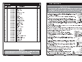
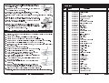
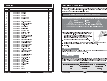
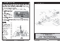
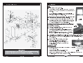
245 MM (10) BANDSAW & STAND MODEL No. CBS250 Part Part No. No. 6460135 6460200 OPERATING & MAINTENANCE INSTRUCTIONS 0604 Please read these instructions carefully before operating the tool CLARKE bandsaw. Before using the device, please read this manual thoroughly and carefully follow all instructions given. This is for your own safety and that of others around you, and is also to help you achieve a long and trouble free service from your new tool. Thank you for purchasing this CLARKE GUARANTEE This CLARKE product is guaranteed against faulty manufacture for a period of 12 months from the date of purchase. Please keep your receipt as proof of purchase. This guarantee is invalid if the product is found to have been abused or tampered with in any way, or not used for the purpose for which it was intended. Faulty goods should be returned to their place of purchase, no product can be returned to us without prior permission. This guarantee does not affect your statutory rights. PARTS & SERVICE TEL: 020 8988 7400 or e-mail as follows: PARTS: [email protected] SERVICE: [email protected] Please note that the details and specifications contained herein are correct at the time of going to print. However CLARKE International reserve the right to change specifications at any time without prior notice. Always consult the machines data plate -1- NOTES CONTENTS Guarantee ............................................................................. 1 Specifications ........................................................................ 2 Safety Precautions ............................................................. 3-4 Electrical Connections ......................................................... 5 Unpacking The Machine ..................................................... 6 Assembly ............................................................................. 7-8 Adjustments ...................................................................... 8-10 Changing Sawblade.......................................................... 11 Operating Instructions ................................................... 11-13 Maintenance ....................................................................... 13 Parts Diags ...................................................................... 14-15 Parts Lists ......................................................................... 16-18 SPECIFICATIONS Model: ..........................................................................CBS250 Part No: .......................................................................6460135 Power Rating .................................................................. 370w Fuse Rating .................................................................... 5amp Blade Speed .......................................................... 700 m/min Blade Length ............................................................. 1712mm Throat ...........................................................................245mm Max Cutting Depth @ 90°...........................................100mm Max Cutting Depth @ 45°.............................................75mm Table Size ........................................................... 340 x 335mm Table Height .............................................................. 1075mm Mitre Gauge Tilt ........................................................L60° R60° Dimensions.................................... D-450 xW-550 xH-1550mm -2- -19- SAFETY PRECAUTIONS Parts List Item 81 82 83 84 85 86 87 88 89 90 91 92 93 94 95 96 97 98 99 100 101 102 103 104 105 106 107 108 109 Part No QD250081 QD250082 QD250083 QD250084 QD250085 QD250086 QD250087 QD250088 QD250089 QD250090 QD250091 QD250092 QD250093 QD250094 QD250095 QD250096 QD250097 QD250098 QD250099 QD250100 QD250101 QD250102 QD250103 QD250104 QD250105 QD250106 QD250107 QD250108 QD250109 Description Housing Upper Slide Board Guide Lever Rack Cross Pan Hd Screw Cover Board Shaft Roll Pin Guide Piece Adjusting Knob Hex.Hd Lock Nut Cross Pan Hd Screw Wheel Lower Pulley Lower V-Ribbed Belts Hex.Nut Spring Washer Key Motor Pulley Int,Hd.Screw Power Cord Motor Cord Capacitor Motor Plate Mounting Motor Spring Washer Bearing Bolt Upper Hex.Hd Bolt Strong Draw WARNING: Qty 1 1 1 4 1 1 2 1 2 1 1 3 1 1 1 1 1 1 1 1 1 1 1 1 1 4 1 4 2 As with all machinery, there are certain hazards involved with their operation and use. Exercising respect and caution will considerably lessen the risk of personal injury. However, if normal safety precautions are overlooked or ignored, personal injury to the operator or damage to property, may result. 1. ALWAYS Learn the machines applications, limitations and the specific potential hazards peculiar to it. Read and become familiar with the entire operating manual. ALWAYS use a face or dust mask if operation is particularly dusty. 3. ALWAYS check for damage. Before using the machine, any 2. damaged part, should be checked to ensure that it will operate properly, and perform its intended function. Check for alignment of moving parts, breakage of parts, mountings, and any other condition that may affect the machines operation. Any damage should be properly repaired or the part replaced. If in doubt, DO NOT use the machine. Consult your local dealer. ALWAYS disconnect the tool/machine from the power supply before servicing and when changing accessories. 5. ALWAYS wear safety goggles, manufactured to the latest European Safety Standards. 4. Everyday eyeglasses do not have impact resistant lenses, they are not safety glasses. 6. ALWAYS keep work area clean. Cluttered areas and benches invite accidents. 7. ALWAYS ensure that adequate lighting is available. A minimum intensity of 300 lux should be provided. Ensure that lighting is placed so that you will not be working in your own shadow. 8. ALWAYS keep children away. All visitors should be kept a safe distance from the work area, especially whilst operating the machine. 9. ALWAYS maintain machine in top condition. Keep tools/machines 10. ALWAYS handle with extreme care do not carry the tool/machine clean for the best and safest performance. Follow maintenance instructions. by its electric cable, or yank the cable to disconnect it from the power supply . ALWAYS ensure the switch is off before plugging in to mains. Avoid accidental starting. 12. ALWAYS concentrate on the job in hand, no matter how trivial it may seem. Be aware that accidents are caused by carelessness due to familiarity. 13. ALWAYS keep your proper footing and balance at all 11. IMPORTANT: The use of parts other than CLARKE replacement parts may result in safety hazards, decreased tool performance and may invalidate your warranty. -18- times dont overreach. For best footing, wear rubber soled footwear. keep floor clear of oil, scrap wood, etc. -3- 14. ALWAYS wear proper apparel. loose clothing or jewellery may get caught in moving parts. wear protective hair covering to contain long hair. 15. ALWAYS use recommended accessories. the use of improper accessories could be hazardous. 16. ALWAYS remove plug from electrical outlet when adjusting, changing parts, or working on the machine. NEVER operate machine while under the influence of drugs, alcohol or any medication. 18. NEVER 17. leave machine running unattended. turn power off. Do not leave the machine until it comes to a complete stop. 19. NEVER force the machine. it will do a better and safer job at the rate for which it was designed. 20. NEVER use power tools in damp or wet locations or expose them to rain. Keep your work area well illuminated. do not use in explosive atmosphere (around paint, flammable liquids etc).Avoid dangerous environment. ADDITIONAL PRECAUTIONS FOR BANDSAWS 1. 2. 3. 4. 5. 6. ALWAYS check safety guards are in place and functioning correctly before switching the machine ON. ALWAYS use a push stick, especially on small workpieces. ALWAYS use the appropriate saw blade for the material being cut. DO NOT use the machine if the electric cable, plug or motor is in poor condition. DO NOT allow the ventilation slots in the motor to become blocked. DO NOT touch the blade immediately after use, when changing blade always allow time for it to cool. DO NOT use bent or cracked blades. 8. Replacement blades are available from your CLARKE dealer. 9. Replace table insert if slot has become enlarged. 10. When cutting wood, ensure all nails have been removed beforehand. Nails will damage the saw blade. 11. When cutting boards in upright position use a suitable push block to prevent kickbacks 12. When cutting round stock, use a suitable jig or fixture to keep the work from turning. 13. Ensure the blade is fully tightened and correctly adjusted before use. 14. Keep the mains cable well away from the machine and ensure an adequate electrical supply is close at hand so that the operation is not restricted by the length of the cable. 15. Switch the machine OFF immediately the task is completed. 7. Additionally, please keep these instructions in a safe place for future reference. -4- Parts List Item 41 42 43 44 45 46 47 48 49 50 51 52 53 54 55 56 57 58 59 60 61 62 63 64 65 66 67 68 69 70 71 72 73 74 75 76 77 78 79 80 Part No QD250041 QD250042 QD250043 QD250044 QD250045 QD250046 QD250047 QD250048 QD250049 QD250050 QD250051 QD250052 QD250053 QD250054 QD250055 QD250056 QD250057 QD250058 QD250059 QD250060 QD250061 QD250062 QD250063 QD250064 QD250065 QD250066 QD250067 QD250068 QD250069 QD250070 QD250071 QD250072 QD250073 QD250074 QD250075 QD250076 QD250077 QD250078 QD250079 QD250080 Description Hex.Hd Flange Nut Spacer Bushing Bush Cup Square Neck Bolt Cross Pan Hd Screw Hex.Hd Lock Nut Blade Guard Cup Square Neck Bolt Blade Trunnion Lower Washer Int.Hd.Screw Roller Guide Pilot Pin Thrust Bearing Shaft Bearing Idler Wheel Shaft Int,Hd.Screw Blade Fork Table Cup Square Neck Bolt Guide Piece Table Trunnion Upper Hex.Hd Bolt Handle Assembly Hex.Hd Bolt Hex Nut Hex.Hd Bolt Rip Fence Extrusion Roll Pin Partiality Piece Connet Set Baffle Bracket Stuck Piece Baffle` Spring Clamp Board Clamp Screw Fastening Shaft Seat Guide Upper Cross Pan Hd Screw -17- Qty 1 1 1 4 4 2 1 4 1 2 5 1 2 4 4 1 2 1 1 1 1 1 8 1 1 5 6 1 1 1 1 1 2 1 1 1 1 1 1 2 Parts List Item 1 2 3 4 5 6 7 8 9 10 11 12 13 14 15 16 17 18 19 20 21 22 23 24 25 26 27 28 29 30 31 32 33 34 35 36 37 38 39 40 ELECTRICAL CONNECTIONS Part No QD250001 QD250002 QD250003 QD250004 QD250005 QD250006 QD250007 QD250008 QD250009 QD250010 QD250011 QD250012 QD250013 QD250014 QD250015 QD250016 QD250017 QD250018 QD250019 QD250020 QD250021 QD250022 QD250023 QD250024 QD250025 QD250026 QD250027 QD250028 QD250029 QD250030 QD250031 QD250032 QD250033 QD250034 QD250035 QD250036 QD250037 QD250038 QD250039 QD250040 Description Slotted Insert Washer Housing Washer Door-Lower Housing + Nut Tongue Ext.LockWasher 6 Hex. Hd.Bolt M6x10 Door-Upper Saw Blade Retaining Ring Ball Bearing Upper Wheel Balance Collar Band Saw Tyre Bearing Upper Bolt Hex.Hd.Flange Nut Pin Guide Seat Brg Bolt Upper Hex.Hd.Flange Nut Guide Plate Assy Cross Pan.Hd.Screw Magnetic Switch Switch Plate Ext.Lock Washer Cross Pan Hd Screw Blade Tensioner Band Saw Frame Lamello Plug Black Adjust Handle Hex.Hd.Thin Nut Thread Bolt Washer Hex.Hd Bolt Hex.Hd Bolt Washer Nut Shaft Butterfly Spring -16- Qty 3 3 3 3 1 3 3 3 3 1 1 2 4 1 2 1 2 1 1 8 1 2 1 1 2 2 1 1 1 2 4 1 8 4 1 10 1 1 18 This product is fitted with a standard 13 amp, 230 volt (50Hz), BS 1363 plug, for connection to a standard, domestic electrical supply. Should the plug need changing at any time, ensure that a plug of identical specification is used. WARNING ! THIS APPLIANCE MUST BE EARTHED This machine must be wired up in accordance with the following colour code: BLUE NEUTRAL BROWN LIVE GREEN/YELLOW EARTH Connect the BLUE coloured cord to the plug terminal marked N Connect the BROWN coloured cord to the plug terminal marked L Connect the GREEN/YELLOW coloured cord to the plug terminal marked E If this appliance is fitted with a plug which is moulded on to the electric cable (i.e. non-rewireable) please note: 1. The plug must be thrown away if it is cut from the electric cable. There is a danger of electric shock if it is subsequently inserted into a socket outlet. 2. Never use the plug without the fuse cover fitted. 3. Should you wish to replace a detachable fuse carrier, ensure that the correct replacement is used (as indicated by marking or colour code). 4. Replacement fuse covers can be obtained from your local dealer or most electrical stockists. Fuse Rating The fuse in the plug must be replaced with one of the same rating (5 amps) and this replacement must be ASTA approved to BS1362. If in doubt, consult a qualified electrician. Do not attempt any electrical repairs yourself. Cable Extension Always use an approved cable extension suitable for the power rating of this tool (see specifications), the conductor size should also be at least the same size as that on the machine, or larger. When using a cable reel, always unwind the cable completely. IMPORTANT: If a cable extension is needed, it is essential to comply with the following data. Voltage Extension length 230v Up to 20m 230v From 20 to 50m -5- Cable section 2.5mm 4mm2 2 UNPACKING THE MACHINE When lifting etc, always seek assistance from an able bodied person wherever possible, also when seeking assistance, you must ensure that you explain carefully where and when to lift, the weight, where it is going to be placed etc, it is important you that you take complete charge and give clear and precise instructions. Lift only when the person you have asked, that he/she acknowledges full understanding. Parts Diagram To unpack the machine, proceed as follows:, 1. Move the case as close as possible to where the machine is to be sited. 2. Carefully open the case top, fold flaps back and secure using tape or string etc, see Fig. 1. 3. Remove all loose components etc, lay out carefully for checking off, see Fig. 2. 4. Carefully lift machine from the case and place with other components. 5. Before commencing with assembly, check for damage and or shortages etc, any damage or shortage should be reported to where the machine was purchased as soon as possible. Check List A. Machine 1off B. Aluminium Extrusion 1off C. Rip fence assembly 1off D. Short Cross Member 2off E. Long Cross Member 2off F. Mitre Gauge 1off long Beam 2off H. Short Beam 2off I. Bag (Screws) 1off J. Bag (Tools etc) 1off K. Rubber Foot 4off L.. Leg 4off M. T G. Fig. 1 able 1off N. Push Stick 1off Fig. 2 -6- PARTS & SERVICE TEL: 020 8988 7400 or e-mail as follows: PARTS: [email protected] SERVICE: [email protected] -15- Parts Diagram ASSEMBLY Stand Assemble sub assy x 2, see fig. 3. Parts required per assy, 2 legs (L), 1 short beam (H), 1 short cross member (D), and 8 short round head screws nuts and washers. Do not fully tighten until all screws and nuts are loosely fitted, once all screws are fitted, check assy for squareness and tighten nuts, do not overtighten. NOTE: beams and cross members fit inside legs, screws are fitted from the outside with washers and nuts on the inside. 1. 2. NOTE: long beams are fitted on top of short beams see Fig .4 For details. Hex head bolts are fitted from the top with washers and nuts on the underside. 3. 4. 5. Fig. 3 Connect sub assys together using 2 long cross members (E), 2 long beams (G), and 8 short round head screws nuts and washers, 8 short hex head bolts washers and nuts, DO NOT tighten until all screws etc are loosely fitted. Fig. 4 Turn assembly upside down and fit one rubber foot to each leg, by simply pushing on. Turn stand over onto its feet, ensure all screws, nuts and bolts are fully tightened, stand is secure and does not rock about. If stand does rock, loosen screws, nuts and bolts slightly, seat stand firmly and retighten all screws etc. With assistance, carefully lift the machine onto the stand, line up corner holes for securing, secure machine to stand using, 4 long hex head bolts, fitted from the top with washers and nuts on the underside, fit all four bolts before final tightening, do not overtighten. A Fit the table (M), onto trunnion, secure using four Hexagonal bolts (A) and shakeproof washers see Fig. 5, do not overtighten. Before switching ON, adjust the table so that the saw blade runs through the centre of the tables insert slot. Centering The Table IMPORTANT: The use of parts other than CLARKE replacement parts may result in safety hazards, decreased tool performance and may invalidate your warranty. Loosen the four screws (B) B securing the trunnion to the machine frame. Adjust the table so that the saw blade runs through the centre of the table insert. Tighten Fig. 5 the securing screws, and check saw blade still runs in the centre of the table insert, if not carry out the adjustment again. -14- Trunnion -7- Mitre Cutting Fit the aluminium profile with scale, to the front of the table using four bolts and washers supplied, ensure the cut out in the aluminium carrier is lined up with the T slot in the table. DO NOT overtighten the bolts, the aluminium profile is required to be removed when changing or fitting new sawblades. Setting The Table Square With The Sawblade A luminium Profile Most crosscut work, especially with small pieces is more easily controlled with the use of a mitre guide The mitre guide is also essential for accurate mitre and compound mitre cuts. The guide is graduated to 60O for both left and right Fig. 6 hand angles. Set the table square to the sawblade by loosening the knob, adjust the table so that the pointer lines up with the 0 position on the scale. (see Fig. 7). The table can be tilted to an angle of 45° to the sawblade. To tilt the table, loosen the knob, tilt the table top the required angle. The angle can be set by lining up the angle Pointer required on the scale with the pointer, it is recommended to check the correct angle setting, by making trial cuts in scrap pieces of wood. Always ensure the table is secured in position, by tightening the knob before attempting to use the saw. Knob Scale Fig. 7 MAINTENANCE Attach the rip fence by locating the guide pins into the groove on the aluminium profile, see Fig. 8, lower the hook over the back edge of the table and lock into position with locking lever. BEFORE CARRYING OUT ANY SERVICING OR MAINTENANCE, DISCONNECT THE MACHINE FROM THE POWER SUPPLY NOTE: when using the bandsaw with the table tilted, the rip fence must be fitted to the right of the sawblade. CHANGING TYRES Fig. 8 IMPORTANT Before plugging in and switching the machine ON, open the upper and lower band wheel doors. Fig. 7 Slowly rotate by hand, the upper band wheel in a clockwise direction only, observe the sawblade, which should run in the centre of both wheels, if the blade tracks off, carry out the tracking adjustment, if not your machine is ready for use. ADJUSTMENTS Before carrying out this adjustment, all six blade guides must first be backed off, 3 above and 3 below the table. Also remove the table insert. Eventually the rubber tyres on the bandsaw blade wheels will wear due to the constant contact of the sharp teeth of the blade. Lift the edge of the tyre with a small screwdriver and the tyre can be worked off the wheel easily. We recommend that both tyres are changed at the same time. BLADE GUIDES Blade guides should be inspected regularly for wear or chipping, and replaced if necessary. BEARINGS Tracking WARNING For your protection, ALWAYS use a push stick, this can easily be replaced, your fingers cannot Handwheel Open the upper and lower doors Release the handwheel lock, (see Fig. 9), by turning it anticlockwise. Whilst slowly rotating the upper blade wheel clockwise, slowly turn the handwheel at the rear of the machine, (see Fig. 9), observe the sawblade, if it tracks in the desired direction, continue to turn the handwheel in the same direction until the blade runs in the centre of the blade wheels, if the blade -8- All bearings used in the construction of your bandsaw and its motor are sealed and lubricated for life. CLEANING Accumulated dust and chips should be removed from inside the bandsaw frequently. Open the doors, of the upper and lower blade wheel housings, use a soft brush and/or vacuum cleaner to remove sawdust, DO NOT use compressed air. At the end of every work session, clean sawdust away from the motor vents. Fig. 9 Lock -13- Use both hands to feed the workpiece in to the blade. The work must be held flat on the table at all times to prevent binding of the blade. Use a steady even pressure just sufficient to keep the blade cutting. Always use a rip fence or mitre guide where possible to eliminate any sideways slip of the work. This is most important when the table is tilted to an angle. Always plan your work ahead. The tradesmans rule is measure twice, cut once. It is best to finish a cut in one continuous operation, but frequent backtracking may be necessary. Turn off the motor and allow the blade to come to a complete stop before backing the workpiece away. Remember that the blade removes material during the cut. This gap created by the blade is called the kerf, and must be allowed for when cutting to exact sizes. Plan your cut so that the kerf is the scrap side of the lines you wish to cut. If necessary, allow a little more for finish sanding. Rip Sawing This term refers to the cutting of the timber with the grain, rather than across the grain. You can rip wood freehand to a previously drawn line, but best results are obtained by using the rip fence. If the table is set level, set the rip fence to the left hand side of the blade (FIg.17), allowing you to use your right hand to hold the work firmly against the fence. The width of cut indicator on the front of the work table shows the distance between the blade and the edge of the timber. tracks in the wrong direction, turn the handwheel in opposite direction. When tracking is achieved, lock the handwheel by turningthe lock clockwise. Lower Blade Wheel Under normal circumstances, the bottom blade wheel does not need adjusting, it is factory set and should never alter. If however the blade tracks off centre and all the previous A adjustments have been carried out correctly, proceed to adjust as follows. The bottom blade wheel is adjustable in all directions, so extreme caution should be used when making any adjustments, if at all. It should only ever be necessary to make any changes on the two vertical adjusting screws A see Fig. 10. Fig. 10 To carry out this adjustment, proceed as follows. Loosen both locknuts on adjusting screws Slowly rotate the upper blade wheel in a clockwise direction, observe the sawblade whilst doing so. Loosen the top screw A. Sawblade Machine Frame Tighten Loosen A, Shaft approx one flat. a n d A Shaft tighten the bottom screw A. Fig. 17 If the sawblade tracks Tighten in the desired direction, Loosen continue with the adjustment, When cutting a bevel rip, with the table tilted at any angle up to 45O, set the rip fence to the right hand side of the blade (Fig. 18), if the if not, loosen the bottom screw Lower Blade Wheel and tighten the top screw. Fig. 11 Continue to make further adjustments in width of the workpiece allows it. the same way until the blade runs in the centre of both blade wheels, it may be With the fence on the downhill side of the table, it necessary to readjust the top wheel. NOTE: when making this adjustment, turn the adjusting screws one flat at a time and observe the blade movement, once the blade runs in the centre of the blade wheels, tighten all locknuts. will help support the work against slip. The width of cut indicator shows the distance between the blade and the rip fence. Blade Cross Cutting Fig. 18 This term refers to cutting timber at right angles to the grain. This type of cut can also be made freehand, but the mitre guide is used to ensure accurate results. The mitre guide can be adjusted to a 45O angle to produce mitre cuts, or with the table tilted as well, compound mitre cuts. Make sure the work is held firmly against the table and against the face of the mitre guide. Be careful to keep your fingers away from the blade, particularly at the end of the cut. -12- Guide Adjustment Remove the table. Assuming the blade is running in the centre of both blade wheels, continue to adjust the blade guides as follows. Loosen all guides, and back them off clear of the blade. Rotate the upper blade wheel and observe the blade again, if the blade now runs in the centre of the blade wheels, continue to adjust the blade guides. If not adjust the tracking. Upper Blade Guides Loosen grub screw A and move rear guide up to the back of the sawblade, until -9- it almost touches leaving a gap of no less than 0.5mm. Tighten Changing the Sawblade. Upper Blade Guides the grub screw. Ensure the machine is switched OFF, and isolated from the main electrical supply by removing the plug from the 13amp socket. Loosen grub screw B and move the side guide up to the sawblade, again until it is within 0.5mm. Tighten grub screw. Repeat with the other side guide by loosening grub screw C. NOTE: the side guides must not cover more than two thirds of the blade, see Fig. 12, otherwise the guides will come into contact with the sawblade teeth. If the guides do cover more than two thirds of the sawblade, this can be reduced by carrying out the following adjustment. Loosen grub screw D Fig.13 B A 0.5mm C Fig. 12 and move the assembly in required direction, when correct position is achieved, tighten the grub screw. Lower Blade Guides Loosen the thumb Remove the rip fence. Carefully remove the sawblade, and store safely. Clean the machine, using a soft brush and vacuum cleaner. Remove the aluminium Profile. Remove the table insert. Open the upper and lower doors. Open the sawblade guard. Loosen the tension on the sawblade by turning the handwheel on the top of the bandsaw in an anticlockwise direction. Fit the new sawblade in reverse order, ensure the blade is installed so that it runs in the correct direction. NOTE: before tensioning the blade, ensure it is located in all the blade guides correctly. Slowly tension the blade by turning the handwheel on top of the machine in a D screw, (see Fig. 14), and adjust the rear blade guide as with the upper rear guide. 0.5mm Front View Fig. 13 Loosen the grub screws, (see Fig.12), A 0.5mm & B, and Side View OPERATION Thumbscrew adjust the side guides as with the upper side guides. NOTE: if the guides cover more than two thirds of the blade, adjust as follows. Loosen nut at the rear of the guide assembly, (see Fig. 15), Before commencing work, ensure the work area is clean and tidy, and the machine table is clear of tools etc. adjust the assembly as required, ensure the guides remain square to the sawblade, when satisfied the guides are adjusted correctly, tighten the nut, taking care not to move the guide assy. NOTE: when carrying out this adjustment with either the upper assy or the lower assy, it is important before commencing to back the rear guide off first, and readjust again once the assembly is locked in place. Front View Fig. 14 B Plan work carefully and set the machine up accordingly before plugging into the main electrical supply. Cutting can be carried out using several methods, i.e. freehand, rip fence for parallel cutting, mitre guide, push blocks, etc. A When all guide adjustments are complete, refit the table etc. Nut Rear View Fig. 15 -10- clockwise direction, at the same time, slowly rotate by hand, the upper blade wheel, also in a clockwise direction, whilst doing this, observe the blade, it should run in the centre of both blade wheels. Only tension sufficiently to ensure the blade is taught and does not slip on the blade wheels. If the blade runs off centre, adjust the tracking as follows. Under normal circumstances this should not be necessary. The upper blade guide should always be set as close as practical to the workpiece, see Fig. 16. Not only does this provide the best safety for the operator, but it also brings the blade guides closer to the work giving more accurate results and easier control. to adjust the height, turn the adjusting knob on the right hand side of the upper wheel housing, anticlockwise to lower and clockwise to raise the guide assembly. continue to turn the knob until the required height is reached. -11- Fig. 16