Download Apogee Mini-Series FireWire User`s guide
Transcript
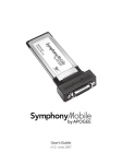
Mini-Series FireWire Expansion Card
User’s Guide
V1.0 - March 2007
Mini-Series FireWire Expansion Card
User’s Guide
V1.0 - March 2007
Mini FireWire card – User’s Guide
APOGEE ELECTRONICS
Warnings
FCC warning
This equipment has been tested and found to comply with the limits for a Class A digital device, pursuant to Part
15 of the FCC rules. These limits are designed to provide reasonable protection against harmful interference when
operated in a commercial environment. This equipment generates, uses, and can radiate radio frequency energy
and, if not installed and used in accordance with the instruction manual, may cause harmful interference to radio
communications. Operation of this equipment in a residential area is likely to cause harmful interference, in which
case the user will be required to take whatever measures necessary to correct the interference at his own expense.
Copyright Notice
The Apogee Mini FireWire card is a computer-based device, and as such contains and uses software in ROMs.
This software, and all related documentation, including this User’s Guide contain proprietary information which is
protected by copyright laws. All rights are reserved. No part of the software and its related documentation may be
copied, transferred, or modified. You may not modify, adapt, translate, lease, distribute, resell for profit or create derivative works based on the software and its related documentation or any part thereof without prior written consent
from Apogee Electronics Corporation, U.S.A.
ii
Mini FireWire card – User’s Guide
APOGEE ELECTRONICS
Declarations of Conformity
This device complies with Part 15 of the FCC Rules. Operation is subject to the following two conditions:
(1) This device may not cause harmful interference
(2) This device must accept any interference received, including interference that may cause undesired operation.
This equipment has been tested and found to comply with the limits of a Class B digital device, pursuant to Part
15 of the FCC Rules. These limits are designed to provide reasonable protection against harmful inteference in a
residential installation. This equipment generates, uses and can radiate radio frequency energy and, if not installed
and used in accordance with the instructions, may cause harmful interference to radio communications. If this
equipment does cause harmful interference to radio or television reception, which can be determined by turning
the equipment off and on, the user is encouraged to try to correct the interference by one or more of the following
measures:
1. Re-orient or relocate the receiving antenna.
2. Increase the separation between the equipment and receiver.
3. Connect the equipment into an outlet on a different circuit from that to which the receiver is connected.
4. Consult the dealer or an experienced radio/TV technician for help.
NOTE: The use of non-shielded cable with this equipment is prohibited.
CAUTION: Changes or modifications not expressly approved by the manufacturer responsible for compliance
could void the user’s authority to operate the equipment.
Apogee Electronics Corporation, 1715 Berkeley St, Santa Monica, CA 90404.
Betty Bennett, CEO.
Industry Canada Notice
This Class B digital apparatus meets all requirements of the Canadian Interference-Causing Equipment Regulations. Cet appareil numérique de la classe B respecte toutes les exigences du Règlement sur le matérial brouilleur
du Canada.
Declaration of Conformity – CE
Apogee Electronics Corporation hereby declares that the product, the Mini FireWire card, to which this declaration
relates, is in material conformity with the following standards or other normative documents:
• EN50081-1/EN55022; 1995
• EN50082-1/IEC 801-2, 3, 4; 1992
following the provisions of:
• 73/23/EEC – Low Voltage Directive
• 89/336/EEC – EMC Directive
Declaration of Conformity – Japan
Apogee Electronics Corporation hereby declares that the Mini FireWire card, to which this declaration relates, is in
material conformity with the VCCI Class A standard.
Declaration of Conformity – Australia
Apogee Electronics Corporation hereby declares that the Mini FireWire card is in material conformity with AN/NZS
standard requirements.
iii
Mini FireWire card – User’s Guide
APOGEE ELECTRONICS
Registration and Warranty Information
Be sure to register your Mini FireWire card, either by filling in the enclosed Registration Card or by completing the
on-line registration form at our Web site: http://www.apogeedigital.com/support/. If you do so, Apogee can contact
you with any update information. As enhancements and upgrades are developed, you will be contacted at the
registration address. Firmware updates are free for the first year of ownership unless otherwise stated. Please
address any inquiries to your dealer or directly to Apogee at:
APOGEE ELECTRONICS CORPORATION,
1715 Berkeley St. Santa Monica CA, 90404 • TEL: (310) 584-9394, FAX: (310) 584-9385
email: [email protected]. Web: http://www.apogeedigital.com/
APOGEE ELECTRONICS CORPORATION warrants this product to be free of defects in material and
manufacture under normal use for a period of 12 months. The term of this warranty begins on the date of sale to
the purchaser. Units returned for warranty repair to Apogee or an authorized Apogee warranty repair facility will
be repaired or replaced at the manufacturer’s option, free of charge.
ALL UNITS RETURNED TO APOGEE OR AN AUTHORIZED APOGEE REPAIR FACILITY MUST BE
PREPAID, INSURED AND PROPERLY PACKAGED, PREFERABLY IN THEIR ORIGINAL BOX. Apogee
reserves the right to change or improve design at any time without prior notification. Design changes are
not implemented retroactively, and the incorporation of design changes into future units does not imply the
availability of an upgrade to existing units.
This warranty is void if Apogee determines, in its sole business judgment, the defect to be the result of abuse,
neglect, alteration or attempted repair by unauthorized personnel.
The warranties set forth above are in lieu of all other warranties, expressed or implied, and Apogee specifically
disclaims any and all implied warranty of merchantability or of fitness for a particular purpose. The buyer
acknowledges and agrees that in no event shall the company be held liable for any special, indirect, incidental or
consequential damages, or for injury, loss or damage sustained by any person or property, that may result from
this product failing to operate correctly at any time.
USA: Some states do not allow for the exclusion or limitation of implied warranties or liability for incidental or
consequential damage, so the above exclusion may not apply to you. This warranty gives you specific legal
rights, and you may have other rights which vary from state to state.
Service Information
The Mini FireWire card contains no user-serviceable components: refer to qualified service personnel for repair or
upgrade. Your warranty will be voided if you tamper with the internal components. If you have any questions with
regard to the above, please contact Apogee.
In the event your Mini FireWire card needs to be upgraded or repaired, it is necessary to contact Apogee prior
to shipping, and a Return Materials Authorization (RMA) number will be assigned. This number will serve as a
reference for you and helps facilitate and expedite the return process. Apogee requires that shipments be prepaid and insured — unless otherwise authorized in advance.
IMPORTANT: ANY SHIPMENT THAT IS NOT PRE-PAID OR IS SENT WITHOUT AN RMA NUMBER WILL
NOT BE ACCEPTED.
iv
Mini FireWire card – User’s Guide
APOGEE ELECTRONICS
OWNER’S RECORD
The serial number is located on the upper side of the card. We suggest you record the
serial number in the space provided below. Refer to it whenever you call an authorized
Apogee Electronics repair facility or the manufacturer. Please be sure to return your completed warranty card immediately!
Mini FireWire card Serial No._____________________________________________
Purchase Date__________________________________________________________
Dealer_________________________________________________________________
Phone_________________________________________________________________
Address________________________________________________________________
CAUTION:
Any changes or modifications not expressly approved by APOGEE ELECTRONICS
CORPORATION could void your authority to operate this equipment under the FCC rules.
Please register this unit by filling in the included registration card, or registering online at
http://www.apogeedigital.com/support/register.php Please read this manual – if you call for
technical support, we’ll assume that you have. There will be a quiz.
v
User’s Guide
Contents
Introduction 2
Requirements 2
Host Interface 2
Windows XP 2
OS X 2
Overview 2
New Features 3
Sample Rate Range 3
Multiple Units 3
Before Starting 3
Working with Apple OS X 4
Installing the driver 4
Setting up AMS 4
Matching sample rates 4
Working with Apple OS X 5
Maestro 5
Multiple Host interfaces 5
Working with Windows XP 6-14
Installing the Driver 6
Apogee 1394 Audio Control Panel 9
Devices Window 10
Input Channels Window 10
Output Channels Window 11
Synchronization Window 11
Synchronization Window 12
Settings Window 13
Stream buffer depth 13
ASIO buffer depth 13
WDM sound buffer depth 13
General Notes 14
Troubleshooting 14
Configuring Audio Applications for use with Mini FireWire equipped Apogee Interfaces 15-17
Configuring Steinberg Nuendo on Windows XP 15
Configuring Windows Media Player on Windows XP 16
Configuring Apple Logic on OS X 16
Configuring Apple Logic on OS X (continued) 17
Configuring iTunes on OS X. 17
Installing the Mini FireWire Card 18-20
Mini FireWire card – User’s Guide
APOGEE ELECTRONICS
Introduction
The Mini FireWire card brings FireWire 400 conectivity to the Apogee MiniMe and MiniDAC
digital audio interfaces. The Mini FireWire card is compatible with both Apple OS X and
Windows XP computers.
Requirements
Host Interface
Apogee MiniMe or MiniDAC interface
Windows XP
OS:
Hardware :
OS X
OS :
Hardware :
Windows XP SP 2 (Windows 2000 or earlier not supported)
1.5 gig or greater processor
At least 512 megs RAM
FW 400 or FW 800 FireWire ports using a Texas Instruments or Lucent chipset
OS X 10.4.7 or higher
1 GHz or greater
At least 512 MB RAM
Overview
The following steps must be completed before using your Mini FireWire card. A detailed
description of each step may be found further in this User’s Guide.
• If you’re installing a Mini FW card in a MiniMe or MiniDAC, please consult pages 18-20.
• Before connecting your Mini FireWire equipped Apogee interface to the FireWire port of
your Mac, load the included software CD and install the FireWire driver appropriate for your
OS.
• Configure your audio application as specified on pages 15-17
2
Mini FireWire card – User’s Guide
APOGEE ELECTRONICS
New Features
Sample Rate Range
The MiniMe now interfaces with Mac and PC computers at sample rates up to 96kHz, while the
MiniDAC interfaces with computers at sample rates up to 192kHz.
Multiple Units
Thanks to Mini FireWire’s clocking scheme, it’s possible to connect multiple units to both Apple
OS X and Windows XP computers.
Before Starting
MiniMe - MiniDAC Front Panels
New front panels are not provided for MiniMe/MiniDACs equipped with a Mini FireWire card, thus:
On a MiniMe, the front panel MIX knob combines signal from the analog input (DIR) and
the Mini Firewire card signal return (USB).
On a MiniDAC, the Input Select setting USB is used to choose input from the Mini Firewire
card. Format conversion functions with the Mini Firewire card in the same manner as USB,
described on pages 15-16 of the MiniDAC User’s Guide.
4-pin FireWire cables/ports
The Mini FireWire card uses power from the FireWire bus, thus 4-pin FireWire cables and ports
(which do not include power connections) may not be used with the card.
3
Mini FireWire card – User’s Guide
APOGEE ELECTRONICS
Working with Apple OS X
Installing the driver
Load the included Apogee Software CD, and double click on the ApogeeSoftware installer icon.
Follow the on-screen instructions.
Setting up AMS
• Connect the Mini FireWire card to your Mac.
• Open the Audio Midi Setup (or AMS) utility, found on an OSX Macintosh here: Applications/Utilities/
Audio Midi Setup.
• Click on the Properties For drop-down menu and select Apogee FireWire (xxxx) (the serial number of
your card appears in parentheses).
Matching sample rates
• The sample rate of the host interface must be matched manually to the sample rate of the connected
computer:
• On the MiniMe, ensure that the front panel Sample Rate selection is set to the same sample rate as
indicated in AMS.
• On the MiniDAC, if Input Select is set to any option but USB, ensure that the digital input sample rate
(to which the MiniDAC will lock) is the same rate as that indicated in AMS.
• If Input Select is set to USB, the MiniDAC will automatically follow the sample rate selected in AMS;
ensure that other digital inputs are at the same rate.
• Certain audio applications such as Apple Logic Pro and other DAWs will set the AMS sample rate to the
sample rate of currently opened sessions. Thus, when opening new sessions, re-verify that the session
sample rate is the same as the host interface rate.
4
Mini FireWire card – User’s Guide
APOGEE ELECTRONICS
Working with Apple OS X
Maestro
A Mini FireWire-equipped host interface is recognized in Maestro, Apogee’s multi-function software utility.
The following functions are available:
Input level – the input level of the MiniMe/MiniDAC is displayed adjacent to the leftmost faders of
Maestro’s Mixer page.
Software output level – the output level of software playing out to the MiniMe/MiniDAC is displayed
adjacent to the DAW Return faders of Maestro’s Mixer page.
MiniFW lock – On Maestro’s Settings page, the Lock checkbox indicates that the MiniFW card is
receiving a proper clock and is connected properly.
UV22HR (MiniMe only) – On Maestro’s Mixer page, checking the UV22HR box enables UV22HR
processing on the FireWire output (to the audio software program). For more information concerning
UV22HR, please see page 12 of the Mini-Me User’s Guide.
Multiple Host interfaces
It is possible to connect multiple MiniMes/MiniDACs to a Mac via Mini FireWire cards installed in each
unit by using the Aggregate Device function in AMS. For more details see “Combining multiple audio
devices to work as one device” in Audio Midi Setup Help.
5
Mini FireWire card – User’s Guide
APOGEE ELECTRONICS
Working with Windows XP
Installing the Driver
Load the included Apogee Software CD, and unzip the Minifw_Windows_XP_driver folder.
Before starting the setup.exe driver installation program, disconnect the Mini FireWire card from
the computer. You will be instructed at which point during the driver installation process to connect the
Mini FireWire card. If you have multiple units, be sure to connect them all when instructed to do so.
1 Double click on the setup.exe.
2 As noted onscreen, disconnect the Mini FWequipped interface,then click on Next.
If a previous version of the driver was
installed, this window will be preceded by an
uninstallation procedure.
6
Mini FireWire card – User’s Guide
APOGEE ELECTRONICS
Working with Windows XP
3 Determine the Destination for the installer,
and click Next. We recommend that you install
the driver in the default location.
4 Click Next.
2 Click Continue Anyway. Disregard this message from Microsoft.
7
Mini FireWire card – User’s Guide
APOGEE ELECTRONICS
Working with Windows XP
3 Now connect the Mini FW-equipped interface,
and click Next.
It may be necessary to wait for the New Hardware Found notification pop-up to appear
before clicking Next.
4 Click Continue Anyway.
5 During the installation process, you should
see these three Found New Hardware Notification pop-ups: Apogee FireWire, Apogee
FireWire WDM Audio, and Your new hardware is installed and ready to use.
8
Mini FireWire card – User’s Guide
APOGEE ELECTRONICS
Working with Windows XP
6 To verify that the driver is correctly installed,
double click on the Safely Remove Hardware icon in the Notification area (usually in
the lower right hand corner of your computer
screen).
If both Apogee FireWire and Apogee
FireWire WDM Audio devices are not displayed, the installation has failed. Go to Add
or Remove Programs in the control panel,
uninstall the driver, power cycle the computer
and Apogee host interface, and re-install the
driver.
Apogee 1394 Audio Control Panel
Once correct driver installation has been verified, open the Apogee 1394 Audio control panel by double
clicking on the Apogee 1394 Audio icon found in the Windows XP control panel. While discovering the
functionality of the control panel as described below, try a few control panel operations, such as switching
sample rates, to verify proper communication between the control panel and the Apogee host interface.
9
Mini FireWire card – User’s Guide
APOGEE ELECTRONICS
Working with Windows XP
The Apogee 1394 Audio control panel consists of the following 5 windows accessed by clicking on their
names in the left hand column of the control panel : Devices, Input Channels, Output Channels,
Synchronization and Settings.
Devices Window
In the Devices window, Apogee FireWire
should be displayed under Device name, and
a unique serial number is displayed under Serial number. If multiple host interfaces have
been installed, they should all appear simultaneously. Press Edit Device Name to edit the
Device name.
Input Channels Window
In the Input Channels window, it’s possible to
edit the input Channel names for the devices
connected.
10
Mini FireWire card – User’s Guide
APOGEE ELECTRONICS
Working with Windows XP
Output Channels Window
In the Output Channels window, it’s possible
to edit the output Channel names for the devices connected.
Synchronization Window
In the Synchronization window, synchronization parameters for each device should be set
as described on the next page.
11
Mini FireWire card – User’s Guide
APOGEE ELECTRONICS
Working with Windows XP
Synchronization Window
Sampling Rate - The sample rate of the FireWire driver is set with this drop-down menu. Ensure that the
sample rate of the audio application matches the setting made here.
The sample rate of the host interface must be matched manually to the sample rate of the connected
computer:
• On the MiniMe, ensure that the front panel Sample Rate selection is set to the same sample rate
as indicated in AMS.
• On the MiniDAC, if Input Select is set to any option but USB, ensure that the digital input sample
rate (to which the MiniDAC will lock) is the same rate as that indicated in AMS.
• If Input Select is set to USB, the MiniDAC will automatically follow the sample rate selected in
AMS; ensure that other digital inputs are at the same rate.
Synchronization Settings - Settings available here and in the Device Synchronization Mode window
should be set as shown below, regardless of the host interface clock setting. Clock settings for an MiniSeries-equipped host interface should be made from the interface’s front panel.
1 Under Ck Master, check Apogee Mini
FireWire.
2 Select the Apogee Mini FireWire device and
click Change Synchronization Mode.
3 Check Digital Input (Internal) and click OK.
4 Click Apply.
To configure multiple Mini FireWire-equipped interfaces:
• Before connecting the interfaces to the computer, install the driver as described on pages 6-9.
• Make the Synchronization Settings described above for each interface.
12
Mini FireWire card – User’s Guide
APOGEE ELECTRONICS
Working with Windows XP
Settings Window
Three buffer settings are provided in this window, Stream buffer depth, ASIO buffer depth, and WDM
sound buffer depth. Found below are a few general guidelines for setting buffer depths - please note
that the right setting depends on the speed of your computer’s processor and the amount of processing
needed for a particular session in your audio application (as determined by the number of I/O, the number
of DSP plug-ins, soft synths, etc.).
• Lower buffer depths result in lower latency from input to output, but can result in buffer overruns which
cause clicks and pops. Buffer overruns occur when the computer’s CPU runs out of processing power
and cannot provide data quickly enough to the driver. If clicks and pops do occur, either the buffer
depth must be increased to give the CPU more time, or the CPU’s load must be reduced by removing
plug-ins, tracks or other DSP.
• Higher buffer settings result in higher latency but allow the use of more DSP (plug-ins, soft synths)
without clicks and pops.
• During the recording phase of a session, it’s best to compromise DSP usage in order to minimize
latency, so the performers being recorded are not disturbed by latency. To eliminate latency in
performer’s cue mix, use Apogee’s Firemix Software Mixer.
• During the mixing phase of a session, latency is in most cases not an issue, thus it’s possible to
increase buffer depths so more DSP may be used without clicks and pops.
Stream buffer depth
This is an expert setting, and should be left at 2.0 ms in most cases. If your processor is exceptionally
fast, you may try lowering the buffer depth for lower latency. If the Apogee host interface is locking
intermittently to FireWire, Stream buffer depth should be increased..
ASIO buffer depth
This setting controls buffer depth when using the Mini FireWire card with ASIO-compatible applications
(Steinberg Nuendo-Cubase, Sonar 4 (not 3), Samplitute, and others.
WDM sound buffer depth
This setting controls buffer depth when using the Mini FireWire card with applications that employ WDM.
13
Mini FireWire card – User’s Guide
APOGEE ELECTRONICS
Working with Windows XP
General Notes
If you change the Apogee Mini FireWire hardware connected to your computer in any way (i.e. you add
interfaces or change Mini FireWire cards), it’s necessary to uninstall and re-install the Windows XP driver.
Troubleshooting
Symptom – When the driver instructs me “To finish the installation connect your device to this computer
and turn it on”, I connect the device but nothing happens; the Apogee hardware is not recognized.
Solution – This indicates some sort of hardware problem:
• Test the host interface on another computer if possible
• Verify the chipset of the computer FireWire connections. We have had the most reliable operation with
Texas Instruments or Lucent chipsets.
Symptom – I’m getting clicks and pops in my audio software.
Solution – Go to the Apogee 1394 Audio control panel’s Settings window and increase the buffer setting
sizes.
14
Mini FireWire card – User’s Guide
APOGEE ELECTRONICS
Configuring Audio Applications for use with
Mini FireWire equipped Apogee Interfaces
In general, configuring the “major” audio applications (such as Apple Logic, Steinberg Nuendo or
Cubase,MOTU Digital Performer or Cakewalk Sonar 4) consists of identifying a Device Setup window in
the app and selecting the Apogee host interface as the hardware device providing I/O. On the other hand,
configuring “utility” audio applications such as Windows Media Player (on Windows XP) or iTunes (on OS
X) consists of selecting the Apogee host interface in an operating system control panel. The following four
configuration examples are given below:
Configuring Steinberg Nuendo on Windows XP
Configuring Windows Media Player on Windows XP
Configuring Apple Logic on OS X
Configuring iTunes on OS X.
From these examples it should be possible to deduce configuration details for the specific audio
application you’re using. Please consult operating instructions for the audio application.
Configuring Steinberg Nuendo on Windows XP
1 After verifying proper operation of the Mini FireWire
card with the Apogee 1394 Audio control panel, open
Nuendo.
2 Under Nuendo’s Devices drop-down menu, select
Device Setup then VST Multitrack.Set ASIO Driver to
Apogee FireWire ASIO Driver.
3 It’s possible to access the Apogee 1394 Audio control
panel by clicking on the Control Panel button.
4 Under Nuendo’s Devices drop-down menu, select VST
Connections.
5 Create Input and Output busses as needed and assign
ASIO Device Ports to the newly created busses.
15
Mini FireWire card – User’s Guide
APOGEE ELECTRONICS
Configuring Audio Applications for use with
Mini FireWire equipped Apogee Interfaces
Configuring Windows Media Player on Windows XP
1 From the Windows XP control panel, open the Sounds and
Audio Devices control panel.
2 Select the Audio tab.
3 Set Sound playback and Sound recording Default devices to
Bco#ApogeeFireWire LineOut and LineIn, as depicted below.
4 Open Windows Media Player and….play!
Configuring Apple Logic on OS X
1 Connect the Apogee interface and open Apple
Logic.
2 In Logic, select Audio > Audio Hardware &
Drivers to open the Core Audio driver page.
3 First click on the Drivers tab, then the Core Audio
tab.
4 Check the Enabled checkbox (click OK when the
“Reboot Logic” message is displayed”).
5 Select Apogee FireWire (xxxx) in the Driver field
(click Try (Re)Launch when the “Reboot Logic”
message is displayed”).
6 Set I/O Buffer Size to 512; once the proper
operation of the Apogee hardware is verified, this
value may be reduced to lower latency.
7 Though it’s not specific to Apogee hardware, you’ll
probably want to check the 24 Bit Recording as well
as Software Monitoring check boxes.
16
Mini FireWire card – User’s Guide
APOGEE ELECTRONICS
Configuring Audio Applications for use with
Mini FireWire equipped Apogee Interfaces
Configuring Apple Logic on OS X (continued)
8 In Logic’s Track Mixer, set the inputs and outputs of Audio objects to the desired hardware I/O
channels, as shown below.
Configuring iTunes on OS X.
1 Open the Audio Midi Setup ultility, found
on an OS X Macintosh here: Applications >
Utilities > Audio MIDI Setup.
2 Set Default Input, Default Output, and
System Output to Apogee FireWire (xxxx)
The Mini FireWire serial number is displayed in
parentheses.
3 In Audio Midi Setup, set Properties For to
Apogee FireWire (xxxx), set Clock Source to
Apogee FireWire (xxxx) Synch and Format
to 44100.0Hz.
4 Open iTunes, and play!
17
Mini FireWire card – User’s Guide
APOGEE ELECTRONICS
Installing the Mini FireWire Card
Included in the Mini FireWire Update Kit:
Additional tools needed
1 Mini FireWire card
1 back panel
1/8” Allen wrench
1 Apogee Software CD
1 Mini FireWire User’s Guide
(MiniMe only) 1 EPROM
small Phillips head screwdriver
small flat blade screwdriver
needle nose pliers
1. Remove the 2 Allen screws found in the top corners of the
front panel
Figure 1
2. Remove the rear panel fasteners:
Figure 2
Figure 2A
On a MiniMe remove:
4 Allen screws found in the rear panel corners
2 Phillips head screws holding the AES XLR connector
1 knurled washer holding the headphone connector
2 Phillips head screws holding each input XLR connector
On a MiniDAC remove:
4 Allen screws found in the rear panel corners
1 Phillips head screw holding the Coax/Optical connector
2 captive nuts holding the AES connector
1 knurled washer holding the Line Out connector
4 Phillips head screws holding each output XLR connector
18
Mini FireWire card – User’s Guide
APOGEE ELECTRONICS
Installing the Mini FireWire Card
3. Lift off the host interface’s top and pull back the host
interface’s rear panel
The MiniMe/MiniDAC serial number is affixed to the original
rear panel. Be sure to record the serial number before
installing the new panel.
Figure 3
4. If installing the Mini FireWire card in a MiniMe, replace the
EPROM chip with the EPROM chip that comes with your Mini-FireWire card
• Locate the EPROM depicted in
figure 4, and note the orientation of
the semi-circular notch found at one
end of the chip.
• Using a small flat blade
screwdriver, gently pry out the
EPROM, and set it aside. To use
MiniMe with a USB card, you will
need to save this EPROM.
• Orient the semi-circular notch
of the new EPROM in the same
direction as the old, and place the
new EPROM on top of the EPROM
socket.
• Once you have verified that the
EPROM’s 8 legs are properly
inserted, press firmly on the top of
the EPROM to seat it in the socket.
Figure 4
Figure 4A
19
Mini FireWire card – User’s Guide
APOGEE ELECTRONICS
Installing the Mini FireWire Card
5. Installing the Mini FireWire card
• If a USB card is already installed, remove the two USB card mounting
screws, and set them aside for a later step. Lift the USB card straight up
and out of the host interface.
• Line up the dual row of connector pins found under the Mini FireWire
card with the socket found on the host interface motherboard. Once you
have verifed that the pins are correctly inserted, press on the top of the
Mini FireWire card until the pins are completely
seated in the socket. (Re)-install the two card
mounting screws.
Figure 5
Figure 5A
6. Installing the new rear panel, re-installing the top
• Slide the new rear panel on, ensuring that the FireWire connector
protrudes through the rear panel.
• Re-install all rear panel screws.
• Re-install the top cover and re-install all Allen screws.
Figure 6
Figure 6A
20
Mini-Series FireWire card USER’S GUIDE - v1.0 - March 2007


