1
MaXiO
System Manual
INDEX
1. Introduction.................................................................................................................................. 3
1.1 About this manual .................................................................................................................. 3
1.2 What’s in the Box? ................................................................................................................. 4
1.3 Key Features........................................................................................................................... 4
1.3.1 MaXiO PCI host card........................................................................................................ 4
1.3.2 EX8000 2U Rack .............................................................................................................. 4
1.3.3 MaXiO 032 breakout box ................................................................................................. 5
2.1 MaXiO PCI host card ............................................................................................................. 6
2.1.1 E.D.I connector ................................................................................................................. 6
2.1.2 M.D.I connector ................................................................................................................ 6
2.2 EX8000................................................................................................................................... 7
2.2.1 Front Panel Input Channel Section ................................................................................... 7
2.2.2 Front Panel Power Section................................................................................................ 8
2.2.3 Back Panel Power Section ................................................................................................ 8
2.2.4 Front Panel Clock & Control Section ............................................................................... 8
2.2.5 Back Panel Clock Section................................................................................................. 9
2.2.6 Analog Outputs & Inserts ................................................................................................. 9
2.2.7 Digital I/O (Back Panel) ................................................................................................. 10
2.3 M.D.I breakout cable ( for MaXiO XD only) ...................................................................... 11
2.3.1 Word Clock I/O............................................................................................................... 11
2.3.2 MIDI I/O ......................................................................................................................... 11
2.3.3 S/PDIF Digital I/O .......................................................................................................... 11
2.4 MaXiO 032 breakout box..................................................................................................... 12
2.4.1 Front Panel Input Channel Section ................................................................................. 12
2.4.2 MIDI signal LEDs & Phantom power ........................................................................... 13
2.4.3 Analog Outputs ............................................................................................................... 13
2.4.4 Digital I/O ....................................................................................................................... 14
2.4.5 MIDI I/O and M.D.I connector....................................................................................... 14
3. Hardware Installation ............................................................................................................... 15
3.1 Minimum System Requirements .......................................................................................... 15
3.2 Installation of MaXiO PCI host card.................................................................................... 15
3.3 EX8000 connection .............................................................................................................. 17
3.4 MaXiO 032 connection ........................................................................................................ 18
1
MaXiO
System Manual
4. Driver Installation...................................................................................................................... 19
5. MaXiO Control Panel................................................................................................................ 26
5.1 Pull Down Menu .................................................................................................................. 26
5.2 Input Section......................................................................................................................... 27
5.2.1 Input signal path block diagram...................................................................................... 29
5.3 Output Section...................................................................................................................... 30
5.3.1 Master Section ................................................................................................................ 31
5.3.2 Master & Output signal path block diagram................................................................... 32
5.4 MaXiO display section......................................................................................................... 32
5.4.1 MaXiO State ................................................................................................................... 33
5.4.2 System Clock .................................................................................................................. 33
5.4.3 I/O Config ....................................................................................................................... 34
5.5 The EX8000 control panel ................................................................................................... 36
6. Applications Setup ..................................................................................................................... 39
6.1 Windows Multimedia setup.................................................................................................. 39
6.2 Cubase and Nuendo.............................................................................................................. 40
6.3 Cakewalk SONAR ............................................................................................................... 41
6.4 Wavelab................................................................................................................................ 43
6.5 Tracktion .............................................................................................................................. 44
7. DirectWIRE 3.0.......................................................................................................................... 45
7.1 What is DirectWIRE?........................................................................................................... 45
7.2 DirectWIRE Panel................................................................................................................ 45
7.3 DirectWIRE examples.......................................................................................................... 46
8. Technical Specifications ............................................................................................................ 49
END USER WARRANTY ............................................................................................................ 52
V2 JULY 2005
2
MaXiO
System Manual
1. Introduction
Thank you for choosing the ESI MaXiO.
The MaXiO System Manual covers the MaXiO PCI host card and all extensions such as the
EX8000 rack unit and the MaXiO 032 breakout box.
MaXiO XD is a complete 24-bit / 192 kHz recording system designed to handle up to 32 input
channels and 32 output channels simultaneously.
The basic MaXiO XD system consists of the MaXiO PCI host card and one EX8000, a 2U-rack
space unit with 8 analog input channels, 8 analog output channels, ADAT, and digital I/O. The PCI
card is equipped with four FireWire-like E.D.I (ESI Digital Interface) ports, each capable of
individually supporting one breakout box with E.D.I connection like the EX8000.
There is also a single M.D.I (Multiple Digital Interface) multichannel connector on the PCI host
card for future expansion. This gives the MaXiO XD system 32 input and 32 output channel
capability on one single interface card. By default, the M.D.I connection of the MaXiO PCI host
card provides coaxial S/PDIF I/O, Word Clock I/O and a 1 in / 1 out MIDI interface.
Another member of the MaXiO series, the MaXiO 032’s 4 ADAT inputs and 4 ADAT outputs
provide 32 input and 32 output channels, via a single PCI card and its breakout box. Now you can
connect your computer to up to 4 ADAT compatible devices and use them simultaneously for multi
track recording.
There is more: next to S/PDIF I/O and a full 16 channel MIDI interface MaXiO 032 provides a high
quality stereo analog input with microphone preamps (48V phantom power support), a high end
123dB[A] ADC, and 120dB[A] DAC. This turns MaXiO 032 into a reference audio hardware
providing audio quality at a level that has not been achieved before in this price range.
The MaXiO 032 can be expanded via its E.D.I (ESI Digital Interface) connectors into a full MaXiO
XD system by adding one or several EX8000 units.
On PC systems, MaXiO systems are equipped with ESI's unique and powerful EWDM driver for
perfect compatibility with Windows XP and 2000, offering ultra low-latency performance with all
popular digital audio software applications including Nuendo, Cubase, Gigastudio, Cakewalk,
Sonar, Logic, Samplitude and Sequoia.
1.1 About this manual
The MaXiO XD system and MaXiO 032 are very flexible and provides a huge number of features
and options. In order to use it to its full capabilities, you need to understand the usage and concepts.
We know that most users do not like to read long manuals such as this (we don’t like it either ...) –
because of that, we have tried to keep this manual as short as possible. Please take your time to read
it completely.
3
MaXiO
System Manual
1.2 What’s in the Box?
Your MaXiO XD package contains the following:
·
·
·
·
·
·
·
·
·
MaXiO PCI host card
Driver CD with UAT bundle software
Tracktion Software CD
MaXiO System Manual (this document)
M.D.I breakout cable
standard IEEE1394 connection cable
EX8000 2U rack
power cable for EX8000
EX8000 User's Guide
Your MaXiO 032 package contains the following:
·
·
·
·
·
MaXiO PCI host card
Driver CD with UAT bundle software
Tracktion Software CD
MaXiO System Manual (this document)
The M.D.I connection cable (between MaXiO PCI host card and MaXiO 032 breakout
box)
1.3 Key Features
1.3.1 MaXiO PCI host card
·
·
·
·
·
·
·
·
·
·
·
32bit PCI Interface with PCI Bus-Mastering support
PCI slot compatibility – designed to suit +3.3V and/or +5V PCI slots
24bit /192 kHz audio interface
maximum 32 input and 32 output channels
Full Duplex – simultaneous record / playback
4 E.D.I & 1 M.D.I connectors
Coaxial digital I/O support up to 24-bit / 192 kHz (built on M.D.I breakout cable for
MaXiO XD only)
Word Clock I/O: Fs / 256*Fs, BNC connector (built on M.D.I breakout cable for
MaXiO XD only)
1 in / 1 out, 16 channel MIDI (built on M.D.I breakout cable for MaXiO XD only)
Supports EWDM driver: MME/WDM, DirectSound, ASIO 2.0, GSIF
Windows ® XP/2000 compatible
1.3.2 EX8000 2U Rack
·
·
4
E.D.I Connector
High-end quality 24-bit / 192 kHz ADC with 123dB(a) dynamic range
MaXiO
System Manual
·
·
·
·
·
·
·
·
·
·
·
·
High-end quality 24-bit / 192 kHz DAC with 120dB(a) dynamic range
8 balanced analog inputs with combo (XLR / TRS) connectors featuring ESI’s newly
developed 'XD-PRE' high precision & ultra low noise (-135.5dBu) microphone
preamplifier on each analog input channel with support for +48V phantom power
Mic/Line selection switch and gain control for each analog input channel
8 inserts (one for each analog input channel) with 1/4" connectors
8 balanced analog outputs with XLR connectors (+4dBu)
8 balanced/unbalanced analog outputs with TRS connectors (-10dBV)
Headphone amplifier with volume control
8 channel digital I/O in AES/EBU (XLR connectors) and coaxial S/PDIF (RCA
connectors) format, supporting up to 24-bit / 192 kHz
8 channel ADAT optical digital I/O with S/MUX support
10 step LED level meters on front panel for all channels (input and output)
Supported sample rates: 44.1, 48, 88.2, 96, 176.4 and 192 kHz
Word Clock input: Fs / 256*Fs (via BNC connector)
1.3.3 MaXiO 032 breakout box
·
·
·
·
·
·
·
·
·
·
·
·
·
M.D.I connector
High-end quality 24-bit / 192 kHz ADC with 123dB(a) dynamic range
High-end quality 24-bit / 192 kHz DAC with 120dB(a) dynamic range
2 balanced analog inputs with combo (XLR / TRS) connectors featuring ESI’s newlydeveloped 'XD-PRE' high precision & ultra low noise (-135.5dBu) microphone
preamplifier on each analog input channel with support for +48V phantom power
Mic/Line/Hi-Z selection switch and gain control for each analog input channel
2 balanced analog outputs with XLR connectors (+4dBu)
2 balanced/unbalanced analog outputs with TRS connectors (-10dBV)
Headphone amplifier with volume control
2 channel digital I/O in coaxial S/PDIF (RCA connectors) format,
supports up to 24-bit / 192 kHz resolution/sample rate
32 channel ADAT optical digital I/O
Supported sample rates: 44.1, 48, 88.2, 96, 176.4 and 192 kHz
Word Clock input and output: Fs / 256*Fs (via BNC connector)
1 in / 1 out, 16 channel MIDI
5
MaXiO
System Manual
2.1 MaXiO PCI host card
2.1.1 E.D.I connector
E.D.I is ESI’s exclusive digital audio transfer protocol that delivers an 8 channel audio stream (with
up to 24-bit / 192 kHz). E.D.I uses an IEEE1394/FireWire cable for the connection of E.D.I
compatible devices like EX8000 to the MaXiO PCI host card. The PCI host card has 4 E.D.I
connectors that allow you to connect 4 devices such as EX8000 simultaneously, providing 32 input
and 32 output channels.
2.1.2 M.D.I connector
The M.D.I connection can handle 32 digital input and 32 digital output streams for the extension of
MaXiO 032 breakout box.
* In the basic MaXiO XD system, the MaXiO PCI card connects to the special M.D.I breakout
cable (described below).
6
MaXiO
System Manual
2.2 EX8000
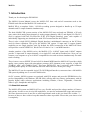
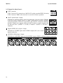
2.2.1 Front Panel Input Channel Section
1
Analog Balanced XLR / TRS (Combo) Input Connector
EX8000 provides 8 combo connectors (XLR and 1/4" TRS) on
the front panel that are used as balanced analog inputs for line
level signals and microphone connection (via XLR).
2
4
2
Microphone Input Selection Switch
Every input channel can be used for line level or microphone
signals. When this switch is enabled, a microphone can be
connected via XLR. In this case phantom power is supplied
(when enabled, check 7 ). When the switch is not enabled, the
XLR and TRS inputs are used for balanced line level signals.
3
Input Gain Control
Controls the amount gain applied to the input signal from the
XLR or TRS connector of specific channel. Microphone signals
can be amplified with 48dB maximum, line level signals with up
to 30dB.
4
1
3
Analog Input / Output Level Meter
The two level meters indicate the signal level for the analog inputs and outputs. The level meter
on the left shows the input signal; the level meter on the right shows the output signal of the
corresponding channel. A range from 0dB to 60dB in 10 dB-steps is displayed.
7
MaXiO
System Manual
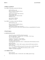
2.2.2 Front Panel Power Section
Power Indicator LED
5
5
6
Power Switch
7
Phantom Power Switch
6
+48V DC phantom power (for balanced condenser microphones) will be
supplied via every XLR input connector when this button is enabled.
Note that this affects only those input channels that are set to receive
microphone signals (check 2 ).
7
Before you turn on the phantom power switch, you must make sure to connect your
microphones to the XLR inputs (with balanced cables).
·
After you have turned on the phantom power switch, you should not connect or
disconnect a microphone to any of the input connectors.
·
!
CAUTION
2.2.3 Back Panel Power Section
22
22
AC IN
EX8000 needs external AC power. It supports 100~240V AC (free voltage). There
is a spare fuse (5X20mm Glass Fuse) below the connector.
2.2.4 Front Panel Clock & Control Section
9
Clock Source Indicator
Displays the current clock source of EX8000:
- Internal: EX8000 uses its internal clock.
- External: EX8000 works with the clock from the Word Clock input.
- Digital In: EX8000 works with the clock supplied from the AES/EBU,
S/PDIF or ADAT input.
- E.D.I:
EX8000 works with the clock from the MaXiO PCI host
card.
10
12
Clock Select Button 1
When EX8000 is working in stand alone mode, you can choose the
clock source with this button (Internal, External, Digital In). This
function is not available when EX8000 is connected to the MaXiO PCI
host card.
12
11
Clock Frequency Indicator
Displays the current sample rate of EX8000.
11
9
10
Clock Select Button 2
When EX8000 is working in stand alone mode, you can choose the sample rate with this button
(44.1 ~ 192 kHz). This function is not available when EX8000 is connected to the MaXiO PCI
host card.
8
MaXiO
System Manual
2.2.5 Back Panel Clock Section
21
Word Clock Input
The Word Clock input allows you to synchronize EX8000 with other devices. When
EX8000 is connected to a Word Clock source, EX8000 will synchronize to it.
2.2.6 Analog Outputs & Inserts
8
Headphone
You can monitor the playback signal from output 1, 2 through the headphone
output. The output level can be adjusted with the volume pot.
14
Inserts
The inserts allow you to use the microphone preamps of EX8000 for incoming signals, and then
run the signal through external hardware processors or effects before the AD-converter digitizes
the signal. In order to use the inserts, you typically need an "insertcable" with a 1/4" TRS connector on one and two 1/4" mono
connectors on the two other ends. Here is a description of the insert
connector:
- Tip: return signal (input from effect processor)
- Ring: send (output to effect processor)
- Sleeve: common ground
15
Analog Balanced TRS Output Connectors
EX8000 has 8 balanced/unbalanced analog outputs (-10dBV) with TRS connectors.
16
Analog Balanced XLR Output Connectors
EX8000 has 8 balanced analog outputs (+4dBu) with XLR connectors.
9
MaXiO
System Manual
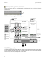
2.2.7 Digital I/O (Back Panel)
17
E.D.I Connector
E.D.I Connector IN: connection to MaXiO PCI (with a standard IEEE1394 cable).
E.D.I Connector THRU: this connector is reserved for future expansion.
18
ADAT Optical Input / Output
EX8000 has 8 channel ADAT optical I/O connectors. You can connect EX8000
to devices such as digital mixers or ADAT multichannel recorders equipped
with optical ADAT connectors. One ADAT cable transfers 8 channels with max.
48 kHz. EX8000 also supports different S/MUX modes to transfer signals with
96 kHz and above (S/MUX 2: 96 kHz, 4 channels / S/MUX 4: 192 kHz, 2
channels).
19
Digital S/PDIF (RCA) Input / Output
EX8000 has 4 S/PDIF inputs and 4 S/PDIF outputs (RCA) for coaxial
digital connection.
20
AES/EBU (XLR) Input / Output
EX8000 has 4 AES/EBU inputs and 4 AES/EBU outputs (XLR) for balanced digital connection.
10
MaXiO
System Manual
2.3 M.D.I breakout cable ( for MaXiO XD only)
2.3.1 Word Clock I/O
This connector allows you to synchronise the MaXiO PCI host card via Word Clock (BNC) with
other audio devices. You can synchronise other devices via the Word Clock output (FS / 256xFS)
and you can also synchronise the MaXiO PCI host card to other devices via the Word Clock input.
This is controlled via the MaXiO XD Control Panel software.
2.3.2 MIDI I/O
The MaXiO XD system also provides a MIDI interface with 1 input and 1 output (16 channels) via
the M.D.I breakout cable.
2.3.3 S/PDIF Digital I/O
The MaXiO PCI host card also provides coaxial digital S/PDIF I/O connection via the M.D.I
breakout cable. The supported sample rates are: 32 kHz, 44.1 kHz, 48 kHz, 64 kHz, 88.2 kHz, 96
kHz. The supported resolution is 24-bit (internal 32-bit).
11
MaXiO
System Manual
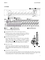
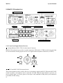
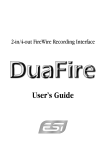
2.4 MaXiO 032 breakout box
6-7
1-5
1. Front Channel Section
MIDI indicator & Phontom power
8
9 MIDI I/O
11 8 x ADAT Digital I/O
12-13
Headphone
S/PDIF & Word Clock
10 M.D.I connector
14
13 Analog outputs (XLR & 1/4“)
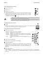
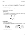
2.4.1 Front Panel Input Channel Section
1
Analog Balanced XLR / TRS (Combo) Input Connector
MaXiO 032 breakout box provides 2 combo connectors (XLR and 1/4" TRS) on the front panel that
are used as balanced analog inputs for line level signals and microphone connection (via XLR).
1
4
2
3
5
2
3
Hi-Z and MIC/ LINE Selection Switch
These input channels can be used for line level, microphone signals and Hi-Z. When the MIC/LINE
switch is pushed, a microphone can be connected via XLR. When the Hi-Z button is pressed, you
can use analog input as electric guitar or bass input. Only unbalanced TRS phone jack connection
is available for this setting.
12
MaXiO
4
System Manual
Input Gain Control
Controls the amount gain applied to the input signal from the XLR or TRS connector of specific
channel. Microphone signals can be amplified with 48dB maximum, line level signals with up to
30dB.
5
Analog Input Level Meter LEDs
The meters indicate the signal level for the analog inputs.
2.4.2 MIDI signal LEDs & Phantom power
6
7
MIDI signal LEDs.
Phantom Power Switch
+48V DC phantom power (for balanced condenser microphones) will be supplied via every
XLR input connector when this button is enabled. Note that this affects only those input
channels that are set to receive microphone signals (check 2 ).
6
7
2.4.3 Analog Outputs
8
Headphone output with gain control
You can monitor the playback signal from output 1, 2 through the headphone output. The output
level can be adjusted with the volume pot.
8
14
14
Analog 2 XLR and 2 1/4” TRS outputs
13
MaXiO
System Manual
2.4.4 Digital I/O
MaXiO 032 has 32 channel ADAT optical I/O connectors. You can connect MaXiO 032 to
devices such as 4 ADAT compatible devices. One ADAT cable transfers 8 channels with max. 48
kHz.
11
11
12
12
13
Digital S/PDIF (RCA) Input / Output
MaXiO 032 has stereo S/PDIF inputs and outputs (RCA) for coaxial digital connection.
13
Word Clock Input / Output
This connector allows you to synchronise the MaXiO PCI host card via Word Clock (BNC) with
other audio devices. You can synchronise other devices via the Word Clock output (FS / 256xFS)
and you can also synchronise the MaXiO PCI host card to other devices via the Word Clock input.
This is controlled via the MaXiO XD Control Panel software.
2.4.5 MIDI I/O and M.D.I connector
9
MIDI I/O
MaXiO 032 breakout box provides a MIDI interface with 1 input and 1 output (16 channels
9
10
10
M.D.I connector
It’s where you can connect MaXiO PCI host card via M.D.I connection cable.
The M.D.I connection can handle 32 digital input and 32 digital output streams for the extension of
MaXiO 032 breakout box.
14
MaXiO
System Manual
3. Hardware Installation
3.1 Minimum System Requirements
·
·
·
·
·
·
·
Intel Pentium 4 or equivalent and compatible CPU
Motherboard with chipset supporting the Intel Pentium 4 (e.g.: Intel 845, 865 and
newer or equivalent VIA Chipset)
at least 512MB of RAM
one available PCI slot
Microsoft Windows 2000/XP operating system
hard disk supporting UDMA 66/100 and 7200rpm
active monitor speakers or monitor speakers with powered amplifier
Please check section 5.4.3 I/O Config – CH. Limit in this manual to find the best setup of your
MaXiO system that perfectly matches your specific system configuration.
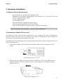
3.2 Installation of MaXiO PCI host card
The MaXiO PCI host card and other components in your computer can easily be damaged by
electrical shocks. You need to use an anti-static device that can discharge the static electricity of
your body to avoid potential static damage to the cards.
The MaXiO PCI card is packaged in an anti static plastic pouch. Do not open the pouch until you’re
ready to install the card.
1. Turn off the computer power and remove the power cable from your computer’s power
supply.
disconnecting the power cord
2. Remove the cover. Make sure that you have an available PCI slot in your motherboard to
install the MaXiO PCI host card. Please refer to your computer’s user manual on how to
remove the cover.
removing the computer cover
15
MaXiO
System Manual
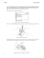
To avoid possible static shock to the computer parts, discharge it by touching the computer
case or something grounded. We recommend you to use an anti-static device such as an antistatic wrist band. When you need to hold the MaXiO PCI host card, please hold it on the
edge of the card. Do not grab the card by touching the board.
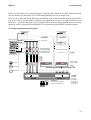
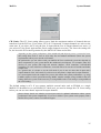
3. Find an empty PCI slot on the motherboard.
typical PC motherboard slot configuration
If there is a faceplate blocking the empty slot, please remove it using the proper screwdriver.
removing the PCI slot faceplate
Put the MaXiO PCI host card into the slot and make sure it is placed in correctly. Insert the
card into the slot and then tighten the screw. Then you can close the computer case.
MaXiO PCI host card installed in a PCI slot
16
MaXiO
System Manual
4. You can finish the installation of the PCI host card by connecting the M.D.I breakout cable
to the M.D.I port (if you use no other M.D.I compatible device like the MaXiO 032 breakout
box).
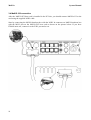
3.3 EX8000 connection
After the MaXiO PCI host card is installed in the PCI slot, you should connect EX8000 to the card
using the supplied standard IEEE1394/FireWire cable.
Start by connecting the EX8000 with the E.D.I In connector on EX8000 with the first E.D.I port on
the MaXiO PCI host card as shown on the picture below. If you have several EX8000 units, connect
the second unit to the second E.D.I port and so on.
17
MaXiO
System Manual
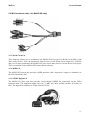
3.4 MaXiO 032 connection
After the MaXiO PCI host card is installed in the PCI slot, you should connect MaXiO 032 to the
card using the supplied M.D.I cable.
Start by connecting the MaXiO breakout box with the M.D.I In connector on MaXiO breakout box
with the M.D.I port on the MaXiO PCI host card as shown on the picture below. If you have
EX8000 units too, connect it to the E.D.I port and so on.
18
MaXiO
System Manual
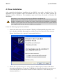
4. Driver Installation
After completing the hardware installation of your MaXiO, you need to install its driver. The
installation steps in Windows 2000 and Windows XP vary, but they are similar between the
different versions of Windows. The installation steps shown below are based on Windows XP
installation.
!
CAUTION
Depending on your system, you may need your Windows installation CD.
Because of the driver characteristic, the MaXiO driver installs several devices. In some cases
Windows continuously tries to reboot your system. Unless the driver installation is completely
finished, e.g. the system does not detect any new devices, DO NOT reboot the system. Restart
your computer only after the drivers for all devices are installed.
Follow the following steps for the installation:
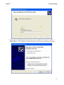
1. Turn on the main power of your computer. Windows will automatically detect that a new
device has been installed and prompt you with the Found New Hardware Wizard screen.
Choose Install from a list or specific location and click Next >.
2. Choose Search for the best driver in these locations and specify the location of the driver.
Insert the provided driver CD into the CD-ROM drive and select Include this location in the
search and click Browse to find the accurate location of the driver. Then confirm your
selection with Next >.
19
MaXiO
System Manual
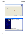
3. During installation, you will be prompted with a message warning that the driver software
has not passed Windows Logo testing. Select Continue Anyway and proceed with the
installation. The driver is completely tested and verified by ESI, and safe to use.
4. The MaXiO EWDM Controller driver will be installed.
20
MaXiO
System Manual
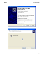
5. Keep going to install follow the instructions on screen. Other devices (such as MaXiO
EWDM Wave-1) are installed now after each other. Check the screen shots for reference.
21
MaXiO
22
System Manual
MaXiO
System Manual
23
MaXiO
System Manual
When the system asks you to restart the computer (which happens on some computers), just
ignore the requests and continue to install. When all the necessary device drivers are
installed and the system is not asking you to install any further drivers, restart the
computer manually.
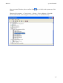
6. Now you can check if the installation was successful.
24
MaXiO
After you restart Windows, please confirm if the
task bar.
System Manual
icon is visible in the system tray of the
Then go to My computer -> Control panel -> System -> Device Manager. Check the
devices under Sound, video and game controllers, if they are installed correctly.
25
MaXiO
System Manual
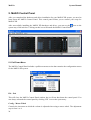
5. MaXiO Control Panel
After you completed the hardware and driver installation for your MaXiO XD system, you need to
learn about the MaXiO Control Panel. This control panel allows you to control your setup for
MaXiO XD.
icon on the
After successfully installing the MaXiO XD hardware and driver, you can see the
system tray of the task bar. Clicking on this icon will launch the MaXiO Control Panel.
5.1 Pull Down Menu
The MaXiO Control Panel includes a pull down menu section that contains the configuration menus
for the MaXiO XD system.
File - Exit
This will close the MaXiO Control Panel window but it will not shut down the control panel. You
can always relaunch the control panel by clicking ‘ESI’ icon on the system tray.
Config – Mouse Wheel
Controls the increment at which the volume is adjusted when using a mouse wheel. The adjustment
step is from 1 to 8.
26
MaXiO
System Manual
Config – Latency
Here you can choose between different buffer sizes. There are 2 different sections: First buffer sizes
from 128 samples (3 milliseconds with 44.1 kHz) to 2048 samples (48 milliseconds with 44.1 kHz).
Secondly there are the ultra latency settings: buffer sizes from 96 Samples (2,5 milliseconds) to 32
Samples (0.75 milliseconds). A lower latency is achieved by selecting a smaller buffer size.
Typically a lower latency is good when working with software synthesizers or when you process
audio signals from the audio inputs in realtime with your audio software. A smaller latency value
will however also cause more system load.
For most recording applications on a typical PC, select buffer sizes between 64 and 512. For a
typical faster Pentium 4 system, 128 or 256 are good values. Buffer sizes of 32, 48, 1024 and 2048
are normally used only in special circumstances, e.g. 32 is reserved for very fast and reliable ASIO
driver working environments only. The factory default is 512 to provide a basic level of
compatibility to different systems.
Config – Factory Default
Returns all MaXiO Control Panel configuration settings to the factory default.
Config - Always On Top
Enables to display the MaXiO Control Panel always over other windows. If this is not selected, the
active windows of other applications will be shown over the MaXiO Control Panel.
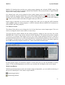
5.2 Input Section
Port Selection
E.D.I Device Detection
Input Level Meter
MME Channel Mapper
M.D.I Analog Input
M.D.I S/PDIF Input
Input Monitor Buttons
The left section of the control panel windows shows the status and the control features for the input
channels. The main part of the display is the Input Level Meter for each channel. Above that the
Control Panel displays automatically if an external device such as the EX8000 is connected to one
of the E.D.I ports. Below the level meter, controls for each specific channel are provided (MME
device selection for recording, M.D.I input channel selection). A detailed explanation for each
section starting from top follows. Note that the input monitoring section is explained under 5.3.1
Master Section.
27
MaXiO
System Manual
Port Selection
The 32 input channels of the MaXiO XD system are grouped into 4 sections (ports) with 8 input
channels each. For each group of 8 channels (each port), you can select either the corresponding
E.D.I input (1 to 4) or the signals from the M.D.I connector by clicking on the IN PORTx label.
When you change the selection of a port, the same change will be made for the output channels.
When a port is set to M.D.I, the corresponding input channels from a device connected to the M.D.I
port like the MaXiO 032 breakout box are use. The specific E.D.I port cannot be used at the same
time. For example, if you select M.D.I for port 2 (channels 9-16), you can use input channels 9-16
from device like the MaXiO 032 connected to the M.D.I port of the MaXiO PCI host card but you
cannot use the E.D.I port 2 (e.g. if an EX8000 is connected to it).
E.D.I Device Detection
The MaXiO Control Panel will automatically detect any device connected to a E.D.I port. For
example, if EX8000 is connected to E.D.I port 1, you can control its features by double clicking on
the blue EX8000 text. A separate window will be opened.
MME Channel Mapper
The MaXiO XD system driver provides the MME device MaXiO Stereo Wave (SPDIF/PCM) that
can be used for recording and playback of stereo signals. The MME Channel Mapper section in the
MaXiO Control Panel allows you to assign the I/O channels that will be used by this MME device.
You have two options to select the I/O channel for the MME device. You can click on the arrow
button ( ) and then select the channel in the menu that will appear or you can click on the
individual icon ( ) under each channel.
The MME Channel Mapper has no influence on the multichannel MME device MaXiO Multi Wave
or on the ASIO driver ASIO 2.0 -MaXiO.
M.D.I Analog and S/PDIF Input
The MaXiO PCI host card provides support for two analog input channels and a digital S/PDIF
input made available via a device connected to the M.D.I port of the card. For example, the MaXiO
032 breakout box provides both analog input channels and a digital S/PDIF input. The M.D.I
breakout cable that is supplied with the basic MaXiO XD system provides a digital S/PDIF input
but no analog input channels.
The two analog input channels and the two input channels from the digital S/PDIF input can be
assigned to any channel pair of the 32 input channels provided by the MaXiO PCI host card. The
button assigns the two analog input channels to the specific channel pair, the button assigns the
two S/PDIF input channels instead. Alternatively you can assign the channels via the arrow buttons
( ) on the left side and the menu that will appear when you click on it.
28
MaXiO
System Manual
Please note that when you select the analog or S/PDIF input channels, the input signals from that
specific channel pair from the E.D.I or M.D.I multichannel ports are no longer used.
Please keep in mind that the M.D.I analog and S/PDIF input selection buttons should not be used if
you do not want to use the S/PDIF or analog input signals from the device or cable connected to the
M.D.I port – use them only when you are using the M.D.I breakout cable (S/PDIF inputs, no analog
inputs) or a M.D.I extension like the MaXiO 032 breakout box (both S/PDIF and analog inputs).
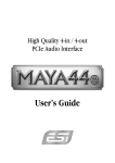
5.2.1 Input signal path block diagram
E.D.I Connector #2
E.D.I Connector #1
E.D.I 1
E.D.I 2
IN PORT1
M.D.I Connector
1/2
3/4
5/6
7/8
IN PORT2
8 ch. audio stream
M.D.I [1/4]
M.D.I [2/4]
M.D.I [3/4]
M.D.I [4/4]
S/PDIF IN
ANALOG IN
S
X X
A
X X
S
S
A
A A
Mono MIX
X X
S
Onboard S/PDIF Input
Ch. selection (CH3/4)
same structure
as port 1
Onboard Analog Input
Ch. selection (CH1/2)
z REC DMA
1/2/3/4/5/6/7/8 ch.
Total 32ch DMA
at (max.) 192kHz
z REC DMA
9/10/11/12/13/14/15/16 ch.
To PC
Monitor ON
X X Monitor OFF
1/2
3/4
5/6
7/8
9/10
11/12
13/14
Internal 64ch 32bit Digital Mixer
MASTER OUT
To Selected output Channel,
analog out and S/PDIF out
15/16
IN PORT3
IN PORT4
OUT PORT 1
OUT PORT 2
OUT PORT 3
OUT PORT 4
29
MaXiO
System Manual
5.3 Output Section
Port Selection
Master Output Select
E.D.I Device Detection
Master Fader
Output Level Meter
MME Channel Mapper
M.D.I Analog Output
M.D.I S/PDIF Output
Output Monitor Buttons
Master to Analog &
S/PDIF Button
The right section of the control panel windows shows the status and the control features for the
output channels. The layout is very similar to the input section (described in the previous section).
The main part of the display is the Output Level Meter for each channel. Above that the Control
Panel displays automatically if an external device such as the EX8000 is connected to one of the
E.D.I ports. Below the level meter, controls for each specific channel are provided (MME device
selection for playback, M.D.I output channel selection). A detailed explanation for each section
starting from top follows.
Port Selection
The 32 output channels of the MaXiO XD system are grouped into 4 sections (ports) with 8 output
channels each. For each group of 8 channels (each port), you can select either the corresponding
E.D.I output (1 to 4) or the channels of the M.D.I port by clicking on the OUT PORTx label. When
you change the selection of a port, the same change will be made for the input channels.
E.D.I Device Detection
The MaXiO Control Panel will automatically detect any device connected to a E.D.I port. For
example, if EX8000 is connected to E.D.I port 1, you can control its features by double clicking on
the blue EX8000 text. A separate window will be opened.
MME Channel Mapper
The MaXiO XD system driver provides the MME device MaXiO Stereo Wave (SPDIF/PCM) that
can be used for recording and playback of stereo signals. The MME Channel Mapper section in the
MaXiO Control Panel allows you to assign the I/O channels that will be used by this MME device.
You have two options to select the I/O channel for the MME device. You can click on the arrow
button ( ) and then select the channel in the menu that will appear or you can click on the
individual icon ( ) under each channel.
The MME Channel Mapper has no influence on the multichannel MME device MaXiO Multi Wave
or on the ASIO driver ASIO 2.0 -MaXiO.
M.D.I Analog and S/PDIF Output
The MaXiO PCI host card provides support for two analog output channels and a digital S/PDIF
output made available via a device connected to the M.D.I port of the card. For example, the
30
MaXiO
System Manual
MaXiO 032 breakout box provides two analog output channels and a digital S/PDIF output. The
M.D.I breakout cable that is supplied with the basic MaXiO XD system provides a digital S/PDIF
output but no analog output channels.
One channel pair each can be assigned to these analog outputs and to that S/PDIF output. The
button assigns the specific channel pair to the analog output channels, the button assigns the the
channel pair to the S/PDIF output. Alternatively you can assign the channels via the arrow buttons
( ) on the left side and the menu that will appear when you click on it.
Please keep in mind that you can use these outputs only when you are using the M.D.I breakout
cable (S/PDIF output, no analog outputs) or a M.D.I extension like the MaXiO 032 breakout box
(both S/PDIF and analog outputs).
5.3.1 Master Section
The Master Fader allows you to change the level of one final stereo mixed output signal. The level
can be set using the mouse, mouse wheel, or cursor keys.
You can select the output channel for the master signal by clicking on the red arrow left of the
MASTER label. Under it, the current selection will be displayed. The picture below shows channel
1/2 of Port 3 as selection. This output receives a mix of the 8 input channels from Port 1 and the 8
playback channels from Port 2 (check the description of the monitoring buttons in the next section
for reference). On this picture, the Control Panel is also configured to send out the master signal to
the S/PDIF and Analog outputs of the device / cable connected to the M.D.I port.
In many typical setups you would use output 1/2 of the first port (e.g. the first EX8000) as master
output. Via the monitoring buttons (see below) you can then mix all signals to this stereo output.
Monitoring Buttons
With the monitoring buttons under each channel (input and playback), you can enable monitoring of
the specific channel pair via the master output channel.
: Monitoring disabled
: Monitoring enabled
31
MaXiO
System Manual
: Monitoring enabled, signal will be mixed to mono
With the circle on the right, you can disable/enable monitoring for all input (or playback) channels
simultaneously.
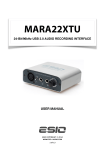
5.3.2 Master & Output signal path block diagram
E.D.I Connector #2
E.D.I Connector #1
E.D.I 1
E.D.I 2
OUT PORT1
1/2
` 3/4
5/6
7/8
OUT PORT2
8 ch. audio stream
same structure
as port 1
M.D.I Connector
M.D.I [1/4]
Master Output
Ch. selection
(CH1/2)
M.D.I [2/4]
X X
M.D.I [3/4]
M.D.I [4/4]
S
S
S
S
A
A
A
A A
S/PDIF OUT
ANALOG OUT
S
Onboard S/PDIF Output
Ch. selection (CH5/6)
Onboard Analog Output
Ch. selection (CH7/8)
f PLAY DMA
Mono MIX
f PLAY DMA
1/2/3/4/5/6/7/8 ch.
Total 32ch DMA
at (max.) 192kHz
9/10/11/12/13/14/15/16 ch.
Monitor ON
From PC
X X Monitor OFF
1/2
3/4
5/6
7/8
9/10
11/12
13/14
15/16
Internal 64ch 32bit Digital Mixer
MASTER OUT
5.4 MaXiO display section
The MaXiO display section on the right of the MaXiO Control Panel window is the location where
you can check and control the current status of the MaXiO PCI host card. It is divided into different
sections that you can call by clicking on the specific button.
32
MaXiO
System Manual
5.4.1 MaXiO State
This panel shows you the -currently active- most important settings of the MaXiO PCI host card.
5.4.2 System Clock
Internal: selects the internal clock generator on the MaXiO PCI host card to provide the system
clock for the complete MaXiO XD system. You need to use this setting when MaXiO is used alone
or if all other digital devices connected to the MaXiO XD system are configured as clock slave.
Select AUTO if you want the sample rate selected automatically (e.g. it will be controlled by the
audio applications using the MaXiO driver to playback or record audio). The red color shows that
AUTO is on. If the automatic mode is not selected (no red color), you can select the sample rate
manually. Please always set your MaXiO PCI host card to internal clock before you start to change
the clock settings of other digital devices.
E.D.I-x: Selects the clock provided by the unit connected to the specific E.D.I port (e.g. an
EX8000). This mode can only be selected when the external device (e.g. EX8000) has been
configured to internal clock first (before you change this setting).
S/PDIF: Selects the S/PDIF input of the MaXiO PCI host card (via the M.D.I connection, e.g. the
M.D.I breakout cable) as master clock. This mode can only be selected when the device connected
to the S/PDIF input is configured as clock master.
EXT CLK: Selects the Word Clock input of the MaXiO PCI host card (via the M.D.I connection,
e.g. the M.D.I breakout cable) as master clock. This mode can only be selected when the device
connected to the Word Clock input is configured as clock master. You can choose between FS
(Word Clock) or 256FS (Super Clock) settings.
33
MaXiO
System Manual
5.4.3 I/O Config
Analog: This where you adjust the analog output level of the analog output channel of the MaXiO
PCI host card. This analog output is only available when you have connected a device to the M.D.I
port with analog outputs (such as the MaXiO 032 breakout box).
S/PDIF: this can be Pro, which means that actually an AES/EBU signal with the ‘professional’
status bit set is transferred via the S/PDIF I/O of the MaXiO PCI host card (via the M.D.I
connection, e.g. the M.D.I breakout cable), or it can be Consumer, which means that normal S/PDIF
signals are transferred.
Word: this setting allows you to define if you want to send out a standard Word Clock (FS) or a
Super Clock (256FS) signal via the Word Clock output of the M.D.I connection, e.g. the M.D.I
breakout cable.
34
MaXiO
System Manual
CH. Limit: The CH. Limit setting allows you to limit the maximum number of channels that are
transferred via the PCI bus. If you select 32Ch, all 32 input and 32 output channels are active at the
same time. If you select 16Ch, only the first 16 input and the first 16 output channels are active, if
you select 8Ch, the first 8 input and the first 8 output channels are active. The lower the setting will
be, the lower the PCI transfer generated by the MaXiO PCI host card will be.
depending on the system performance of the mainboard (and chipset) you use, you need to lower
this setting from 32Ch to 16Ch or 8Ch. Only fast and modern mainboards (check the system
requirements) allow you to use the 32Ch mode.
· the performance you can achieve with your MaXiO PCI host card based system also depends on
other components in your system beside the mainboard (and chipset). For example, other PCI
devices in your system (like high end network adapters, SCSI controllers, SATA/RAID
controllers, etc.) may affect the performance, especially when you use the 32Ch mode and higher
sample rates.
· as a general rule, it is better to use the 8Ch mode if you do not use more than 8 input and 8
output channels or the 16Ch mode if you do not use more than 16 input and 16 output channels.
· as a second general rule, the sample rate you use also affects the system performance, e.g. using
192kHz requires a faster system than using 48kHz. Another example: using 192kHz at the 8Ch
setting affects the system in the same way as using 48kHz at the 32Ch setting or using 96kHz at
the 16Ch setting.
·
The default setting is 8Ch. If you connect multiple external units such as EX8000 or a single
MaXiO 032 breakout box to one MaXiO PCI host card, you need to change the CH. Limit setting
before you can use more than 8 input and 8 output channels.
·
please always check our website (www.esi-pro.com) for updated information about system
performance and system compatibility. If you are in doubt if your system works properly with a
MaXiO XD system, contact our technical support.
35
MaXiO
System Manual
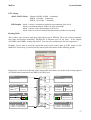
5.5 The EX8000 control panel
Each EX8000 connected to the MaXiO PCI host card has its own control panel windows that you
can access by double clicking on its name in the MaXiO Control Panel.
Clock Setting: Defines the system clock of the specific EX8000 unit.
Internal: Use the internal clock inside EX8000.
EDI: Use the clock from the MaXiO PCI host card (recommended default).
DIGITAL 1~4: Use the clock from the digital inputs of EX8000.
36
MaXiO
System Manual
ETC Setting
ADAT S/MUX Mode: - Normal (44 kHz ,48 kHz – 8 channels)
- SMUX 1 (96 kHz – 4 channels)
- SMUX 2 (192 kHz – 2 channels)
LED Display: - Mode 1 (shows a continuous graphical representation of the level)
- Mode 2 (continuous display with level meter peak hold)
- Mode 3 (shows a dot representation of the level)
- Mode 4 (the level meter will hold the maximum level that was reached)
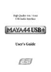
Routing Table:
This is where you can route input ports and output ports of EX8000. The 4 pair of stereo channels
look alike and function identically. EX8000 has 4 different types of I/O ports – E.D.I, Digital
(AES/EBU and S/PDIF), Analog and ADAT. You can select an input port for each output port.
Example: If you want to send the signal that comes from analog input to E.D.I output (to the
MaXiO PCI host card), you would set the control panel like shown on the following picture.
Please have a look at the following audio routing table that shows you all the audio routing options
of EX8000 when connected to the MaXiO PCI host card.
E.D.I
E.D.I IN
ANALOG
ADAT
8CH 24-bit/192kHz
E.D.I
DIGITAL IN
4 XLR In
4 RCA In
E.D.I OUT
DIGITAL
8CH 24-bit/192kHz
DIGITAL
~ Professional
{ Consumer
ANALOG
ADAT
DIGITAL OUT
E.D.I
{ Professional
~ Consumer
E.D.I
ANALOG IN
DIGITAL
8 XLR / TRS IN
ADC
MIC / LINE, GAIN
ADAT OPTICAL IN
~ Normal : 8CH 24-bit/48kHz
{ S/MUX 2 : 4CH 24-bit/96kHz
{ S/MUX 4 : 2CH 24-bit/192kHz
ANALOG
ADAT
ANALOG OUT
E.D.I
ANALOG
ADAT
DAC
E.D.I
DIGITAL
4 XLR Out
4 RCA Out
8 XLR balanced OUT
8 TRS balanced OUT
ADAT OPTICAL OUT
E.D.I
~ Normal : 8CH 24-bit/48kHz
{ S/MUX 2 : 4CH 24-bit/96kHz
{ S/MUX 4 : 2CH 24-bit/192kHz
37
MaXiO
System Manual
Digital Audio
Input Port Select: This is where you can switch between the coaxial S/PDIF digital input and
the XLR AES/EBU digital input for each of the 4 digital inputs available in
each format.
PLL status: Shows if an S/PDIF (or AES/EBU) connection is made. If Lock is displayed, an
S/PDIF (or AES/EBU) signal is detected at the specific input. If Unlock is
displayed, no signal is detected.
Format: - Professional (IEC 958 Type 1): EX8000 digital in/out format is AES/EBU.
- Consumer (IEC 958 Type II): EX8000 digital in/out format is S/PDIF.
Note that you can set this to Professional but keep the RCA (S/PDIF) port. This would
allow you to process an AES/EBU signal coming in on an unbalanced S/PDIF cable.
Analog Output Level Control: This is where you can control the analog output level for each
playback / output channel.
38
MaXiO
System Manual
6. Applications Setup
This chapter contains basic configuration examples for some popular software applications. Please
also refer to the manual of the audio software you use for detailed information.
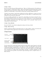
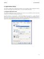
6.1 Windows Multimedia setup
The Windows Multimedia setup is required if you want to use your MaXiO system as the main
sound device for Windows multimedia applications.
Go to My computer-> Control panel -> Sounds and Audio Device Properties -> Audio. Select the
MaXiO driver as your playback device. You can choose MaXiO Multi Wave (as multichannel device
for consumer audio applications supporting multichannel playback like DVD player applications) or
MaXiO Stereo Wave(SPDIF/PCM) (as classical stereo playback device).
39
MaXiO
System Manual
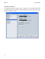
6.2 Cubase and Nuendo
After launching Cubase or Nuendo, go to Device -> Device Setup -> VST Multitrack. Select ASIO
2.0 –MaXiO as ASIO device. Then go to Default MIDI Ports and select MaXiO MIDI. Note:
clicking the ASIO Control Panel button will not do anything here. Make sure you click the Apply
button after changing the settings.
40
MaXiO
System Manual
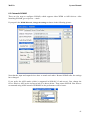
6.3 Cakewalk SONAR
There are few steps to configure SONAR, which supports either WDM or ASIO drivers. After
launching SONAR, go to Options > Audio.
If you prefer the WDM/KS mode, change the settings as shown in the following picture:
Note that the input and output drivers have to match each other. Restart SONAR after the settings
have changed.
If you prefer the ASIO mode (which is supported in SONAR 2.2 and newer), first, change the
Driver Mode to ASIO on the Advanced tab of as shown below. Then restart SONAR. Note that we
recommend using ASIO instead of WDM/KS as the performance will be better.
41
MaXiO
System Manual
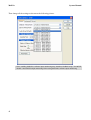
Then change all the settings as shown on the following picture:
·
42
Note: enabling SONAR’s software input monitoring may introduce feedback loops. You MUST
disable / mute MaXiO input monitoring before using SONAR’s software input monitoring.
MaXiO
System Manual
6.4 Wavelab
After launching Wavelab, go to Options -> Preference -> Audio Card. Select either MME-WDM
MaXiO Stereo Wave(SPDIF/PCM) or ASIO 2.0 –MaXiO.
MME configuration
ASIO configuration
43
MaXiO
System Manual
6.5 Tracktion
The MaXiO XD system comes bundled with the full version of Tracktion – a professional recording
and MIDI production software by Mackie / Raw Material Software. After launching Tracktion,
select Settings then go to the audio devices tab. Choose ASIO 2.0 - MaXiO as playback and record
device as shown below.
44
MaXiO
System Manual
7. DirectWIRE 3.0
7.1 What is DirectWIRE?
DirectWIRE is a 100% purely digital wire!
DirectWIRE is a driver technology, developed by ESI, which can be used for routing audio streams
internally within applications using EWDM Audio MIDI Drivers.
With the DirectWIRE router, an application can record from other application’s audio outputs
without external wiring or any loss of data when they are running at the same time.
DirectWIRE also allows you to easily rip any audio stream in real time by transferring data thru
DirectWIRE from MP3s, live On-line Broadcast and On-demand content, and more.
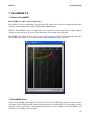
7.2 DirectWIRE Panel
Click on DirectWIRE on the MaXiO control panel. The DirectWIRE panel window as shown below
will appear. DirectWIRE digital virtual wiring technology, developed by ESI, routes audio streams
internally within applications using standard audio drivers such as WDM, ASIO and MME, even
when they are running at the same time.
45
MaXiO
System Manual
The number on the row represents the input or output port.
The columns represent ins and outs (on and off) of the respected drivers.
Patch the virtual cables from one point to another as you drag the mouse.
INPUT section is a new feature of DirectWIRE 3.0. It is used to route signals from MaXiO's
hardware inputs.
MME section represents general application's I/O:
Ex.) WinAmp, WaveLab (non ASIO mode), Cakewalk, Audition, Vegas, etc.
WDM section represents Multi-MME application’s I/O:
Ex.) SONAR (when using WDM/KS), PowerDVD, WinDVD, etc.
ASIO section represents ASIO application’s I/O:
Ex.) Cubase, Logic, Reason, Nuendo, SONAR (when using ASIO), Samplitude, etc.
GSIF section represents GSIF application like GigaStudio.
Note: some applications support multiple driver modes.
7.3 DirectWIRE examples
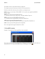
Example 1. Recording from WinAmp(MME) to WaveLab(MME):
Note: If you want to record what's played back in WinAmp, but don't want to hear the sound, you
should click the ‘OUT’ button in the MME section so it'll change to ‘OFF’ (
).
46
MaXiO
System Manual
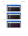
Example 2. Recording from WinAmp(MME) to SONAR(WDM):
Example 3. Recording from WinAmp(MME) to Cubase, Logic, Nuendo(ASIO):
Example 4. Recording from GigaStudio(GSIF) to SONAR(WDM):
47
MaXiO
System Manual
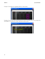
Example 5. Recording from GigaStudio(GSIF) to Cubase(ASIO):
Example 6. Let's say you want to quickly dub some vocal over an audio track. It's very simple with
DirectWIRE 3.0, you just have to make connections similar to these:
48
MaXiO
System Manual
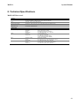
8. Technical Specifications
MaXiO PCI host card
y General
PCI Interface
Audio
System Clock Support
32bit, PCI Bus-Mastering support
PCI slot compatibility – designed to suit +3.3V and/or +5V PCI slot
Total 32-in / 32-out, 24bit, audio interface
Full Duplex - Simultaneous Record / Playback
Internal (44.1, 48.0, 88.2, 96.0, 176.4, 192.0 kHz), Word clock, Digital In, E.D.I
MIDI I/O
1-in / 1-out 16 MIDI channel , Standard MIDI 5-pin DIN
WORD Clock I/O
FS / 256*FS, BNC Connector
y Digital Audio
Coaxial (S/PDIF)
ADAT
E.D.I
M.D.I
Connector
Impedance
Format
Sample rate
Connector
Format
Sample rate
Connector / Cable
Format
Sample rate
Connector / Cable
Format
Sample rate
RCA (Coaxial) I/O
XLR : 110ohm, RCA : 75ohm
IEC-60958 Professional / Consumer
44.1, 48.0, 88.2, 96.0, 176.4, 192.0 kHz
TOS-Link (Optical) I/O
ADAT® protocol
44.1, 48.0kHz (8channel)
88.2, 96.0kHz (4channel - SMUX )
176.4, 192.0kHz (2channel - SMUX )
IEEE1394 compatible
E.D.I protocol ( 8-in / 8-out audio stream & control)
44.1, 48.0, 88.2, 96.0, 176.4, 192.0 kHz
SCSI compatible / Exclusive M.D.I Cable
4 X E.D.I (32-in / 32-out audio stream) & MIDI
44.1, 48.0, 88.2, 96.0, 176.4, 192.0 kHz
49
MaXiO
System Manual
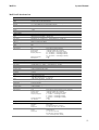
EX8000
y General
Type
19" rack mounted, digital audio interface
Audio
Total 8-in / 8-out, 24bit, audio interface
System Clock Support
Internal (44.1, 48.0, 88.2, 96.0, 176.4, 192.0 kHz), Word Clock, Digital In, E.D.I
WORD Clock IN
FS / 256*FS, BNC Connector
Power
AC IN 100V ~ 240V, 50Hz ~ 60Hz, 30W
Weight
3.5kg
Dimensions
482(mm) x 180(mm) x 86(mm)
y Analog Inputs
Type
Balanced 1/4” TRS (Balanced XLR ) Input
Level
+4dBu Nominal (@-16.2dBFS) , +20.2dBu max
Gain Range
0.0dB (@Gain min, +20.2dBu max) ~ +29.0dB (@Gain max, -7.8dBu max)
Frequency Response
20Hz to 20kHz, +/- 0.1dB
THD + N
0.0003% A-weighted (@ -3dBFS)
Dynamic Range
116dB A-weighted
CMRR
75dB
Impedance
10K ohm (1/4” TRS), Low impedance : 3K ohm (XLR)
A/D Converter
Type
Dynamic Range
S/(N+D) Ratio
Frequency Response
Interchannel Isolation
Gain Mismatch
24bit, 192KHz, 128X Oversampling
123dB (@ -60dBFS with A-Weighted)
110dB (@ -1dBFS, measurement method)
6.5 ~ 21.768KHz, +/- 0.001dB (@ fs=48KHz)
6.5 ~ 43.536KHz, +/- 0.003dB (@ fs=96KHz)
6.5 ~ 87.072KHz, +/- 0.007dB (@ fs=192KHz)
123dB
0.1dB
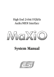
y Microphone Pre-amp
Type
Level
Gain Range
Equivalent Input Noise
THD + N
Dynamic Range
CMRR
Impedance
Balanced XLR (+48V Phantom Power support)
500 mV max (-3.8dBu)
+25.0dB (@Gain min, -3.8dBu) ~ +73dB (@Gain max, -51.8dBu)
- 135.5dBu (@ 0 ohm, 20Hz ~ 20kHz)
0.00065% A-weighted (@ gain+35dB)
103dB A-weighted (@ gain +35dB)
90dB
1.5K ohm
y Analog outputs
Type
Frequency Response
+4dBu Balanced XLR output
-10dBv Balanced/Unbalanced 1/4” TRS output
+4dBu Nominal (@-16dBFS) , +20.0dBu max
-10dBu Nominal (@-16dBFS) , +8.2dBu max
20Hz to 20kHz, +/- 0.05dB
Analog Filter
3-pole low-pass filter
Level
THD + N
0.0001% A-weighted (@ -3dBFS)
Dynamic Range
118dB A-weighted
Impedance
110 ohm (1/4” TRS), 110 ohm (XLR)
D/A Converter
Type
Dynamic Range
S/(N+D) Ratio
Frequency Response
Interchannel Isolation
Gain Mismatch
24bit, 192KHz, 128X Oversampling, 8 times digital filter
120dB (@ -60dBFS with A-Weighted)
100dB (@ -1dBFS, measurement method)
0 ~ 21.7KHz, +/- 0.002dB (@ fs=48KHz)
0 ~ 43.5KHz, +/- 0.002dB (@ fs=96KHz)
0 ~ 87.0KHz, +/- 0.002dB (@ fs=192KHz)
120dB
0.15dB
y Digital Audio
AES/EBU, Coaxial (S/PDIF)
ADAT
E.D.I
50
Connector
Impedance
Format
Sample rate
Connector
Format
Sample rate
Connector
Format
Sample rate
XLR (AES/EBU), RCA (S/PDIF) I/O
XLR : 110ohm, RCA : 75ohm
IEC-60958 Professional / Consumer
44.1, 48.0, 88.2, 96.0, 176.4, 192.0 kHz
TOS-Link (Optical) I/O
ADAT® protocol
44.1, 48.0kHz (8channel)
88.2, 96.0kHz (4channel - SMUX )
176.4, 192.0kHz (2channel - SMUX )
IEEE1394 compatible
E.D.I protocol
44.1, 48.0, 88.2, 96.0, 176.4, 192.0 kHz (8 channel)
MaXiO
System Manual
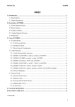
MaXiO 032 breakout box
y General
Type
Half rack type, M.D.I Based Digital audio interface
Audio
Total 32-in / 32-out, 24bit, audio interface
System Clock Support
Internal (44.1, 48.0, 88.2, 96.0, 176.4, 192.0 kHz), Word Clock, Digital In, E.D.I
MIDI I/O
1-in / 1-out 16 MIDI channel , Standard MIDI 5-pin DIN
WORD Clock I/O
FS / 256*FS, BNC Connector
Power
M.D.I Cable Power
Weight
1,035g
Dimensions
216(mm) x 160(mm) x 44(mm)
y Analog Inputs
Type
Balanced 1/4” TRS (Balanced XLR ) Input
Level
+4dBu Nominal (@-16.2dBFS) , +20.2dBu max
Gain Range
0.0dB (@Gain min, +20.2dBu max) ~ +29.0dB (@Gain max, -7.8dBu max)
Frequency Response
20Hz to 20kHz, +/- 0.1dB
THD + N
0.0003% A-weighted (@ -3dBFS)
Dynamic Range
116dB A-weighted
CMRR
75dB
Impedance
10K ohm (1/4” TRS), Low impedance : 3K ohm (XLR)
A/D Converter
Type
Dynamic Range
S/(N+D) Ratio
Frequency Response
Interchannel Isolation
Gain Mismatch
24bit, 192KHz, 128X Oversampling
123dB (@ -60dBFS with A-Weighted)
110dB (@ -1dBFS, measurement method)
6.5 ~ 21.768KHz, +/- 0.001dB (@ fs=48KHz)
6.5 ~ 43.536KHz, +/- 0.003dB (@ fs=96KHz)
6.5 ~ 87.072KHz, +/- 0.007dB (@ fs=192KHz)
123dB
0.1dB
y Microphone Pre-amp
Type
Level
Gain Range
Equivalent Input Noise
THD + N
Dynamic Range
CMRR
Impedance
Balanced XLR (+48V Phantom Power support)
500 mV max (-3.8dBu)
+25.0dB (@Gain min, -3.8dBu) ~ +73dB (@Gain max, -51.8dBu)
- 135.5dBu (@ 0 ohm, 20Hz ~ 20kHz)
0.00065% A-weighted (@ gain+35dB)
103dB A-weighted (@ gain +35dB)
90dB
1.5K ohm
y Analog outputs
Type
Frequency Response
+4dBu Balanced XLR output
-10dBv Balanced/Unbalanced 1/4” TRS output
+4dBu Nominal (@-16dBFS) , +20.0dBu max
-10dBu Nominal (@-16dBFS) , +8.2dBu max
20Hz to 20kHz, +/- 0.05dB
Analog Filter
3-pole low-pass filter
Level
THD + N
0.0001% A-weighted (@ -3dBFS)
Dynamic Range
118dB A-weighted
Impedance
110 ohm (1/4” TRS), 110 ohm (XLR)
D/A Converter
Type
Dynamic Range
S/(N+D) Ratio
Frequency Response
Interchannel Isolation
Gain Mismatch
24bit, 192KHz, 128X Oversampling, 8 times digital filter
120dB (@ -60dBFS with A-Weighted)
100dB (@ -1dBFS, measurement method)
0 ~ 21.7KHz, +/- 0.002dB (@ fs=48KHz)
0 ~ 43.5KHz, +/- 0.002dB (@ fs=96KHz)
0 ~ 87.0KHz, +/- 0.002dB (@ fs=192KHz)
120dB
0.15dB
y Digital Audio
Coaxial (S/PDIF)
ADAT
Connector
Impedance
Format
Sample rate
Connector
Format
Sample rate
RCA (S/PDIF) I/O
RCA : 75ohm
IEC-60958 Professional / Consumer
44.1, 48.0, 88.2, 96.0, 176.4, 192.0 kHz
TOS-Link (Optical) I/O
ADAT® protocol
44.1, 48.0kHz (8channel)
88.2, 96.0kHz (4channel - SMUX )
176.4, 192.0kHz (2channel - SMUX )
51
MaXiO
System Manual
END USER WARRANTY
Trademarks
ESI, MaXiO XD, MaXiO 032, MaXiO and EX8000 are trademarks of ESI. Windows is a trademark of Microsoft Corporation. Other
product and brand names are trademarks or registered trademarks of their respective companies.
End User Warranty
ESI warrants this product, under normal use, to be free of defects in materials and workmanship for a period of One(1) year from date of
purchase, so long as: the product is owned by the original purchaser, with proof of purchase from an authorized ESI dealer. This
warranty explicitly excludes power supplies and included cables which may become defective as a result of normal wear and tear.
In the event that ESI receives, from an original purchaser and within the warranty coverage period, written notice of defects in materials
or workmanship, ESI will either replace the product, repair the product, or refund the purchase at its option. To obtain warranty service,
the original purchaser or his authorized dealer must fill the support contact form at http://www.esi-pro.com. In the event repair is required,
shipment to and from ESI and possible handling charges shall be borne by the purchaser. ESI will not accept returns without prepaid
shipments. In the event that repair is required, a Return Authorization Number must be obtained from ESI. After this number is obtained,
the unit should be shipped back to ESI in a protective package with a description of the problem and the Return Authorization Numer
clearly written on the package. All such returns must be shipped to ESI headquarters in Seoul, Korea (or US Office).
In the event that ESI determines that the product requires repair because of user misuse or regular wear, it will assess a fair repair or
replacement fee. The customer will have the option to pay this fee and have the unit repaired and returned, or not pay this fee and have
the unit returned and un-repaired.
The remedy for breach of this warranty shall not include any other damages. ESI will not be liable for consequential, special, indirect, or
similar damages or claims including loss of profit or any other commercial damage, even if its agents have been advised of the
possibility of such damages, and in no event will ESI’s liability for any damages to the purchaser or any other person exceed the price
paid for the product., regardless of any form of the claim. ESI specifically disclaims all other warranties, expressed or implied.
Specifically, ESI makes no warranty that the product is fit for any particular purpose.
The FCC and CE Regulation Warning
This device complies with Part 15 of the FCC Rules. Operation is subject to the following two conditions: (1) this device may not cause
harmful interference, and (2) this device must accept any interference received, including interference that may cause undesired
operation. Caution: Any changes or modifications in construction of this device with are not expressly approved by the party responsible
for compliance, could void the user's authority to operate equipment.
NOTE: This equipment has been tested and found to comply with the limits for a Class A digital device, pursuant to Part 15 of the FCC
Rules. These limits are designed to provide reasonable protection against harmful interference when the equipment is operated in a
commercial environment. This equipment generates, uses, and can radiate radio frequency energy and, if not installed and used in
accordance with the instruction manual, may cause harmful interference to radio communications. Operation of this equipment in a
residential area is likely to cause harmful interference in which case the user will be required to correct the interference at his own
expense. If necessary, consult an experienced radio/television technician for additional suggestions.
Correspondence
For technical support inquiries, contact your nearest dealer, local ESI distributor or ESI directly at:
ESI
Suite 1206, Woolim e-Biz Center II,
16 Yangppyoung-dong 3-ga, Youngdungpo-gu,
Seoul, Korea, 150-834
www.esi-pro.com
Technical Support:
Online Support Community
North and South America (English)
UK (English)
Germany (German)
Sales:
International
USA
Germany
www.esiforum.com
[email protected]
[email protected]
[email protected]
[email protected]
[email protected]
[email protected]
All features and specifications subject to change without notice.
·
Parts of this manual are continually being updated. Please check our web site www.esipro.com occasionally for the most recent update information.
·
52