1
Bedienungsanleitung
Operating Instructions
Elektronisches Vorschaltgerät
Electronic Ballast
EB 575/800
- flicker free -
Arnold & Richter Cine Technik
Lighting Division
Pulvermühle
D-83071 Stephanskirchen
Tel. (0)8036-3009-0
Fax (0)8036-2471
L2.76184KH
LICHTTECHNIK
_______________________________________________ Deutsch ____
INHALT
Seite
1. Allgemeine Hinweise ..................................................................................... 3
2. Wichtige Sicherheitshinweise ........................................................................ 3
3. Produktbeschreibung ...................................................................................... 5
4. Inbetriebnahme des EVG ............................................................................... 6
4.1 Einschalten des EVG............................................................................. 6
4.2 Einstellung der Lichtintensität .............................................................. 6
4.3 Geräuschminderung .............................................................................. 6
4.4 DMX-Fernsteuerung ............................................................................. 7
4.5 Einstellung der Geräteadresse ............................................................... 7
5. Technische Daten ........................................................................................... 8
6. Störungssuche................................................................................................. 9
7. Anschlußbelegung ........................................................................................ 17
8. Anordnung der Bedienelemente ................................................................... 18
_______________________________________________ English _____
Contents
Page
1. General Remarks .......................................................................................... 10
2. Important Safety Instructions ....................................................................... 10
3. Product Description ...................................................................................... 12
4. Start-Up Procedure ....................................................................................... 13
4.1 Energizing System............................................................................... 13
4.2 Control of Light Intensity .................................................................... 13
4.3 Reduction of Lamp Noise ................................................................... 13
4.4 Remote Control DMX-512 ................................................................. 14
4.5 Selection of Device Address ............................................................... 14
5. Technical Data.............................................................................................. 15
6. Trouble Shooting Guide ............................................................................... 16
7. Connector Wiring ......................................................................................... 17
8. Operating Parts on Front Panel .................................................................... 18
02.10.13
-2-
LICHTTECHNIK
___________________________________________________________________________
Deutsch ____
BEDIENUNGSANLEITUNG
Elektronisches Vorschaltgerät EB 575/800
______________________________________________________________________________________________
1. Allgemeine Hinweise Vor der ersten Inbetriebnahme des Elektronischen Vorschaltgerätes EB 575/800 (EVG)
sind alle im Folgenden aufgeführten Informationen aufmerksam durchzulesen. Sie
enthalten wichtige Hinweise für die Sicherheit, den Gebrauch und die Wartung des
Gerätes. Die Gebrauchsanweisung ist sorgfältig aufzubewahren und an eventuelle
Nachbesitzer weiterzugeben.
______________________________________________________________________________________________
2. Wichtige
Sicherheitshinweise
2.1 Vorsicht Netzspannung! Lebensgefahr!
Vor dem Öffnen des EVG ist das Gerät vom Netz zu trennen (Netzstecker ziehen).
Nicht am Anschlußkabel, sondern am Stecker ziehen, um das Gerät vom Netz zu
trennen. Reparaturen sowie der Anschluß eines anderen Netzsteckers (siehe 2.2) dürfen
nur durch eingewiesenes Fachpersonal oder vom ARRI-Service durchgeführt werden.
2.2 Der Schutzkontaktstecker der Netzzuleitung ist nur für den Betrieb an 230V-Netzen
zulässig. Wird das Gerät an einem 120V-Netz betrieben, ist der Schutzkontaktstecker
durch einen für diese Netze zugelassenen Stecker zu ersetzen. Dieser Stecker muß für
den in diesem Fall auftretenden Strom ausreichend dimensioniert sein (siehe die
Angaben des Maximalstromes unter "5. Technischen Daten", Seite 8). Die jeweiligen
nationalen Vorschriften sind zu beachten.
Die Adern der Netzzuleitung sind durch folgenden Farbcode gekennzeichnet:
Schutzleiter / PE: grün/gelb
Neutralleiter:
blau
Phasenleiter:
braun
Vor dem Anschließen des Vorschaltgerätes an das Netz sind die Netzsteckdosen auf die
Einhaltung der Schutzmaßnahmen zu prüfen. Bei spannungsführendem Schutzleiter
darf die Steckdose unter keinen Umständen benutzt werden. Bei fehlendem Schutzleiter
ist entweder auf eine ordnungsgemäße Steckdose auszuweichen, ein Trenntrafo zu
benutzen, ein FI-Schutzschalter oder ein Anschlußkasten mit FI-Schutzschalter (30mA,
Erdanschluß und Meßeinrichtung) zu verwenden.
Hinweis: Zur Verhinderung von unbeabsichtigten Auslösungen durch Ableitströme und
vorübergehende Störungen muß darauf geachtet werden, daß die Summe der
Ableitströme der Betriebsmittel auf der Lastseite einer RCD (FI-Schutzschalter)
weniger als 1/3 des Bemessungsauslösestromes beträgt.
Der typische Ableitstrom dieses Gerätes beträgt 2,0 mA (gemäß EN 60598-1:1996,
Anhang G).
2.3 Für den Lampenwechsel einer an das Vorschaltgerät angeschlossenen Leuchte ist
das Vorschaltgerät auszuschalten und die Leuchte elektrisch vom Vorschaltgerät zu
trennen (Leuchtensteckverbinder).
2.4 Vor dem Lösen bzw. Anschließen des Lampenkabels an der Lampensteckverbindung ist das Gerät mit dem ON/OFF-Schalter auszuschalten. Es dürfen nur
original ARRI Lampenkabel mit für die Lampenleistung zugelassenem Querschnitt zum
Anschluß der Leuchte an das Vorschaltgerät verwendet werden. Der Betrieb von
Leuchten anderer Hersteller als ARRI am Vorschaltgerät ist nicht zulässig.
2.5 Das Elektronische Vorschaltgerät EB 575/800 entspricht den anerkannten Regeln
der Technik und den einschlägigen Sicherheitsbestimmungen DIN EN 60598/1 und
DIN EN 60950 für Elektrogeräte.
-3-
LICHTTECHNIK
___________________________________________________________________________
Deutsch ____
2.6 Das Gerät ist in ein Gehäuse der Schutzart IP 22 (tropfwassergeschützt) eingebaut.
Die in den technischen Daten (siehe Seite 8) und auf dem Typenschild angegebenen
Grenzwerte für die Netzspannung müssen unbedingt eingehalten werden.
Die zulässige Umgebungstemperatur liegt im Bereich -20°C bis +50°C. Beide
Seitenwände des Gehäuses sind als Außenkühler ausgeführt. Diese Außenkühler dürfen
nicht abgedeckt werden und die Lüftungsschlitze auf der Gehäuserückseite müssen frei
sein.
Das Vorschaltgerät darf nur auf festem, ebenem, trockenem und nicht heißem
Untergrund (Temperatur ≤ 50°C) aufgestellt werden. Bei Rutschgefahr Gerät zusätzlich
gegen Verrutschen sichern.
Weiterhin muß das Gerät gegen direkte Sonneneinstrahlung geschützt werden. Ein
Regenschutz ist erforderlich, wenn die Beanspruchung des Vorschaltgerätes durch
Sprühwasser über dem durch IP 22 vorgegebenen Rahmen liegt.
Das EVG darf nicht im betauten Zustand und nicht in aggressiven oder explosiven
Medien eingeschaltet werden.
2.7 Das Vorschaltgerät darf nur gemäß den in der Bedienungsanleitung beschriebenen
Betriebsbedingungen eingesetzt werden. Der Hersteller haftet nicht für evtl. Schäden,
die durch nicht bestimmungsgemäßen Gebrauch oder falsche Bedienung verursacht
werden.
2.8 Der Benutzer dieses Gerätes wird dringend aufgefordert, die nachfolgenden
Hinweise zu beachten:
Verpackungsmaterial ordnungsgemäß entsorgen.
Ein Gerät, das Schaden aufweist, nicht in Betrieb nehmen.
Zur Gewährleistung eines sicheren Betriebes Gerät nur nach den Vorgaben in der
Bedienungsanleitung einsetzen und gemäß Typenschildangaben anschließen und
betreiben.
Im Fehlerfall Gerät vom Netz trennen (Netzstecker ziehen). Nicht am
Anschlußkabel, sondern am Stecker ziehen, um das Gerät vom Netz zu trennen.
Reparaturen, Ersatzteilaustausch und Eingriffe in das Gerät nur von einer für diese
EVG geschulten Fachkraft oder vom ARRI-Service ausführen lassen.
Für Reparaturen dürfen nur original Ersatzteile verwendet werden!
Ausgediente Geräte sofort unbrauchbar machen, dazu Netzstecker ziehen und
anschließend Anschlußleitung am EVG durchtrennen. Danach das Gerät einer
ordnungsgemäßen Entsorgung zuführen.
Kindern die Benutzung von EVG untersagen.
Gerät nur trocken oder mit feuchtem Tuch reinigen. Vorher Netzstecker ziehen.
EVG niemals in Wasser tauchen.
Anschlußkabel oder Leuchtenkabel nicht zum Tragen benutzen, nicht über scharfe
Kanten ziehen, nicht unter Türen quetschen oder anderweitig einklemmen.
Gerät ausschalten, wenn es nicht benötigt wird. Gerät nur unter den in der
Bedienungsanleitung vorgegebenen Umgebungsbedingungen betreiben.
-4-
LICHTTECHNIK
___________________________________________________________________________
Deutsch ____
3. Produktbeschreibung Das Elektronische Vorschaltgerät EB 575/800 von ARRI bildet eine Funktionseinheit
mit den für das EVG zugelassenen Tageslichtscheinwerfern (siehe Abb. 1.a + 1.b, Seite
17). Es ist für die professionelle Anwendung sowohl in Gebäuden als auch für den
Betrieb im Freien geeignet (Schutzart IP22, Schutz gegen Tropfwasser).
Hinweis: Das elektronische Vorschaltgerät EB 575/800 entspricht den geltenden EMVVorschriften.
Es erfüllt in weiten Bereichen die Grenzwerte der Klasse B, ist aber grundsätzlich unter
Klasse A, Gruppe 1 einzustufen.
Anmerkung: Obwohl die Grenzwerte der Klasse A für industrielle und kommerzielle
Betriebsräume abgeleitet werden, dürfen die Verwaltungen das Errichten und den
Betrieb von Geräten der Klasse A - mit allen dazugehörigen Maßnahmen - auch im
Wohnbereich oder in solchen Betrieben erlauben, die direkt an ein öffentliches
Niederspannungsnetz angeschlossen sind (DIN EN 55011).
Das Gerät erfüllt die Anforderungen der EN 61000-3-2.
Beim Einsatz von Elektronischen Vorschaltgeräten (EVG) für Metalldampflampen
ergeben sich eine Reihe von Vorteilen gegenüber den bisherigen
Drosselvorschaltgeräten (DVG):
Flickerfreies Licht
Keine Kamerasynchronisation erforderlich
Typischer Lichteinbruch 3%
Lichtausbeute um ca. 5% erhöht
Konstante Brennerleistung
Gleichbleibende Farbtemperatur
Stabile, optimale Farbqualität des Lichtes
Einstellung der elektrischen Leistung zwischen 50 und 100%
Netzspannungsschwankungen im zugelassenen Spannungsbereich (siehe Technische
Daten auf Seite 8) haben keinen Einfluß auf die Lichtstabilität
Änderungen der Netzfrequenz bis max. 10% bleiben ebenso ohne Einfluß auf das
Licht
Brennerlebensdauer um 20% höher
Geringeres Volumen und Gewicht gegenüber DVG
CCL (Compensation of Cable Losses)
Bewirkt die Kompensation der in den Leuchtenkabeln auftretenden elektrischen
Verluste durch automatische Erhöhung der Ausgangsleistung (nur in Verbindung
mit geeigneten 800 W Scheinwerfern).
-5-
LICHTTECHNIK
___________________________________________________________________________
4. Inbetriebnahme
des EVG
Sämtliche Bedienelemente und Kabelverbindungen
angeordnet (siehe Abb. 2, Seite 18).
sind
Deutsch ____
auf
der
Frontplatte
4.1 Einschaltvorgang
Prüfen, ob sich der "Lamp" Schalter in der "O"-Stellung befindet
Geprüfte Leuchte über Verbindungskabel an das EVG anschließen.
Die Gesamtlänge der Verbindungskabel darf maximal 100 Meter betragen.
EVG ans Netz anschließen
Prüfen, ob der Netzautomat ("Mains") eingeschaltet ist
Schutzleiteranschluß überprüfen. Bei korrektem Schutzleiteranschluß leuchtet die
grüne LED "PE" auf der Frontplatte. Bei nicht korrektem Schutzleiteranschluß EVG
sofort vom Netz trennen (Netzstecker ziehen)!
Die Nennleistung der angeschlossenen Leuchte (575 W oder 800 W) wird vom
EVG automatisch erkannt.
Rechts neben dem Lampensteckverbinder zeigen zwei LEDs die aktuelle erkannte
Leuchte an.
"Lamp" Schalter sowohl am EVG als auch am Scheinwerfer einschalten.
Die Lampe startet nach ca. 3 Sekunden.
Die "DMX" LED leuchtet, wenn das Gerät über die Fernsteuerung eingeschaltet
wurde. In diesem Fall lässt sich das EVG nicht mit dem "Lamp" Schalter
ausschalten
Bei erfolgreicher Zündung leuchtet die gelbe LED "LAMP" auf der Frontplatte.
4.2 Einstellung der Lichtintensität
Die Lichtintensität der warmgelaufenen Lampe kann durch Drehen des DimmPotentiometers verändert werden. Dabei wird die elektrische Lampenleistung zwischen
50% und 100% des Nennwertes eingestellt (linker Poti-Anschlag min., rechter Anschlag
max. Leistung).
Wenn das Gerät über eine Fernbedienung bedient wird ("DMX" LED leuchtet) ist das
Dimm-Potentiometer auf der Frontplatte außer Funktion!
4.3 Geräuschminderung
Beim flackerfreien Betrieb der Leuchten können in der Leuchte unerwünschte
Geräusche entstehen, die auf die besondere Betriebsweise zurückzuführen sind. Der
"Low Noise" Taster ermöglicht die Wahl verschiedene Betriebsweisen des EVG:
1. In den „low noise“ Einstellungen "LN 50 Hz" bzw. "LN 60 Hz" (rote LED
Anzeigen) wird das Geräusch in der Leuchte stark reduziert.
Das Licht ist jetzt nicht mehr flackerfrei!
In dieser Betriebsweise gilt die gleiche Einschränkung für die Filmgeschwindigkeit
wie sie auch beim Drosselbetrieb mit 50 Hz (24/25 fps) bzw. 60 Hz (30 fps)
Netzfrequenz Gültigkeit hat.
Alle anderen Vorteile der Elektronischen Vorschaltgeräte bleiben jedoch erhalten.
2. In der „Flicker Free“ Einstellung "FF 75 Hz" (grüne LED Anzeige) arbeitet das EVG
im flackerfreien Modus. Die Metalldampflampe strahlt gleichförmiges Licht aus.
3. In der „Flicker Free“ Einstellung "FF 1000 Hz" (weiße LED Anzeige) arbeitet das
EVG im flackerfreien Modus. Die Metalldampflampe strahlt gleichförmiges Licht
aus.
Diese Betriebsart ist dafür optimiert, bei der Benutzung von digitalen Kameras mit
hohen Bildraten hochauflösende Bilder zu erzielen.
Hinweis:
Mit dem Hand-Messgerät P.R.O.F. kann im Zweifelsfall die Flackerfreiheit
bzw. Frequenz des Lichtes direkt innerhalb weniger Sekunden überprüft
werden.
-6-
LICHTTECHNIK
___________________________________________________________________________
Deutsch ____
4.4 DMX-Fernsteuerung
Das Vorschaltgerät EB 575/800 kann über eine Fernsteuerung nach DMX 512 Standard
bedient werden. Die Anschlüsse hierfür befinden sich an der Rückseite des Gerätes.
Um das Gerät über die Fernsteuerung zu bedienen muss der Ein-/Ausschalter an der
Frontplatte des Gerätes ausgeschaltet sein! Wird das Gerät per Fernsteuerung bedient, so
leuchtet die "DMX" LED und das Dimm-Potentiometer auf der Frontplatte ist
deaktiviert.
Die Fernsteuerung des Gerätes erfolgt über zwei DMX-Kanäle. Ein Kanal dient der
Dimmung, der zweite, auf der nächsthöheren Adresse gelegene, schaltet das Gerät ein
bzw. aus. Die LED-Anzeige an der Rückseite des Gerätes zeigt die Adresse des
eingestellten Dimmkanales an!
Über den Dimmkanal kann durch Senden von Werten im Bereich 127 bis 255 die
Lampenleistung linear zwischen 50% und 100% der Nennleistung eingestellt werden.
Werte kleiner als 127 werden vom EVG als 127 (50%) interpretiert. Über den
Schaltkanal wird das Gerät durch Senden von 0 .. 127 ausgeschaltet, eingeschaltet wird
es durch Senden von 128 .. 255.
Achtung: Das Potential der Fernsteuersignale an den Buchsen 'DMX IN' und 'DMX
OUT' darf nicht mehr als 70 Volt (Spitzenspannung) gegenüber Schutzleiter annehmen.
4.5 Einstellung der Geräteadresse
Auf der Rückseite des Gerätes (siehe Abb. 3, Seite 18) zeigt eine LED-Anzeige die
DMX-Adresse des Dimmkanales des Gerätes an. Mit den Tasten "↑ " (aufwärts) und
"↓ " (abwärts) kann die angezeigte Adresse verändert werden. Innerhalb von zwei
Sekunden kann die neu eingestellte Adresse durch Drücken der Taste "ENTER"
übernommen und gespeichert werden.
Die grüne LED "Signal" zeigt an, dass auf der eingestellten DMX-Adresse (und der
darauffolgenden Schaltadresse) Signale gesendet werden.
-7-
LICHTTECHNIK
___________________________________________________________________________
5. Technische Daten
Deutsch ____
Netzanschluß
Eingangsleistung
Netzspannung
Netzstrom
Leistungsfaktor
:
:
:
:
1160 VA (max. im CCL-Modus)
90 - 130 V~ / 180 - 250 V~ 50/60 Hz 1, N, PE
11.1 – 8.9 A / 5,8– 4,4 A
cos ϕ ≈ 0,98
Lampenanschluß
Lampenleistung
Leistungsanpassung
:
:
Stromverlauf
:
Dimmung
Zündung
Lichtrippel
:
:
:
575 W / 800 W konstant geregelt
autom. Erkennung der Leuchtentypen
575 W und 800 W
Rechteck, 75 bzw. 1000 Hz im "FF" (Flicker Free) Modus;
Abgerundete Rechteckform, 50 Hz bzw. 60 Hz im "LN"
(low noise) Modus
Bereich 50 bis 100% des Nennwertes der Lampenleistung
Heiß- und Kaltstart
typ. < 3%
Abmessungen
B· H· T
Gewicht
Schutzart
:
:
:
202 · 141 · 335 mm
ca. 6,5 kg
IP 22
:
:
Dimmung; Adresse einstellbar (001 ... 511)
Gerät Ein/Aus; auf der nach Kanal 1 folgenden Adresse
:
:
:
:
:
Ground
DMX DMX +
frei
frei
Fernsteuerung
DMX-512 Standard
Kanal 1
Kanal 2
Pinbelegung:
PIN 1
PIN 2
PIN 3
PIN 4
PIN 5
-8-
LICHTTECHNIK
___________________________________________________________________________
6. Störungssuche
Deutsch ____
6.1 Wird das EVG mit der richtigen Netzspannung versorgt? Der zulässige Bereich ist
auf dem Typenschild vermerkt. EVG für mehrere Netzspannungsbereiche schalten
automatisch um.
6.2 Ist das EVG mit der richtigen Leistungsklasse an den Scheinwerfer angeschlossen?
6.3. EVG ans Netz anschließen und den Schutzleiteranschluß am Vorschaltgerät prüfen
(grüne LED "PE" muß leuchten).
6.4. Scheinwerfer an das ausgeschaltete EVG anschließen. Dann ON/OFF-Schalter
einschalten. WARTEN. Nach ungefähr 5 Sekunden sollte die Lampe starten.
6.5. Wenn die Lampe nicht zündet, ist möglicherweise die Sicherheitsschleife durch den
Scheinwerfer unterbrochen - es ist zu prüfen, ob die Leuchtentür richtig geschlossen
und die Fresnellinse korrekt positioniert ist.
6.6 Ist das EVG an einer stabilen und ausreichend bemessenen Netzversorgung
angeschlossen?
6.7 Ist der Sicherungsautomat am EVG eingeschaltet?
6.8 Wenn die Kombination Vorschaltgerät/Verlängerungskabel/Leuchte nicht startet,
kann der Fehler in jeder der drei Einheiten vorliegen. Eine verdächtige Leuchte sollte
nicht mit einem anderen EVG erneut gestartet werden - andernfalls könnten zwei
zerstörte EVG das Ergebnis sein. Um zu Prüfen, ob ein EVG funktionstüchtig ist, ist
eine geprüfte Leuchte direkt ohne Verlängerungskabel an das EVG zu schalten.
6.9 Wenn das EVG nach einigen Minuten abschaltet, können verschiedene Ursachen
vorliegen.
Die Lampe selbst kann fehlerhaft sein oder das Ende ihrer Lebensdauer erreicht
haben.
Die Thermoschalter im EVG könnten aktiviert sein (rote LED-Anzeige "TEMP"),
weil die Umgebungstemperatur zu hoch ist oder das EVG direkter
Sonnenbestrahlung in heißer Umgebung ausgesetzt wurde. Auch könnte der freie
Zu- und Ablauf der Kühlluft im EVG verhindert sein. In diesen Fällen kann das
EVG nach Abkühlung und Beseitigung der Ursache für die Überhitzung wieder
gestartet werden.
Darüber hinaus kann sich das EVG, zum Schutz vor Zerstörung, abschalten, wenn
die Netzspannung zu hoch, zu niedrig oder mit Spannungsspitzen überlagert ist.
Beim Generatorbetrieb sollte die Generatorspannung zwischen 95 V und 125 V
bzw. 185 V und 245 V geregelt sein. Schaltet das EVG durch einen kurzzeitigen
Netzausfall ab, genügt das Aus- und Wiedereinschalten des EVG, um die Lampe
erneut zu starten.
Defekte in der Leuchte wie z.B. ein Erdschluß können ebenso zur Abschaltung
führen. In diesem Fall ist das EVG mit einer geprüften Leuchte zu testen. Wenn ein
Verlängerungskabel defekt erscheint, ist es unbedingt durch ein geprüftes Kabel
auszutauschen.
Wenn ein EVG ausgefallen ist, sollte es idealerweise zusammen
Verlängerungskabel und Leuchte vom ARRI-Service geprüft werden.
-9-
mit
LICHTTECHNIK
_______________________________________________
English _____
OPERATING INSTRUCTIONS
Electronic Ballast ARRI EB 575/800
______________________________________________________________________________________________
1. General Remarks
Please read the following operating instructions very carefully before using the
Electronic Ballast (EB) the first time. They contain important information and
instructions for the safety, use and maintenance of the appliance. For your own safety
please follow all safety instructions and warnings.
Keep the operating instructions carefully in a safe place and pass them to any future
owner.
______________________________________________________________________________________________
2. Important Safety
Instructions
2.1 Warning - High voltages inside ballast! Danger to life!
Disconnect EB from power supply before opening (pull out the line plug). Do not pull
on the connection cable, but on the plug, to disconnect the EB from mains. Any repairs
or changing of the line plug must only be carried out by qualified personnel or ARRIservice departments.
2.2 The standard European line plug is only permissible for use on 220 ... 250 V
supplies. For 100 ... 120 V supplies line plug has to be changed to a plug with protective
earth which is suitable for the higher current (see max. current in "Technical Data", page
15). When making connections be sure that the earth conductor is made longer than the
live or neutral conductors. This means that if the cable is strained the earth conductor
will be the last to be disconnected and so you will not be electrocuted. National
standards must be observed.
The cores in the main cable are colored in accordance with following code:
Protective earth: green/yellow
Neutral
blue
Live (Phase)
brown
Before connecting the Electronic Ballast ensure that the power supply is correctly wired.
Do not use without adequate earth connection unless either an isolation transformer or
an earth-leakage trip is employed.
Note: In order to avoid unwanted tripping due to leaking currents and transient
disturbances, care shall be taken that the collective leakage current of equipment on the
load side of a residual current device is less than 1/3 of its rated residual current.
The typical leakage current of this device is 2.0 mA (according EN 60598-1:1996,
appendix G).
2.3 Lamphead must be disconnected from Electronic Ballast or Electronic Ballast must
be disconnected from mains before fitting or replacing a lamp.
2.4 The Electronic Ballast must be switched off before connecting or disconnecting
either head or supply cable. Do not use other than original ARRI cables and connector
with permitted cross section of the leads. The ballast is only suitable for original ARRI
luminaires. Using other than original ARRI cables or luminaires may cause injury to the
user as well and/or damage to the ballast.
2.5 The Electronic Ballast satisfies the standards of the recognized state of the
engineering and the pertinent safety regulation of DIN EN 60598-1 and DIN EN 60950
for electrical appliances.
- 10 -
LICHTTECHNIK
_______________________________________________
English _____
2.6 Supply voltage must not exceed the ranges that are given in the "Technical Data"
(see page 15). Check that the power supply voltage and wiring are suitable for the
ballast to be used. Supply voltages which are greater or less than that specified for the
ballast can cause injury to the user as well as damage to the ballast.
The electronic of the EB is built in housing with protective class I and protective rate IP
22.
Ambient operating temperatures must be between -20°C and + 50°C!
Neither heat sinks nor air slots for ventilation should ever be covered or obstructed.
The EB must be placed only on solid, flat and dry ground. Temperature of the ground
should be less than 50°C. If the EB could slip over the ground, it must be fastened.
Protect EB against direct sunshine. Protection against rain is needed when wind pushes
water drops direct into the air slots of the EB (acc. to protective rate IP 22).
Do not operate the EB in high humidity (dew) or in aggressive or explosive gas-air
mixtures.
2.7 The Electronic Ballast must be used only according to the directions in this
"Operating Instruction". The manufacturer shall not be liable for any damages caused by
unintended use or wrong operation.
2.8 The user of the Electronic Ballast is urgently requested to observe the
following instructions:
Dispose of packing material properly.
Do not place the ballast into operation if damages are apparent.
To assure safe operation, use EB only according to the information given in these
operating instructions, connect and operate it as shown on the serial number plate.
In case of malfunction, disconnect the EB from mains (pull out the line plug).
Repairs, exchange of replacement parts and manipulations on the EB must be carried
out by a qualified personnel or ARRI service only.
Use only original spare parts for repairs.
Use only original accessories.
Make worn-out Electronic Ballasts inoperable immediately by pulling out the line
plug and cutting the line cable at the ballast. Then dispose of the Electronic Ballast
properly.
Make sure that children do not operate the EB.
Always switch off the EB and pull out line plug before you clean it or do
maintenance work on it.
Clean EB dry only or with a moist cloth. Never immerse it into water.
Do not use the connection cables of the EB for carrying, do not pull them over sharp
edges, clamp them under doors or clamp them in any other way.
Switch off EB when it is not needed.
- 11 -
LICHTTECHNIK
_______________________________________________
English _____
3. Product Description
The ARRI EB 575/800 is part of an optimized lighting system along with ARRI 575 W
or 800 W luminaires.
It is suitable for both professional indoor and outdoor use (IP22 protection).
Note: The Electronic Ballast EB 575/800 meets the European Council Directive
89/336/EEC of electromagnetic compatibility. Over an extensive range limits of radio
disturbance characteristic B are fulfilled. But on principle it has to be classified under
characteristic A, group 1.
Although limits of radio disturbance characteristic A are prescribed for industrial areas
administrative authority can allow the use of equipment with characteristic A in other
than industrial areas (DIN EN 55011).
The ballast meets the requirements of European Standard EN 61000-3-2.
Compared to magnetic ballasts there are a number of advantages when operating
daylight-lamps with ARRI Electronic Ballasts:
Flicker free light
No synchronization of cameras necessary
Typical lightripple max. 3 %
Light intensity increased by at least 5 %
Constant lamp power
Constant color temperature
Constant light quality
Control of electric power of the lamp between 50...100%
Variation in power supply voltage of 10% has no influence on the power of the lamp
(see also "Technical Data" for limits, on page 15).
Variation in power supply frequency of 10% has no influence on the power of the
lamp
Operating life time of the lamp increased by at least 20%
Substantially less volume and weight compared to magnetic ballasts
The ballast is built-in to a casing with type of protection IP22.
CCL (Compensation of Cable Losses)
The CCL function compensates the electrical losses on head to ballast cables by
automatically increasing the output power (only in conjunction with suitable 800 W
luminaires).
- 12 -
LICHTTECHNIK
_______________________________________________
English _____
4. Start-up procedure
All operating controls and cable connections are arranged on the front panel
(see fig. 2, page 18).
4.1 Energizing System
Check "Lamp" Switch to be in "O" position.
Connect the properly checked daylight luminaire with head to ballast cable to the
electronic ballast. The total length of head to ballast cables must not exceed 100 m.
Connect the electronic ballast to the power supply source.
Ensure main circuit breaker is in "ON" position
Check earth protection. If correct, the green LED "PE" on Front plate illuminates. If
not, disconnect EB from mains (pull out line plug) and check power supply and
socket (Ref. 2.2 on page 10)
The nominal power of the connected lamphead is detected automatically.
On the right side of the lamp connector two LEDs indicate the detected power of the
lamphead.
Set "Lamp" Switch to "I"-position as well on the EB as on the head.
Lamp will ignite after about 3 sec.
If the "DMX" LED is lit, the ballast is switched on by remote control. In this case the
ballast cannot be switched off by use of the "Lamp" switch.
The yellow LED "LAMP" on front plate is lit after successful ignition.
4.2 Control of light intensity
After warming up, the light intensity of the metal halide daylight-lamp may be controlled
by the dimming potentiometer (stepless). The nominal lamp power can be adjusted
between 50 - 100% (left stop = MIN, right stop = MAX of power).
If the ballast is controlled by remote control ("DMX" LED is lit) the dimming
potentiometer at the front plate is disabled.
4.3 Reduction of lamp noise
When metal halide daylight lamps are operated in the flicker free mode some noise
might occur, due to the special square-wave operation of the lamp.
1. In the “low noise” settings "LN 50 Hz" resp. "LN 60 Hz" (red LED indicating lights)
the noise will be substantially reduced, the amount depending on the lamp, in some
cases even to almost zero.
The light, however, is NOT flicker free any more.
When operating in this mode, the same limitations for speed of camera and/or shutter
angle apply as for magnetic ballasts operating at 50 Hz (24/25 fps) bzw. 60 Hz (30
fps). All other advantages of the electronic ballast will apply as before!
2. In the “Flicker Free” position "FF 75 Hz" (green LED indicating light) the electronic
ballast will operate flicker free, the lamp gives out a constant light.
3. In the “Flicker Free” position "FF 1000 Hz" (white LED indicating light) the
electronic ballast will operate flicker free, the lamp gives out a constant light. This
mode is specially designated to achieve high resolution pictures when using digital
cameras with high frame rates.
If in doubt (i.e. remote from ballast) with the flicker analyzer P.R.O.F light can be
checked to be flicker free or not.
- 13 -
LICHTTECHNIK
_______________________________________________
English _____
4.4 Remote Control DMX-512
Switching the ballast on/off and dimming of lamp power can be controlled by a remote
control according DMX-512 standard. Connectors and operating parts are placed at the
rear side of the ballast.
To operate the ballast by remote control, the ballast’s on/off switch must be in off
position! In case of remote operation, the "RC" LED is lit and the dimming
potentiometer on the front plate of the ballast has no function!
One channel is used for dimming the ballast, the second channel is used for switching
the ballast on and off. The address of the dimming channel is indicated by the LED
display at the rear panel of the ballast. The address for the on/off channel will be the
dimming address incremented by one. To switch the ballast 'on' a value between 128 and
255 must be send to this address. A value of 0 .. 127 will cause the ballast switching off.
Dimming is done by sending a value between 127 and 255 to the dimming address
which will correspond to lamp power regulated between 50% (127) to 100% (255) of
the nominal value.
Attention:
The potential of the remote control signals at the connectors may not
exceed 70 Volts (peak) against protective earth.
4.5 Selection of Device Address
At the upper part of the rear panel is a LED Display which indicates the current address
of the ballasts dimming channel. The "↑" (up) and "↓" (down) keys can be used to
change the displayed address. To take over the new address, the "ENTER" key has to be
pressed within two seconds.
The green LED "Signal" indicates that DMX signals are received at the adjusted channel
(dimming) and at the next channel (switching).
- 14 -
LICHTTECHNIK
_______________________________________________
English _____
5. Technical Data
Mains supply
Line Power
Supply Voltage
Nominal Current
Power Factor
:
:
:
:
Lamp connection
Lamp Power
:
Power Regulation
:
Current Characteristic :
1160 VA (max. in CCL mode)
90 - 130V~ / 180 - 250V~ 50/60 Hz 1, N, PE
11,1 – 8,9 A / 5,8 - 4,4 A
cos ϕ ≈ 0,98
Dimming
Starting
typical light ripple
:
:
:
575 / 800 W constant control
autom. recognition of lampheads 575 W and 800 W
square wave,
75 Hz or 1000 Hz in "FF" (Flicker Free) mode.
nearly square wave,
50 Hz or 60 Hz in "LN" (Low Noise) mode.
Range 50 - 100% of nominal lamp power
cold start and hot restrike
typ. < 3%
Dimensions
width · height · depth
Weight
Protective Rate
:
:
:
202 · 141 · 335 mm
ca. 6,5 kg
IP 22
Remote Control
According DMX-512
Channel 1
:
Channel 2
:
Dimming, Address selectable.
LED-Display shows current Address
Device on/off; Dimming address incremented by one.
Connector Wiring:
PIN 1
PIN 2
PIN 3
PIN 4
PIN 5
:
:
:
:
:
Ground
DMX DMX +
n.c.
n.c.
- 15 -
LICHTTECHNIK
_______________________________________________
English _____
6. Trouble Shooting
Guide
6.1 Does supply voltage correspond with ballast required voltage? Dual voltage
ballasts are autoswitching.
6.2. Ensure ballast wattage matches lamp power!
6.3 Ensure correct lamp is fitted!
6.4 Connect ballast to power supply and test earth (green LED "PE" has to be lit).
6.5 Re-energizing system:
Ensure ON/OFF Switch is in "OFF" position.
Switch ON/OFF switch to "ON". Switch should now illuminate. - WAITAfter approx. 5 seconds lamp should ignite.
6.6 If lamp does not strike, the safety circuit may be broken - check if lens door is fully
shut and the lens safety switch is activated.
6.7 Is there a good power supply to the ballast?
6.8 Is the ballast main circuit breaker in ON position?
6.9 If a ballast / head to ballast cable / luminaire does not work then all three units
should be considered faulty.
Do not try a suspected luminaire with another ballast - you may end up with two faulty
ballasts!
To check if a ballast is good, run it with a known good luminaire and known good head
to ballast cable.
6.10 If a ballast cuts out after running a few minutes there are a number of possible
failures:
The lamp itself may be faulty or at the end of its life.
The thermal cut-out in the ballast may have activated (Red LED "TEMP" on front
plate is lit) due to extreme ambient temperature or exposure to direct sunlight in hot
summer conditions .
The ventilation might be restricted. In such a case the ballast can be used after it had
cooled down and the condition causing the overheating is removed.
If the power supply exceeds the limits or has spikes or drop-outs the ballast switches
off to protect itself. If running on a generator the output should be regulated between
95 - 125V / 185 - 245V.
If a ballast has cut off due to a momentary supply drop-out switch the ballast "OFF"
and "ON" again. The ballast should start up as normal.
Earth leakage of luminaires or head to ballast cables will also cause the protection
circuit to be activated. Test the ballast with a known good luminaire. If cables are
suspect, they should be exchanged with known good cables.
If a ballast is found to be faulty ideally it should be returned together with the luminaire
and head to ballast cable to the ARRI-service location for examination.
- 16 -
LICHTTECHNIK
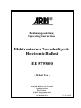
Spannungsversorgung Elektronisches Vorschaltgerät
Electronic Ballast
Power Supply
(575 W)
Ausgangsbelegung /
Output wiring, lamp
Funktion /
Function
Lampe/
Lamp
ARRI Daylight 575, Compact 575
ARRISUN 5, ARRI X5, ARRI D5
Steckerbelegung /
Connector wiring,
socket
EB 575/800
VEAM Schaltbau
1
90-130V~
180-250V~
50/60Hz
N
Rechteckwandler /
Square Wave
Converter
Zündzeitbegrenzer
0.75s
IgnitionTime Limiter
Funktionssteuerung/
Function
Control
PE
Abb./ Fig. 1a:
Spannungsversorgung Elektronisches Vorschaltgerät
Electronic Ballast
Power Supply
(800 W)
Lampe /
Lamp (Hi)
C
6
3
D
4
2'
Zündgerät /
Igniter/
F
5
Durchschleifung /
Safety
Loop
A
2
Lampe (Lo)/
Zündgerät
Lamp (Lo)/
Igniter
1
H
2
E
Schutzleiter/
Protective
Earth
G
Frei /
not used
B
1
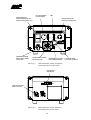
S2
S1
Zündgerät /
Igniter
S1: Ein-Aus / On-Off
S2: Sicherheitsschalter / Safety Switch
H: Stundenzähler / Hours Counter
3
Anschlußbelegung 575 W/
Connector Wiring 575W
Ausgangsbelegung /
Output wiring, lamp
Funktion /
Function
Lampe/
Lamp
ARRI M8 (CCL)
Steckerbelegung /
Connector wiring,
socket
EB 575/800
U-Modul /
U-Module
International
(CIR02R4-2SW)
1
90-130V~
180-250V~
50/60Hz
N
Rechteckwandler /
Square Wave
Converter
Zündzeitbegrenzer
0.75s
IgnitionTime Limiter
Funktionssteuerung/
Function
Control
PE
Abb./Fig. 1b:
Lampe (Hi)/
Lamp (Hi)
C
Zündgerät /
Igniter
Lampe (Lo)/
Lamp (Lo)
D
Zündgerät /
U-Modul
Igniter /
U-Module
F
S2
S1
H
Durchschleifung /
Safety
Loop
A
E
Schutzleiter/
Protective
Earth
G
Frei /
not used
B
Anschlussbelegung 800 W /
Connector Wiring 800 W
- 17 -
S1: Ein-Aus Schalter / On-Off switch
S2: Sicherheitsschalter / Safety Switch
H: Stundenzähler (optional) /
Hours Counter (optional)
LICHTTECHNIK
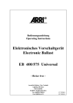
Netzschalter und
Sicherungsautomat 16 A
Mains Circuit Breaker 16 A
Ein-/Aus-Schalter
On-/Off-Switch
LED
Dimmpotentiometer
Dimming Potentiometer
50 Hz
DMX
I
LN
I
PE
60 Hz
LAMP
O
75 Hz
FF
TEMP
LAMP
1000Hz MIN
MAX
O
MAINS
EB 575/800
UNIVERSAL BALLAST
575 W
800 W
Netzkabelanschluß
Mains Supply Cable
Connection
Lampensteckverbinder
Lamp Connector
Abb./Fig. 2:
Nennleistungs-Anzeige
Power Mode Indicator
Bedienelemente auf der Frontplatte
Operating Parts on Front Panel
DMX-Anzeige/
DMX-Display
SIGNAL
ENTER
DMX-Steckverbinder /
DMX-Connectors
DMX IN
Abb./Fig. 3:
DMX OUT
Bedienelemente auf der Rückseite
Operating Parts on Rear Panel
- 18 -
Low Noise Taster
Low Noise Tip Switch