1
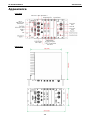
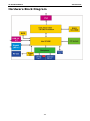
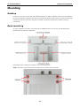
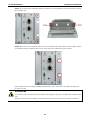
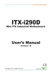
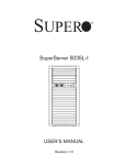
TC-6110 Series Hardware Manual Third Edition, September 2013 www.moxa.com/product © 2013 Moxa Inc. All rights reserved. Reproduction without permission is prohibited. TC-6110 Series Hardware Manual The software described in this manual is furnished under a license agreement and may be used only in accordance with the terms of that agreement. Copyright Notice Copyright ©2013 Moxa Inc. All rights reserved. Reproduction without permission is prohibited. Trademarks The MOXA logo is a registered trademark of Moxa Inc. All other trademarks or registered marks in this manual belong to their respective manufacturers. Disclaimer Information in this document is subject to change without notice and does not represent a commitment on the part of Moxa. Moxa provides this document as is, without warranty of any kind, either expressed or implied, including, but not limited to, its particular purpose. Moxa reserves the right to make improvements and/or changes to this manual, or to the products and/or the programs described in this manual, at any time. Information provided in this manual is intended to be accurate and reliable. However, Moxa assumes no responsibility for its use, or for any infringements on the rights of third parties that may result from its use. This product might include unintentional technical or typographical errors. Changes are periodically made to the information herein to correct such errors, and these changes are incorporated into new editions of the publication. Technical Support Contact Information www.moxa.com/support Moxa Americas Moxa China (Shanghai office) Toll-free: 1-888-669-2872 Toll-free: 800-820-5036 Tel: +1-714-528-6777 Tel: +86-21-5258-9955 Fax: +1-714-528-6778 Fax: +86-21-5258-5505 Moxa Europe Moxa Asia-Pacific Tel: +49-89-3 70 03 99-0 Tel: +886-2-8919-1230 Fax: +49-89-3 70 03 99-99 Fax: +886-2-8919-1231 Table of Contents 1. Introduction ...................................................................................................................................... 1-1 Overview ........................................................................................................................................... 1-2 Model Descriptions and Package Checklist .............................................................................................. 1-2 Appearance........................................................................................................................................ 1-3 LED Indicators .................................................................................................................................... 1-4 Reset Button ...................................................................................................................................... 1-4 Features ............................................................................................................................................ 1-4 Hardware Specifications ...................................................................................................................... 1-5 Hardware Block Diagram ..................................................................................................................... 1-7 2. Hardware Installation ....................................................................................................................... 2-1 Mounting ........................................................................................................................................... 2-2 Desktop ..................................................................................................................................... 2-2 Rack mounting ............................................................................................................................ 2-2 Optional Rack Panel Extender Installation ....................................................................................... 2-4 Wiring Requirements ........................................................................................................................... 2-6 Connecting the Power Supply ............................................................................................................... 2-7 Connecting to a Display ....................................................................................................................... 2-8 Connecting Audio Input/Output ............................................................................................................ 2-9 Connecting USB Devices .................................................................................................................... 2-10 Connecting Serial Devices .................................................................................................................. 2-10 LAN Ports ........................................................................................................................................ 2-11 Installing the SSD/HDD into the Storage Tray ...................................................................................... 2-11 Replacing the Battery ........................................................................................................................ 2-14 Installing System Memory and CF Card ............................................................................................... 2-17 3. BIOS Setup........................................................................................................................................ 3-1 Entering the BIOS Setup Utility ............................................................................................................ 3-2 BIOS Main Page.................................................................................................................................. 3-2 Modifying BIOS Settings ...................................................................................................................... 3-3 Advanced Settings ....................................................................................................................... 3-3 Security Settings ......................................................................................................................... 3-8 Power Settings ............................................................................................................................ 3-9 Boot Settings ............................................................................................................................ 3-10 Exit Settings ............................................................................................................................. 3-12 Upgrading the BIOS .......................................................................................................................... 3-13 A. Safety Installation Instructions ........................................................................................................ A-1 B. Regulatory Statement Approval ........................................................................................................ B-1 1 1. Introduction Thank you for purchasing the Moxa TC-6110 series x86 ready-to-run industrial computer. This manual introduces the hardware installation, connector interfaces, and BIOS setup of the TC-6110. For software configuration and management, please refer to the software manual for your operating system. The following topics are covered in this chapter: Overview Model Descriptions and Package Checklist Appearance LED Indicators Reset Button Features Hardware Specifications Hardware Block Diagram TC-6110 Hardware Introduction Overview TC-6110 train computers are specifically designed for auxiliary train applications such as network video recorders, passenger infotainment systems, condition monitoring, and train-to-ground communications. They come with two Gigabit LAN ports, one RS-232 serial port, three USB 2.0 ports, and two TC-SATA-T storage modules, giving customers a versatile solution for on-board train computing. Providing a high reliability and durable platform for train operation, TC-6110 computers come with M12 connectors for Gigabit LAN ports, USB 2.0 ports, and the dual power inputs. In addition, the expansion modules offer high flexibility for system integration. Users can easily add storage modules for additional data storage capacity, Gigabit switch module to expand connectivity and/or bandwidth, or mini PCIe module for additional peripheral communications. All TC-6110 series computers further come with conformal coating, promising the most reliable operation for component protection under harsh environment. Model Descriptions and Package Checklist The TC-6110 Series includes the following models: TC-6110-W7E: Modular 3U/42HP train computer, Intel Atom D525 1.8 GHz CPU, 4 expansion slots, 24 to 110 VDC isolated power, WLAN module (available on request), Win7 Embedded (32-bit) , -25 to 55°C operating temperature range, compliant with EN 50155 Class T1 TC-6110-T-W7E: Modular 3U/42HP train computer, Intel Atom D525 1.8 GHz CPU, 4 expansion slots, 24 to 110 VDC isolated power, WLAN module (available on request), Win7 Embedded (32-bit), -40 to 70°C operating temperature range, compliant with EN 50155 Class TX TC-6110-CT-W7E: Modular 3U/42HP train computer, Intel Atom D525 1.8 GHz CPU, 4 expansion slots, 24 to 110 VDC isolated power, conformal coating, WLAN module (available on request), Win7 Embedded (32-bit) , -25 to 55°C operating temperature range, compliant with EN 50155 Class T1 TC-6110-CT-T-W7E: Modular 3U/42HP train computer, Intel Atom D525 1.8 GHz CPU, 4 expansion slots, 24 to 110 VDC isolated power, conformal coating, WLAN module (available on request), Win7 Embedded (32-bit), -40 to 70°C operating temperature range, compliant with EN 50155 Class TX TC-6110-LX: Modular 3U/42HP train computer, Intel Atom D525 1.8 GHz CPU, 4 expansion slots, 24 to 110 VDC isolated power, WLAN module (available on request), Linux Debian 7, -25 to 55°C operating temperature range, compliant with EN 50155 Class T1 TC-6110-T-LX: Modular 3U/42HP train computer, Intel Atom D525 1.8 GHz CPU, 4 expansion slots, 24 to 110 VDC isolated power, WLAN module (available on request), Linux Debian 7, -40 to 70°C operating temperature range, compliant with EN 50155 Class TX TC-6110-CT-LX: Modular 3U/42HP train computer, Intel Atom D525 1.8 GHz CPU, 4 expansion slots, 24 to 110 VDC isolated power, conformal coating, WLAN module (available on request), Linux Debian 7, -25 to 55°C operating temperature range, compliant with EN 50155 Class T1 TC-6110-CT-T-LX: Modular 3U/42HP train computer, Intel Atom D525 1.8 GHz CPU, 4 expansion slots, 24 to 110 VDC isolated power, conformal coating, WLAN module (available on request), Linux Debian 7, -40 to 70°C operating temperature range, compliant with EN 50155 Class TX Each model is shipped with following standard items: TC-6110 train computer Rack mount kit Power switch with cable extender M12 connector (M12A-5P-IP68) Power cable (CBL-Power Jack to M12) Documentation CD or DVD Quick installation guide (printed) Warranty card 1-2 TC-6110 Hardware Introduction Appearance Front View Dimensions 1-3 TC-6110 Hardware Introduction LED Indicators LED Name Power LED Color Power is on and functioning normally Off Power is off or power system error System Ready Yellow Tx(P1) Rx(P1) LAN(P1-P2) X1-X4 LED Function Green Logged in to OS, functioning normally Off Login failure or OS not functioning normally Green Serial port P1 transmitting data Off Serial port P1 not transmitting data Yellow Serial port P1receving data Off Serial port P1 not receiving data Green Programmable by users Yellow Programmable by users Off Working 100 Mbps Ethernet link Green Working 1000 Mbps Ethernet link Off Disconnected or short circuit Reset Button The reset button on the TC-6110’s front panel initiates a soft system reboot. Once the system has completed the reboot the Ready LED will maintain a steady glow. Features The TC-6110 computer has the following features: Fanless and rugged design for rolling stock applications Compliant with EN 50121-4 and essential sections of EN 50155 Protective conformal coating to prevent moisture, dust, and corrosion 3U high compact design, 24 to 110 VDC isolated wide range power supply Modular design for easy storage and peripheral expansion Moxa SafeGuard Technology provides: Reliable HDD operation at low temperatures Independent temperature sensor with custom API Independent G-sensor returns system shock/vibration info with custom API SNMP-based system configuration and monitoring supported 1-4 TC-6110 Hardware Introduction Hardware Specifications Computer CPU: Intel Atom D525, dual core 64 bit threaded 1.8 GHz, 1 MB for L2 cache OS (pre-installed): Linux Debian 7 or Windows Embedded Standard 7 System Chipset: ICH8-M System Memory: 4 GB capacity, 2 GB pre-installed: 2 slots of 2 GB DDR3-1066 204 pin SO-DIMM SDRAM USB: 3 USB 2.0 compliant hosts; 2 with type A connectors supporting system bootup, 1 with M12 connector Storage Built-in: 8 GB onboard industrial CompactFlash card for operating system storage HDD Support: 2 removable TC-SATA-T storage trays, for 2.5” SSD or HDD storage drive (with Intelligent Heating Solution) Other Peripherals Audio: 1 line in / line out interface with M12 connector Independent Sensors: Accelerometer (G-sensor), thermometer (T-sensor) Display Graphics Controller: Integrated Intel GMA 3150 (Pineview) Graphics Engine VGA Interface: Up to 2048 x 1536 resolution at 75 Hz, Female DB15 connector Ethernet Interface LAN: 2 auto-sensing 10/100/1000 Mbps ports (M12) GPS Module Receiver Types: 50 channels, GPS L1 C/A code, SBAS (WAAS), EGNOS, MSAS, GAGAN Acquisition: • Cold start: 29 s • Warm start: 29 s • Aided start: 1 s • Hot start: 1 s Sensitivity: • Tracking & Navigation: -160 dBm • Reacquisition: -160 dBm • Cold start: -147 dBm Accuracy: • Autonomous: 2.5 m • SBAS: 2.0 m Protocols: NMEA, UBX binary, max. update rate: 5 Hz (ROM version) Time Pulse: 0.25 Hz to 1 kHz Velocity Accuracy: 0.1 m/s Heading Accuracy: 0.5° A-GPS: AssistNow Online/Offline, SUPL (Open Mobile Alliance) compliant Operational Limits: • Dynamics ≤ 4 g • Altitude 50,000 m • Velocity 500 m/s Connector Type: QMA WLAN Module (Available on request) Standards: IEEE 802.11 a/b/g/n for wireless LAN Security: WEP, TKIP, and AES hardware encryption Antenna Type: 2 QMA connectors (female type) Mode: Client (default), Access Point (available on request) Serial Interface Serial Standards: 1 RS-232 port (DB9 male) Data Bits: 5, 6, 7, 8 Stop Bits: 1, 1.5, 2 1-5 TC-6110 Hardware Introduction Parity: None, Even, Odd, Space, Mark Flow Control: RTS/CTS Baudrate: Up to 115.2 kbps Serial Signals RS-232: TxD, RxD, DTR, DSR, RTS, CTS, DCD, GND LEDs System: Independent "Power" and "System Ready" signals LAN: 100M/Link x 2, 1000M/Link x 2 Serial: TX x 1, RX x 1 Other: Programmable x 4 Physical Characteristics Housing: Aluminum and SECC sheet metal (1 mm) Weight: 5 kg Dimensions: • Without ears: 210 x 222 x 133 mm (8.27 x 8.74 x 5.24 in) • With ears: 210 x 269 x 133 mm (8.27 x 10.60 x 5.24 in) Mounting: Rack Environmental Limits Operating Temperature: • Standard models: -25 to 55°C (-13 to 140°F), (EN 50155 Class T1) • Wide temp. models: -40 to 70°C (-40 to 158°F), (EN 50155 Class Tx) Storage Temperature: -40 to 85°C (-40 to 185°F) Ambient Relative Humidity: 5 to 95% (non-condensing) Anti-vibration: Meets EN 50155 standard Anti-shock: Meets EN 50155 standard Power Reset Button: For warm reboot (front panel) Input Voltage: 24 to 110 VDC, M12 connector Power Consumption: 32 W (without heater), 62 W (with heater), no SSD/HDD attached Note: 24 VDC and 110 VDC compliant with EN 50155 Standards and Certifications Safety: UL 60950-1, CSA C22.2 No. 60950-1-07, EN 60950-1 EMC: EN 55022:2010 Class A, EN 55024:2010, FCC CFR Title 47 Part 15 Subpart B: 2011 Class A, CISPR 22:2008, ANSI C63.4:2009, ICES-003 Issue 5:2012 Class A RF: EN 62311:Jan 2008, ETSI EN 301 489-1:V1.9.2 (2011-09), ETSI EN 301 489-3:V1.4.1 (2002-08), ETSI EN 301 893:V1.6.1 (2011-11), ETSI EN 300 328:V1.7.1 (2006-10), ETSI EN 300 440-1:V1.6.1 (2010-08), ETSI EN 300 440-2:V1.4.1 (2010-08) Rail Traffic: EN 50155:2007, EN 50121-1:2006 for EMC test, EN 50121-3-2:2006, EN 50121-4:2006, EN 5011:2009+A1:2010, EN 61000-6-4:2007, CISPR 16-1-2:2003/A2:2006, CISPR 16-2-1:2003+A1:2005, CISPR 16-2-3:2006, EN 60068-2-1:2007, EN 60068-2-2:2007, EN 61373:1999 Environmental Tests: EN 60068-2-1:2007, EN 60068-2-2:2007, EN 61373:1999 Reliability Automatic Reboot Trigger: Built-in WDT (watchdog timer) supporting system reset with software programmable time intervals of 1-255 Warranty Warranty Period: 3 years Details: See www.moxa.com/warranty Note: These hardware specifications describe the embedded computer unit itself, but not its official accessories. In particular, the wide temperature specification does not apply to accessories such as power adaptors and cables. 1-6 TC-6110 Hardware Introduction Hardware Block Diagram 1-7 2 2. Hardware Installation TC-6110 train computers are specifically design for the applications used on trains. They come with 2 Gigabit LAN ports, 1 RS-232 serial port, 2 USB 2.0 hosts, and 2 expansion slots for inserting various modules, offering an ideal solution for train computing applications. The following topics are covered in this chapter: Mounting Desktop Rack mounting Optional Rack Panel Extender Installation Wiring Requirements Connecting the Power Supply Connecting to a Display Connecting Audio Input/Output Connecting USB Devices Connecting Serial Devices LAN Ports Installing the SSD/HDD into the Storage Tray Replacing the Battery Installing System Memory and CF Card TC-6110 Hardware Hardware Installation Mounting Desktop Place your TC-6110 on a clean, flat, well-ventilated desktop. For better ventilation, leave some space between the TC-6110 and other equipment. Do not place equipment or objects on top of the TC-6110 because this may insulate the heat sink, cause the computer to overheat, and severely damage the computer’s internal components. Rack mounting TC-6110 computers come with a rack mount kit for installation into a 19-inch rack. The following figure illustrates the mounting kit components. Follow these steps to install the computer’s rack mount components. Step 1: Use eight screws to fasten the mounting ears to each side of the computer. 2-2 TC-6110 Hardware Hardware Installation Step 2: If you would like to install the handles, use the four screws provided to secure the handles to each of the mounting ears. Step 3: Place the TC-6110 computer into the rack, and carefully fasten the screws to hold it in place. Please note that the screws for fastening the TC-6110 to the rack are included in the rack mount kit. After installing the rack mounting assembly (handles and/or ears), four screws are required to fasten the TC-6110 to a rack. ATTENTIONS For maximum safety, at least two persons should work together to lift, place, and fasten the computer to the rack. Before you lift or move the computer, first verify both it and any power to the rack system is turned off. 2-3 TC-6110 Hardware Hardware Installation Optional Rack Panel Extender Installation The TC-6110 comes with an optional half-rack extender kit, allowing users to install the (half-rack) TC-6110 computer on a full 19-inch rack. This kit includes the following components. Follow these steps to install the half-rack extender. Step 1: Use four standard screws to install the standard (short) rackmount ear on the computer’s left side. Step 2: Use another four standard screws to install the extension panel on the right side. 2-4 TC-6110 Hardware Hardware Installation Step 3: Remove the two rear-most screws from the right side of the computer. Step 4: Place the support panel so that it abuts the extension panel, with the screw holes aligning with the two flanges on both the panel and the right corner of the computer. Place the toothed locking washer over the screw holes on the computer’s right side, then use the dome headed screws to fasten the support panel to the side of the computer. Step 5: Next, use three flathead screws to fasten the other end of the support to the rear of the extended panel. The screws should penetrate from the front of the extension panel backwards, through the panel support. 2-5 TC-6110 Hardware Hardware Installation Step 6: An additional grounding point is available on the rack extension panel. To use the extension panel’s grounding point, place the mounting ring of the ground wire over the threaded M6 grounding stud. Next, place the flat washer and S-type washer over the grounding stud, and use the M6 nut to fasten the ground wire to the stud. ATTENTION For maximum safety, at least two persons should work together to lift, place, and fasten the computer to the rack. Before you lift or move the computer, first verify both it and any power to the rack system is turned off. You may now install the computer on a full 19” rack. After installing the standard rack mounting assembly (ears, handles), four screws will be required to fasten the TC-6110 to a rack. Wiring Requirements The following common safety precautions should be observed before installing any electronic device: • Strive to use separate, non-intersecting paths to route power and networking wires. If power cables must be laid or mounted across communications cables, make sure the wires are perpendicular and well insulated at the point of intersection. • Keep the wires separated according to interface. The rule of thumb is that wiring which shares similar • Do not bundle input wiring with output wiring. • When necessary, it is strongly advised that you label all wires in the system. electrical characteristics may be bundled together. ATTENTION Do not run signal or communication wiring and power wiring in the same conduit. To avoid interference, wires with different signal characteristics (i.e., different interfaces) should be routed separately. 2-6 TC-6110 Hardware Hardware Installation ATTENTION Safety First! Be sure to disconnect the power cord before installing and/or wiring your device. Caution! High Electrical Current! Calculate the maximum possible current for the diameter of each power wire and common wire. Observe all electrical codes dictating the maximum current allowable for each wire gauge. If the current goes above the maximum ratings the wiring could overheat, causing serious damage to your equipment. Caution! High Temperatures! Be careful when handling the unit. When the unit is plugged in, the internal components generate a lot of heat which may leave the outer casing too hot to safely touch with bare hands. Connecting the Power Supply The TC-6110 computers come with dual (redundant) DC power inputs, 24 to 110 volts each (variable). Refer to the figure at right for the power pin assignment of the power inputs. When setting up TC-6110 computers for testing and/or system development in an office or lab with an AC source, follow these steps to connect the AC power adaptor: Step 1: Connect the exposed ends of the extended power switch cable to the male portion of the 2-pin Euroblock (provided). Step 2: Plug the male Euroblock into the matching female terminal on the front panel. Step 3: Make sure the power switch is turned off (Open, in the diagram below). Step 4: Connect the earth/ground cable to the Phillips-head ground connector on the lower right corner of the front panel. Step 5: Connect the power cable (CBL-Power Jack to M12) to the M12 connector as shown at right. Then connect the power connector to power input 1 on the front panel. Step 6: On the other side of the power cable, connect to the PWR-24250-DT-S1 power adaptor (optional), and a PWC-series power cord (optional). Step 7: To check power redundancy, use the same method to connect the power to the power input 2. Step 8: Switch on the TC-6110 (Short state). If power supply is connected properly, both power input and system power LEDs will be on (green), as well as the yellow Ready LED. 2-7 TC-6110 Hardware Hardware Installation For the TC-6110 computers used in the field site, follow these steps to connect the power: Step 1: Connect the ends of the extended power switch cable to the male portion of the 2-pin Euroblock (provided); you may also choose to not use the cable extender, and connect the switch to the terminal directly. Step 2: Plug the male Euroblock into the matching female terminal on the front panel. Step 3: Make sure the power switch is turned off (Open). Step 4: Connect the earthing/ground cable to the ground connector (Phillips head) on the lower right corner of the front panel. Step 5: Connect the M12 connector to the power cable’s output end using the pin assignment at right. Step 6: Connect this M12 connector to power input 1 on the front panel of the computer. Step 7: Use the same method to prepare a cable for power input 2. Step 8: Turn on the computer. If the power supply is connected properly, the Power and System Power LEDs will be on, and the yellow Ready LED will also be on. If you need to disconnect the power, reverse these steps. ATTENTION Please note that the branch circuit over current protection must be rated maximum 10 A. Connecting to a Display The TC-6110 comes with a female D-sub DE-15 VGA interface on the front panel. To ensure that the monitor connection remains stable, be sure to tighten the plug’s thumbscrews after connecting it to the TC-6110 computer. The location of the VGA connector and pin assignments of the VGA connector are shown below. 2-8 TC-6110 Hardware Hardware Installation DE-15 Female Connector Pin No. Signal Definition Pin No. Signal Definition 1 Red 9 VCC 2 Green 10 GND 3 Blue 11 NC 4 NC 12 DDC2B Data 5 GND 13 HSYNC 6 GND 14 VSYNC 7 GND 15 DDC2B Clock 8 GND Connecting Audio Input/Output The TC-6100 series comes with an M12 audio input/output. See the following figure and table for the pin assignment of the audio jack. Pin Audio 1 Line in-Right 2 GND 3 -- 4 Line in-Left 5 Line out-Left 6 -- 7 Line out-Right 8 GND 2-9 TC-6110 Hardware Hardware Installation Connecting USB Devices The TC-6110 embedded computer has three USB 2.0 ports: two come with type A connectors, and one with M12 connector. All of the ports are UHCI, Rev 2.0 compliant and support Plug & Play and hot swapping. These ports can be used to connect such USB devices as keyboards, mice, USB flash disks, and USB CD-ROMs. In addition, both USB ports support system boot up, which can be activated by modifying the BIOS settings. The chapter USB Configuration in the BIOS Setup chapter describes the configuration process in detail. Refer to the following table for the pin assignment of the USB host’s M12 connector: Pin USB 1 D+ 2 D- 3 +5V 4 GND 5 N.C. Connecting Serial Devices The TC-6110 comes with one DB-9 (male) RS-232 serial interface. The pin assignments for the ports are shown in the following table: The pin assignments for the RS-232 serial port are shown in the following table: Pin RS-232 1 DCD 2 RxD 3 TxD 4 DTR 5 GND 6 DSR 7 RTS 8 CTS 2-10 TC-6110 Hardware Hardware Installation LAN Ports The TC-6110 has two 10/100/1000 Mbps LAN ports with M12 hardware interfaces. When the cable is properly connected, the LEDs on the front panel will glow to indicate a successful link. The tables below show the front panel layout and the pinouts for the M12 Ethernet LAN connector. Pin No. 10/100 Mbps 1000 Mbps 1 – TRD3+ 2 – TRD4+ 3 – TRD4- 4 ERx- TRD1- 5 ETx+ TRD2+ 6 ERx+ TRD1+ 7 – TRD3- 8 ETx- TRD2- These LAN ports use the DHCP for the IP address. Installing the SSD/HDD into the Storage Tray TC-6110 computers come with two storage trays that can be installed with SSD or HDD for storage expansion. Step 1: Remove the storage tray from the computer. Step 2: Remove the six screws that fasten the PCB to the storage tray. These are circled in red, on the figure below. Please note, it is not necessary to remove the remaining three screws. 2-11 TC-6110 Hardware Hardware Installation Step 3: Detach the SATA power and data interfaces from the main board by carefully sliding the tray away from the main PCB. Step 4: Remove four screws on the tray. Step 5: Insert the SSD/HDD into the tray. 2-12 TC-6110 Hardware Hardware Installation Step 6: Turn back the tray and fasten the drive to the PCB using the holes indicated below. Step 7: Fasten four screws on the front. Step 8: Connect the power cable and SSD/HDD cable with the main board. Reconnect the data and power interfaces, then complete the installation by fastening the drive tray to the main PCB using the six screws. Step 9: When finished, insert the storage tray back into the TC-6110 and tighten the external thumbscrews. 2-13 TC-6110 Hardware Hardware Installation Please note that on each removable drive module there is a hot-swap button and four LED indicators. To hot swap storage drives users will need to first install the Moxa hot swap software package, as described in the TC-6110 software manual. Once installed, to hot swap a drive users must use a sharp object to push the hot swap button (X1, on the front panel map) and wait until the L1 LED indicator goes dark, indicating the drive has unmounted and is ready for extraction. The L3 and L4 LEDs are programmable, to be defined by users. Refer to the software manual for more details about the Moxa hot swap software package and programming the LEDs. The following table describes the functions associated with each LED and button. LED Indicator/Button Function L1 L2 On HDD is accessing data Off No activity Blinking Heater is on in specific environments. Refer to the following conditions: Below 55℃ when power is available. Below 15℃ when system is on. Off Heater is off L3 Defined by admin L4 Defined by admin X1 hot-swap button, for unmounting drives Replacing the Battery TC-6110 computers come with an internal battery that provides power for the built-in RTC. To replace the battery, follow these steps. Step 1: Remove the four screws on the front panel of the computer. Step 2: Remove the six screws from between the computer’s longest heat-sink fins. 2-14 TC-6110 Hardware Hardware Installation Step 3: Turn to the computer backside-front, and remove the two screws fastening the large heat sink to the rest of the computer (indicated below). It is not necessary to remove the other screws. Step 4: To get access to the interior of the TC-6110, slide the large heat sink / main interface module in one direction, and the rest of the unit in another. Step 5: Place the module so it is sitting with the heat sink face down, and remove all seven screws from the rear of the module. These screws hold the main interface module in place. 2-15 TC-6110 Hardware Hardware Installation Step 6: In addition, you will need to release all hardware interfaces from the front plate of the main interface module. These are two panel screws, four screws holding the D-Sub connectors in place, and the four rings that fasten the four M12 connectors in place (audio, USB, and two LAN ports). These are all shown below. Step 7: Finally, a single screw on either side of the heat sink also needs to be removed. Step 8: Once all screws have been unfastened, gently push the cover to the left to reveal the battery’s location. 2-16 TC-6110 Hardware Hardware Installation Step 9: Use a small screwdriver or other tool to release the clutches on the battery socket, and remove the old battery. Gently place the new battery into the socket. Step 10: When finished, reverse the steps above to rebuild the TC-6110 unit. Installing System Memory and CF Card The TC-6110 computer comes with two system memory sockets; one of these is pre-installed with 2 GB of memory. In addition, an 8 GB CompactFlash card has also been pre-installed. Follow the steps below to add or replace either the system memory or the CF card. Refer to Steps 1 through 8 in the section, Replacing the Battery; then follow the steps below. Step 9: Remove the seven brass standoffs on the upper main board. Step 10: Gently remove the upper main board, and then locate the system memory and CF socket. 2-17 TC-6110 Hardware Hardware Installation Step 11: A) To remove the memory cards: Push the two clutches on either side of the socket outwards, to free the memory, and then carefully remove the card. Install the new memory into the slot. Make sure you install it in the correct direction, and then push it down to complete the installation. B) To remove the CompactFlash card: Gently lift the plastic cradle holding the CF card, and then slide the card out. After inserting a replacement, gently push the cradle downwards, being careful not to bend the interface pins. Reverse steps 9 to 1 to rebuild the unit and complete the system memory and CF card installation. 2-18 3 3. BIOS Setup This chapter describes the BIOS settings of the TC-6110 computer. The BIOS is a set of input/output control routines for peripherals. The BIOS is used to initialize basic peripherals and loads the operating system. The BIOS setup allows the user to modify the system configurations of these basic input/output peripherals. All of the configurations will be stored in the NVRAM (flash memory), which retains the system information after system reboots or the power is removed. The following topics are covered in this chapter: Entering the BIOS Setup Utility BIOS Main Page Modifying BIOS Settings Advanced Settings Security Settings Power Settings Boot Settings Exit Settings Upgrading the BIOS TC-6110 Hardware BIOS Setup Entering the BIOS Setup Utility To enter the BIOS setup utility, press the “F2” key while the system is booting up. The main BIOS Setup screen will appear. A basic description of each function key is listed at the bottom of the screen. Refer to these descriptions to learn how to use them. F1: General Help ↑↓: Select Item F5/F6: Change Values ← →: Select Menu F9: Setup Defaults ESC: Exit F10: Save and Exi ENTER: Select or go to Submenu BIOS Main Page The main page of the BIOS displays basic low-level information about system hardware, including things like model names, CPU type, and BIOS version. 3-2 TC-6110 Hardware BIOS Setup Modifying BIOS Settings Navigate the BIOS menus using the arrow keys; up (↑) and down (↓) arrows navigate the menu, while left (←) and right (→) arrows will open or close sub-menus from entries marked with a triangle (▲) at the beginning of the line. Advanced Settings The “Advanced Features” screen will appear when choosing the “Advanced” item from the main menu. Boot Configuration This item allows users to toggle the number pad into “on” or “off” when first booting up. 3-3 TC-6110 Hardware BIOS Setup Peripheral Configuration The Serial Port A item under Peripheral Configuration allows you to select the serial port. Options: 3F8/IRQ4, Disabled (default) IDE Configuration This item allows you to configure the storage drive controllers. HDC Configure As This item allows you to configure the storage drive type. The options are: 3-4 TC-6110 Hardware BIOS Setup AHCI (default); PATA; SATA; and IDE Non-Combined Channel Master 1 to 3 This setting displays the storage devices installed on the computer’s master bus. These storage devices may be DOMs, HDDs, SSDs, or a CF card. Channel Slave 1 to 3 This setting displays storage devices installed on the computer’s slave bus. These storage drives may be DOMs, HDDs, SSDs, or a CF card. Video Configuration This item allows you to configure the video settings. IGD – Pre-Allocated This item allows you to configure the pre-allocated capacity for the graphic memory capacity. Options: 8 MB (default), 1 MB IGD – DVMT Size This item allows you to configure the capacity of the DVMT 5.0 used by the internal graphics device. Options: 64 MB (default) , 128 MB, 224 MB 3-5 TC-6110 Hardware BIOS Setup USB Configuration This item allows you to turn USB Legacy mode on or off. USB Legacy allows older USB devices to be accessed from the earliest boot initialization, and/or DOS. Options: Enabled (default), Disabled ACPI Table/Features Control This item allows you to configure the HPET functions. HPET – HPET Support 3-6 TC-6110 Hardware BIOS Setup This item allows you to enable/disable the HPET (High Precision Event Timer), which produces periodic interrupts at a much higher resolution than the RTC and may be used to synchronize multimedia streams. HPET can sometimes introduce system instability, so some users may wish to disable it. Option: Enabled (default), Disabled Base Address Select This allows you to select the memory address range for the HPET. Options: FED00000h (default), FED01000h, FED02000h, FED03000h Hardware Monitor This item allows you to view various self-reported hardware states that include CPU temperature, system temperature, and CPU voltage. Please note that at 100°C the accuracy of CPU temperature readings are in the range of -5°C to +10°C. This deteriorates to -10°C to +15°C at 50°C. The CPU temperature readings saturates at some point below 50°C. Any CPU reading below 50°C is unreliable, and may only be interpreted as indicating a temperature below 50°C. 3-7 TC-6110 Hardware BIOS Setup Security Settings The section allows users to configure security settings like a system supervisor password and user password. Set Supervisor Password This item allows you to set the supervisor password. Select and then enter the password, and then confirm the password again. Set User Password This item allows you to set the user password. Select and then enter the password, and then confirm the password again. Set All HDD Password This item allows you to set the password for all storage devices on your computers, including CF, DOM and hard disk. You need to enter the password when booting up to use these storage devices. Please note that to update the password you need to first enter the current password, and then enter a new password. If you wish to simply cancel the password and leave the system unprotected, you may leave the password update box blank but Moxa strongly recommends against this. WARNING To guarantee your hard drive remains accessible, remember to record your hard disk drive passwords in a secure place for future reference. If you set a security password on your hard drive you will need to enter the same password whenever you access it, even if it is transferred to another computer. 3-8 TC-6110 Hardware BIOS Setup Set All Master HDD Password This item allows you to set the password for the master storage drive on your computer. You need to enter the password when booting up to use the master hard disk. Power Settings The section allows users to configure power settings. Advanced CPU Control Thermal Mode This item enables Intel’s thermal throttling 1 technology in the CPU; it functions as a temperature trip that will throttle the CPU (and thereby decrease performance) when a certain temperature is reached. Enabling this function allows you to configure the thermal control circuit in the operating system userspace. Options: TM1 (default), Disabled HT Support: Hyper-Threading Technology This item enables Hyper-Threading (HT) technology, so that the CPU may utilize simultaneous multithreading. This improves performance for multi-threaded code and gives improved reaction and response time. However, in some instances users may want to disable it to conserve power or reduce CPU cache paging. Options: Enable (default), Disabled Use XD Capability This item allows you to enable/disable the Intel XD function, which provides executable space protection by toggling the NX bit in memory spaces designated as data. This gives a strong protection against buffer 3-9 TC-6110 Hardware BIOS Setup overflows by preventing the execution of malicious code that has been delivered into memory space in a hidden data packet. Options: Disabled (default), Enable Boot Settings The section allows users to configure boot settings. UEFI Boot This item allows you to enable/disable the Unified Extensible Firmware Interface, which allows for remote diagnostics and repair of computers even without an operating system. Users who are concerned about safety or ownership issues may disable it. Options: Enabled (default), Disabled Quick Boot This item allows you to enable/disable quick book function to reduce OS loading times. Options: Enabled (default), Disabled PXE Boot to LAN This item allows you to configure the Preboot eXecution Environment‘s boot-to-LAN function. PXE provides an independent boot environment that may be initialized over a network interface, without intermediary storage devices or local operating systems. Options: Disabled (function), enabled USB Boot This item allows you to enable/disable the system to boot from a USB storage device or network connection. Options: Enabled (default), Disabled 3-10 TC-6110 Hardware BIOS Setup EFI This item displays the boot selection for the UEFI boot function. Legacy Normal Boot Menu This item allows you to configure the boot menu. Options: Normal (default), Advanced Boot Type Order This item allows you to select the order in which the computer will search storage devices for bootable images; the highest device on the list will be searched first, then the second, and so on until the computer finds a bootable image. F5/F6 will allow you to change the boot order. Options: Hard Disk Drive (default), CD/DVD-ROM Drive, USB, Others. Hard Disk Drive This item allows you to view information returned by the storage device (SSD, HDD) installed in the computer. USB This item allows you to view information about any USB device connected to the computer. 3-11 TC-6110 Hardware BIOS Setup Exit Settings The section allows users to exit the BIOS. Exit Saving Changes This item saves the values you have just configured and exits the BIOS. Options: Yes (default), No Save Change Without Exit This item saves changes but does not exit the BIOS. Options: Yes (default), No Exit Discarding Changes This item allows you to exit the BIOS without saving any new settings from the user session. Options: Yes (default), No Load Defaults Setting This item resets the entire BIOS to factory default values. Options: Yes (default), No Load Custom Defaults This item loads custom defaults across the entire BIOS. Options: Yes (default), No 3-12 TC-6110 Hardware BIOS Setup Save Custom Defaults This item saves the current BIOS settings as the new custom defaults. Options: Yes (default), No Discard Changes This item allows you to discard all settings you have just configured. Options: Yes (default), No Upgrading the BIOS This section describes how to upgrade the BIOS. However, please note that it is easy to permanently damage the computer when upgrading the BIOS. We strongly recommend that you contact Moxa’s technical support staff for assistance in order to obtain all necessary tools and the most current advice before attempting to upgrade the BIOS on any Moxa device. Step 1: Create a Bootable USB Disk. Before upgrading the BIOS every user should first create a bootable USB RAM drive as a system rescue device. A useful software suite for building USB RAM drives may be found by searching for HP USB Disk Storage Format Tool, which may then be downloaded and used to create a bootable RAM drive. To create a rescue system, you will also need to download the FreeDos system files kernel.sys and command.com from http://www.freedos.org/kernel/. Copy the DOS files kernel.sys and command.com to a specified directory (C:\FreeDOS in this example). Start the HP USB Disk Storage Format Tool and in the drop-down menu labeled Device select the USB device that you want to use as a bootable disk. Configure it to use a FAT file system from the File System drop-down. Enter a drive name in the Volume Label field. Check the option Create a DOS Startup Disk under Format Options. Specify the directory where the system files are located (for example, C:\FreeDOS). Click Start to format and create the bootable USB drive. 3-13 TC-6110 Hardware BIOS Setup ATTENTION We suggest you use a USB drive with under 2 GB of disk space, as larger USB drives may not support the FAT file format and will consequently fail to boot. Step 2: Prepare the Upgrade File. You must use the BIOS upgrade installation file to upgrade the BIOS. You can send your request to Moxa's technical support team at [email protected] to get an updated version of the BIOS. 1. Get the BIOS upgrade installation file. The file name should have following format: 6110xxSxx.exe (xx refers to version numbers) 2. Copy the file to the Bootable USB Disk. Step 3: Run the upgrade program on the TC-6110 computer 1. Reboot the computer and go to the Boot Manager by pressing F12 while booting up, before the operating system has begun to load. 2. Select USB Disk as the first boot source. Press Enter to continue. 3. Once the computer boots, a DOS screen will appear. Go to the directory where the upgrade file is located. For example, if the upgrade file is stored in the TC6110 folder, type: C:\ cd TC6110 4. Run the upgrade program by typing: C:\ TC6110>611010S05.exe Please note that the upgrade filename may vary depending on the firmware version. 5. The upgrade program will run. Wait until the procedure is finished before initiating any changes to the system. Be patient; the upgrade will take quite a few minutes. DO NOT ALLOW THE COMPUTER TO POWER DOWN! DO NOT REMOVE THE USB DRIVE! 3-14 TC-6110 Hardware BIOS Setup 6. Once the upgrade is finished, the computer will automatically reboot. To check and see if the upgrade was successful, navigate to the BIOS Main Page and note the BIOS Version number. ATTENTION Do NOT switch off the power supply during the BIOS upgrade. Doing so will likely cause permanent damage to your system! 3-15 A A. Safety Installation Instructions A. RTC Battery Warning CAUTION: There is a risk of explosion if battery is replaced by an incorrect type. Dispose of used batteries according to the instructions. B. Fuse Warning CAUTION: For continued protection against fire, replace only with same type and rating of fuse. C. Rack mount Warning The following or similar rack mount instructions are included with the installation instructions: (1) Elevated Operating Ambient: If installed in a closed or multi-unit rack assembly, the operating ambient temperature of the rack environment may be greater than the room ambient temperature. Therefore, consideration should be given to installing the equipment in an environment compatible with the maximum ambient temperature (Tma) specified by the manufacturer. (2) Reduced Air Flow: Installation of the equipment in a rack should be such that the air flow required for safe operation is not obstructed. (3) Mechanical Loading: Mounting of the equipment in the rack should not create hazards that result from uneven mechanical loading. (4) Circuit Overloading: Consideration should be given to the connection of the equipment to the power supply and the effect that overloading of the circuits might have on overcurrent protections or supply wiring. Appropriate consideration of equipment nameplate ratings must be noted when evaluating this concern. (5) Reliable Grounding: Reliable grounding of rack-mounted equipment should be maintained. Particular attention must be given to indirect power connections that do not directly link to the branch circuit (e.g., over power strips). D. High Temperature Warning (1) This equipment is intended to be used in a Restricted Access location like a locked computer room. Access to this equipment should only be granted to AUTHORIZED SERVICE PERSONNEL or to users who have been instructed about the the potential heat hazard posed by the metal chassis. This computer can become so hot that after a long period of operations users and service personnel must take special care to wear protective clothing before touching it. Only AUTHORIZED PROFESSIONALS should be allowed direct access to an operating device. (2) External metal parts can get dangerously hot!! Before touching it, give special attention to device temperature! Protective wear will likely be necessary! B B. Regulatory Statement Approval This device complies with part 15 of the FCC Rules. Operation is subject to the following two conditions: (1) This device may not cause harmful interference, and (2) this device must accept any interference received, including interference that may cause undesired operation. Class A: FCC Warning! This equipment has been tested and found to comply with the limits for a Class A digital device, pursuant to part 15 of the FCC Rules. These limits are designed to provide reasonable protection against harmful interference when the equipment is operated in a commercial environment. This equipment generates, uses, and can radiate radio frequency energy and, if not installed and used in accordance with the instruction manual, may cause harmful interference to radio communications. Operation of this equipment in a residential area is likely to cause harmful interference in which case the user will be required to correct the interference at his own expense. European Community Warning: This is a Class A product. In a domestic environment this product may cause radio interference in which case the user may be required to take adequate measures.