1
www.extron.com
TM
Issue 13.2
April – June 2002
Extron at InfoComm
Connecting with A/V Professionals
The Extron
tradeshow
booth at
InfoComm 2001
FEATURE ARTICLE
On the cover...
Extron at InfoComm
COLUMNS
5
The Extron Hotline:
I-Demos
6
Marketing Matters:
Winning the Price War
without Loosing it too
10 Unique Techniques:
Digital Sync Validation Processing
(DSVP™)
12 Technically Speaking...
IR Control — The Invisible
Frontier
16 Tech Corner:
Tri-Level Sync in a Bi-Level World
20 Featured Product:
ISM Series
ALSO IN THIS ISSUE
7
New Products
18 New News
24 Tweeker Use
I
t is time to gear up for our biggest tradeshow of the year—InfoComm
2002. Extron will unveil dozens of new products, present educational
courses, and cut loose with you at the Extron 2002 Rock & Rodeo Bash!
InfoComm is a great place for Extron to
keep you, our dealers, consultants and
endusers, informed about the latest
innovations and technologies in A/V, as well
as meet with you personally. All of which
enables us to provide the best Service,
Support, and Solutions - S3.
On the Show Floor
This year, we will utilize 6,000 square feet
of booth space to display a wide array of
new products as well as selected items from
our line of interfacing, switching,
distribution, signal enhancement, and cable
products. There will also be working
demonstrations that emphasize real-life
applications and innovative solutions using
new and existing Extron products.
In addition, the new Extron 2002-2003
Product Catalog will be available in our
booth, complete with the New Products
Brochure, which highlights all the new
products introduced at the show. As always,
your Customer Support Representatives,
and Extron’s Product Managers and
Management will be on hand to answer
any technical questions and provide you
with information and literature about
Extron technologies and products.
continued on page 2
Extron at Infocomm (cont.)
EXTRON SEMINARS
Topics of the special Extron Seminars for Extron
dealers @ InfoComm courses include:
• Financing Business Growth
Hosted by Andrew Edwards, President of Extron
Electronics
Instructors:
Howard Edwards, Managing Director for Commercial
Banking Consultants
Ed Ellingwood, Vice President of Finance for Extron
Electronics
Andrew's seminar is designed for the CFO or financial decision
maker of A/V dealerships. Credit and banking are two of the
most important if not THE most important areas of information
needed to run a business. This seminar is not only about how to
work more effectively with Extron credit, but with any
manufacturer in the A/V industry. If you are responsible for the
financial decisions of your dealership you should attend this
seminar. If you own a large dealership, bring your CFO with you.
If you are NOT a large dealer with an official CFO, it is even
MORE important for you to attend this seminar and bring
whoever is responsible for financial and accounting decisions.
Howard's section will focus on financial relationships and provide
unique insight about SBA Loans, credit ratings, credit lines, and
how banks evaluate businesses from the banker’s perspective.
This section will cover information that financial institutions do
not want you to know about how they measure and evaluate
your risk and make decisions about how much credit you
qualify for. Find out which ratios are most important, historical
performance indicators, and the strength of a company’s
financial forecasting methods.
Extron’s booth
location at
Infocomm 2002
show floor.
In the Classroom
We will be conducting nine courses at InfoComm
in conjunction with the InfoComm Academy as well
as four special Extron Seminars for Extron dealers and
consultants only at the Venetian Hotel, Room #901.
In each of the courses, Extron instructors will apply
their in-depth knowledge and expertise gained from
past experience working in the A/V industry and from
extensive interaction with A/V professionals in our S3
Technical Institute. This allows them to present course
material from a perspective that facilitates a better
understanding of the subject matter.
To register for InfoComm Academy/Extron courses
or to view a complete course description, refer to the
recent Extron at InfoComm 2002 Pre-show Mailer
sent to your company or visit the InfoComm Web site
at www.infocomm.org. To register or learn more
about Extron Seminars, call your Extron Regional Sales
Manager at 714.491.1500 or 800.633.9876 (inside
USA and Canada only) or refer to the Extron at
InfoComm 2002 Pre-Show Mailer.
2
ExtroNews 13.2
April – June 2002
Ed’s section will cover the credit element of dealer/ manufacturer
relationships. Learn how Extron and manufacturers in the A/V
industry evaluate a dealer’s credit worthiness and what they look
for when deciding on raising or lowering lines of credit.
• Small System Technologies
Instructor: David Kroeger, Extron West/Canada Regional
Applications Specialist
Explores issues and provides solutions affecting small A/V systems
such as programming concerns, expanding display input limitation,
audio control and enhancement, installation and mounting
concerns, as well as display, room, and device control.
• Advanced Switching Methods
Instructor: Karl Rosenberg, Extron Mid-Atlantic Regional
Specialist
Provides an in-depth look at the latest technologies driving high
performance switching applications including seamless video
switching, vertical interval switching, and genlocking of
equipment.
• Understanding Digital Video Signal Distribution
Instructors: Rich Hanna, Extron Southeast Regional
Applications Specialist
Provides an in-depth look at digital video signal technologies
including signal types, signal composition, specifications, and
integration using the latest distribution technologies.
INFOCOMM ACADEMY / EXTRON CLASSES
Topics for the 2002 InfoComm Academy/Extron classes include:
• The Truth About Scan Converting
Instructor: Chris Gillespie, Extron Technical Trainer
Provides a basic overview of the video signal hierarchy, explains how a scan converter works, goes over the pros and cons of various decoding
technologies, and points out what features need to be considered when selecting a scan converter.
• Terminating Cable Correctly and Efficiently
Instructor: Dennis Olson, Extron Southwest Regional Applications Specialist
Teaches proper cable termination techniques as well as cable testing procedures and provides hands-on experience and exposure to crimping,
soldering, and testing of numerous cable and connector types.
• Display Evaluation Essentials
Instructor: Steve Somers, Extron Vice President of Engineering
Provides essential knowledge about the basic performance attributes of the various display technologies and tools needed to interpret what is
seen in a display demonstration including how to use basic display test patterns to identify performance issues quickly.
• Understanding Video Bandwidth
Instructor: Rich Hanna, Extron Southeast Regional Applications Specialist
Shows how to define, calculate, and measure signal and system bandwidth while providing information about equivalent bandwidth specification
for cable, test generators, and graphic cards.
• The Cable Seminar
Instructor: Chris Gillespie, Extron Technical Trainer
Provides practical knowledge about selecting the correct cable type for specific installations, as well as an understanding of cable construction,
electrical characteristics, and how cables affect system performance.
• An Overview of Integrating IP Into Today’s A/V Systems
Instructor: Chris Gillespie, Extron Technical Trainer
Provides information on applications and benefits of Internet Protocol (IP), networking, streaming media, and traditional control architectures
used in A/V systems.
• Understanding Digital Visual Interface (DVI) Technology
Instructor: Roy A. Hermanson, Jr., Extron Northeast Regional Applications Specialist
Introduces the basics of DVI, reasons for this new technology; DVI specifications, as well as operation, and integration issues.
• Video Over Twisted Pair (CAT 5e/6)
Instructor: Dennis Olson, Extron Southwest Regional Applications Specialist
Explains the ins and outs of using Category 5e/6 cabling for running video and audio signals. Also covers key points such as NEXT, FEXT, skew,
and attenuation as well as misconceptions about this medium.
• Computer Video Interfacing to Presentation Systems
Instructor: Chris Gillespie, Extron Technical Trainer
Provides practical knowledge about interfacing to display systems, beginning with the basics: computer and signal types, bandwidth, how
interfacing works, an overview of interfacing elements such as resolutions, scan frequencies, video and computer standards, and more.
continued on next page
April – June 2002
ExtroNews 13.2
3
Extron at Infocomm (cont.)
INFOCOMM/Projection Shoot-Out
DVD – Volume One
The Demonstration and Evaluation Standard
Wednesday,
June 12, 2002
Rock & Rodeo Bash 2002
It is also time once again for one of InfoComm’s most anticipated events,
the Extron Party. Taking place on Wednesday, June 12, 2002, at a yet
undisclosed location, the party provides an excellent
opportunity for our invited guests to network with
their peers and mingle with their Extron
representatives as well as enjoy great food, drinks,
and entertainment. The party also allows us to show
our appreciation to our dealers, consultants, and
users who support us and our products throughout
Doo-Wah Riders
the year. There will be both rock and country music
live bands entertaining you in a unique, dual-venue
facility. The Zippers are a flashy combination of classic
rock, R&B, disco and swing, while the Doo-Wah
Riders perform a unique blend of country music with
a Cajun twist. In addition, the traditional Battle of the
Bands will take place with confirmed musical groups
The Zippers
from Christie Digital, and NEC.
Events & Activities:
• Carnival-style gaming booths including slap-shot hockey, rodeo ropers,
mechanical bulls, robo-surfer, a rock wall, golf driving ranges, pool
tables, and more!
• Airbrush tattoo artists on hand so you can get ‘inked’
• Photographers so you can commemorate this event with a
complimentary photo button of you with your friends or your favorite
Extron representative
Transportation & More Info
Transportation will be provided to and from the Sands Convention Center
and various hotels and casinos to the Extron Bash. For additional
information about the party, contact your Extron Support Representative at
714.491.1500 or 800.633.9876.
We hope to see you there!
4
ExtroNews 13.2
April – June 2002
The InfoComm/Projection Shoot-Out DVD –
Volume One, entirely produced and distributed by
Extron Electronics in partnership with ICIA, is full of
unique and interactive features. The DVD itself is a
hybrid of a new set of stunning computer-based, multiresolution images, high quality royalty-free video
montages (in both NTSC and PAL) great for product
demonstrations, tradeshows, and shoot-outs; set-up
test patterns; and background music. It includes several
customized enhancements such as image sequencing
and Business Card software that allows a user to insert
a personalized slide with text and logos into a
presentation. Multi-system operation of the DVD is
made possible via Ethernet control. Up to three
computers can run the software at the same or
different resolution. Copies of the software must be
purchased for each computer used. Best of all,
the InfoComm/Projection Shoot-Out DVD – Volume
One allows dealers and technicians to stage their own
shoot-outs.
New Features:
• DVD-based product (hybrid format)
• Montage of royalty-free video imagery in both
NTSC and PAL
• Computer-based, multi-resolution image files
• Network capability for the computer-based files
• Background music selections for computer-based files
• Customizable sequencing
• Educational pop-ups for describing image details
• Personalized “Business Card” feature
• Separate title containing test patterns for setup
• Compatible with previous Shoot-out CD-ROMs
THE
EXTRON
HOTLINE
by Jeff Gibson, Vice President of Sales
I-Demos: Your Virtual Extron Instructor
W
hile installation manuals are sufficient for most products, there
are times when a more personal, hands-on presentation would be
ideal. And, although we’d really enjoy providing in-person, individual
instruction to each Extron dealer, this is not always very timely or practical.
So what’s the solution?
Extron introduces I-Demo— streaming
video demonstrations that focus on the
installation of Extron products. I-Demos were
created to eliminate the guesswork when
installing or mounting these unique Extron
products.
Hideaway Surface Access
Enclosure Installation I-Demo
Connectors can be accessed when needed
by simply pushing down on the top of the
enclosure so that it pivots or vertically lifts
open. To learn more about the HSAs visit the
Extron Web site (www.extron.com) and be
sure to check out the new I-Demo for
installation hints and tips.
An Extron I-Demo walks viewers through
an installation step-by-step, thoroughly
covering safety issues, tools needed, site
preparation, installation of the various
components, and troubleshooting the
finished job. Like Extron E-Demos, I-Demos
enable Extron customers to learn about our
products without leaving the comfort of their
computer. Perfect for one-on-one learning or
for group training presentations, I-Demos
bridge the gap between installation manuals
and live classes. In addition, since I-Demos
can be accessed from any computer through
download or via the Internet, they can be
pulled up at the installation site if a question
should arise.
To view the HSA I-Demo, Windows ®
Media Player is required. This is available for
free download via the internet. There are
three versions of the HSA I-Demo for viewing
online: low speed for use with a 56.6 kbps
dial-up modem or 100k and 300k high speed
versions for broadband connections. There is
also a version that can be downloaded to
your computer’s hard drive. The complete
installation video can be watched in
sequence as each chapter will automatically
launch into the next. Chapters can also be
viewed out of sequence so that needed
information can be accessed quickly
and easily.
The first products to be featured in an
Extron I-Demo are the HSA 400/402 and
HSA 800/802 Hideaway Surface Access
enclosures. HSAs are designed for
inconspicuous computer-video interface
connector access and control and can be
easily integrated into virtually any table
surface. Once installed, HSAs fit flush with
the tabletop, hiding connectors out of sight.
Of course, Extron Customer Support is
always available to answer product,
installation, and technical questions,
24 hours a day, 7 days a week at:
Extron USA: 800.633.9876 or 714.491.1500;
Extron Europe: +31.33.453.4040 or
+800.3987.6673;
Extron Asia: +65.6383.4400;
Extron Japan: +81.3.3511.7655.
April – June 2002
ExtroNews 13.2
5
MARKETING
MATTERS
by Lee Dodson, Vice President of Marketing
Winning the Pricing War
without Losing it too
P
ricing strategy is often at the heart of every company’s competitive
business plan. It’s a well-known fact that the winner of any looming
price war is usually the customer as prices creep downward.
Occasionally, as the battle intensifies, lower and lower prices translate
into lower profits for all competing parties.
Aggressive competitors become so intent on
winning the sale that they lose track of the
bigger picture. On the surface, it may seem like
the customer is the winner. Upon closer
inspection, however, it may become all too
apparent that the so-called “winner” of a sale is
not making enough to even support the
customer after the initial transaction. At that
end, a customer “wins” a low-priced system
that may not be fully engineered, installed
correctly, set up completely, or doesn’t work
from a company that can’t afford to fix it. In our
high-tech A/V industry, this can spark a
disastrous wave of devastating consequences.
Price vs. Value
Continuing cycles of price wars erode a
dealer’s ability to add value to the sale of
products as their margins evaporate. In the
commodities industry where only the slimmest
survive, that may be an effective strategy;
however, the professional A/V industry plays by a
different set of rules. Success is heavily reliant
upon highly trained integrators who sort through
countless options and mix and match the best
combination of products to suit the application.
This sounds simple enough until you are
facing a price war of your own. Often, a priceaggressive competitor is using his or her
strongest (and possibly only) weapon against
you: price. All too often, this is someone with
far less overhead and very little value to offer to
their customers; their only recourse is a lower
price. If you are facing this threat the last thing
you want to do is lower your prices to the point
of losing money. This practice may work for
strategic projects where you bet on a long term
payoff, but certainly not for day-to-day
operations. If not controlled, it’s a surefire way
to go out of business.
Fighting competitors on their own turf can
take its toll. For all the value your firm may offer
in service and support, your competitor with
6
ExtroNews 13.2
April – June 2002
less to offer must ALWAYS reciprocate by being
less expensive than you. If you lower your price
to match theirs, you can bet they will lower
theirs to be considerably less because they
simply have nothing else to offer.
The Value of Value
The trick is to know how much the value you
add is worth. There is a buffer that can be
added in light of these services to keep you
profitable and keep your competitor from
dropping prices even lower. It begins by
identifying your competitor’s weaknesses.
There is a section from the famous ancient
Chinese text, The Art of War by Sun Tzu,
which states:
If you know the enemy and know yourself,
you need not fear the result of a hundred
battles. If you know yourself but not the
enemy, for every victory gained you will also
suffer a defeat. If you know neither the enemy
nor yourself, you will succumb in every battle.
The lesson contained herein lies in
comparing your services and value-added to
that of your competitor. In short, you should
know what you are up against. You must
consider how much your customer is willing to
pay for those extras. Services, experience,
certifications, capacity, turn-around time,
installation skill, inventory, and all other areas
you invest in must carry the kind of value that
customers will seek out and pay for. All you
need is an accurate assessment of the
differences between what you offer and what
your competitor offers. Then, of course, you
need to quantify it and communicate that
message to your customer.
This strategy may not win every sale in a
fierce price war, but if your goal is to stay
profitable and win repeat customers, you will
be on the right track.
N E W P R O D U C T S R E C E N T LY I N T R O D U C E D F R O M E X T R O N
AAP 301 &
AAP 302
Full Rack Width, 1U and
2U Faceplate
AAP 301
AAP 302
AAP
Silk-Screened
Panels
Silk-Screened Architectural
Adapter Plates
Crestron
TPSBLOCK-10
AAP Panels
The Extron AAP (Architectural Adapter
Plate) 301 and 302 are 1U and 2U high, full
rack metal panels that support the
installation of AAP panels into a rack as a
single unit. The AAP 301 has four double
space AAP openings that can be populated
with up to eight single space AAPs or four
double space AAPs. The AAP 302 has four
AAP openings that can be populated with up
to 16 single space AAPs. AAP openings
enable integration with a number of Extron’s
Architectural Adapter Plates. Blank AAP
panels are included to fill unused openings.
Both the AAP 301 and AAP 302 are available
in gray only.
The Extron AAP (Architectural Adapter
Plate) Silk-Screened Panels consist of labeled
single and double space AAPs with standard
inputs. The silk-screened labels reflect the
most commonly used input connector
combinations, enabling clear identification of
RCA (video and audio), 3.5 mm audio,
15-pin HD, 4-pin mini DIN, and BNC
connectors. All AAP Silk-Screened Panels are
available in gray, black, and white.
These new Extron Architectural Adapter
Plates (AAPs) enable mounting of the
Crestron TPSBLOCK-10 Panel Mount
Interface (available only from Crestron) for
Cresnet touch panel connection. There are
two models of the double space AAPs: one
allows for mounting of a single
TPSBLOCK-10 connector, the other allows
for mounting of two TPSBLOCK-10
connectors. The single and dual Crestron
TPSBLOCK-10 AAPs are available in gray,
unpainted, black, and white.
AAP 301 & AAP 302
AAP 301
Part Number
60-459-01
List Price:
$150.00*
AAP 302
Part Number
60-459-02
List Price:
$200.00*
URL
www.extron.com/aap301
www.extron.com/aap302
* Prices listed in US Dollars, valid for US sales only.
AAP Silk-Screened Panels
Call Extron for part numbers and pricing.
URL
www.extron.com/aapsilkscreen
Crestron TPSBLOCK-10 AAP
Single Crestron TPSBLOCK-10 AAP
Part Number
70-195-01 (gray)
70-195-11 (black)
70-195-21 (white)
70-195-51 (unpainted)
List Price:
$28.00*
$29.00*
$29.00*
$28.00*
Dual Crestron TPSBLOCK-10 AAP
Part Number
70-196-02 (gray)
70-196-12 (black)
70-196-22 (white)
70-196-52 (unpainted)
List Price:
$34.00*
$35.00*
$35.00*
$34.00*
URL
www.extron.com/crestrontpsblock
* Prices listed in US Dollars, valid for US sales only.
More New Products continued
on next page.
See more New Extron Products at InfoComm Booth #16074.
April – June 2002
ExtroNews 13.2
7
N E W P R O D U C T S R E C E N T LY I N T R O D U C E D F R O M E X T R O N
MDA Half
Racks
Half Rack Width
Mini Distribution Amplifiers
Extron
VersaTools ™
Quarter Rack Width Enclosure
Mini Distribution Amplifiers
The MDA 3AV RCA, MDA 5AV RCA, and
MDA 5SVA RCA Mini Distribution Amplifiers
are affordable, compact distribution amplifiers
for a number of A/V applications including
boardrooms, training facilities, home theater,
and rental and staging. The MDA 3AV RCA
offers three amplified outputs of composite
video and unbalanced stereo audio on RCA
connectors. The MDA 5AV RCA offers five
amplified outputs of composite video and
unbalanced stereo audio on RCA connectors.
The MDA 5SVA RCA offers five amplified
outputs of S-video and unbalanced stereo
audio on RCA connectors. The input on all
three models feature a separate, passive
loop-through channel that can be de-selected
(removed) by the user via a DIP switch.
MDA Half Racks
MDA 3AV RCA
Part Number
List Price:
60-443-01
$325.00*
URL
www.extron.com/mda3avrca
MDA 5AV RCA
Part Number
List Price:
60-479-01
$435.00*
URL
www.extron.com/mda5avrca
MDA 5SVA RCA
Part Number
List Price:
60-445-01
$455.00*
URL
www.extron.com/mda5savrca
* Prices listed in US Dollars, valid for US sales only.
Extron VersaTools is a new line of
compact, affordable products housed in
quarter rack width, rugged metal
enclosures. Their small size makes them the
ideal solution for easy integration into both
new and existing A/V systems including
boardrooms, training facilities, home
theaters, and rental and staging
environments. VersaTools are rack or underdesk mountable with an external power
supply. First in the VersaTools line are Extron
Mini Distribution Amplifiers (MDAs). There
are 12 models of MDAs for composite,
composite with stereo audio, S-video,
S-video with stereo audio, Serial Digital
Interface (SDI), and audio only.
enclosure. Video inputs and outputs are
on female BNC connectors. Balanced/
unbalanced audio is accepted on captive
screw connectors.
Stereo audio models are available with
either unbalanced RCA connectors or
captive screw connectors (balanced/
unbalanced). Captive screw models have
selectable output gain via a DIP switch. This
feature provides unity gain for balanced or
unbalanced audio signals.
Serial Digital Interface (SDI)
VersaTools Amps
The SDI version is available in a four
output (MDA 4V SDI) model. It accepts
SMPTE-259M Serial Video on a female BNC
connector, and amplifies and re-clocks the
buffered outputs. It will automatically
recognize 4fsc PAL, 4fsc NTSC, component
4:2:2, and widescreen 4:2:2 standards.
S-Video VersaTools Amps
S-video versions are available in three
output (MDA 3SV), dual three output (MDA
3SV Dual), and five output (MDA 5SV) sizes.
An S-video with audio model is offered in a
three output (MDA 3SVA) size. The dual
model includes two three-output distribution
amplifiers in a single enclosure. S-video inputs
and outputs are on female 4-pin mini DIN
connectors. Balanced/ unbalanced audio is
accepted on captive screw connectors.
MDA VersaTools™
Model
Part Number
List Price:
MDA 3V
MDA 3V Dual
MDA 5V
MDA 3AV
MDA 3SV
MDA 3SV Dual
MDA 5SV
MDA 3SVA
MDA 4V SDI
MDA 3A
MDA 3A RCA
MDA 5A RCA
60-439-01
60-439-10
60-446-01
60-439-20
60-444-01
60-444-10
60-447-01
60-444-20
60-448-01
60-440-01
60-440-30
60-441-01
$200.00*
$290.00*
$235.00*
$320.00*
$235.00*
$355.00*
$290.00*
$335.00*
$425.00*
$235.00*
$220.00*
$235.00*
URL
www.extron.com/versatools
* Prices listed in US Dollars, valid for US sales only.
8
ExtroNews 13.2
Composite Video VersaTools Amps
Composite video versions are available in
three output (MDA 3V), dual three output
(MDA 3V Dual), and five output (MDA 5V)
sizes. Composite video with audio is offered
in a three output (MDA 3AV) size.
The MDA 3V Dual model includes two three
output distribution amplifiers in a single
April – June 2002
Audio VersaTools Amps
Audio-only versions are available in a three
output (MDA 3A) model that accepts audio on
captive screw connectors. Three or five output
(MDA 3A RCA or MDA 5A RCA) models
accept audio on unbalanced RCA connectors.
See more New Extron Products at InfoComm Booth #16074.
N E W P R O D U C T S R E C E N T LY I N T R O D U C E D F R O M E X T R O N
QSD 204
Quad-Standard Decoder
with optional SDI
RGB 164xi
Universal Mountable
Computer Interface
VSS 100
Video Sync Separator
The Extron QSD 204 Quad Standard
Decoder accepts composite video, S-video
or component video on three inputs and
decodes the signals into component (Y, R-Y,
B-Y) or RGB (RGsB, RGBS, or RGBHV) for
output. The fourth input is RGBS or RGBcvS
from the SCART connector found on many
European DVD players. The QSD 204D
model is configured for an SDI input. The
QSD 204 has a four-line adaptive comb filter
that virtually eliminates chroma noise and
enables a projector or monitor to display a
higher quality image than that of composite
video or S-video.
The Extron RGB 164xi universal, analog
computer-video interface with ADSP™ has
two sets of BNC outputs, a female
15-pin HD input, and buffered local monitor
output. It has a 15-130 kHz scanning range,
300 MHz (-3dB) RGB bandwidth, and is
compatible with VGA–UXGA, Mac, Sun, and
SGI signals. The RGB 164xi also converts
computer-generated, unbalanced audio to
balanced line-level audio. Sync processing is
achieved through Extron’s exclusive Advanced
Digital Sync Processing (ADSP™) technology,
ensuring compatibility with digital display
devices (DLP, LCD, plasma, etc.).
The Extron VSS 100 Video Sync Separator
is for systems that use video formats with
embedded sync such as with the SCART
connector found in Europe. Sources, such as
DVD players, with RGB and composite video
output on a SCART connector can now use
RGB switchers like the Extron System 7SC.
Simply use the RGB output of the DVD player
and composite sync output from the
VSS 100. The VSS 100 also accepts sync on
green from RGB, luminance from component
or S-video or composite video input on a
female BNC connector and extracts the sync
signal. Then it outputs the composite sync
signal (at TTL levels) on a separate signal line
also on a female BNC connector. The original
See more New Extron Products at InfoComm Booth #16074.
QSD 204
QSD 204
Part Number
60-501-01
List Price:
$1,595.00*
QSD 204D with SDI
Part Number
List Price:
60-501-02
$2,595.00*
URL
www.extron.com/qsd204
* Prices listed in US Dollars, valid for US sales only.
RGB 164xi
Part Number:
60-485-01
List Price:
$895.00*
URL
www.extron.com/rgb164
* Prices listed in US Dollars, valid for US sales only.
video signal is looped through unchanged on
a third female BNC connector. Such systems
can take advantage of Extron technologies
that depend on a separate sync input such as
the Digital Sync Validation Processing
(DSVP™) feature on the Extron CrossPoint
Plus matrix switchers.
VSS 100
Part Number:
60-462-01
List Price:
$200.00*
URL
www.extron.com/vss100
* Prices listed in US Dollars, valid for US sales only.
April – June 2002
ExtroNews 13.2
9
UNIQUE
TECHNIQUES
Digital Sync Validation Processing (DSVP™):
Verifying the Signal with DSVP—Providing Proactive Service and Support for
Extron Matrix 12800 and CrossPoint Plus Matrix Switchers
E
xtron offers a variety of technologies to enhance and improve video images, but there’s one that actually goes
inside and helps troubleshoot a system, providing proactive service and support capabilities: Digital Sync
Validation Processing (DSVP™).
Extron products
featuring DSVP:
Matrix 12800 Matrix Switcher
Flexible configurations for RGB, video, and
audio (balanced/unbalanced) switching up to
128 x 128 with 375 MHz (-3dB) RGB video
bandwidth, fully loaded.
CrossPoint Plus Matrix Switcher
20 I/O sizes for high-resolution computer-video
and audio (balanced/unbalanced) switching
applications with 425 MHz (-3dB) RGB video
bandwidth, fully loaded.
By definition, DSVP works with RGBS or
RGBHV video—signals where the sync is
run separately from the video—by
scanning all sync inputs, and obtaining the
frequency of the horizontal and vertical
sync signals. This information is then
transmitted to a computer, touch panel, or
other display system via RS-232 or
ethernet. DSVP technology is built into
Extron Matrix 12800 Series Matrix
Switchers and CrossPoint Plus Series
Matrix Switchers. The Extron VSS 100
Video Sync Separator can be used to
separate composite TTL level sync output
for DSVP verification when using video
formats with embedded sync such as
RsGsBs, RGsB, component video, S-video,
and composite video.
Problem Finder
VSS 100 Video Sync Separator
Separates sync from sources with video
formats with embedded sync so that DSVP
technology can be utilized.
10
ExtroNews 13.2
With DSVP, problems can be tracked
down much faster, even from remote
locations, saving time and unnecessary
maintenance calls. Monitoring a complex
A/V system is easier with DSVP as any user
or technician can quickly determine which
inputs on the matrix are actually receiving
signals and what type/resolution of signal
is on a particular input.
April – June 2002
Using RS-232 or a computer running
the Extron matrix control software, DSVP
can help to determine if an active signal is
actually on an input, what the frequency/
resolution of a signal is on a particular
input, if a source has dropped out, or if a
source has been changed. With such
information, it is much easier to locate the
cause of a lost signal. If DSVP shows that
the signal at the source has dropped out,
then the user knows the source side is the
problem. If there is no signal at the
projector and DSVP shows there is an
active source on the input, then the
user/technician knows the problem lies
after the input of the matrix.
Consider the value of knowing that a
different source is on an input than was
expected. In big matrix systems, signal
changes are often made without all the
users or technicians being notified. Being
able to find this information out via DSVP
can save considerable time during
troubleshooting.
System Monitoring and Active
Updating of Touch Panels
DSVP can be used in conjunction with
other information sources to allow a
user to monitor and troubleshoot a
complex matrix system with ease.
Mike Leitensdorfer, President of
UNIQUE
Communitronics, an A/V dealership in St.
Louis, Missouri, recently hatched upon the
idea of utilizing DSVP’s powerful active
updating capabilities within AMX touch
panels.
To begin, Leitensdorfer determined that
the easier the detection, the better the
results. He reasoned that many end-users
are not concerned with the horizontal and
vertical scan rates; they just want to know
if the signal is active or not. “The scan rate
of the inputs really only benefits the
technical staff,” he said.
With that, he and his team set about to
simplify the message. “We’re using the
CrossPoint Plus and asking for its readout. With the RS-232 response, it sends
horizontal and vertical read-outs. With the
software, we’ve transformed the message
by simply indicating whether or not a
source is active or not active. If the source
is active, we show an active button on the
touch screen.”
To illustrate the point, Leitensdorfer
refers to the following example. “If you
have two floor boxes—one at stage right
and the other at stage left—and you have
nothing plugged in either one, you won’t
see a button on the screen. If you plug a
computer into stage left, the input button
will pop up on the screen within five
seconds. It lets you know it’s an active
source. If anything is unplugged, the
button disappears from the touch screen.
It’s really that easy.”
Leitensdorfer emphasizes how the DSVP
feature keeps the screen real estate less
cluttered with unnecessary data and
information. Once the active input is
determined, the user can concentrate on
other aspects of the control system
software. Best of all, there’s no need to
continue to query the status of the input.
TECHNIQUES
a signal has dropped out, and most likely
identify source changes, switching errors,
and the like.
Leitensdorfer is keen to note that his
trick also lends itself to monitoring a
system remotely, even over the Internet.
This opens up a realm of possibilities for
long-distance
troubleshooting
and
centralized monitoring. No matter how
the system is set up, DSVP makes it much
easier to detect and solve any problems
that occur.
The Communitronics staff continues
experimenting with the DSVP techniques.
Leitensdorfer thinks this technology can
improve many installations. “We foresee
DSVP becoming a standard part of system
integration. It saves time, resources, and
money. And that’s a benefit our industry
will always welcome.”
Another benefit is that the user at the
touch screen can easily determine the
status of the system, isolate at what point
The DSVP information
can be viewed on a touch
panel or on a PC using
Extron’s Windows®-based
control software.
April – June 2002
ExtroNews 13.2
11
T E C H N I C A L LY
SPEAKING...
by Steve Somers, Vice President of Engineering
IR Control — The Invisible Frontier
H
ow many of you grew up like me in a house with “the clicker”?
Dad: “Steve, bring me the clicker. Perry Mason is about to start on
channel eight… oh, thanks.” <Click!> ker-chunk, ker-chunk, ker-chunk...
<Click!> ker-chunk…
Perhaps I was fortunate. Most of my
friends didn’t have “space command” in
their homes. And, while the clicker didn’t
need batteries, we did have to replace the
springs once in a while and put up with that
motorized, ratcheting mechanical tuner.
What if we couldn’t find the clicker?
Through her own early research and
development in remote control, Mom
discovered that if she took the large soup
spoon and struck it with the paring knife
she could change channels.
Thus began the era of the remote control
in the home. In the US, most all remote
controls for TVs began as ultrasonic (above
human hearing) controls. These mechanical
controls with limited functions evolved into
electronic ultrasonic remotes with
additional functionality. Then, in the late
1970s, infrared light became the method of
choice when light emitting diodes became
available. Why infrared? What is infrared
exactly?
I Am, Therefore IR
The light emitting diode is a marvel. In
the 70s, integrated circuit (IC) development
was in its infancy. One of the curious
byproducts of activated ICs was that some
portions would emit light while operating.
Researchers could see this strange light
emission under laboratory conditions
using electron microscopes. By the late
70s, semiconductor channel structures
were designed to emit light when small
voltage potentials were applied. While
quite large compared to current
fabrication technology, these silicon
channel structures translate to wide gaps,
or long wavelengths that can generate
energy in the infrared, or what we call the
IR region.
This portion of the light spectrum is
called “infrared” since it comprises the
region between visible red and the
microwave (radio) region. See Figure 1.
The infrared region is relatively wide—
extending from about 0.75 micrometers
to over 100 micrometers. The most widely
used infrared range for control is from
0.78 to 1.5 micrometers, or microns.
All objects not at 0° Kelvin (absolute
zero) emit energy in the infrared region.
Heat travels from one object to another
via radiation, convection, or conduction.
The sensation of heat is produced by
infrared energy. While conduction
Figure 1. Infrared energy resides between visible red and microwave radio.
12
ExtroNews 13.2
April – June 2002
T E C H N I C A L LY
describes how heat moves through a
solid, convection describes how heat
moves through a liquid or gas. Of the
three methods, radiation is the most
powerful. Radiation moves at the speed of
light and is the phenomenon we perceive
in the dull red glow of the coals in a fire or
the element of an electric oven. Unlike
visible light which can be refracted,
filtered, or reflected, IR propagation may
be modeled by some properties of visible
light, but also propagates via radiation,
convection, and conduction.
Not the Lone Radiator
I think of IR control as “the invisible
frontier.” Why? IR control is a land of
unsettled territory. The trail is strewn with
various digital control protocols and
methods. Early makers of IR remote
controls developed unique control
protocols and chip sets for their products.
Latecomers to IR control must decide
whether to use an available protocol or
develop yet another of their own design.
Some system protocols are skeletons of
others which, over time and out of the
necessity to avoid control interference
with other brands, branch out in different
directions like the old desert mesquite.
Meanwhile, most peaceful folk are
amassing a vociferous collection of these
ray guns; not to mention that each
modern household now contains a new
“junk drawer”, a veritable mass grave,
housing the “dead” IR remote controls…
a kind of contemporary Boot Hill.
At every turn of the system installation
trail there can be outside interference in
the form of IR noise, sunlight, fluorescent
lighting fixtures, and heat sources. There
are some organizations that, like the
marshals of the old Wild West, are
attempting to bring law and order in the
form of standards to this necessary sector
SPEAKING...
One of them is IrDA-Infrared Data
Association. This organization has
developed standard intercommunications
for two key application areas: data and
control.
Even with new protocols and design
improvements, every installation design
using IR control must take into account the
environment. IR receive sensors must be
kept away from unwanted sources of
ambient IR radiation, like sunlight exposure,
incandescent lamps, and switched
fluorescent light fixtures.
IrDA DATA
Infra-Shades
This is the popular two-way protocol for
short range, high speed data exchange
between enabled appliances, both portable
and fixed installation. They claim
application in over 300 million electronic
devices currently. Data communication
speed ranges from 9600 baud upwards in
steps to 4 Mbps. This is a low power
interface intended to auto-magically
operate when two appliances are within
range of one another…that range being at
least one meter and upward of two meters.
IrDA DATA is structured through a
mandatory set of three protocols and a set
of optional protocols. The optional set
includes seven other functions providing
specific exchange services and data
handling facilities. Important attributes of
this protocol set are automatic service
discovery, device-to-device connection,
data packet protection, and continuous bidirectional operation.
Ever wonder why infrared equipment
typically has a dark red plastic window in
front of the receiver? The receiver consists
of a photodiode coupled with a bias circuit,
a small amplifier, and perhaps, a
demodulator. The photodiode’s sensitivity
curve, or optical bandwidth, includes the
infrared region plus most, or all, of the
visible spectrum, and possibly the
ultraviolet portion as well. Allowing visible
light and ultraviolet light energy to strike
the photodiode will begin to make it
conduct and, depending on the strength of
these competing energy bands, will
decrease the photodiode’s sensitivity to
infrared. If the diode is already in a
conducting state due to other light energy,
the incremental amount of response
afforded by infrared reception may be
incidental to the ambient current condition
in the diode. The dark red filter blocks all
ultraviolet and most all visible spectrum
energy from reaching the photodiode. This
situation returns the diode to a state of
mild, or no, conduction until infrared
energy passes through the red filter.
Therefore, most all the diode’s sensitivity is
dedicated to infrared reception.
of systems control and integration. Who are
these masked men?
IrDA Control
This variation allows cordless devices
such as mice, keyboards, game pads, etc. to
interact with host devices. Important
aspects of this protocol are minimum five
meter range, bi-directional communication,
up to 75 Kbps transmission rate, protected
data packets, and utilization of a 1.5 MHz
subcarrier. Similar in design to IrDA DATA,
IrDA CONTROL uses a mandatory set of
three protocols: PHY (Physical layer), MAC
(Media Access Control), and LLC (Logical
Link Control).
April – June 2002
continued on next page
ExtroNews 13.2
13
T E C H N I C A L LY
Seeing Like An Owl
Some cameras and camcorders can
capture images in total darkness. How does
this work? As stated previously, photo
diodes and the charge-coupled devices
(CCDs) used in cameras respond to a wide
range of photon wavelengths and any
number of photons striking the surface of a
photo sensitive semiconductor produces a
proportional amount of electron charge.
Camera CCD imagers may possess a
spectral response from about 0.4 microns
(blue) to about 1.050 microns (IR range).
Additional processes will allow response to
extend to the extreme ultraviolet range.
Those who may own a popular camcorder
that have the ability to shoot at night are
utilizing such a device. The camcorder
includes an IR LED that provides the IR light
source for close range image capture.
Additional illumination is obtained by the
camera’s sensitivity to the IR radiated by
objects in its view.
Boulders Along The Trail
System designers have many control
interface options. This article discusses IR
control, but what about others? When
would you want a hardwired interface over
a wireless interface? Hardwiring a control
interface is a good, solid approach when
the presence and/or cost of wiring is not an
issue, or the environment contains so many
interference variables that may affect
wireless operation. This type of control
connection that makes use of the IR
protocol is called an unmodulated IR
system.
SPEAKING...
and can overcome this limitation to a great
extent. Controlling any device within an
environment of high ambient light,
including unshielded incandescent light
sources, can be challenging for an IR
interface. Ambient light sources will tend to
desensitize the IR receiver. Continuous
levels of infrared ambient energy will cause
the receiver’s AGC system to decrease
receiver gain, thus making the system less
sensitive to remote IR transmitters.
Fluorescent lamps typically have not
emitted large amounts of IR energy.
Historically, fluorescent lamps have required
rather large ballast transformers which
develop enough high voltage to cause the
fluorescent tube to ionize internal gases to
create ultraviolet emissions that energize
the phosphor coating on the glass. The
light energy bands emitted by those lamps
are not as rich in IR as incandescent lamps.
Today, however, there are new, compact
fluorescent lamps replacing incandescent
light bulbs of various sizes. Many of these
light bulb replacements are very compact.
How does this affect IR control?
Drive power for these lamps is being
generated by very compact switching
power supplies operating as high speed
power inverters. Much like a regular switch
mode power supply, many of these power
inverters operate around 40 kHz which is
within the operating frequency of many IR
systems. In addition, the switching
frequency combining with small amounts of
the lamp’s IR energy create an interfering
signal that may cause false triggering of IRcontrolled systems. At a minimum, this
energy can interfere with an IR control
transmission that may confuse the IR
receiver.
Playing Five-Card Protocol
There are about five common IR remote
control system protocols. Each utilizes some
format of modulated carrier for data
encoding. Virtually all equipment
manufacturers use one of the five
protocols. The carrier frequency is typically
between 30 – 40 kHz, with a large
percentage of the remotes using 38 or
40 kHz. The use of the carrier supports the
ability of the receiver to be tuned to that
specific frequency, thereby enhancing the
immunity of the system to external noise or
interference. Most receivers are tuned to
about +/- 2 kHz of the carrier frequency.
Pulse Width Modulation (PWM) is
commonly used to denote the difference
between a data "1" and "0." In other
words, the ON versus OFF time for
communication of a zero is specifically
different than that for a one. When the IR
transmitter is actively communicating, it
sends a burst of the carrier frequency that
coincides with the required ON time
followed by the required OFF time, or no
burst, to signify either a one or zero. Refer
to Figure 2 to see the relationship between
the basic data and the way in which it is
transmitted via modulated carrier. The
Most times, IR control involves
directionality. The IR transmitter must be
pointed line-of-sight at the receiver within a
few degrees of normal. So, some variability
in control reliability can occur. Systems
designed with IR flooding transmitters,
repeaters, and wide angle transmitters
and/or receivers tend to be less directional
Figure 2. Data is transmitted via bursts of carrier ON and carrier OFF.
14
ExtroNews 13.2
April – June 2002
T E C H N I C A L LY
SPEAKING...
Figure 3. An example of an IR data transmission and its construction.
number of cycles of carrier signal
corresponding to the burst period
representing the first part of a ONE or ZERO
may be of the same time interval with the
delineation between the two being the
number of carrier cycles for which no burst
is sent. The carrier burst ON time along with
the carrier burst OFF time is called a
“burst pair.”
Data bit timing is determined by taking
the reciprocal of the carrier frequency and
multiplying by the prescribed number of
carrier cycles for which we wish to have
represent a data bit. For example, the
reciprocal of 38 kHz is about 26.3
microseconds (one carrier cycle). In one of
the most popular IR remote protocols, a
ONE is represented by 22 cycles of carrier
ON followed by 96 cycles of carrier OFF. So,
a logical ONE burst pair timing ratio is 22,
96. The zero burst pair is communicated by
22, 24. Therefore, the time to communicate
a ONE is (22+96) x 26.3 µS = 3.1 mS and
the time to send a ZERO is (22+24) x 26.3
µS = 1.2 mS.
Now, creating an actual transmission
involves more than just sending the data.
Most IR transmissions utilize a “start” pulse
period to “wake up” the IR receivers and
provide them the time to adjust to the
incoming signal strength via their automatic
gain control (AGC) circuit. Demodulation is
optimized by setup of the system gain and
this, in large part, is responsible for the
system’s noise immunity. In our example,
the start pulse burst pair is 341, 171 which
is a fairly long time interval, about 9 ms
followed by 4.5 ms dead time. Following
this start pulse are the data bits starting
with the least significant bit (LSB) first. After
all data bits are sent, there is a “stop” pulse
burst pair of 22, 1427 which signifies the
end of transmission. See Figure 3 above.
In this example, the full data transmission
is constructed of four bytes. The first and
second bytes signify the device address. The
third byte identifies the function command
and the fourth byte is the inverse of the
third. The addition of the third with the
fourth should equal 255. If this does not
occur when the data is decoded, a
transmission error is detected. Therefore,
the entire transmission is 34 burst pairs
including start, data, and stop bits. The
total time required for the transmission
varies depending on the complement of
data ones and zeros. There is a nominal
40 ms rest period between transmissions. If
a particular function key, say volume up, is
continuously pressed, the transmitter may
send a repeat command about every
180 mS. The receiver decides when to use
the repeat command. Battery power is
saved in the transmitter by using a repeat
command code and not sending an entire
code string when a key is held for
long periods.
DC voltage level, the output of the
receiver’s demodulator provides a high level
when the carrier is detected and returns to
low level when no carrier is detected. This is
simple burst carrier demodulation. The
microprocessor that ultimately must make
sense of all the data bits looks for the large
difference in data periods represented by
the one and the zero. The fact that the time
interval for a one is several times longer
than a zero makes for easy recognition.
Once detected, the data bits are processed
like other data.
Long Live The Clicker
It seems wherever there is an electronic
appliance today, there’s an IR remote to
operate it. How many remote controls do
you own? IR control has become an
essential commodity. And, even if we really
don’t need the remote control for every
electronic gadget we buy, we think we do.
Let’s face it, IR remotes have changed the
way we interface with electronic devices.
The functionality expands and continues to
improve. Imagine – now that we have low
cost sound synthesis too, maybe we could
incorporate that into these IR remote
systems to re-create “the clicker” and the
sound of that old motorized RF tuner…
how technically nostalgic.
The receiver “sees” the carrier burst and,
since we know that radio signal detectors
convert a carrier without modulation to a
April – June 2002
ExtroNews 13.2
15
TECH
CORNER
Tri-Level Sync in a Bi-Level World
T
he advent of HDTV has brought a number of new concepts and technologies with it. One of the concepts
put into practice is tri-level sync. Tri-level sync solves some traditional problems found with bi-level sync.
Although tri-level sync is preferable with the new television system, we still find ourselves interfacing to
systems capable of handling only bi-level sync. Therefore, the need exists to convert from tri-level to bi-level
sync on occasion. This Tech Corner will acquaint the reader with the new tri-level sync format and its
relationship to bi-level sync.
Bi-Level Sync
Looking for the sync pulse has always
Residual sync results from incomplete
Bi-level sync has been the standard
been one of the “trickiest” of tasks for the
removal of the sync information from a
synchronization signaling method for all
display signal processor. It requires careful
video processing channel. Sync is typically
forms of video including computer video,
biasing of the sync processing circuitry so
imposed on the green channel in RGsB
composite video, S-video, and component
that
as
systems. High definition component video
video. Bi-level refers to two levels. For
distinguishable as possible from the other
signals contain sync on each channel.
sync, this means a pulse having two
voltage levels within the video signal. As
Depending
voltage levels (a high and low level,
part of the video signal, bi-level sync
characteristics of the DC restoration
relatively speaking), hence the name.
introduces an unwanted DC component
circuitry within the video processing
Systems using bi-level sync are edge
(Figure 2). In processing of composite,
channel, some or all of the sync pulse may
triggered. Typically, the negative-going,
S-video, or component video the DC
not be removed from the green channel.
leading edge of the pulse triggers the
component is not too troublesome and
Residual sync causes the green channel to
synchronization process (Figure 1). Display
can easily be managed as part of the
bias incorrectly with respect to red and
systems must “look” for this negative
normal sync separation routine. When
blue at the display CRT, thus causing a
going edge in order to identify the
bi-level sync is introduced onto RGB video
color shift. Even in RGB systems where
moment in time when to re-sync the raster
channels, the process is more complex. In
sync is introduced on all three channels,
scan process. Most will recall that
some systems, sync is introduced on the
there is some difficulty with maintaining
computer graphic cards sometimes output
green channel only. This requires that the
consistent processing between the three
positive-going sync. Positive-going sync
sync separation process be ultra clean; in
channels. Again, small DC shifts in the
signal the display that the graphics line
most cases, however, it is not. Usually
black level caused by residual sync can
rate has changed to a new format.
a very narrow sync pulse remains.
disturb the color balance or gains of the
the
sync
pulse
is
made
on
the
performance
video channels.
A significant amount of power is used
by the broadcast transmitter to send the
sync pulse. Polarity of the video signal is
designed to minimize the amount of
power used to transmit sync. And, while
we have not transmitted analog versions
of high definition television terrestrially,
early
testing
done
during
HDTV
development demonstrated a need
Figure 2
Figure 1
16
ExtroNews 13.2
April – June 2002
to
improve
the
management
of
TECH
CORNER
synchronization in the new television
the zero volts (specified black level) and
CVC 200 will perform the conversion of
system. Tri-level sync eliminates the DC
first transitions negative, to -300 mV (+/- 6
tri-level to bi-level sync as part of the
component and provides a more robust
mV). After a specified period, it transitions
component HDTV to RGB conversion
way
positive + 300 mV (+/- 6 mV), holds for a
process. Traditional displays and projectors
specified period and then returns to zero
not capable of handling tri-level sync
or black level. The display system “looks”
will “see” sync information in the
for the zero crossing of the sync pulse.
traditional way.
to
identify
the
coming
of
synchronization in the signal chain.
Tri-Level Sync
Tri-level sync was introduced with the
Each half of the tri-level sync pulse is
SMPTE 240 analog HDTV standard.
defined to be 44 samples (reference clock
Any time signals are converted from one
Previous to that, the early HDTV 1125/60
periods) wide, for a total sync pulse width
format to another; the relative timing of
systems used various synchronization
of 88 samples. The rise time is defined to
the conversion is of prime importance. The
waveforms, as provided by various
be four samples wide +/- 1.5 samples.
introduction
1125/60 equipment manufacturers. The
of
timing
error,
once
introduced into a signal channel, is difficult
creators of the later SMPTE 240 HDTV
This symmetry of design results in a net
to repair. The positioning of tri-level sync
standard searched for a standard sync
DC value of zero volts. This is one major
with respect to active video and the wider
waveform that would ensure system
advantage of tri-level sync. This solves the
excursion from peak negative (-300 mV) to
compatibility. The goal was to provide
problem of a bi-level signal introducing a
peak positive (+300 mV) provided by this
more precise synchronization and relative
DC component into the video signal. The
format establishes easier sync detection
timing of the three component video
elimination of DC offset makes signal
and more consistent triggering through
signals. HDTV component video has sync
processing easier. Within our new digital
the use of the zero crossing. When
present on all three channels: Y, Pb, and Pr.
television system, the unique excursions of
converting bi-level sync, the leading edge
In addition, the sync structure needs to
the sync derive numerical values that are
of the bi-level pulse should be aligned
be
easily coded and easily recognized within
using the zero crossing of the tri-level sync.
the digital transmission channel.
By doing so, the bi-level sync pulse will
resilient
enough
to
endure
multigenerational recording and other
noisy situations. Tri-level sync met the
requirements.
provide leading-edge trigger at the proper
Converting Tri-Level to Bi-Level Sync
There are times when it is necessary to
point
and
correct
maintained.
Figure
timing
4
will
shows
be
the
Figure 3 shows a graphic representation
convert tri-level sync to bi-level sync such
relationship of a tri-level sync signal to a
of a tri-level sync signal. As defined by the
as when component HDTV is converted to
properly-timed bi-level sync signal.
SMPTE 240 standard, the pulse will start at
RGBHV. A format converter, like Extron’s
Anyone involved in interfacing video
signals will, at some point, encounter the
need to convert tri-level sync to bi-level
sync. As time progresses, a growing group
of displays and projectors will be designed
to cope directly with these format
differences. In the meantime, technicians
should be aware of the differences in sync
construction and the proper timing
relationship for conversion between these
two common formats.
Figure 3
Figure 4
April – June 2002
ExtroNews 13.2
17
NEW
NEWS
FROM
THE
INDUSTRY
ExtroNews publishes information about new products that are relative to the Extron product line in the New News section. Also listed are
the recommended Extron products that will complement these new display devices in their targeted applications. If you would like a new
product to be reviewed for New News, please send a press release, literature, contact name, and a four-color slide or photo to:
New News c/o Pat Charlton, Extron Electronics, 1230 South Lewis Street, Anaheim, CA 92805, phone: (714) 491-1500, ext. 6244
or e-mail to [email protected].
Christie Digital Systems
www.christiedigital.com
Clarity Visual Systems
www.clarityvisual.com
Digital Projection, Inc.
www.digitalprojection.com
Christie Digital Systems introduced three new
mid-sized LCD projectors in their Vivid LX line.
The Vivid LX20 weighs 8.6 lbs and delivers
2000 ANSI lumens with a native XGA
(1024 x 768) resolution. The Vivid LX20
features auto-setup functionality allowing fast
plug and play set-up to RGB computer signals
(VGA to SXGA) and uses a digital visual
interface (DVI) to offer digital connectivity to
computer video cards, composite video,
S-video, and component video inputs. The
Vivid LX26 weighs 17.4 lbs and delivers 2600
ANSI lumens and 500:1 contrast ratio. The
Vivid LX35 weighs 18.5 lbs and delivers 3500
ANSI lumens with XGA (1024 x 768) native
resolution and offers a 800:1 contrast ratio.
The Vivid LX26 and Vivid LX35 offer a number
of analog and digital inputs supporting
various video and data formats as well as
analog HDTV sources. The suggested USD list
price is $5,995 for the Vivid LX20, $8,995 for
the Vivid LX26, and $12,995 for the Vivid
LX35.
Clarity Visual Systems recently introduced
the 40 inch Wildcat family (WN-4030-S &
WN-4030-SE) rear-projection displays based
on their Advanced Performance Liquid Crystal
Display (AP/LCD™) technology. The two
Wildcat models use the same native SVGA
(800 x 600) optical engine, but the Wildcat SE
adds advanced signal processing electronics
for greater input flexibility and high resolution
image scaling. This enhancement lets the
Wildcat SE accept inputs with resolutions up
to XGA (1024 x 768) for stand-alone
applications and up to UXGA (1600 x 1200)
resolution using Clarity Big Picture™
processing for wall applications. Both models
accept computer signals on a 15-pin HD or
DVI-D connector. An optional Video Input
Module is available for composite video and
S-video formats. The units can be stacked in
multiple
horizontal
and
vertical
configurations to create effective displays
that can be controlled or updated
instantaneously from anywhere. The pricing
in the US starts at $9,995.
Digital Projection, Inc., recently announced
its THUNDER Displays line-up of projectors,
featuring three-chip DLP™ technology by
Texas Instruments. The THUNDER 10000sx
features a SXGA (1280 x 1024) native
resolution and offers 9500 ANSI lumens. The
THUNDER
9000gv
features
XGA
(1024 x 768) native resolution and 10,000
ANSI lumens. Both models are compatible
with resolutions up to 1600 x 1200. Inputs
on these projectors include composite,
S-video, component, HDTV, RGB/Digital DFP
and computer. Both units offer optional
HD-SDI and SD-SDI inputs. The suggested
USD list price is $86,995 for the THUNDER
10000sx and $78,995 for the THUNDER
9000gv.
Recommended Extron product:
Adding the Extron MediaLink™ System will
allow easy remote control of the Vivid LX line
of projectors. The flexible MLC 206
MediaLink Controller is an intuitive,
intelligent remote control panel that provides
power on/off, input switching, and volume
control for the Vivid LX line as well as room
control. For expansion of an A/V system, the
MLC 206 can be coupled with a variety of
versatile MLS MediaLink Switchers, which
allow additional inputs to be added to the
Vivid LX line.
Recommended Extron product:
The Extron USP 405 Universal Signal
Processor can zoom an image up to 200%
and allow panning across the screen. The
image can be zoomed in and out up to
200% while keeping the image in its original
aspect ratio. With its zooming capabilities, a
single video signal can be ran through four
USP 405s and divided into quadrants to
create a professional video wall effect across
four display devices.
Vivid LX26
WN-4030-SE
18
ExtroNews 13.2
April – June 2002
Recommended Extron product:
For rental and staging events, the SGS 408
Seamless Graphics Switcher can be
combined with the THUNDER 9000gx or
THUNDER 10000sx to put on the show. The
seamless cuts, dissolves, wipes, and titles of
the SGS 408 bring professionalism and style
to live presentations. The SGS 408
incorporates two video scalers plus a digital
video mixer and can manage component as
well as any type of RGB input from video
sources up to 1600 x 1200 resolutions.
When using the SDI input of the THUNDER
projectors, the Extron Digital CrossPoint
DXP line of Serial Digital Interface (SDI)
matrix switchers allow multiple SDI signals to
be routed to the projector.
THUNDER 9000gv
NEW
NEWS
FROM
THE
INDUSTRY
Hitachi America, Ltd.
http://global.hitachi.com
Mitsubishi
www.mitsubishi-presentations.com
Sharp Electronics Corporation
www.SharpLCD.com
Hitachi America, Ltd. has recently announced
the CP-S370W, a bright ultra-portable
LCD projector designed for educators
and budget-conscious consumers. The
CP-S370W offers 2200 lumens brightness
and a native (800 x 600) SVGA resolution. It
features two RGB inputs, as well as
component video, composite video and
S-video inputs. This connectivity enables
presenters to use a variety of multimedia
equipment, including PCs, DVD players, and
more. It also features an RGB output,
allowing teachers to view presentations on a
desktop monitor, without turning away from
the classroom. The CP-S370W features
Hitachi’s Whisper Mode, allowing users to
reduce the fan noise to near-whisper levels.
The CP-S370W has a suggested list price
of $6,995.
Mitsubishi has recently announced the
XD200 DLP projector. At 2000 ANSI lumens
and 6.6 lbs, the XD200 ColorView™ is the
first DLP projector that provides Mitsubishi’s
proprietary ColorView technology along with
sRGB, a Microsoft color standard. It offers a
native XGA (1024 x 768) resolution and
450:1 contrast ratio. This projector includes
inputs for a wide selection of video signals
including composite, S-video, component,
and computer signals with resolutions up to
1280 x 1024. The XD200 has a MSRP
of $6,995.
Sharp Electronics Corporation has recently
introduced the Notevision M20X and
Notevision M25X DLP™ projectors. They
are slim, compact, and weigh 5.8 lbs each.
The Notevision M25X is a wireless projector
using IEEE 802.11b wireless LAN technology
and an exclusive new vector quantization
(VQ) technology making it possible to
compress and decompress still images with
high compression rates and high image
quality. Both models offer a native XGA
resolution and 1900 ANSI lumens brightness.
They are compatible with virtually any
computer source, including PC, Mac, or
Workstation through its DVI-I input, as well
as with video sources such as DVD, HDTV,
VCR, or video game stations. The
NotevisionM20X has a list price of $5,295
and the Notevision M25X has an estimated
suggested price of $5,995.
Recommended Extron product:
Adding the new Extron MediaLink System will
allow easy remote control of the Hitachi CPS370W projector. The MLC 206 MediaLink
Controller is the cornerstone of the
MediaLink System. The flexible MLC 206 is an
intuitive, intelligent remote control panel that
provides power on/off, input switching, and
volume control for the CP-S370W as well as
room control. For expansion of an A/V system,
the MLC 206 can be coupled with a variety of
versatile MLS MediaLink Switchers, which
allow additional inputs to be added to
the CP-S370W.
CP-S370W
Recommended Extron product:
For home theater installations using the
XD200, the Extron DVS 204 Digital Video
Scaler offers an affordable switcher and scaler
solution. Using the DVS 204, up to four video
sources can be switched. Inputs one through
four consist of an RGB input as well as
accommodate component video, S-video, and
composite video. The output of the DVS 204
can be scaled to the native resolution of the
XD200 using proprietary Extron scaling
technologies including Dynamic Motion
Interpolation (DMI™), 3:2 and 2:2 pulldown
detection, True Rate™, and Accu-RATE Frame
Lock (AFL™).
Recommended Extron product:
For either of these projectors, the P/2 DA1,
also known as “The Peaker,” is the ideal
product to ensure a high quality
presentation. The P/2 DA1 peaks or drives
the video output of the laptop or PC. It also
restores the low level sync found on many
laptops and compensates for long cable runs
and poor quality cable. The P/2 DA1 is
available in a 110V, 220V, and USB version.
The USB version obtains its power from the
USB port on the laptop or PC. The Peaker or
P/2 DA1 gives added confidence to the
presenter on the go.
XD200 Colorview™
April – June 2002
Notevision M20X
ExtroNews 13.2
19
FEATURED
PRODUCT
ISM Series
Integration Scaling Matrix Switchers with Audio
T
he Extron ISM Series consists of two Integration Scaling Matrix Switchers: the ISM 182 and ISM 482. Both are
eight input, two output matrix switchers with built-in scalers. All eight inputs are fully configurable for RGBHV,
RGBS, RGsB, component video, S-video, or composite video on female BNCs. The ISM 482 also accepts HDTV to
facilitate future system expansion or projector upgrades. Both models include two independent, high-resolution,
audio/video outputs with built-in, high performance video scalers. The ISM 182 outputs 15 different scaled rates up
to 1024 x 768 while the ISM 482 features 33 scaled output rates up to 1365 x 1024 including HDTV. Each output is
available on a 15-pin HD connector and five BNCs.
The Extron ISM Series combines
switching and scaling in one box—perfect
for applications utilizing two displays
with different resolutions. This would
include presentation applications such
as boardrooms, conference rooms,
classrooms, courtrooms, churches, and
auditoriums. Additionally, the ISM series is
effective in videoconferencing where
multiple sources fed into dual displays is
the norm.
ISM Series Key Features
• Eight inputs, two outputs
• Integrated scalers for each output
• Extron scaling technologies:
3:2 and 2:2 pulldown detection,
Dynamic Motion Interpolation (DMI™),
and Accu-RATE Frame Lock (AFL™)
• Aspect ratio conversion capabilities
• Test patterns, RGB delay, and audio
breakaway
Each matrix also provides switching of
balanced and unbalanced stereo audio on
eight, 3.5 mm captive screw connectors.
Audio signals are, in turn, output
(balanced/unbalanced) on two, 3.5 mm
captive screw connectors. Audio
breakaway is also included and enables the
audio signal to be separated from the
video signal to switch either the video only
or the audio only.
Applications
In one instance, an ISM 482 switcher
may be used in a boardroom that utilizes
an LCD projector with a native resolution
of 1280 x 1024 and a touch-screen control
panel mounted in a podium that accepts
640 x 480. Additional sources may include
a laptop, VCR, DVD player, and document
camera. The second output allows the
presenter to view an input on the touch
panel before switching it over to the main
display. One output of the switcher is able
to scale to the native resolution to the
projector, while the other output is able to
scale to the native resolution to the touch
panel. Unique to the ISM is how it is able
to preview the image at a lower resolution
• RS-232, IR, and Ethernet control options
Extron ISM 482 is ideal for large presentations.
Photo courtesy of A&V Company-Events Division.
20
ExtroNews 13.2
April – June 2002
FEATURED
while switching the signal to the other
display at a higher resolution.
In another instance, there are two
conference rooms with a centralized
control system between them. One room is
equipped with a projector that accepts a
resolution of 1024 x 768 while the other
room has a plasma with a resolution of
852 x 480. The ISM enables the presenter
to not only switch the signal, but to also
scale the signal to match the native
resolution of either display. By adding
networked PCs into each room, the
presenter has the option of utilizing the
ISM’s Ethernet capabilities with customized
Web pages for added control.
Built-in Scalers
The technology behind the ISM can be
found in its built-in scalers. Proprietary
Extron scaling technologies enable the ISM
to optimize higher image quality. 3:2 and
2:2 pulldown detection helps maximize
image detail and sharpness for NTSC or
PAL sources originating from film. 3:2
pulldown detection for NTSC and 2:2 film
detection for PAL is an advanced film mode
processing technique. The ISM Series uses
3:2 pulldown and 2:2 film detection to
match film to video frame rates for
smoother and more properly aligned filmto-video conversions. In the case of 3:2
pulldown detection for NTSC, it surpasses
basic scan doubling or quadrupling
techniques in optimizing image quality
without introducing motion artifacts.
can distort an image when video is
de-interlaced. The DMI process delivers the
best aspects of still and motion algorithms
and introduces a new level of image
enhancement capability without loss of
image fidelity. With DMI, the ISM is able to
provide superior image quality.
Outputs can be
scaled using Accu-RATE
Frame Lock (AFL™), a
patented technology
exclusive to Extron
which solves frame rate
conversion
issues
experienced when input
and output refresh rates
differ, and cross-over
results in a glitch or
image freeze. This is
most noticeable with
high motion content
such
as
camera
panning. To solve this
issue, AFL locks the
output frame rate to the
input frame rate.
65
1
101
70
65
Auburn
Roseville
5
Healdsburg
South
Lake
Tahoe
50
Placerville
1
101
Taking Control
Without AFL,
image tearing is
present in this
series of images
70
Auburn
99
Vallejo
49
49
680
680
Sonora
Stockton
Berkley
Oakland
San Francisco
Modesto
5
101
120
120
580
Modesto
880
280
Merced
140
99
San Jose
5
101
1
Merced
1
Los Banos
Gilroy
Gilroy
152
Madera
Santa Cruz
Montery
Hanfo
65
101
70
Auburn
Roseville
5
Healdsburg
Los Banos
152
Madera
Santa Cruz
33
Salinas
Montery
1
Berkley
Oakland
140
99
San Jose
Sonora
Stockton
120
120
580
880
280
Dynamic Motion Interpolation
(DMI™) is an advanced detection and
compensation method which results in a
superior level of image enhancement with
no loss of image fidelity. DMI enables the
ISM to measure and compensate for
motion artifacts, such as jaggies, that
South
Lake
Tahoe
50
Placerville
80
Santa Rosa
99
For control, both the ISM 182 and the
ISM 482 come standard with the
QuickSwitch Front Panel Controller
(QS-FPC™), which allows for touch-of-abutton input and output selection directly
from the front panel. With the Extron
QuickSwitch technology, there is no need
to conquer a steep learning curve when
mastering the I/O routing control of a
matrix switcher. The intuitive QS-FPC uses
a tactile front panel button for each input
and output. For any routing changes, just
push a button to select or deselect its input
source or output destination.
Sacramento
505
80
Vallejo
Roseville
5
Healdsburg
Sacramento
505
Santa Rosa
In addition to the Extron proprietary
technologies, the ISM’s built-in scalers have
the ability to horizontally and vertically
resize the video image to match a specified
aspect ratio, filling the display, and
improving the overall perception of the
displayed image. Each input includes three
aspect ratio presets, allowing compatibility
with virtually any display format.
Each ISM switcher has ten test patterns
including a crop pattern, cross hatch, 16
bar grayscale, color bars, alternating on/off
pixels, ramp, 4 x 4 cross hatch for use with
video walls, and three aspect ratio patterns
for setting up letter-box DVDs. Test
patterns aide in preliminary picture set-up,
helping to maximize the potential of the
image while minimizing image artifacts
and other noise that occurs during signal
processing.
Triple Action Switching™ provides
RGB delay which blanks the screen when
switching to a new source. The new sync
signals precede the RGB signals, so there is
no glitch shown during the transition.
Time delay between RGB and sync signals
is adjustable up to five seconds.
San Francisco
PRODUCT
Salinas
33
continued on next page
Hanfo
South
Lake
Tahoe
50
Placerville
Sacramento
505
80
Santa Rosa
99
Vallejo
49
680
Sonora
Stockton
San Francisco
Berkley
Oakland
120
120
580
Modesto
880
280
5
101
140
99
San Jose
Merced
1
Gilroy
Los Banos
152
Madera
Santa Cruz
Montery
Salinas
33
Hanfo
April – June 2002
ExtroNews 13.2
21
FEATURED
PRODUCT
Both models also include RS-232
capability. The unique advantage of RS-232
control is the Extron Simple Instruction Set
(SIS™). SIS is provided for RS-232 control via
Extron’s Windows®-based control software
or a third-party control system. Extron ships
the software with every matrix switcher.
This icon-driven software uses a graphical,
drag-and-drop interface to make I/O
configuration and other customization
functions simple and convenient.
(communications method) on the Internet.
Extron Direct IP provides connectivity
via any Ethernet network or TCP/IP
connection. In other words, IP control of
the ISM series can be accessed anywhere
on the network, or even over the Internet.
Extron IP control also enables a user to
monitor the ISM over the World Wide Web.
Essentially, the ISM becomes a Web server
hosting an embedded Web page. The Web
page, in turn, can be displayed on an
Internet browser. Custom-made HTML
pages or Java applets can also be created
with off-the-shelf web page development
software programs for added functionality.
Direct IP/Ethernet/Internet Support
Another innovative feature found on the
ISM series is browser-based support via
TCP/IP, the primary supported protocol
AM
GR
PRO
S IEW
UT EV
TP PR
OU
M
RA
R
OG
PR
DVI
T
OU
W
VIE
PRE
R
G
G
B
B
8
V
H/H
232
RS-
7
R
6
V
H/H
V
R
S
UT 5
INP
V
R
G
4
R
G
3
R
G
B
2
R
G
B
1
R
G
R
V
H/H
B
G
V
H/H
B
G
B
G
V
H/H
B
V
H/H
V
H/H
B
8
V
H/H
B
7
V
H/H
0
Hz
6
5
V
H/H
50/6
.
240 MAX
100- 1.2A
4
3
2
1
Extron ISM 482
application diagram.
22
ExtroNews 13.2
PC
April – June 2002
And More…
Along with the array of scaling and
control features, the ISM series also
includes 16 auto-memories per input.
These memories save sizing, centering,
detail, contrast, and brightness information
for each source. Automatic recall of
presets can save an enormous amount of
time and effort in fine-tuning displayed
images.
Housed in a rack-mountable, 3U high,
full rack width metal enclosure, the
ISM 182 and ISM 482 are multifunctional
and flexible tools that no presentation
system should be without.
S-video models with and without
Stereo Audio
270 MHz (-3dB) video bandwidth
1 x 3 or 1 x 5 on female 4-pin
mini DIN connectors
Small quarter rack width enclosures
with versatile mounting options
Stereo Audio Only models accept
balanced/unbalanced stereo audio
1 x 3 or 1 x 5 on captive screw or
unbalanced RCA connectors
Flexible power options
International external power
supply included
Serial Digital Video (SDI) model accepts
SMPTE-259M Serial Digital Video
1 x 4 on female BNC connectors
Composite video models with and
without Stereo Audio
435 MHz (-3dB) video bandwidth
1 x 3 or 1 x 5 on female BNC connectors
Dual models include two 1 x 3 mini
distribution amplifiers in a single enclosure
Audio models provide unity
audio gain via DIP switch
Extron VersaTools
™
®
Small Miracles From Extron
Extron introduces VersaTools, a new line of compact, versatile A/V products. With durable, quarter rack width enclosures,
quality components, flexible mounting options, and straightforward functionality, VersaTools really can help save the day in a
wide range of A/V applications. These small and versatile system products are perfect solutions for the toughest small
problems encountered in everyday systems.
First in the VersaTools line are a series of 12 Mini Distribution Amplifiers (MDAs). All VersaTools MDAs are stand-alone, rack, projector, or under-desk
mountable and ship with an international, external 100-240 VAC power supply. The Extron P/S 100 can also be used to power the MDAs. Audio
models have unity audio gain (fixed on RCA models and selectable on captive screw audio models).
DIS
TRI
BUT
ION
AMP
LIFI
ER
DIS
TRIB
UTIO
N AMP
LIFI
ER
DIS
TRIB
UTIO
N AMP
LIFI
ER
Extron MDA 3AV Mini Distribution Amplifier
DIS
TRIB
UTIO
N AMP
LIFI
ER
www.extron.com/2/versatools
Watch for more VersaTools product introductions soon!
800.633.9876
www.extron.com
Tweeker Use #64
Cork Remover
Joe Baran of Video Exhibits Group
in Windham, CT, uses his tweeker
to remove broken corks and cork
sediment from 20 year old wines.
“Like tweeking an old CRT
projector, I use the tweeker to
adjust angles, making the cork
easier to remove,” Joseph
explains. Then he sits back,
relaxes, and enjoys a nice glass of
1966 Chateau Margaux with the
latest edition of ExtroNews.
Send us a photograph
and brief explanation
of how you use the
Tweeker.
If we publish it in a
future issue of
ExtroNews, we’ll give
you a free VTG 150.
Please send entries
along with contact
information to:
Extron Tweeker
Contest
1230 South Lewis St.
Anaheim, CA 92805.
Or e-mail a high
resolution photo and
explanation to
[email protected]
Extron Institute Upcoming Schedule, 2002
May 27-28 ..............................................................The Netherlands
June 15-16 ..................................................................Las Vegas, NV
June 24-25 ..............................................................The Netherlands
July 11-12 ....................................................................Anaheim, CA
July 11-12 ........................................................................Singapore
July 22-23 ..............................................................San Fransisco, CA
July 24-25 ..............................................................San Fransisco, CA
Aug. 8-9 ........................................................................Anaheim,CA
Aug. 19-20 ....................................................................Boston, MA
Aug. 21-22 ....................................................................Boston, MA
Sept. 5-6 ......................................................................Anaheim, CA
Sept. 5-6............................................................................Singapore
Sept. 16-17 ............................................................Minneapolis, MN
Sept. 18-19 ............................................................Minneapolis, MN
Upcoming Tradeshows, 2002
June 12-14 ......................INFOCOMM........................Las Vegas, NV
July 24-26 ..................INFOCOMM Japan ....................Tokyo, Japan
Sept. 25-30 ......................Photokina ........................Köln, Germany
Sept. 27-29 ..........................CEDIA........................Minneapolis, MN
Extron® Electronics
1230 South Lewis Street
Anaheim, CA 92805
Presort
First Class
US Postage
PAID
WMS
USPS 881
APPROVED POLY
ExtroNews is published by Extron
Electronics/RGB Systems Inc. No portion of
this newsletter may be reproduced in any
form without written permission from Extron
Electronics. Every effort has been made to
ensure accuracy in content; however, Extron
assumes no responsibility for errors and
omissions in the information provided
herein. ExtroNews is sent free of charge to
communication industry professionals and
end-users. Printed in the United States
of America.
We welcome your comments and
contributions! Please submit ideas to:
Extron Electronics, USA
1230 South Lewis Street
Anaheim, CA 92805
Phone: 714.491.1500 or 800.633.9876
Fax: 714.491.1517
Extron Electronics, Europe
Beeldschermweg, 6C 3821 AH Amersfoort
The Netherlands
Phone: +31.33.453.4040 or +800.3987.6673
Fax: +31.33.453.4050
Extron Electronics, Asia
135 Joo Seng Road #04-01
PM Industrial Building
Singapore 368363
Phone: +65.6383.4400
Fax: +65.6383.4664
Extron Electronics, Japan
Daisan DMJ Bldg. 6F, 3-9-1 Kudan Minami
Chiyoda-ku, Tokyo 102-0074
Japan
Phone: +81.3.3511.7655
Fax: +81.3.3511.7656
Copyright © 2002 Extron Electronics.
All rights reserved. All trademarks mentioned
are the property of their respective owners.


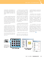
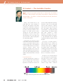
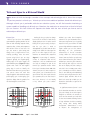
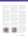
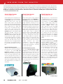
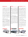
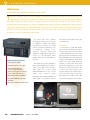
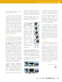
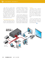


![Propagation des incertitudes et calcul de courbes [...]](http://vs1.manualzilla.com/store/data/006375930_1-4df43dcd546398da03ef06f078c055d8-150x150.png)