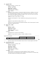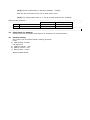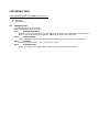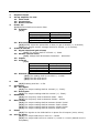
1
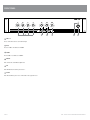
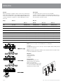
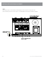
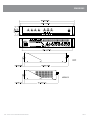
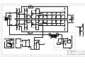
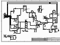
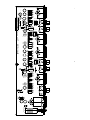
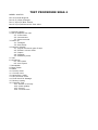
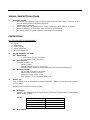
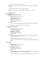
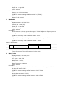
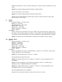
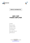
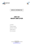
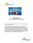
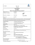
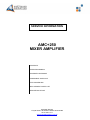
SERVICE INFORMATION
AMC+250
MIXER AMPLIFIER
CONTENTS:
OPERATION MANUAL
SCHEMATIC DIAGRAMS
COMPONENT OVERLAYS
TEST PROCEDURE
REPLACEMENT PARTS LIST
SERVICE BULLETINS
Australian Monitor
1 Clyde Street, Silverwater NSW 2128 Australia
+61 2 9647 1411
www.australianmonitor.com.au
AMC SERIES
+
30W/60W/120W/250W MIXER AMPLIFIERS
INSTALLATION AND OPERATION MANUAL
IMPORTANT SAFETY INFORMATION
1. Save the carton and packing material even if the equipment has
arrived in good condition. Should you ever need to ship the unit, use
only the original factory packing.
2. Read all documentation before operating your equipment. Retain
all documentation for future reference.
3. Follow all instructions printed on unit chassis for proper operation.
4. Do not spill water or other liquids into or on the unit, or operate
the unit while standing in liquid.
5. Make sure power outlets conform to the power requirements listed
on the back of the unit.
6.
Do not use the unit if the electrical power cord is frayed or broken.
The power supply cords should be routed so that they are not likely
to be walked on or pinched by items placed upon or against them,
paying particular attention to cords and plugs, convenience
receptacles, and the point where they exit from the appliance.
7. Always operate the unit with the AC ground wire connected to the
electrical system ground. Precautions should be taken so that the
means of grounding of a piece of equipment is not defeated.
8. Mains voltage must be correct and the same as that printed on the
rear of the unit. Damage caused by connection to improper AC voltage
is not covered by any warranty.
13.
Do not block fan intake or exhaust ports. Do not operate equipment
on a surface or in an environment which may impede the normal flow
of air around the unit, such as a bed, rug, weathersheet, carpet,
or completely enclosed rack. If the unit is used in an extremely dusty
or smoky environment, the unit should be periodically “blown free”
of foreign matter.
14. Do not remove the cover. Removing the cover will expose you
to potentially dangerous voltages. There are no user serviceable
parts inside.
15. Do not drive the inputs with a signal level greater than that required
to drive equipment to full output.
16. Do not connect the inputs / outputs of amplifiers or consoles to any
other voltage source, such as a battery, mains source, or power supply,
regardless of whether the amplifier or console is turned on or off.
17.
Do not run the output of any amplifier channel back into another
channel’s input. Do not parallel- or series-connect an amplifier output
with any other amplifier output. Australian Monitor Inc is not
responsible for damage to loudspeakers for any reason.
18. Do not ground any red (“hot”) terminal. Never connect a “hot” (red)
output to ground or to another “hot” (red) output!
19. Non-use periods. The power cord of equipment should be unplugged
from the outlet when left unused for a long period of time.
9. Have gain controls on amplifiers turned down during power-up
to prevent speaker damage if there are high signal levels at the inputs.
20. Service Information Equipment should be serviced by qualified service
personnel when:
10 Power down and disconnect units from mains voltage before making
connections.
A. The power supply cord or the plug has been damaged.
B. Objects have fallen, or liquid has been spilled into the equipment
C. The equipment has been exposed to rain
11. Never hold a power switch in the “ON” position if it won’t stay
there itself!
12. Do not use the unit near stoves, heat registers, radiators, or other heat
producing devices.
D. The equipment does not appear to operate normally, or exhibits a marked change in performance
E. The equipment has been dropped, or the enclosure damaged.
THIS SAFETY INFORMATION IS OF A GENERAL NATURE AND MAY BE SUPERSEDED BY INSTRUCTIONS CONTAINED WITHIN THIS MANUAL
INTRODUCTION AND CONTENTS
INTRODUCTION
3
FRONT PANEL
4
REAR PANEL
5
INSTALLATION
6
Master volume and overall treble and bass controls are provided, along with Vox
triggered muting (defeatable), giving channel 1 priority over inputs 2, 3 and 4.
There is also the facility to add a tone generator card.
TROUBLESHOOTING AND BLOCK DIAGRAM
7
FUNCTIONAL NOTES AND INTERNAL ADJUSTMENTS
8
The Australian Monitor AMC+ series gives the contractor a low cost alternative
in applications that are price sensitive, but still require a high quality of sound
reproduction and reliability.
DIMENSIONS
9
The Australian Monitor AMC+ series of amplifiers takes the heritage and
reliability of our famous AMIS series amplifiers and integrates these features
into low cost amplifiers for applications where reliability is everything, but the
more elaborate features of our AMIS series are not required.
Available in 30, 60, 120 and 250 watt versions, the AMC+ series are 2 RU mixer
amplifiers, featuring 70/100 volt line and 4 ohm outputs, and 4 universal
mic/line inputs.
SPECIFICATIONS
10 – 11
AUS, EUR, USA
Copyright 1st Apr 2005
Rev A: 1st Apr 2005
Rev B: 6th Jun 2006
Rev C: 26th May 2008
CAUTION
This symbol is intended to alert the user to the presence of uninsulated
“dangerous voltage” within the products enclosure that may be of sufficient
magnitude to constitute a risk of electric shock to persons.
RISK OF ELECTRIC SHOCK
DO NOT OPEN
CAUTION: TO REDUCE THE RISK OF ELECTRIC SHOCK,
DO NOT REMOVE COVER (OR BACK),
NO USER SERVICEABLE PARTS INSIDE,
REFER SERVICING TO QUALIFIED SERVICE PERSONAL.
This symbol is intended to alert the user to the presence of important
operational and maintenance (servicing) instructions in the literature
accompanying the appliance.
Caution:
WARNING!
To prevent electric shock do not use this (polarised) plug with an extension
cord, receptacle or other outlet unless the blades can be fully inserted to
prevent blade exposure. To prevent electric shock, match wide blade of
plug to wide slot, fully insert.
TO REDUCE THE RISK OF FIRE OR ELECTRIC SHOCK
DO NOT EXPOSE THIS EQUIPMENT TO RAIN OR MOISTURE.
AMC+ SERIES INSTALLATION AND OPERATION MANUAL
PAGE 3
front PANEL
1
2
3
4
5
6
1 CH 1–4
These control the levels for each channel input.
2 Bass
There is 12dB of cut and boost at 100Hz.
3 Treble
There is 9dB of cut and boost at 10kHz.
4 Master
This controls the overall mixed output level.
5 On
This LED indicates the unit is powered “on”.
6 Power
This switch switches power on or off the mains. The up position is on.
PAGE 4
AMC+ SERIES INSTALLATION AND OPERATION MANUAL
REAR PANEL
5
4
7
6
1 CH 1–4
Each channel input section has two inputs: XLR input – This
is a balanced microphone input. It has an input sensitivity of
1mV. RCA input – This is an unbalanced line level input. It
has an input sensitivity of 150mV. The two RCA sockets are
summed to mono internally.
3
2
Minimum Impedance
1
AMC+30 AMC+60 AMC+120
AMC+250
166ohm 333ohm 83ohm 166ohm 41ohm
83ohm
20ohm
40ohm
4ohm 4ohm 4ohm
4ohm
Distributed Line Output
70V (115V version) 100V (230/240V version) Low Impedance Output
2 REC Output
The REC output is on unbalanced RCA connectors. The output
level is 150mV into 10kohm at rated output. The output is
dual mono.
The REC output is not affected by the MASTER volume control
or the BASS and TREBLE controls.
The REC output does not receive the tone signal if the optional
tone generator module is installed.
(both versions)
Note: Only connect one output – either Distributed Line or Low Impedance per channel.
Do not connect LowZ and 70/100V at the same time.
The output strip comes fitted with a touch-proof cover held in place by two M3 machine screws
with flat and spring washers.
5 IEC Mains Input Socket
3 Line Output
The LINE output is on a balanced XLR connector. The output
level is 0.775V into 1k at rated output.
Note: When wiring the LINE output as unbalanced, Pin2
should be wired as hot and Pin1 should be wired as ground/
shield. Do not wire Pin3.
4 Direct Out
This is a standard IEC 3 pin socket. It accepts a standard IEC mains cable, provided. The fuse
draw at 5 contains the mains fuse and a spare. The mains fuse is a time lag (slow blow)
HRC 20mm x 5mm ceramic type fuse.
The ratings are:
AMC+30 AMC+60 AMC+120 AMC+250
230V/240V model
115V model 0.5A 1.6A 2A
2.15A
1A 3.15A 4A
6.3A
Always replace the fuse with one of the same value and type.
The speaker connections are on the 12 pole terminal strip.
There is a low impedance output (OHM) and a distributed line
voltage output (LINE). 70V out is available on 115V models.
100V out is available on 230V/240V models.
Note: Always disconnect power to the amplifier before replacing fuses.
6 (Optional) Tone Module
These terminals are for use with an optional tone module (not supplied). Use Australian Monitor
ATC5488 module.
7 Phantom Power
12V phantom power is available for condenser or electret microphones on the XLR input when
this switch is pushed in.
AMC+ SERIES INSTALLATION AND OPERATION MANUAL
PAGE 5
installation
Mounting
When rack mounting, it is advisable to allow 1 rack space above and below the
amplifier. When multiple amplifiers are mounted in a rack, exhaust fans should
be used on the rack. Airflow for cooling the AMC30, AMC60 and AMC120 is by
convection from bottom to top. Airflow for cooling the AMC250 is by fan from
front to side.
Direct Output
The output terminal strip accepts wire sizes from 16-22AWG
(1.5mm2 – 0.35mm2) or spade lugs. The following table should be used as a
guideline for cable sizes. Regulations in your area may require different gauged
wire and should be checked before using.
Output Wire Size
Distance
AMC 30 AMC+60 AMC+120 AMC+250
100V Up to 50m AWG26(0.12mm2)
AWG26(0.12mm2) AWG24(0.2mm2)
AWG22(0.35mm2)
50m–200m AWG24(0.2mm2) AWG20(0.5mm2) AWG18(0.75mm2)
AWG16(1.5mm2)
Over 200m AWG20(0.5mm2) AWG18(0.75mm2) AWG16(1.5mm2)
AWG13(2.5mm2)
70V Up to 50m AWG26(0.12mm2) AWG24(0.2mm2) AWG22(0.35mm2)
AWG18(0.75mm2)
50m–200m AWG20(0.5mm2) AWG18(0.75mm2) AWG16(1.5mm2)
AWG13(2.5mm2)
Over 200m AWG18(0.75mm2) AWG16(1.5mm2) AWG13(2.5mm2)
AWG10(6.0mm2)
4 ohm Up to 10m AWG18(0.75mm2) AWG18(0.75mm2) AWG18(0.75mm2)
AWG18(0.75mm2)
10m–30m AWG13(2.5mm2) AWG13(2.5mm2)
AWG13(2.5mm2)
AWG13(0.35mm2)
Over 30m Not Recommended Not Recommended Not Recommended
Not Recommended
+
Note: Only connect one output – either Distributed Line or Low Impedance.
Line Output
The LINE output XLR can be used to connect up to 6 booster amplifiers. Balanced wiring (shielded
pair cable) is recommended.
Note: When wiring the LINE output as unbalanced, Pin2 should be wired as hot and Pin1 should
be wired as ground/shield. Do not wire Pin3.
REC Output
The REC output wiring
should be kept as short
as possible.
Input Connections
For wiring balanced in, pin 2 is hot.
Unbalanced wiring on the microphone
inputs is not recommended.
Balanced input wiring (shielded pair cable)
is recommended. Unbalanced RCA wiring
should be keep as short as possible.
PAGE 6
AMC+ SERIES INSTALLATION AND OPERATION MANUAL
troubleshooting and block diagram
Troubleshooting Guide
Trouble
Likely Cause
Remedy
Power LED not on
Power not reaching amplifier
Check power switch is on
Check mains connection
Check mains fuse
Distorted sound
Output is short circuit
Check speaker loads for shorts
Input is overloaded
Reduce input level at source
Output is being over driven
Reduce volume levels on front panel
Bass control is turned up
Reduce Bass control level
Volume controls down
Check volume controls
Amplifier has overheated
(AMC+60, AMC+120 AMC+250 only)
Check for obstructions above and below
Make sure the amplifier is well ventilated
DC fuse(s) blown
Refer product to local Australian Monitor dealer
No sound from channels 2 and 3
Priority function is being used
Remove signal (disconnect input) from channel 1 OR
Disable priority function (see Internal Adjustments)
Tones do not sound when triggered
Tone generator module not installed
Purchase optional Tone generator module
No sound but amp is on
AMC+ SERIES INSTALLATION AND OPERATION MANUAL
PAGE 7
functional notes and internal adjustments
PRIORITY
Channel 1 will mute channels 2, 3 and 4. This will only occur when signal appears on channel 1, irrespective of the channel volume control.
Priority can be disabled. (See below). The release time is approx. 3 secs and is NOT adjustable. The mute depth is approx. 40dB and is not adjustable.
PAGE 8
AMC+ SERIES INSTALLATION AND OPERATION MANUAL
dimensions
AMC+ SERIES INSTALLATION AND OPERATION MANUAL
PAGE 9
specifications
AMC+ 30 AMC+ 60 AMC+ 120
AMC+ 250
30W 60W 120W
250W
> 75dBr > 75dBr > 80dBr
>85dBr
85Hz-15kHz 75Hz-15kHz 75Hz-15kHz
30Hz-20kHz
1.0A 0.5A 1.6A (x2) 3.15A 1.6A 4A 4A
2A
8A
6.3A
3.15A
10A (x2)
96% 93% 93%
90%
SIZE (WXHXD) 482 x 88 x 190mm 19” x 3.5” x 7.5” 482 x 88 x 281mm 19” x 3.5” x 11.1” 482 x 88 x 281mm
19” x 3.5” x 11.1”
482 x 88 x 384mm
19” x 3.5” 15.1”
NET WEIGHT 6.0kg 13.2lb 8.5kg 18.7lb 10.5kg
23.1lb
11.5kg
25.3lb
SHIPPING WEIGHT 7.5kg 16.5lb 10.5kg 23.1lb 12.5kg
27.6lb
14kg
30.8lb
510 x 145 x 297mm 20.1” x 5.7” x 11.7” 525 x 175 x 385mm 20.7” x 6.9” x 15.2” 525 x 175 x 385mm
20.7” x 6.9” x 15.2”
525 x 185 x 470mm
20.7” x 7.3” x 18.5”
MAINS CURRENT DRAW (240V)
FULL POWER 1/3 POWER 1/8 POWER IDLE 0.35A 0.23A 0.17A 0.08A 0.66A 0.44A 0.32A 0.13A 1.20A
0.80A
0.55A
0.15A
2.53A
1.61A
1.10
0.15A
MAINS CURRENT DRAW (115V)
FULL POWER 1/3 POWER 1/8 POWER IDLE 0.73A 0.48A 0.35A 0.17A 1.38A 0.92A 0.67A 0.27A 2.50A
1.67A
1.15A
0.31A
5.28A
3.36A
2.30A
0.31A
THERMAL OUTPUT (W)
FULL POWER 1/3 POWER 1/8 POWER IDLE 38W 33W 26W 11W 67W 63W 51W 19W 128W
118W
91W
26W
259W
231W
168W
26W
THERMAL OUTPUT (BTU/HR)
FULL POWER 1/3 POWER 1/8 POWER IDLE 130 113 90 38 229 215 172 65 437
403
311
89
884
788
573
89
POWER OUTPUT (0.5%THD, 1KHZ) S/N RATIO POWER BANDWIDTH (-3dB +1dB) FUSES MAINS (115V) MAINS (230/240V) DC OUTPUT REGULATION SHIPPING DIMENSIONS (WXHXD) *1/3 and 1/8 power levels relate to voltage changes, not load changes.
PAGE 10
AMC+ SERIES INSTALLATION AND OPERATION MANUAL
specifications
COMMON TO ALL MODELS
THD (1KHz, -1dB) Better than 0.5%
MIC INPUT SENSITIVITY IMPEDANCE HEADROOM 1mV @ 200ohm
1k3 ohm
77mV (37dB)
AUX INPUT SENSITIVITY IMPEDANCE HEADROOM 0.5V+/@100kohm
>200kohm
> 15V (>30dB)
TONE CONTROL BASS @ 100HZ TREBLE @ 10KHZ +/- 12 dB
+/- 9 dB
LINE OUT NOMINAL OUTPUT OUTPUT IMPEDANCE 0.775V @ 1kohm
100ohm
REC OUT NOMINAL OUTPUT OUTPUT IMPEDANCE 250mV @ 10kohm
1kohm
AMC+ SERIES INSTALLATION AND OPERATION MANUAL
PAGE 11
AUSTRALIA AND NEW ZEALAND
www.australianmonitor.com.au
SYDNEY
MELBOURNE
BRISBANE
ADELAIDE
PERTH
AUCKLAND
(NSW & ACT SALES)
(VIC & TAS SALES)
(QLD SALES)
(SA & NT SALES)
(WA SALES)
(NZ SALES)
1 Clyde Street
Silverwater
NSW 2128
Private Bag 149
Silverwater NSW 1811
Phone: (02) 9647 1411
Fax: (02) 9648 3698
Email:
[email protected]
22/277
Middleborough Road
Box Hill VIC 3128
PO Box 151 Blackburn
South VIC 3130
Phone: (03) 9890 7477
Fax: (03) 9890 7977
Email:
[email protected]
42 Commercial Road
Fortitude Valley
QLD 4006
PO Box 2578 Fortitude
Valley BC QLD 4006
Phone: (07) 3852 1312
Fax: (07) 3252 1237
Email:
[email protected]
31 Walsh Street
Thebarton
SA 5031
PO Box 157
Hindmarsh SA 5007
Phone: (08) 8352 4444
Fax: (08) 8352 4488
Email:
[email protected]
3/11 Howe Street
Osborne Park WA 6017
PO Box 1281
Osborne Park BC
WA 6916
Phone: (08) 9204 0200
Fax: (08) 9244 3783
Email:
[email protected]
9C Piermark Drive
Albany 0752
New Zealand
PO Box 300-512
Albany 0752
Phone: (09) 415 9426
Fax: (09) 415 9864
Email:
[email protected]
EUROPE / ASIA / MIDDLE EAST
www.australianmonitor.com.au
INTERNATIONAL SALES
1 Clyde Street Silverwater NSW 2128 Australia
Private Bag 149 Silverwater NSW 1811
Phone: + 61 2 9647 1411
Fax: + 61 2 9748 2537
Email: [email protected]
1
2
3
4
6
5
R44
10K
C9
Vc
NC
D
R3
22K
Dirven by balanced signal
R7
100E
R13
10K
D1
1N4007
*under PCB
BIAS
F1
D
8 AMP HRC
C7
C1
R1
1K5
T1
C1815
R21
1K
C3
4.7u/25
T3
BD139
470n/100V poly
C16
1n
THERMISTOR 10K
CN1
TH1
1
2
3
4
5
6
R17
100E
R4
330K
VCC
R11
1K
R8
2K2
BC639
C17
1n
C2
R2
1K5
R9
2K2
R29
47R
T6
BC639
Driver TXFR 1:1
R22
1K
T4
BD139
T2
C1815
T11
TIP35C
T13
TIP35C
T15
TIP35C
T16
TIP35C
TF1
.
R33
0.39E/5W
R35
0.39E/5W
R37
0.39E/5W
R39
0.39E/5W
R40
0.39E/5W
Com
R25
220E
R19
680R
C4
4.7u/25
R12
1K
R31
470R
R28
47R
R24
220E
R15
47K
T9
TIP35C
100V
68R
R18
680R
R14
47K
T7
TIP41C
R27
T5
TF2
CON6
C
NC
0E
24V
R5
330K
R23
*under PCB
RX1
R32
270R
470R
4Ohm
R34
0.39E/5W
R36
0.39E/5W
R38
0.39E/5W
R51
0.39E/5W
R59
0.39E/5W
Com
R30
R26
68R
0E
C8
24V
T8
TIP41C
T10
TIP35C
T12
TIP35C
T14
TIP35C
T18
TIP35C
T20
TIP35C
C
R41
680E
470n/100V poly
NC
R6
22K
R10
100E
R16
10K
R20
100E
D2
1N4007
*under PCB
BIAS
R42
10K
PR1
1k
Vc
R45
10K
C10
VC +24V
+24V
CN
NC
B
R43
1K
VC
CN2A
1
2
3
4
VC
24V
VC
R49
2
V+
V-
R40
2K2
C5A
6800u/63V
IC5B
1458
T16
BD139
C5B
6800u/63V
2
6
T19
BD 139
47K
3
5
7
24V
1K5
LM393
IC5A
1 R50
2k2
PRIM1
D7
4
3
L?
230V
BR1
KBPC15
8
1
AC
AC
10V
R46
R48
18K
4
L?
Mains 240 V
B
R52
68E / 2W
CN2B
R39
(150E/5W) X 2
2A HRC
T15
BC546B
CN
1
2
3
4
F2
BIAS
F1
8 AMP HRC
24V
C13
47/50
FAN
24V S1
R47
1K
C14
47/50
FAN CIRCUT
A
A
Australian Monitor
AMC+250
1
2
3
4
5
6
1
2
3
4
5
6
R44
10K
C9
Vc
NC
A
R3
22K
Dirven by balanced signal
R7
100E
R13
10K
D1
1N4007
*under PCB
BIAS
T1
C1815
R21
1K
C3
4.7u/25
470n/100V poly
C16
1n
THERMISTOR 10K
CN1
R4
330K
TH1
VCC
T3
BD139
R11
1K
R5
330K
C17
1n
C2
R23
NC
R8
2K2
BC639
R9
2K2
BC639
Driver TXFR 1:1
R22
1K
T2
C1815
T13
TIP35C
T15
TIP35C
T16
TIP35C
TF1
.
R33
0.39E/5W
R35
0.39E/5W
R37
0.39E/5W
R39
0.39E/5W
R40
0.39E/5W
70V
4Ohm
R29
39R
R32
470R
T6
T4
BD139
T11
TIP35C
Com
R25
220E
R19
680R
C4
4.7u/25
R12
1K
R31
470R
R28
33R
R24
220E
R15
47K
T9
TIP35C
100V
68R
R18
680R
R14
47K
T7
TIP41C
R27
T5
TF2
CON6
R2
1K5
A
0E
24V
B
F1
10AMP HRC
C7
C1
R1
1K5
1
2
3
4
5
6
R17
100E
R34
0.39E/5W
R36
0.39E/5W
R38
0.39E/5W
R51
0.39E/5W
R59
0.39E/5W
Com
R30
R26
68R
0E
C8
24V
T8
TIP41C
T10
TIP35C
T12
TIP35C
T14
TIP35C
T18
TIP35C
T20
TIP35C
470n/100V poly
R6
22K
R10
100E
R16
10K
R20
100E
NC
D2
1N4007
*under PCB
BIAS
VC
+24V
+24V
CN
NC
PR1
1k
C
CN2A
230V T4A 115V T8A HRC
R43
1K
VC
1
2
3
4
VC
24V
VC
R49
L1
PRIM1
V+
V-
BR1
KBPC5010
R40
2K2
C5A
6800u/63V
6800u/63V
24V
47/50
LM393
FAN
24V S1
R47
1K
C14
47/50
T19
BD 139
1 R50
2k2
2
IC5A
C13
1K5
47K
3
5
6
24V
D7
115V
IC5B
1458
7
T16
BD139
C5B
4
SW-DPDT
3
AC
AC
115V
R46
R48
18K
8
1
2
L2
230V 115VAC
4
125C
C
R52
68E / 2W
CN2B
R39
(150E/5W) X 2
F2
T15
BC546B
CN
1
2
3
4
S1
R42
10K
Vc
C10
F2
BIAS
F1
10AMP HRC
R45
10K
B
R41
680E
FAN CIRCUT
D
D
Title
AMC 250 AMP -02
Size
Number
Revision
B
Date:
File:
1
2
3
4
5
4/23/2012
\\..\AMC250 250P.SCH
Sheet of
Drawn By:
6
1 of 1
DERICK
1
2
3
4
5
6
7
100R
8
R46
R47
100R
R7
180k
VCC
A
A
C3
10pF
R23
10K
IC1A
LM833
C1
4u7
2
1
T5
C1815
TAPE OUT
4
3
R1
4k7
C8
VR1
50k
33n
1/2VCC
R24
10K
C19
47/25V
C13
100P
R41
2K2
R18
10k
1/2VCC
C7
4u7
R10
10k
R12
10k
VR4
50k
VCC
CN1
6
GND 1/2VCC
VCC
OUT+
7
IN+
5
C4
IC3B
LM833
C9
1200P
4.7u
R11
6k8
R6
VR5
50k
VR2
50k
T1
C1815
C10
47PF
VCC
PRIORITY
6
1
2
3
2k2
R2
2k2
1
2
3
4
5
6
7
VCC
VCC
T4
C15
47pf
T3
C1815
R30
6
5
2k2
VCC
R36
T6
C1815
10K
VR6
50k
R15
4k7
IC3A
LM833
2
1
4k7
3
T2
C1815
R40
10k
1/2VCC
VCC
C20
470/25
R26
6k8
R29
100E
2
TH+
1
TO AMP
3
10K
C16
47/25
C
R28
22K
IC4A
LM358
D3
3.9v
R21
R22
100K
IC4B
LM358
VR7
50k
C11
4u7
R33
3.9v
D1
BAV21
R9
2k2
10/25
D2
7
4.7U
R39
2k2
R4
100k
VCC
R19
4k7
C14
R14
BC556
2K2
R20
1M
C
4u7
R16
12K
R38
10k
8
2k2
10k
C17
D6
BAV21
VR3
50k
C12
100p
C2
R5
7
IC1B
LM833
1/2VCC
R3
2k2
B
1/2VCC
Tone Module Input
5
R8
OUT-
Signal
4
TAPE OUT
R13
6k8
IN-
VCC
X2
4
+12V
CH1
CH2
CH3
CH4
Line OUT+
Line OUT-
8
B
1
2
3
4
5
6
7
8
9
10
Signal
8
R17
10k
R34
10k
R27
220E
R37
10k
1K
TH-
R25
TO AMP
10K
CN2
D
1
2
3
4
5
6
IN+
INTHTH+
R32
R31
1K5
VCC
D
220E/2W
C21
1000/25
CN3
LED1
G Changed gain R16 22k->12k, C12 220p->100p, R19 1k->4k7
REV
REVISION NOTE:
A
B
C
D
E
F Changed to 4 channels
D4
12V1W
1
2
3
4
5
CKW
DRN
CKW
6
22/05/08
DATE
15/02/08
A8675$/,$1021,725
DRAWING No:
SIL/16/0345
DESCRIPTION:
AMC Mixer
DRAWN BY:
DATE: 2009-5-5
7
SHEET 1
8
of 1
1
2
3
4
5
RCA3
RCA 2P
6
7
8
R20
1K
TAPE OUT
RCA1A
RCA-4POLE
L
R21
1K
R2
330K
R6
4k7
A
R
R3
330K
C8
10/25 NP
R4
680R
C9
10/25 NP
R19
10R
C2
470p
CN1
6
R1
680R
C7
10/25 NP
R29
4k7
IC1B
LM833
C11
.1u
R5
4k7
C1
R28
4k7
7
5
GRD
AG(1/2 VCC)
+VCC
CH 1 OUT
CH 2 OUT
CH 3 OUT
CH 4 OUT
MIX OUT
MIX OUT
TAPE OUT
1
2
3
4
5
6
7
8
9
10
C10
4u7
8
XLR1
3
2
1
A
VCC
VCC
G
XLR-FEMALE
C25
4u7
470p
CON10
RCA1B
RCA-4POLE
L
R7
330K
XLR5
C13
10/25 NP
R8
330K
R
G
B
C21
4u7
R9
4k7
R11
680R
XLR2
3
2
1
XLR-FEMALE
C14
10/25 NP
C15
10/25 NP
C3
B
C12
4u7
VCC
1
IC1A
LM833
C24
10/25
R10
4k7
470p
VCC
R18
4k7
R15
330K
R
C17
10/25 NP
R20
10R
G
R16
680R
C18
10/25 NP
R13
680R
C16
10/25 NP
C6
470p
C19
4u7
8
6
XLR3
3
2
1
XLR-FEMALE
7
C5
R33
4k7
.1u
R17
4k7
470p
R26
4k7
R
R23
330K
C26
10/25 NP
R24
680R
C27
10/25 NP
R25
680R
C28
10/25 NP
G
C30
470p
C31
4u7
8
6
XLR4
3
2
1
XLR-FEMALE
7
5
IC2B
LM833
D
C29
R35
4k7
R34
4k7
1
C32
4.7u
VCC
2
SW1A
P/P
4
D
R27
4k7
470p
3
3
C20
R22
330K
RCA2B
RCA-4POLE
L
2
C
5
IC2B
LM833
R32
4k7
1
C23
10/25
R14
330K
RCA2A
RCA-4POLE
L
C
1/2VCC
3
4
R31
4k7
LINE OUT
470p
C4
R30
4k7
XLR-MALE
C22
4u7
2
R12
680R
3
2
1
REV
A
B
C
D
E
F
REVISION NOTE:
DRN
Added 4th channel & P/P
CKW
AU675$/,$1021,725
DATE
14/02/08
DRAWING No:
SIL/16/0339
DESCRIPTION:
AMC 120/60/30 MIC INPUT
DRAWN BY:
DATE: 2009-5-5
5
6
7
SHEET 1
8
of 1
R
R34
A23
T10
R36
T12
R38
J8
T14
T15
J9
A170_1
A29_1
J10
J11 J6
R28
TH1
T5
D7
R27
J15
+24V
A24
R29
A22
T13
R37
J7
J13 R42 R41
R43
R30
R8
A20
R35
J12
IN+
INR1
GND
TH+ R2
T11
J
R4
A21
R33
T6
R10
J3
R9
J16
T16
C13
C14
VCC
J5
CN1
J17
+24V
J2
R7
T9
T7
R31 R21 R24
PR1
C1
R6
J18
J14
R40
CN2A
F2
R51
T15
F1
T18
R39
C5A
AMC+250 AMP
T16
R53
R39
A170
A29
T20
R40
A25
A26
A27
A28
C5B
O/P PRIMARY
QC1
O/P PRIMARY
QC2
BRIDGE +VE
OP CT1
BRIDGE GND
QC6
QC3
QC4
QC5
OP CT2
C3
R44
C7
D1 R23
R20
A17
D2
R11
R12
J1
R22 R26
R15
R16
T8
R25
R32
R14
R13
C8
T1
C16
C2
GND
T1
T2
TH+
C4
C17
C9
GND
R5
R45
C10
T3
T4
R19
C15
R17
R18
R3
J12
GND
R1
1/2 VCC
R6
VCC
CH1
R8
CH2
CH3
R14
T6
J18
T1
OUT-
TAPE OUT
CN1
R30
R19
C1
T3
D2 R21
C16
EN
OFF
PRIORITY
R46
C15
R3
R37
R36
IC4
J6
R25
J1
R28
SIGR27
R9
R26
SIG+
VR3
TH+
C21
GND
D4
X2
J9
R31
CN2
J10
+VCC
T4
NC
R38
R39
MUTE
VR7
GND
R40
TONE OUT
C4
R32
J13
C20
C19
C2
R7
J10
C3
J15
2K2
C7
VR4
R41
C10
IC1
C8
R47
R4
R22
D1 R20 D6
VR2
J17
J16
0R
J19
R2
R23
VR1
T5
OUT+
C14
J7
J7
GND
+M
+VCC
R5
J14
J8
R12
VR5
D3
R34
R10
J2
C9
R13
R29
R11
R16
R17
C12
R15
T2
C11
R33
J5
VR6
IC3
J3
C13
J4
J3
K
A
R18 CN3
C17
R24
R5
R6
C2
C10
IC1
C11
R19
C12
R7
R9
C4
TAPE OUT
R10
+
C14
R11
R14
R15
C17
R32 R33
R16
RCA2
C5
+
C18
R17
R18
C19
C6
J4
IC2
C20
J3
XLR5
R21
C31
R23
C30
C26
R26
C29
R27
+
C27
R24
RCA3
R25
C28
+
XLR3
R13
C16
R12
C15
R20
+
XLR2
R8
C3
C13
+
C25
R35 R34
R21 R22
+
+
C1
C9
+
J1
J2
+
AMC+ input-E
+
R28 R29
+
+
C24
+
R4
CN1
+
R3
+
A59
XLR1
R2
C8
C23
+
+VE
CH1
CH2
CH3
CH4
OUTOUT+
R1
C7
+
R31 R30
+
GND
+
1/2 VCC
C21
C22
XLR4
C32
Phantom Power
S1
J6
J5
TEST PROCEDURE 5062-1
MODEL: AMC250
Rev
Rev
Rev
Rev
A 6/10/06 Original
B 11/10/06 Changes
C 30/11/07 New format
D 27/11/08 Correct AC fuse value
Outline
1. Physical checks
2. Set up amplifier for test
2.1. Fuse check
2.2. Connections
2.3. Reset controls
3. Power up
3.1. Voltages
3.2. Bias setup
4. Initial AC Checks
4.1. Signal check and gain of amp
4.2. Emitter current check
4.3. Inputs
4.4. Outputs
4.5. Phantom power
5. THD
6. Sensitivity
6.1. Mic inputs
6.2. AUX inputs
7. Bandwidth
8. Bass/Treble
9. Phase
10. Priority check
11. Current Limit
12. Noise floor / SNR
13. Fan/Thermal check
14. Final check for damage
15. Factory setting
16. Listening Test
16.1. Switch on thump
16.2. Audio quality
16.3. Priority
16.4. Current Limit
Test Procedure
VISUAL INSPECTION STAGE
1.
Physical checks
•
All screws for tightness (esp. bridge rectifier and transistor bolts), referring to the
torque setting of the manufacturing tools
•
Capacitors for polarity
•
Earth connection for good contact, using multimeter (XLR GND to AC earth)
•
Power transistors for shorts to heat sink using a multimeter
•
All wiring points for good contacts (soldering and crimping)
PRETESTING
PRE TESTING SETUP REQUIREMENT
a) Oscilloscope
b) Variac
c) Multimeter
d) Load [4ohm]
e) Signal generator
f) Phantom power jig
2.
Set up amplifier for test :
2.1. Fuse check
2 x AC fuses (3.15A), 20x5mm
2 x DC fuses (10A), 20x5mm
2.2. Connections
Connect amplifier to:
Variac (0Vac)
Signal generator (mic1, no signal)
Resistive load (4ohm on 4ohm terminal) with meters/oscilloscope
2.3. Reset controls:
All volume controls to minimum
Bass/treble control to centre
Phantom power switch to off
PR1 (preset) on the amplifier PCB CCW
3.
Power up :
Turn on power switch and adjust voltage to 230VAC. Watch current meter for excess
current draw.
(P/F) Current shall not exceed 0.5Aac.
3.1. Voltages
Measure the following DC voltages with a multimeter referenced to mains safety
earth or the chassis.
(P/F)
DC power supply
Input PCB rail (ICp8)
Input PCB ½rail (ICp1)
Input PCB gnd (ICp4)
3.2. Bias setup
Pass Range
47.5VDC - 50.5VDC
11.0.0VDC – 13.0VDC
5.0VDC – 6.0VDC
-0.1VDC – +0.1VDC
Put a multimeter across an emitter resistor.
(P/F) Slowly adjust the preset PR1 so that you get 4.5mVDC (+/-0.5mVDC)
reading.
Check Quiescent Voltage across all Emitter resistors.
(P/F) The emitter resistor voltages shall be 4.5mVDC (+/-2.0mVDC).
[Setup for next test]
4.
Initial AC Checks :
4.1. Signal check and gain of amp
Setup
Signal generator = 1mVAC, 1kHz
Signal in = Ch1 XLR
All channel pots = min (CCW)
Bass/Treble = centre
Master pot = max (CW)
Output metering = 4ohm out
Load = 4ohm
Procedure
Turn up Ch1 volume control to full. Watch for irregularities with output.
(P/F) Output voltage shall be 31.6VAC +/-2VAC.
4.2. Emitter current check
Setup
Signal generator = 1mVAC, 1kHz
Ch1 pot = max (CW)
Ch2-4 pot = min (CCW)
Bass/Treble = centre
Master pot = max (CCW)
Output metering = 4ohm out
Load = 4ohm
Procedure
Set output to 22VAC using master volume control. Check voltage across
emitter resistors of power devices.
(P/F) Voltage shall be between 300mVDC – 400mVDC.
[Setup for next test] Reset Ch1 volume pot to min. Set master volume to
max.
4.3. Inputs
Setup
Signal generator = 1mVAC, 1kHz
Signal in = Ch1 XLR
All channel pots = min (CCW)
Bass/Treble = centre
Master pot = max (CW)
Output metering = 4ohm out
Load = 4ohm
Procedure
Check the output for all XLR input channels. Watch for irregularities with
output while turning up each channel volume pot.
[Setup for next test] Set the signal generator to give 31.6V on output.
4.4. Outputs
Setup
Signal generator = ~1mVAC adjusted for 31.6V out with pots max, 1kHz
Signal in = Ch4 XLR
Channel pots = max (CW)
Bass/Treble = centre
Master pot = max (CW)
Output metering = 4ohm out
Load = 4ohm
Procedure
Using a multimeter check the following:
(P/F)
Pass Range
100V line
90VAC – 110VAC
Tape output – left
200mVAC – 300mVAC
Tape output – right
200mVAC – 300mVAC
Line output
0.65VAC – 0.80VAC
Measure on the terminal block, RCA connector both left and right and XLR
connector between pins 2 and 3.
[Setup for next test] Remove input signal.
4.5. Phantom power
Setup
Signal in = none
Channel pot = max (CW)
Bass/Treble = centre
Master pot = max (CW)
Output metering = 4ohm output terminals
Load = 4ohm
Procedure
Set phantom switch to on. Measure the DC voltage on Ch1 XLR input pins 2
and 3 ref to pin 1.
(P/F) The reading shall be 12.0VDC +/-1.0VDC.
Using the phantom power LED jig connect to XLR in.
Set the phantom power switch to off
(P/F) The LED shall be off.
Switch the phantom power on.
(P/F) The LED shall be on.
Repeat for each channel.
[Setup for next test] Connect signal to Ch1 XLR.
Remove all inputs and connections. Attach tested tag. Turn all volume pots to min.
FINAL TESTING
REQUIREMENTS FOR FINAL TESTING:
a) Neutrik
b) Load 40ohm
c) Multimeter
d) Oscilloscope
e) Microphone
f) Variac
5.
THD
Setup
Signal generator = 1mVAC, 1kHz
Signal in = Ch1 XLR
Channel pot = min (CCW)
Bass/Treble = centre
Master pot = min (CW)
Output metering = 100Vout
Load = 40ohm
Procedure
Set master pot to max. Turn up Ch1 pot to 70VAC (+/-1.0VAC) on output. Measure
THD.
(P/F) Reading shall be < 0.5%.
Values to be recorded:
Value
5.
6.
THD
Pass Range
0% – 0.5%
Sensitivity
6.1. Mic inputs
Setup
Signal generator = 1mVAC, 1kHz
Signal in = Ch1 XLR
Ch1 pot = somewhere
Ch2-4 pots = min (CCW)
Bass/Treble = centre
Master pot = max (CW)
Output metering = 100Vout
Load = 40ohm
Procedure
Set channel pot to max.
(P/F) The output reading shall be 100VAC (+/- 5VAC).
Repeat for all channels.
[Setup for next test] Move the signal in back to channel 1 RCA. Set the signal
generator to 0.5VAC
6.2. AUX inputs
Setup
Signal generator = 0.5VAC, 1kHz
Signal in = Ch1 RCA
Channel pot = max (CW)
Bass/Treble = centre
Master pot = max (CW)
Output metering = 100Vout
Load = 40ohm
Procedure
Measure the 100V line output.
(P/F) The output readings shall be 100VAC (+/- 5VAC).
Repeat for all channels.
7.
Bandwidth
Setup
Signal generator = 0.5VAC, 1kHz
Signal in = Ch4 RCA
Channel pot = max (CW)
Bass/Treble = centre
Master pot = max (CW)
Output metering = 100Vout
Load = 40ohm
Procedure
Set the channel 4 volume pot so the output is 70VAC. Adjust the frequency on the
signal generator down till the output is 50VAC.
(P/F) The frequency shall be between 20Hz – 30Hz.
Adjust the frequency on the signal generator up till the output is 50VAC.
(P/F) The frequency shall be between 20kHz – 40kHz.
Values to be recorded
Value
7a.
7b.
Bandwidth - low
Bandwidth - high
Pass Range
20Hz - 30Hz
20kHz - 40kHz
[Setup for next test] Set the frequency back to 1kHz.
8.
Bass/Treble
Setup
Signal generator = 0.5VAC, 1kHz
Signal in = Ch4 RCA
Ch1-3 pot = max (CW)
Ch4 pot = somewhere
Bass/Treble = centre
Master pot = max (CW)
Output metering = 100Vout
Load = 40ohm
Procedure
Set the frequency to 100Hz. Set the channel 4 volume so the output is 15VAC. Set
the bass pot to max (CW).
(P/F) The output reading shall be between 60VAC-70VAC.
Set the bass pot to min (CCW).
(P/F) The output reading shall be between 3VAC-4.5VAC.
Reset the bass pot to centre. Set the frequency to 10kHz. Set the treble pot to max
(CW).
(P/F) The output reading shall be between 42VAC-50VAC.
Set the treble pot to min (CCW).
(P/F) The output reading shall be between 4VAC-6VAC.
[Setup for next test] Reset the treble pot to centre. Reset Ch4 pot to max (CW).
Move signal in to Ch1 RCA.
9.
Phase
Setup
Signal generator = 0.5VAC, 1kHz
Signal in = Ch1 RCA
All channel pots = max (CW)
Bass/Treble = centre
Master pot = max (CW)
Output metering = 100Vout
Load = 40ohm
Procedure
Attach channel 2 of the CRO to the input. Make sure the CRO is being triggered by
the input. Look at each output on channel 1 of the CRO. The CRO ground should be
connected to the common both for the low impedance outputs and the line outputs.
(P/F) The signals on the CRO shall be in phase for all outputs (100V, 4ohm).
10.
Priority check
Setup
Signal generator = 0.5VAC, 1kHz
Signal in = Ch4 RCA
Ch pots = max (CW)
Bass/Treble = centre
Master pot = max (CW)
Output metering = 100Vout
Load = 40ohm
Procedure
Plug a microphone into input 1 and oscillator to input 4. Turn channel 1 pot to min
(CCW). Speak into the microphone.
(P/F) The output shall drop in level to < 10VAC.
Stop speaking and disconnect mic.
(P/F) The output shall return to 100VAC +/-10VAC in <10sec (Mental count is
acceptable).
Speak into the microphone. The output shall drop in level to < 10VAC. Keep
speaking. Set the Disable/Enable link to disable.
(P/F) The output shall return to 100VAC +/-10VAC in <10sec (Mental count is
acceptable) while you are still speaking.
Insert Disable/Enable link to ENABLE.
[Setup for next test] Set master to min (CCW). Set ch1 to max.
11.
Current Limit
Setup
Signal generator = 0.5VAC, 1kHz
Signal in = Ch4 RCA
Ch pots = max (CW)
Bass/Treble = centre
Master pot = min (CCW)
Output metering = 100Vout
Load = 40ohm
Procedure
Change the load to 20ohms. Increase the signal such that at ~65VAC you can see
the overload protection coming on with a rounding of the sine wave. If it is there
then reduce the voltage to 30VAC out. Switch off the unit and connect a shorting
link to the 100V output. Switch the unit on.
(P/F) The mains current shall be < 3.5Aac.
Leave the unit shorted for ~10sec. Release the shorting link and check for the
output.
(P/F) The output shall be reading 30VAC +/-1V.
[Setup for next test] Change the load back to 80ohm. Set all volume pots to centre.
Remove the signal from Ch4.
12.
Noise floor / SNR
Setup
Signal in = none
Ch pots = centre
Bass/Treble = centre
Master pot = centre
Output metering = 100Vout
Load = 40ohm
Procedure
Put dummy lid on. Check for Hum & Noise.
(P/F) The output shall be reading < 6mVAC (-85dBr ref 100V).
Values to be recorded
Value
12.
Noise floor
Pass Range
0mV – 6mV
Set Ch1 volume to max. Set master volume to max. Connect signal to Ch1 RCA.
13.
Fan/Thermal check
Setup
Signal generator = 0.5VAC, 1kHz
Signal in = Ch1 RCA
Ch1 pot = max (CW)
Ch2-4 pot = centre
Bass/Treble = centre
Master pot = max (CW)
Output metering = 100Vout
Load = 40ohm
Procedure
Adjust channel 1 volume pot to an output reading of 70VAC. Connect a
thermometer to the temperature sensor. Wait the unit to heat up. A heat gun may
be used to speed up the heating of the heatsink.
(P/F) the fan shall switch on between 50degC - 70degC.
Stall the fan and wait for the unit to heat some more.
(P/F) The output shall mute to < 10V at a temp between 90–105degC
Values to be recorded
Value
13a.
13b.
14.
15.
Fan turn on
Thermal cutout
Pass Range
50degC – 70degC
90degC – 105degC
Final check for damage
Disconnect from test bench and inspect for scratches on external paint.
Factory setting
Set up the unit for default factory setting as below:
Links:
a) VOX Muting : Enable
Pot positions:
a) Channel volume : min
b) Master volume : min
c) Bass/Treble : centre
Attach tested sticker.
LISTENING TEST
REQUIREMENTS FOR LISTENING TEST SETUP:
a) CD Player
b) Speaker
c) Microphone
16.
Listening Test
Connect amplifier to the setup
Keep all pots full, tone at center.
16.1.
Switch on thump
Switch on the set and check for any ON Thump. Ensure unit does not thump. Check
that no low frequencies are audible. Make all channel pots minimum.
16.2.
Audio quality
Check CD Player (AUX) output for all channels and tone control for all channels.
16.3.
Priority
Check Priority function : CH 1 over CH 2, 3 & 4
16.4.
Current Limit
Short the output with signal ON. Signal should mute and return back.
Pass/Fail Summary
1.
2.
3.
Physical checks
Set up amplifier for test :
2.1. Fuse check
2.2. Connections
2.3. Reset controls:
Power up :
(P/F) Current shall not exceed 0.5Aac.
3.1. Voltages
(P/F)
DC power supply
Input PCB rail (p8)
Input PCB ½ rail (p1)
Input PCB ground (p4)
4.
5.
6.
7.
8.
9.
10.
Pass Range
47.5VDC - 50.5VDC
11.0VDC – 13.0VDC
5.0VDC – 6.0VDC
-0.1VDC – 0.1VDC
3.2. Bias setup
(P/F) Slowly adjust the preset PR1 so that you get 4.5mVDC (+/-0.5mVDC)
(P/F) The emitter resistor voltages shall be 4.5mVDC (+/-2.0mVDC).
Initial AC Checks :
4.1. Signal check and gain of amp
(P/F) The output shall be 15.5VAC +/- 2VAC.
4.2. Emitter current check
(P/F) Voltage shall be between 300mVDC – 400mVDC.
4.3. Inputs
4.4. Outputs
(P/F)
Pass Range
100V line
90VAC – 110VAC
Tape output – left
200mVAC – 300mVAC
Tape output – right
200mVAC – 300mVAC
Line output
0.65VAC – 0.80VAC
4.5. Phantom power
(P/F) The reading shall be 12.0VDC +/-1.0VDC.
(P/F) The LED shall be off.
(P/F) The LED shall be on.
THD
(P/F) Reading shall be < 0.5%.
Sensitivity
6.1. Mic inputs
(P/F) The output reading shall be 100VAC (+/- 5VAC).
6.2. AUX inputs
(P/F) The output readings shall be 100VAC (+/- 5VAC).
Bandwidth
(P/F) The frequency shall be between 20Hz – 30Hz.
(P/F) The frequency shall be between 20kHz – 40kHz.
Bass/Treble
(P/F) The output reading shall be between 60VAC-70VAC.
(P/F) The output reading shall be between 3VAC-4.5VAC.
(P/F) The output reading shall be between 42VAC-50VAC.
(P/F) The output reading shall be between 4VAC-6VAC.
Phase
(P/F) The signals on the CRO shall be in phase for all outputs (100V, 4ohm).
Priority check
(P/F) The output shall drop in level to < 10VAC.
(P/F) The output shall return to 100VAC +/-10VAC in <10sec (Mental count is
acceptable).
11.
12.
13.
(P/F) The output shall return to 100VAC +/-10VAC in <10sec (Mental count is
acceptable) while you are still speaking.
Current Limit
(P/F) The mains current shall be < 3.5Aac.
(P/F) The output shall be reading 30VAC +/-1V.
Noise floor / SNR
(P/F) The output shall be reading < 6mVAC (-85dBr ref 100V).
Fan/Thermal check
(P/F) the fan shall switch on between 50degC - 70degC.
(P/F) The output shall mute to < 10V at a temp between 90–105degC
AMC+ Parts
Circuit boards
Part Number
Factory code
Input board
Mixer board
AMC+30 output board
AMC+60 output board
AMC120+ mixer board
AMC+120 output board
AMC+250 output board
AMC+IB
AMC+120MB
AMC+30OPB
AMC+60OPB
AMC+120MB
AMC+120OPB
AMC+250OPB
B06044
B03048
B06047
B06044
B012046
BR025001
AMC+30TX
AMC+30OT
AMC+60TX
AMC+60OT
AMC+120PTX
BR0120036
AMC+120OT
AMC+250TX
AMC+250OT
BR0120036
BR030123
BR030124
BD6041
BD060127
BD0642
BR0120036
BR0120125
BR0250140
BR0250141
BR0120036
Transformers
AMC+30 mains transformer
AMC+30 output transformer
AMC+60 mains transformer
AMC+60 output transformer
AMC+120 mains transformer
AMC+120 drive transformer
AMC+120 output transformer
AMC+250 mains transformer
AMC+250 output transformer
AMC+250 drive transformer
Australian Monitor Service Bulletin
AMC+250 Mixer Amplifier
AMC+250P Booster Amplifier
11 May 2011
Outline
The AMC+250 mixer amplifier and AMC+250P booster amplifier have experienced a higher than acceptable
incidences of mains fuse failures at turn on.
Known Issue
Mains fuse failure.
Details
The cause of the issue has been identified as the mains fuse used in production being of a rating that is too low
for use in areas that encounter elevated mains voltages.
Solution
The problem can easily be rectified by placing the existing mains fuse as follows:
115V Operation:
T8A 250V slow-blow ceramic HRC type M205 fuse (20 x 5mm).
230V Operation:
T4A 250V slow-blow ceramic HRC type M205 fuse (20 x 5mm).
Procedure
1.
Remove the mains lead from the amplifier.
2.
Remove the fuse holder drawer that is part of the IEC mains input socket.
3.
Remove the two existing fuses (one of these is a spare fuse).
4.
Install two M205 size fuses as per the operating voltage above.
5. Reinstall the drawer.
Page 1 of 1
Australian Monitor Service Bulletin
AMC+ Mixer and Booster Amplifiers
Mains Fuses
20 February 2012
Applicable Models
This bulletin applies to AMC+30, AMC+60, AMC+120 and AMC+250 Mixer Amplifiers and the AMC+120P,
AMC+1202P and AMC+250P Booster Amplifiers manufactured prior to 2012.
Known Issue
The AMC+ range of mixer amplifiers and AMC+ booster amplifier have experienced a higher than acceptable
incidences of mains fuse failures at turn on.
Details
AMC+ products manufactured prior to 2012 are fitted with inferior Chinese fuses.
Solution
The problem can easily be rectified by placing the existing mains fuse with name brand quality fuses available
from Element14 as follows:
115V Operation
(North America)
Model
230V Operation
(Australia/Europe)
Fuse Rating
Element14
Fuse Rating
Element 14
AMC+30
T1A
1123115
T500mA
1123121
AMC+60
T3.15A
1123119
T1.6A
1123113
T4A
1123120
T2A
1123118
T8A
1123125
T4A
1123120
AMC+120
AMC+120P
AMC+250
AMC+250P
AMC+1202P
All fuses are Cooper Bussman 250VAC rated, slow-blow ceramic HRC type M205 cartridge.
All future production models will be fitted with these fuses.
Procedure
1.
Remove the mains lead from the amplifier.
2.
Remove the fuse holder drawer that is part of the IEC mains input socket.
3.
Remove the two existing fuses (one of these is a spare fuse).
4.
Install two M205 size fuses as per the operating voltage above.
5. Reinstall the drawer.
Page 1 of 1
Australian Monitor Service Bulletin
AMC+250 Mixer Amplifier
AMC+250P Booster Amplifier
9 March 2012
Applicable Models
This bulletin applies to AMC+250 and AMC+250P models manufactured prior to March 2012.
For Information Only
This bulletin is intended for service technicians only and is to be applied when replacing failed bridge rectifiers.
This bulletin does not apply to functional units.
Known Issue
A small number of bridge rectifier failures at power on have been observed.
Details
It is believed that RoHS compliant 35A bridge rectifiers are not as reliable as the earlier non-RoHS equivalents.
We have decided to increase the rating from 35A to 50A to provide additional headroom under turn on conditions.
Solution
When replacing a failed bridge rectifier (BR1), substitute the original 35A bridge with a 50A model as indicated in
the table below.
Model
VRRM
I(AV)
Terminals
Original Part
KBPC3510
1000V
35A
0.25" FASTON terminals
Replacement Part
KBPC5010
1000V
50A
0.25" FASTON terminals
Notes
All models manufactured March 2012 or later are fitted with the 50A replacement part.
Page 1 of 1