1
The TAP System
OEM & DIY Technical Information
This section of the manual describes the choices, features and wiring of the TAP series of modules and
boards. It is intended to serve as a wiring guide for OEM or DIY users who are building their own systems using
the TAP Modules. There is enough similarity to the TAP-X functions that it is suggested you review the TAP-X
instruction Manual to get an idea of the general operation of the TAP set of boards before diving into planning
and wiring a TAP DIY/OEM system.
Note:
Most of the boards we make are available for OEM/DIY use – except for two of the TAP-X Pre-amp
boards. The power supply board and the input select board from the TAP-X pre-amp are exclusive to it's design.
Features like the handling of the sub output and the power supply design are very specific parts of the system. It
is expected that users of the TAP boards will have their own buffer and power supply design ideas and so the
TAP OEM/DIY power and Input boards are designed with that in mind.
These documents are meant to be a guide for experienced builders – not a step-by-step set of DIY
assembly instructions. There are just too many different ways to assemble and use this set of parts to make stepby-step assembly instructions practical.........
The TAP Series of modules and boards includes the following:
Display Boards:
–
–
The full width Display Board as used in the TAP-X pre-amp.
The PRM-1 (A much smaller single digit Display Board with or without it's metal casing).
Power Supply Options:
–
–
–
DC Input Back Panel Mount Power Board (as used in the one input TAP-X Pre-amp)
Internal Power Board (Used with the PRM-1 front panel board or when using internal DC power)
Goldpoint BSA-1 Used as the system Power Supply.
Volume Control (Attenuator) Boards:
–
–
–
Slagleformer Modules (as used in the TAP-X pre-amp)
Hybrid resistor based Boards (10K or 50K Impedance)
Goldpoint BSA-1 Boards – a 2 channel binary attenuator
Input Select Boards:
–
Stereo Back Panel Board (6 RCA Inputs + Tape Out + Dual RCA outputs)
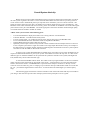
Overall System Hook-Up
Before diving into each board and module's hook-up instructions and functions I'll describe a bit about
the TAP system in general. The TAP is a series of boards and modules form the 'shell' of a pre-amp system or
can be used to create a full featured passive pre-amp that can be installed in your own custom casework. The
boards all connect from one to the other via standard 10 pin ribbon cables forming a power and data bus – The
BentBus. These cables send data and control circuitry power from module to module but none of the audio signal
path connections are part of the BentBus. The audio signal path connections should be made with high quality
wire hardwired from module to module as needed.
A Basic TAP system consists of the following parts:
–
–
–
–
–
–
A Front Panel Board for display and remote receive along with user activated buttons
A Remote Handset – included with all TAP systems
A Power supply board – To regulate the system power and get that power to the BentBus cable
Level Control Boards (Resistor Attenuator boards or Slagleformer Modules)
Optional Back Panel Input select boards may be used.
Optionally a Fiber Optic connection may be used to allow modules located in multiple chassis to function
as one complete system from a single user interface. The single Input MicroTAP Pre-amp s an example of
this kind of setup. It could be used for example to build integrated monoblocks run from a system separate
controller box like the TRIK or MicroTAP Controller.
As many Level Control Boards/Modules as needed can be used. These can be simply doubled up if you
require true balanced attenuation as part of your system. All modules run with a 1db step size. It is fine to mix
different types of Attenuator Modules in the system but the symmetric channels in the system (like Right and
Left) should always be the same attenuator type.
A note about the BentBus ribbon cables. This cable can be any length needed. It is easiest to install the
ribbon connectors after the boards are all located in the system – crimping them as you route the ribbon from
board to board in the chassis. It is IMPORTANT to position all the crimp on connectors so the key on each
connector faces the same way prior to crimping. If you want this cable pre-made at Bent Audio we can do that
for you – just send the lengths between connections - be sure the board to board lengths you send are plenty
long!
The following pages describe the connections made to each of the TAP boards that may be included in
your design. After that we'll provide a few example system hook-up examples to use as a guide.
Example System
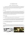
Here is an example hook-up of the PRM-1 front panel c/w the Hardwire Power Board and Two Slagleformer
Modules.
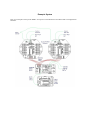
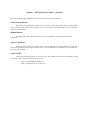
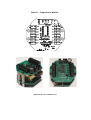
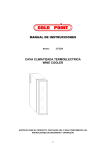
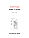
Example System
Here is a picture of the above TAP PRM-1 + Slagleformer system.
The PRM-1 is mounted to the front panel – a demonstration plate from a trade show in this case. The
Hardwired Power Board is behind that (hidden in this picture) and the 2 Slagleformer Modules are behind.
You can see the brown/white power cable and the ribbon cable connecting the Power Board to the
Slagleformer Modules. All that needs to be added to complete the system are the 3 wires per channel for the
input and output RCA jacks.
Front Panel Options and Hook-up
At the time of this writing there are two front panel options. Each is described below.
Option 1 - Full Width Front Panel:
This is a full featured front panel as used in the TAP-X pre-amp. Some of the buttons can be re-set for
OEM customers – most notably the far left button (used as a display toggle on the TAP-X) can be reprogrammed to act as a power on/off button to power up active circuits. To use that function you must use an
Input select board – since that board has the connections to your power relay.
Contact us via e-mail and we can send a cad file of the front panel used in the TAP-X so you can easily
design your own front panel using this board. Functions can be left off by removing the buttons but the location
of buttons and the level control knob can not be moved.
The plus of using this board is that it gives user access and display of all tap functions It does however
require that you layout your front panel to match the board. Bent Audio can do a custom front panel especially
for your application but to do that we need to do a run of at least 100 boards to get the cost per board low
enough.
14”W x 1.5”H x 1”D
Options when ordering the Full Width Front Panel are:
Leds Installed or sent loose?
If your design is using the TAP-X front panel or a panel designed to be exactly like it from the cutout
and thickness point of view then we can install the Leds here for you prior to shipping. If your design is at all
different then we would ship them loose to be installed using your front panel as a jig. This way the leds will
perfectly fit the holes for them in the front panel. If installing them yourself the 'long' lead of the leds is oriented
to the right or up – depending on the led location.
Far Left Button used for Display or Power?
The far left button can be programmed to be a display on off button or to act as a power on/off button –
activating the output located on the Input Select Board to a user supplied power relay.
Option 1 - Full Width Front Panel - continued:
Display ( or Power) Button / Led
For Display Mode:
Each button press toggles between the 2 display modes. When the led is on (display mode on) the
display stays on continuously. When the led is off (display mode off ) the display will be on while you are using
the pre-amp / remote functions and then after a short timeout the display turns off for dark listening. The Red
button on the upper left corner of the remote also toggles the display mode.
For Power Mode:
The panel will have the display dark when the TAP control power is applied to the system. The power
relay (on the Input Select Board) is off. Pressing this button (or the red button on the remote handset) will switch
to power on mode. The unit powers up with the volume right down and the mute on. Pressing it again will cause
a power off of the system. If power is on then the power relay is on and when power is off that relay is switched
off.
TAPE Button / Led
The TAPE button toggles between TAPE Output On and TAPE Output off. See TAPE output
connection details below for information on how the TAPE Output functions.
Mute Button / Led
This button toggles between mute and normal volume modes. When the mute led is on the system is
muted. The mute button on the remote also toggles mute mode. Adjusting volume via the remote or the volume
knob resets the TAP-X to not muted.
Left Channel Volume Display
This numeric led displays the current volume of the left channel.
- In Mute Mode the display reads double dashes “--”
- The lowest volume level (level 1) is -52db attenuation (-60db with resistor modules)
- Unity Gain ( 0db attenuation) is at level 54 (or level 61 with resistor modules)
- The highest volume level (level 61) is +7db of gain (with Autoformer modules)
Volume Knob
Not much to say - it's a volume knob.
Right Channel Volume Display
This numeric led displays the current volume of the right channel.
- In Mute Mode the display reads double dashes “--”
- The lowest volume level (level 1) is -52db attenuation (-60db with resistor modules)
- Unity Gain ( 0db attenuation) is at level 54 (or level 61 with resistor modules)
- The highest volume level (level 61) is +7db of gain (with Autoformer modules)
Option 1 - Full Width Front Panel - continued:
Just to the right of the Right channel numeric display are the source select functions:
Source Down Button:
Each button press changes the selected source to the next lower source. If this button is pressed while
source 1 is selected the source wraps around to source 6. The current source is indicated via a row of leds just
above the source buttons.
Middle Button:
Not often used in DIY/OEM systems but can be programmed for special functions for OEM
applications.
Source Up Button:
Each button press changes the selected source to the next higher source. If this button is pressed while
source 6 is selected the source wraps around to source 1. The current source is indicated via a row of leds just
above the source buttons.
Source LEDs:
Above the source/phase buttons are a row of 6 leds. They indicate the selected source number. The left
most led is source 1 and the right most led is source 6.
Green = Normal (Buffer Mode Off)
Red = HT bypass (lock to volume 'xx').
Front Panel Options and Hook-up - Continued
Option 2- The PRM-1 Module:
This is a small (very small....) PCB that can be used either mounted behind your own front panel or
inside it's own small PRM-1 Enclosure. The PRM-1 Enclosure is particularly useful in DIY and existing product
applications since it mounts via a single hole in the front panel – the same hole that would be used to mount a
typical level control. For DIY projects this makes for easy case construction and in a retrofit application it likely
will mount just fine with no case modifications at all. Soon there will be a flush mount option as well as the
PRM-1 Case. Alternately you can use the MicroTAP Controller (A PRM-1 in a nice tubular case) to run the
system and hide your project box away from sight – making the connection between them with a Fiber Optic
cable. See the document titled “Modular OEM TAP Systems” for ideas and examples of this kind of PRM-1
Application.
The PRM-1 connects to the TAP system via a small 6 pin cable. One end of the cable plugs on to the
PRM-1 circuit board and the other connects to either the Internal TAP Power Board (most common) or if you
use a Goldpoint BSA-1 attenuator board mounted at the front panel then the other end of the cable plugs into the
small header on the BSA-1.
The PRM-1 is a single 7 segment display along with 2 small push buttons – used for volume up and
volume down. The IR remote receiver and 2 leds are also included. All TAP system functions like mute and
source select are supported via remote control operation. Each function is described below:
Volume Up:
Volume up can be run via the upper push button on the PRM-1 module or via the volume up button on
the remote handset. Note that in systems programmed to use power/on off that holding this button for a few
seconds will turn the power on – allowing the system to be turned on without the remote handset.
Volume Down:
Volume Down can be run via the lower push button on the PRM-1 module or via the volume down
button on the remote handset. Note that in systems programmed to use power/on off that holding this button for a
few seconds after mute is reached will turn the power off – allowing the system to be turned off without the
remote handset.
Balance Right / Balance Left:
Even though the PRM-1 only has a single 2 digit level display it can still adjust right/left balance using
the < and > buttons on the remote handset. For user feedback of balance there are 2 small leds just above the
display. If balance is centered then both displays are off. As balance is adjusted to the right the rightmost led will
turn green then orange and finally red as the balance is adjusted further to the right side. The left led behaves the
same way as balanced is adjusted to the left side.
Mute:
If the mute button on the remote handset is pressed the display will change to two dashes ('--') and the
system will mute. Pressing the button again (or pressing a volume up or down button) will un-mute the system
and the display will return to showing the volume level.
Source Selection:
The remote handset is used to change the source selected. The display will show the source number
selected preceded by an underscore (ie for source 5 it will show '_5') and after a few seconds the display will
return to showing the volume level.
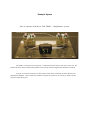
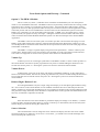
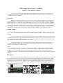
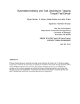
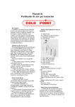
Front Panel Option #2 - PRM-1 Module
PRM-1 Module With Enclosure
2”W x 1.625”H x 0.85”D
The PRM-1 Case simply bolts in place in the same 0.375” hole as a traditional level control.
PRM-1 Module With 6 pin Cable
PRM-1 Module With 6 pin Cable - back side view
PCB Size 1.8”W x 1.3”H x 0.575”D
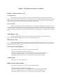
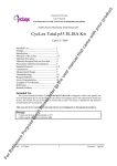
Remote Handset Functions
Display On / Off (The Red button on the upper left corner):
Each button press toggles between the 2 display modes. When the display is 'on' the display stays on
continuously. When the display is set to 'off' the display will be on while you are using the pre-amp / remote
functions and then after a short timeout the display turns off for dark listening.
Buffer Mode (The Black button on the upper right corner):
Pressing this button toggles the currently selected source between 'Normal' and 'Buffer' mode. The
current buffer mode is indicated via the source leds just above the source buttons. Normal mode is indicated by a
green led and 'Buffer Mode' is shown by the source's led turning orange. Note that there are 2 'stops' in buffer
mode. Both these are identical for now – the extra stop is included to allow a future buffer to be easily inserted
into your TAP-X.
Mute (center of volume/balance grid):
This button toggle between mute and normal volume modes. When the mute is on the system is muted
and the display will show double dashes '--'. The mute will be canceled when the volume is adjusted by the
remote handset or by the volume buttons on the front of the pre-amp.
Volume UP / Down ('+' and '-'):
The volume up and down buttons step the volume up or down 1 step (1db) per button press or if held
down continuously they continuously adjust volume.
Balance Left / Right ('<' and '>'):
The Balance Left / Right buttons step the volume to the adjust the balance to the left or the right 1 step
per button press or if held down continuously they continuously adjust balance over to that side. A sliding /
alternating balance is implemented where the level adjustment to move balance alternates from left or right,
etc... This way the overall volume level of the system is maintained. Also you can slide balance over to one side
and then slide it back to the original volume by pressing the opposite balance button. If you hold the button down
constantly while moving back towards center then the balance will stop as it reaches center. This is handy when
adjusting balance back to the middle point.
Source Select Buttons:
The buttons labeled '1' through '6' on the bottom portion of the remote handset directly access each of
the 6 source inputs on the TAP-X. These direct buttons (rather than next/prev) are used to make sure that macro
functions programmed into a (user supplied) advanced programmable handset function repeatably.
4.5”L x 1.5”H x 1”D
Power Supply Board Options
Option 1 – Back Panel Power Board.
This small board is designed to be located at the back panel of the pre-amp but can be installed inside a
chassis if you wish. Contact us via e-mail and we can send a back panel board cad file to use a guide for the
cutout required. This board can only be used with the full width front panel board. If you are using the PRM-1
Module as a front panel then you must use Option2 – the internal power board – described below.
The following functions are included:
Power In:
DC Power is fed into the board via a 2.1mm power connector common on wall supplies throughout the
world. This power jack MUST have the center pin as the hot (+) side of the supply. The actual voltage is not
critical and can range from 7.5V to 12V. It must be DC voltage. A higher voltage can be used but keep an eye on
the heat sinking of the regulator to be sure it never gets hot to the touch. The regulator on this board is designed
to be mounted to the back panel for heat sinking. If mounting this board internally rather than at the back panel
(perfectly fine to do) then be sure that the regulator has adequate heat sinking. A single wire from the GND
point on the board to the central system ground is generally needed.
Display Toggle:
The small toggle switch is used to set the display so it either stays on all the time or so it turns off (for
dark listening) after a command is finished. There are two ways this toggle functions.
1- If you are using the 'power' button on the remote and the far left button of the large front panel board
as a display on/off button (the standard TAP configuration) then the toggle sets the status of display on/off on
power up. After initial power up the remote and front panel buttons set the display mode status. This is how the
toggle switch is used in a TAP-X system. In this type of system it is really not that important to have it there.......
2- If you are using the power button on the remote and the far left button of the wide front panel as a
power button then the display toggle is used 'full time' to decide the display status. Here it is needed in the
system if you want display on/off functionality.
HT Bypass:
This small push button is used to toggle an input between normal mode and HT bypass mode. In HT
Bypass Mode the volume is locked and the input's led turns red. See HT Bypass in the TAP-X pre-amp
instructions for a full description of the HT-Bypass operation. This only makes sense in systems where the TAP
input select boards are used – you must be using the TAP system to select inputs to be able to use the HT-Bypass
functions.
3”L x 1”W
Power Supply Board Options - Continued
Option 2 – Internal Power Board
This small board is designed to be located inside the pre-amp. This board can be used with the full
width front panel board and it must be used if the the PRM-1 Module is used as the display in the system. The
following functions are included:
Power In:
DC Power is fed into the board via 2 screw terminals on the board. It is marked 9V and G (for ground).
The actual voltage is not critical and can range from 7.5V to 12V. It must be DC voltage. A higher voltage can
be used but keep an eye on the heat sinking of the regulator to be sure it never gets hot to the touch. In a PRM-1
system the regulator on this board is designed to be mounted to supplied metal plate that attaches just inside the
front plate via the PRM-1's threaded shaft. If mounting this board internally rather than on the supplied PRM-1
inside plate (perfectly fine to do) then be sure that the regulator has adequate heat sinking. A single wire from the
GND point on the board to the central system ground is generally needed for system grounding purposes.
Display Toggle:
The 2 terminals marked TOG can be wired to a display toggle switch so the display either stays on all
the time or so it turns off (for dark listening) after a command is finished. There are two ways this toggle would
function.
1- If you are using the 'power' button on the remote and the far left button of the large front panel board
as a display button then the toggle sets the initial status of display on/off on power up. After that the remote and
front panel buttons set the display mode status. This is how this toggle switch is used in a TAP-X system. In this
type of system it is really not that important to have it there.......
2- If you are using the power button on the remote and the far left button of the wide front panel as a
power button then the display toggle is used 'full time' to decide the display status. Here it is needed in the
system if you want display on/off functionality.
NOTE:
If a toggle switch does not suit your system plans then there is a small jumper just behind the TOG
terminal. This jumper should be removed if you want to install a display toggle. With this jumper installed the
display will stay on and with the jumper removed the display will come on when a command is issued (ie a
remote button pressed or a front panel button pressed) and then will go dark a few seconds after that command is
complete.
HT Bypass:
This set of 2 terminals marked HT-BYP can be wired to a momentary contact push button to allow HTBypass functions to run in the system. The button would then be used to toggle an input between normal mode
and HT bypass mode. In HT Bypass Mode the volume is locked and the input's led turns red. See HT Bypass in
the TAP-X pre-amp instructions for a full description of the HT-Bypass operation. This only makes sense in
systems where the TAP input select boards are used – you must be using the TAP system to select inputs to be
able to use the HT-Bypass functions.
Hardwire Power PCB – 2.25”L x 1”W
Power Supply Board Options - Continued
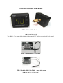
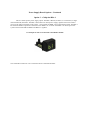
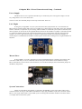
Option 3 – Goldpoint BSA-1
This is a rather specific power supply option. The BSA-1 Board (see below) is a 2 channel (or single
channel balanced) attenuator. The BSA-1 board has an on board power supply regulator that can be used to
power up the other TAP boards in the system – most notably the PRM-1 front panel display board. The BSA-1
has the small header required for connection to the PRM-1 on it's PCB. If the BSA-1 is used to power the
system a heat sink should be added to the BSA-1's regulator.
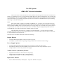
An Example of a BSA-1 Connected to the PRM-1 Module
This combination makes for a nice 2 channel remote controlled attenuator.
Attenuator Boards and Modules
Every TAP system will have at least one and most often two attenuator boards or modules. These are
'run' from the front panel knob/buttons and the remote handset. They can be wired as a passive pre-amp or used
as part of your own active pre-amp system. The pages below show the modules currently offered
Available Attenuator options
Option 1 - Slagleformer Modules
This is the premium attenuator option. As the volume level of the module is turned down the output
impedance drops logarithmically resulting in a device that is particularly well suited to passive pre-amps. It also
makes an outstanding attenuation option in active designs where the cost does not present a problem. The specs
of the module are:
* Continuous 1db Level Steps from -52 to +7db
* Gain Mode Automatically Engages as the level is turned above unity gain (step 54)
* Bandwidth: Below 10 Hz to over 100 KHz ( +/- 1db)
* Right Channel to Left Channel Level Matching: Closer than +/-.05dB
* THD: < 0.008%
* Maximum Input Level: > 10V RMS
Option 2 – Hybrid Attenuator Boards
The 50K version single channel attenuator option is particularly suited to inclusion in an active pre-amp
design. The 10K module works very well as a passive pre-amp if the output to amp cable length is kept very
short and can also be used in an active pre-amp design. It uses a custom designed circuit that is a hybrid design
somewhere between a shunt type and a binary ladder. While essentially a shunt type attenuator the circuit selects
from several series elements depending on the level setting so that the input impedance of the board stays
MUCH more steady than a traditional shunt type level control. This results in lots of volume steps,
comparatively steady input impedance, and a really clean simple signal path. The specs of the module are:
* Continuous 1db Level Steps from -60 to +0db (unity gain)
* Bandwidth (short cable connection to 100K load): Below 10 Hz to over 100 KHz ( +/- 1db)
* Right Channel to Left Channel Level Matching: Closer than +/-.15 dB
* THD: < 0.01%
* Maximum Input Level: > 10V RMS
Option 3 – Goldpoint BSA-1 Board
This 2 channel board can be used in an active pre-amp design or as a passive pre-amp attenuator. It is a
binary type circuit that gives many level steps and 2 channels on one board with a minimum of parts used. This
is the lowest cost option (per channel) but still provides outstanding sonics. The specs of this module are:
* Continuous 1db Level Steps from -60 to +0db (unity gain)
* Bandwidth (short cable connection to 100K load): Below 10 Hz to over 100 KHz ( +/- 1db)
* Right Channel to Left Channel Level Matching: Closer than +/-.15 dB
* THD: < 0.01%
* Maximum Input Level: > 10V RMS
Attenuator Boards and Modules - Continued
Option 1 – Slagleformer Module Connection and Setup.
These modules are Autoformer based attenuators. Each module can adjust volume from -52db to +7db
in 1 db steps. At the heart of the module is the Autoformer made by Dave Slagle at Intact Audio. This sheet will
concentrate on the hook-up and use of the module.
Each Slagleformer is a one channel attenuator. Two modules are required in a stereo pre-amp. Four
modules (Two per channel) are required to run true balanced attenuation.
Think of each module as a deck of a stepped attenuator. They can be located anywhere in the chassis –
usually choosing a location in the flow of the signal path to keep wiring short and clean.
The switching for level/gain, and mute are all contained in the module – no wiring of individual volume
taps is needed. This results in a much cleaner and shorter signal path than in other Autoformer and Transformer
pre-amps. This also makes for a simple 3 wire connection (In/Out/Gnd) just as a normal single channel volume
pot would wire.
Important Note: When making connection that the 3 wires must extend through the top board in to the
bottom board – making connection at both the top and bottom board solder pads. These connection points are
aligned with one another to make this clean and easy to do.
The 3 connections are:
1- 'IN':
This is the connection to the input select board or in the case of a single input unit from the Input RCA.
2-'OUT':
This is the connection to the out terminals on the Input select board or directly to the output RCA.
3- Ground:
This is the connection to the system ground point.
Finally the TAP ribbon cable header is connected to the BentBus via the 10 pin ribbon cable routed within the
chassis.
There are a few user selectable jumpers on the top circuit board. These are:
Left / Right:
These 2 jumpers are used to set the right/left balance function of the module. If a jumper is inserted at
the left 'L' position the module will become a left channel module. If one is inserted at the right 'R' position then
the module is set to be a right channel module. As balance is adjusted the module will respond accordingly. If
neither jumper is installed then the module is neither right or left and will not change level as right/left balance is
adjusted.
GND:
When installed this jumper connects the audio ground to the control circuit ground. Most systems want
a connection between these grounds at some point but each pre-amp design will have it's own grounding plan. I
like to make this connection via a single wire from the power supply board to the central system ground (not
installing this jumper) but the jumper is included as a handy option for experimenting and testing.
Option 1 – Slagleformer Module
Approx 2.75”L x 2.75”W x 2.5”H
Attenuator Boards and Modules - Continued
Option 2 – Hybrid Resistor Attenuator Board Connection and Setup
These modules are resistor based attenuators. Each module can adjust volume from -60db to 0db (unity
gain) in 1 db steps. They are available in both a 10K and 50K impedance. This sheet will describe the hook-up
and use of the module. For a description of the circuit and how it fits with other module options see the text
above in the 'Module Types' section.
Each Hybrid Board is a one channel attenuator. Two modules are required in a stereo pre-amp. Four
modules (Two per channel) are required to run true balanced attenuation.
The small 1-1/2” x 3” Hybrid board can be located anywhere in the chassis – it is suggested that you
locate it in the 'flow' of the signal path to keep that path as short as possible. They can be stacked one on the
other using M-F standoffs – handy if pairing them up for balanced operation.
Each Hybrid board is like 1 deck of an traditional attenuator and it connects very much like a traditional
3 wire pot. The location of the connection points on the PCB are chosen to keep the signal path on the circuit
board as short as possible.
The 3 connections are:
1- 'IN':
This is the connection to the input select board or in the case of a single input unit from the Input RCA
Jack.
2-'OUT':
This is the connection to the out terminals on the Input select board or directly to the output RCA
jack(s).
3- Ground:
This is the connection to the system ground point.
Finally the TAP ribbon cable header is connected to the BentBus via the 10 pin ribbon cable routed within the
chassis.
3”L x 1.5”H x 0.6”H
Attenuator Boards and Modules - Continued
Option 2 – Hybrid Resistor Attenuator Board Connection and Setup - Continued
There are a few user selectable jumpers on the circuit board. These are:
Left / Right:
These 2 jumpers are used to set the right/left balance function of the module. If a jumper is inserted at
the left 'L' position the module will become a left channel module. If one is inserted at the right 'R' position then
the module is set to be a right channel module. As balance is adjusted the module will respond accordingly. If
neither jumper is installed then the module is neither right or left and will not change level as right/left balance is
adjusted.
GND:
When installed this jumper connects the audio ground to the control circuit ground. Most systems want
a connection between these grounds but as in all grounding each pre-amp design will have it's own grounding
plan. I like to make this connection via a single wire from the power supply board to the central system ground
(not installing this jumper) but the jumper is included as a handy option for experimenting and testing.
TRIM:
There is also a TRIM header on the board. Although not used in a 2 channel pre-amp design the Hybrid
modules can be ordered with trim function active. In that case there is a mating trim up/down PCB that can be
used to adjust the offset level of that particular board. The TAP-X system expansion modules are shipped this
way. Once trim is set the module follows up and down with the TAP system modules but has it's level slightly
higher or lower than the rest – depending on the amount of trim. If you think you need this function in your
design please contact us to discuss it further.
Attenuator Boards and Modules - Continued
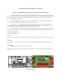
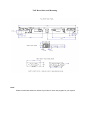
Option 3 – Goldpoint BSA-1 Board Connection and Setup
The Goldpoint BSA-1 Board can be run with a small on board pot to act as a 1db step size non-remote
control attenuator or become part of a TAP system. See www.goldpt.com for information on that non remote
configuration. Here we will describe it's use in a TAP system.
These modules are resistor based attenuators. Each module can adjust volume from -60db to 0db (unity
gain) in 1 db steps. Each BSA-1 Board is a 2 channel attenuator. One module is required in a stereo pre-amp.
Two modules are required to run true balanced attenuation. This section will describe the hook-up and use of the
module.
The small 1-1/2” x 2-3/4”” BSA-1 board can be located anywhere in the chassis – it is suggested that
you locate it in the 'flow' of the signal path to keep that path as short as possible. They can be stacked one on the
other using M-F standoffs – handy if pairing them up for balanced operation.
Each BSA-1 board is like a traditional 2 deck stereo attenuator and it connects very much like a
traditional 3 wire pot.
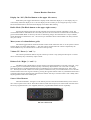
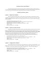
The 3 connections are:
1- 'INA and INB':
These are the connection point to the hot side of the input select switch or directly to the hot of the input
rca jacks on a single input system.
2-'OUTA and OUTB':
This is the connection to the hot side of the output RCA jack(s).
3- Ground:
This is the connection to the system ground point.
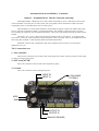
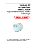
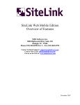
INPUT 'B'
INPUT 'A'
9VDC
GND
OUTPUT 'B'
OUTPUT 'A'
ANALOG GROUND
6 PIN CABLE
TO PRM-1
Goldpoint BSA-1 Board Connection and Setup – Continued
Power Supply:
The BSA-1 has it's own 2 position terminal strip to connect DC power. The typical voltage is 9V but
any voltage from 7.5V to 12V can be used.
There are a few user selectable jumpers on the top circuit board. These are:
Left / Right:
If using only a single BSA-1 in your system then leave these jumpers both off – the 2 channels of a
BSA-1 always operate together and so they can not adjust up or down relative to each other. In this case right/left
balance function is not possible. If you are using 2 BSA-1 Boards in a balanced system (XLR connections) then
these 2 jumpers can be used to set the right/left balance function of the modules. If a jumper is inserted at the left
'L' position the module will become a left channel module. If one is inserted at the right 'R' position then the
module is set to be a right channel module. As balance is adjusted the module will respond accordingly. If
neither jumper is installed then the module is neither right or left and will not change level as right/left balance is
adjusted.
Master/Slave:
If using a BSA-1 in a TAP system then you must set both M/S jumpers to the Slave (S) position. This
will set the board ready to receive commands from the front panel board and the remote handset. If using a
BSA-1 stand alone as a non-remote control attenuator (via it's PCB mounted pot) then set both these jumpers to
the Master (M) position.
System Connections:
Finally the TAP ribbon cable header is connected to the BentBus via the 10 pin ribbon cable routed
within the chassis. If using it with a PRM-1 Module then simply plug the PRM-1 6 pin micro connector into the
BSA-1. The 10 pin ribbon cable is only needed if you are running other attenuator modules in the same chassis
or an Input Select board in the system.
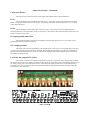
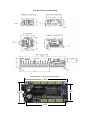
Input Select Board
This board can be used in a TAP system to allow remote control of input source selection. The Input
Select Board can be ordered either with or without RCA connectors installed. If ordering with RCA connectors
installed then you will have to lay out your back panel to match the position of these connectors. Please contact
us here for drawings to use as a guide with the back panel cutout.
The Board has the following specs:
–
–
–
–
6 RCA Inputs
Tape Output
2 RCA Outputs
Power Out Terminal (for user supplied power relay)
The connection of each of these is described below.
Input Jacks:
If using the installed RCA connectors this part is easy – see below for the PCB connection points to the
downstream circuits. If hardwiring your own RCA jacks to the board just wire the ground side of each jack to
the hole closest to the board edge and the hot side of the RCA connection to the adjacent hole (right next to each
input's relay). Each Input is marked for input number and right or left – ie. 1L is input 1 left, 3R is input 3 right,
etc.....
Tape Output:
The Tape Output is a set of connections to connect to a recording device like a tape deck or a CDR,
etc.... When the Tape Out function is on the signal from the currently selected input jack is fed directly to the
Tape Out jacks. If Tape Out is off then the signal is disconnected. Each is marked for Left/Right and the ground/
hot connection is the same as for the input jacks.
Output Jacks:
If you are using the Input Select Board with the two Output RCA jacks installed from the factory then
they will be routed on the PCB to the out connections (see below). If you are not using the factory installed jacks
then it is suggested you simply connect the output of your circuit directly to the output RCA jack(s). Note there
is a set of Mute relays at the output jacks. These will short the outputs (and drop the input connection) when the
mute function is engaged – if hardwiring your output circuits directly to the output jacks then you can wire over
from the out PCB pads to these jacks to get a true mute function in the system.
Power Out:
For most DIY projects it is hard to beat a simple toggle switch for power – it's much easier than relays,
etc to implement! For OEM systems where you need remote handset power on/off function this 2 terminal
connection can be used to power a relay that in turn will power on and off the active circuits in your design. The
relay must be a 5V relay that draws under 100mA. Also be sure to install a spike protection diode or choose a
relay with a diode built in and pay attention to the polarity of the relay when wiring to the PCB board terminals.
Provided you have ordered your front panel board programmed for Power on/off function the relay will close
when the power function is switched on and open when the power function is switched off – via either the front
panel button or the remote handset. To use this function you must design the power routing of the system so the
TAP power supply board always has power to it – so the TAP system will always be ready to activate the power
on/off function.
Input Select Board - Continued
Connection Points:
There are several connection points on the Input Select Board. Each is described below:
IN-L:
This is the left channel input HOT connection point – most often wired to the Left channel attenuator
board or to an input buffer circuit in your design. The positive side of the selected input (from 1 to 6 ) will be
connected to this point.
IN-R:
This is the Right channel input HOT connection point – most often wired to the Right Channel
attenuator board or to an input buffer circuit in your design. The positive side of the selected input (from 1 to 6 )
will be connected to this point.
IG (input ground) and GND:
These points are both connected to the input RCA jack grounds. Route a wire to your main system
ground point from this PCB ground point.
OG (output ground):
This point connects to the output RCA jack grounds. Next to this point is a set of pads that can be used
to connect the input and output grounds on the PCB. The ground plan internally of your design will dictate if a
jumper if placed between these two points or if the Out and Input grounds remain separate or are connected at
the system ground point only.
L & R (by the output RCA jacks):
These points connect to the respective output RCA jack's hot connection. If not using factory installed
RCA jacks just connect your output hot connection directly to the output RCA jacks. If hardwiring directly to the
out jacks you may run a wire from these points to each output RCA jack to make use of a true mute function.
Note that even if you are not using this output 'hard mute' that the TAP attenuator boards will mute when the
TAP system is in a mute state.
8.5”L x 1.75”W
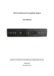
TAP Board Sizes and Mounting
Note:
Please contact Bent Audio for dxf files if you'd like to use a cad program for your layouts.
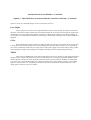
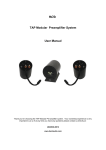
TAP Board Sizes and Mounting
Goldpoint BSA-1 Stereo Attenuator Module
2.875”
1.25”
1.625”
2.50”