1
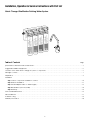
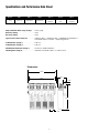
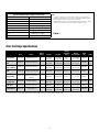
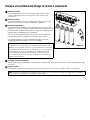
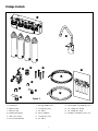
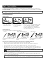
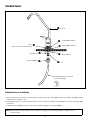
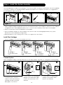
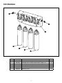
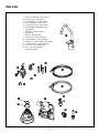
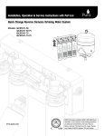
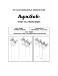
Installation, Operation & Service Instructions with Part List Quick Change Ultrafiltration Drinking Water System Models: QCUF www.pura.com Attention PURA Customer: This system is intended for use on potable water supplies or disinfected water containing cysts. Do not use where water is microbiologically unsafe or with water of unknown quality. If bacterial contamination is present, a recognized method of water disinfection is required. Check with your public works department for applicable local plumbing and sanitation codes. Follow your local codes if they differ from the standards used in this manual. The PURA Quick Change Drinking Water System contains a replaceable ultrafiltration membrane filter which is critical for the effective reduction of Total Dissolved Solids. The filtered water should be tested periodically to verify that the system is performing properly. Safe Practices Throughout this manual there are paragraphs set off by special headings. Note: Note is used to emphasize installation, operation or maintenance information which is important, but does not present any hazard. Example: Note: The nipple must extend no more than 1 inch above the cover plate. Caution!: Caution is used when failure to follow directions could result in damage to equipment or property. Example: Caution! Disassembly while under water pressure can result in flooding. Warning!: Warning is used to indicate a hazard which could cause injury or death if ignored. Example: Warning! Electrical shock hazard! Unplug the unit before removing the timer mechanism or cover plates! Serial Number The serial number is located on the rear of the UF manifold housing. Record this number on the warranty page located at the end of this manual. Note: Do not remove or destroy the serial number. It must be referenced on requests for warranty repair or replacement. Serial Number Label U - MM-DD-YY-XXXXXX Data Plate Label Containing Model # Date of manufacture Serial Code This publication is based on information available when approved for printing. Continuing design refinement could cause changes that may not be included in this publication. Warning! If incorrectly installed, operated or maintained, this product can cause severe injury. Those who install, operate, or maintain this product should be trained in its proper use, warned of its dangers, and should read the entire manual before attempting to install, operate or maintain this product. 1 Installation, Operation & Service Instructions with Part List Quick Change Ultrafiltration Drinking Water System Table of ContentsPage Specifications and Performance Data Sheet . . . . . . . . . . . . . . . . . . . . . . . . . . . . . . . . . . . . . . . . . . . . . . . . . . . . . . . . . . . . . . . . . . . 3 Suggested Installation Equipment . . . . . . . . . . . . . . . . . . . . . . . . . . . . . . . . . . . . . . . . . . . . . . . . . . . . . . . . . . . . . . . . . . . . . . . . . . . . 5 Overview of the PURA Quick Change UF System’s Components . . . . . . . . . . . . . . . . . . . . . . . . . . . . . . . . . . . . . . . . . . . . . . . . . . 6 Package Contents . . . . . . . . . . . . . . . . . . . . . . . . . . . . . . . . . . . . . . . . . . . . . . . . . . . . . . . . . . . . . . . . . . . . . . . . . . . . . . . . . . . . . . . . . 7 Preparation . . . . . . . . . . . . . . . . . . . . . . . . . . . . . . . . . . . . . . . . . . . . . . . . . . . . . . . . . . . . . . . . . . . . . . . . . . . . . . . . . . . . . . . . . . . . . . . 8 Installation Step 1 Select Component Installation Locations . . . . . . . . . . . . . . . . . . . . . . . . . . . . . . . . . . . . . . . . . . . . . . . . . . . . . . . . . . . . 10 Step 2 Faucet Installation . . . . . . . . . . . . . . . . . . . . . . . . . . . . . . . . . . . . . . . . . . . . . . . . . . . . . . . . . . . . . . . . . . . . . . . . . . . . . . . 11 Step 3 Install Adapter Valve on Water Supply . . . . . . . . . . . . . . . . . . . . . . . . . . . . . . . . . . . . . . . . . . . . . . . . . . . . . . . . . . . . . . 13 Step 4 Install Filter System Assembly . . . . . . . . . . . . . . . . . . . . . . . . . . . . . . . . . . . . . . . . . . . . . . . . . . . . . . . . . . . . . . . . . . . . . . . 14 Step 5 Start Up . . . . . . . . . . . . . . . . . . . . . . . . . . . . . . . . . . . . . . . . . . . . . . . . . . . . . . . . . . . . . . . . . . . . . . . . . . . . . . . . . . . . . . . . 15 Service and Maintenance . . . . . . . . . . . . . . . . . . . . . . . . . . . . . . . . . . . . . . . . . . . . . . . . . . . . . . . . . . . . . . . . . . . . . . . . . . . . . . . . . . 16 Parts Breakdown . . . . . . . . . . . . . . . . . . . . . . . . . . . . . . . . . . . . . . . . . . . . . . . . . . . . . . . . . . . . . . . . . . . . . . . . . . . . . . . . . . . . . . . . . . 17 Troubleshooting . . . . . . . . . . . . . . . . . . . . . . . . . . . . . . . . . . . . . . . . . . . . . . . . . . . . . . . . . . . . . . . . . . . . . . . . . . . . . . . . . . . . . . . . . . . 19 Warranty Information . . . . . . . . . . . . . . . . . . . . . . . . . . . . . . . . . . . . . . . . . . . . . . . . . . . . . . . . . . . . . . . . . . . . . . . . . . . . . . . . . . . . . . 20 2 Specifications and Performance Data Sheet Model # QCUF Part # 1340201-60 Stage 1 Sediment Filter Stage 2 Stage 3 Stage 4 Faucet Sediment Filter Ultrafiltration Membrane Activated Carbon Filter Chrome or Standard Daily Production Rate L/day (G/day) ����� 2725.5 (720) Efficiency Rating����������������������������������������� 100% Recovery Rating ����������������������������������������� 100% Typical System Flow Sequence����������������� Sediment Filter Sediment Filter Ultrafiltration Membrane Activated Carbon Postfilter Dispensing Faucet Sediment Filter (Stage 1). . . . . . . ������������� 5 Micron Sediment Filter (Stage 2) ��������������������������� 5 Micron Ultrafiltration Membrane (Stage 3)����������� 0.2 Micron Ultrafine Filtration Polishing Filter (Stage 4)����������������������������� Granular Activated Carbon or Carbon Block Dimensions 15.8” 4.7” 14.3” 2.0” 13.1” 2.5” 3 Recommended Influent Water Characteristic Pressure 40 - 100 psi Temperature 40 - 77 ºF pH 5 - 10 Chlorine2 0 - 3 ppm (0 - 3 mg/L) Chloramine 0 - 3 ppm (0 - 3 mg/L) Turbidity 0 - 10 NTU Hardness3 0 - 10 gpg Iron 0 - 1 ppm (0 - 1 mg/L) Bacterial Quality Potable Notes 1. A softener is strongly recommended for water over 10 gpg hard. Installing a system without a softener on water with hardness higher than 10 gpg will reduce the life of the membrane. 2. Additional information on factors that affect UF performance can be found in the “Performance & Technical Information” section. Table 1 Filter Cartridge Specifications Part # Purpose Micron Rating Working Temperature Working Range Pressure Range Capacity Flow Rate 0.5 gal/min (1.9 liters/min) 4-38° C (40-100° F) Rated Life* STAGE 207-689 kPa (30-100 psi) 6 Months 1 Sediment Filter 41407001 Sediment Reduction 5 2000 gallons (7570 liters) Carbon Block Filter 41407002 Chlorine Taste and Odor 5 2000 gallons (7570 liters) 0.5 gal/min (1.9 liters/min) 4-38° C (40-100° F) 207-689 kPa (30-100 psi) 6 Months 2 or 4 Carbon Block Filter - 50 Micron 41407006 Chlorine Taste and Odor 50 2000 gallons (7570 liters) 0.5 gal/min (1.9 liters/min) 4-38° C (40-100° F) 207-689 kPa (30-100 psi) 6 Months 2 GAC Carbon Filter 41407004 Polishing - Taste and Odor – 2000 gallons (7570 liters) 0.5 gal/min (1.9 liters/min) 4-38° C (40-100° F) 207-689 kPa (30-100 psi) 6 to 12 Months 4 pH Booster Filter Cartridge 41407007 Raise pH of water and removal of chlorine, taste and odor – 750 gallons (2835 liters) 0.5 gal/min (1.9 liters/min) 4-38° C (40-100° F) 207-689 kPa (30-100 psi) 6 to 12 Months 4 UF (Hollow Fiber) Membrane 41407005 Ultra Fine Filtration 0.2 2000 gallons (7570 liters) 0.5 gal/min (1.9 liters/min) 4-38° C (40-100° F) 207-689 kPa (30-100 psi) 12 Months 3 Carbon Block – 1 Mic Filter 41407009 Chlorine Taste and Odor, Particulate Reduction 1 750 gallons (2835 liters) 0.5 gal/min (1.9 liters/min) 4-38° C (40-100° F) 207-689 kPa (30-100 psi) 6 to 12 Months 2 or 4 Scale Reduction 41407010 Scale Reduction – 2000 gallons (7570 liters) 0.5 gal/min (1.9 liters/min) 4-38° C (40-100° F) 207-689 kPa (30-100 psi) 6 Months 1 or 2 * The performance and life of an ultrafiltration membrane or filter element is highly dependent upon pressure, temperature and water quality. 4 Suggested Installation Equipment 1 2 3 4 6 7 8 5 Recommended Tools 1. Utility Knife 12 10 2. Flathead Screwdriver 3. Phillips Screwdriver 11 4. Center Punch 5. 7/8” Stepped Drill Bit 6. Finish Hole Saw 7. Porcelain Saw 8. 1/8” & 3/8” Drill Bits 9. Heavy Duty Drill 10. Work Light 11. 2 Adjustable Wrenches 12. Pressure Gauge Figure 1 5 Overview of the PURA Quick Change UF System’s Components Manifold Assembly The manifold assembly serves as the functional hub of the PURA system by directing the flow through each of the system’s main components. Sediment Prefilters The sediment prefilters screen out particulate material, such as dirt, sand, or rust, which may clog the ultrafiltration membrane. Ultrafiltration Membrane The Ultrafiltration Membrane (3) mechanically removes microscopic impurities. It consists of a semipermeable membrane wound around a perforated tube. Product water diffuses through the membrane while impurities become trapped in the membrane. The UF membrane featured in the PURA system offers exceptional contaminant adsorption, application versatility, and long life. The sediment prefilters must be maintained properly to prevent clogging and premature failure of the UF membrane. Note: This preservative must be flushed from membrane before use. If ingested it may cause irritation of the gastrointestinal tract, colic, diarrhea, or other similar symptoms. The manufacturer recommends discarding all the product water for at least one hour of operation before drinking or use in food preparations. WaterGroup highly recommends discarding the product water for a full 24 hours to flush the preservative and to properly hydrate the membrane for maximum performance. Figure 2 Activated Carbon Polishing Filter The activated carbon polishing filter (4) adsorbs any residual tastes and odors just before the water is delivered through the faucet. Dispenser Faucet The PURA faucet (5) allows the product water to be drawn from the system with a simple rotation of the handle. Note: Cleanliness is essential in the Preparation procedure. Be sure to wash your hands thoroughly before handling filters. The use of surgical gloves is strongly recommended. 6 Package Contents 1 6 2 3 7 4 5 10 13 16 14 11 8 9 12 15 Figure 3 1. UF Manifold 7. Piercing Saddle Valve 13. 4X #10 Phillips Self Tapping Screws 2. Sediment Filter 8. Locking Clip (3/8”) 14. 1/4” Tubing ( 4 ft. White) 3. Sediment Filter 9. 3/8” Elbow 15. 3/8” Tubing (4 ft. Blue) 4. Ultrafilter Membrane 10. Faucet Adapter 16. Installation Template Sheet 11X17 5. Carbon Block Filter 11. Locking Clip (1/4”) 6. Faucet and Hardware 12. 1/4” Elbow 7 Product Information This manual covers the technical aspects of PURA Quick Change drinking water systems. It is important to read this manual thoroughly so that you can properly apply, install, and service these systems. The substances reduced by this system are not necessarily in the customer’s untreated water. Warranty A limited warranty is extended to the original end user from WaterGroup. This warranty is printed on the back cover of the Owner’s Guide. Application Guidelines The PURA system is designed for use on potable water supplies meeting the guidelines outlined in Table 1. The system should be installed on a home’s cold water line. The flushing stream should discharge through an approved siphon break. Installation of this system must comply with state and local laws and regulations. Package Content The PURA system is shipped from the factory in carton: Note: The filter elements are shipped in their own sealed packaging. This will help to simplify preparation of the system and to maximize the shelf life of the UF membrane element. Preparation Tubing Connectors The PURA system features reliable and convenient push-to-connect tubing connectors. Tubing is easily connected and disconnected from these fittings as follows. Quick-Connect Fitting Insertion & Removal of Plastic or Copper Tubing 2. Tube is secured in position. 3. Push in collet from both sides to release tubing. 1.Simply push in tube to attach. Figure 4 Connect: Cut the tubing squarely with a sharp knife. Be careful not to crush the tubing. To avoid leaks, make sure the tubing end is smooth and free of burrs and abrasions. Lubricate the end of the tube with water or a light coat of silicone and push the tube end firmly into the fitting. You should feel it push past the O-ring. Avoid bending the tubing sharply away from the fitting. Disconnect: Hold the collar against the fitting body and pull the tube from the fitting. In the unlikely event that the connection leaks, remove and recut the tubing. Check the inside of the fitting for debris or O-ring damage. Reconnect. Push-to-connect tubing connectors grip the outside diameter of the tube. To help assure a reliable connection, it is important to use high quality tubing with a consistent outside diameter. 8 1.Cut tube squarely with a sharp knife. Installation The exact placement of the components will vary by installation. Although shown beneath a sink, it may be installed in a basement, crawl space, or in an adjacent cabinet. Regardless of where the system is installed, the flow sequence described by (figure 7) must be observed. The PURA drinking water system is designed to be mounted near a sink for easy access to cold water. Lengths of 1/4-inch and 3/8-inch OD plastic tubing will be required to make this installation. Evaluate the installation site to determine the easiest path for the plumbing to follow. Take care to make the installation as neat as possible. Pura Faucet STEP 2 STEP 3 Cold Water Supply STEP 4 UF Manifold 3/8” Product Water Line (Blue) 1/4” Feed Line (White) The additional Point of use connection (Icemakers etc) can be tapped from here with the use of reducing Quick Connect Tee (14” X 3/8” X 3/8”) (Part # PP30121208W). Figure 7 9 The following steps will enable you to install the system quickly and orderly. Some variation may be necessary depending on the installation. See page 4 for a check list of tools and materials. Typical installations follow this sequence: 1. Select Component Installation Locations 2. Faucet Installation 3. Install Adapter Valve on Water Supply 4. Install Filter System Assembly 5.Start-Up Step 1 – Select Component Installation Locations • Dispenser Faucet – The faucet is designed to be mounted on the rear lip of the sink. It may be installed in an existing sprayer attachment hole or in a hole drilled at the time of installation. It may also be mounted to an adjacent counter top. It should be positioned so that water is dispensed over the sink. A 7/8” diameter hole is required. • Important considerations: • Access to the bottom (undersink) of the faucet is required for attachment of product water line. • There should be no undersink obstructions which would prevent smooth tubing runs to the drain connection, or UF module assembly. • Filter System Assembly – The filter system assembly is designed to be mounted on any rigid vertical surface such as a cabinet sidewall, sheetrock in exposed stud. It should be positioned such that there is access to an inlet water source and drain. The installation should also allow convenient access for servicing. • Inlet Water Supply Connection – Once a location is chosen for installation of the filter system assembly, select a nearby cold water line to provide the water source for the system. Note: Follow all local plumbing codes when connecting to service water. 10 Step 2 – Faucet Installation To simplify its access and installation, we suggest you install the faucet on the rear lip of the sink. It should be evenly positioned with the sink faucet and spray attachment. Should the spray faucet hole not be available for the installation, the sink must be drilled. Note: It is recommended retaining the services of a professional counter top craft person when a hole is needed in granite or other specialty counter top materials. Sink Drilling Instructions Stainless Steel Sink 1. Select and mark the proper faucet location. 3. Drill a 7/8” hole in the sink using a stepped 7/8” drill bit. If no stepped bit is available, start by drilling a 1/4” hole. Using this hole as a starting point progressively drill larger holes. Increase drill size by 1/8” until you reach a 7/8” hole. 2. Center punch hole to provide a starting point for your drill. Porcelain Enamel Sink Follow these basic guidelines when drilling a porcelain sink: Pilot Drill Spring Loaded Porcelain Saw Penetrate the porcelain to the base material. Protect the surrounding porcelain material. Finish Hole Saw Use the appropriate tool to drill the base material. One proven tool is the Relton porcelain cutter kit when used with a slow speed drill (300-400 rpm). • Drill a pilot hole through the porcelain and base material with the carbide tip drill. • Build a putty dam around the drill area. Add enough water to lubricate cutters and reduce cutting noise. • Insert the porcelain cutter into the drill. Place the drill tip in the pilot hole. Check for free movement. • Apply light pressure to the cutter tool and start the drill motor at low speed (300-400 rpm). When the initial cut has been made in the porcelain, speed may be increased. After a complete ring has been cut through the porcelain, change over to the metal cutter. Avoid contacting the outer rim of cut porcelain when drilling. Caution! Avoid high drill speed during penetration of porcelain. A single speed drill can be used at a slow speed by switching it on and off quickly. • Use a slow speed and light pressure to cut away the porcelain. • Stop when you reach the metal under the porcelain. Remove the cutter and clean the porcelain chips from the surface. Continue cutting through the metal. Note: C eramic tile counters should be treated like porcelain when penetrating the surface, then treated as metal to complete the hole with carbide drills. Formica countertops can be drilled with a high-speed wood drill. 11 Standard Faucet 1 2 Base (Remove white protective film) 3 Lock Washer Faucet Adapter 4 6 5 8 7 Faucet Small Rubber Washer Large Rubber Washer Plastic Washer Nut Drinking Water Line to Faucet (3/8” Blue Tubing) Standard Faucet Installation 1. R emove white protective film from faucet base. Install faucet body, small rubber washer, metal base, and large rubber washer above sink (items 1-4). 2. Install plastic washer, lock washer and nut (items 5-7) onto faucet stem below sink and tighten. Be sure to properly align the faucet. 3. Install the faucet adapter (item 8). Connect the 3/8" blue tubing to the faucet adapter. Note: M ake certain that the tubing is all the way into the fitting; once inserted pull lightly to make sure it is locked in place. 12 Step 3 – Install Adapter Valve on Water Supply 1. L ocate shut off valves on water lines under sink. To identify hot & cold supply pipes, turn on both faucets and let water run. Hot water pipe will be the warmer pipe. Turn off cold water supply valve. Open sink faucet to drain line. Some mixing faucets may require shutting off the hot water valve as well. 1 OK Caution! Do not turn valve handle before or during installation of saddle valve. Be sure piercing lance does not protrude prior to installing valve. Caution! If no shut off valve is installed under sink, close main water valve. Do not install feed water assembly on hot water line. 2. H old saddle valve against pipe. NO! 2 3 4 3. S lide back plate into position. •U se small radius side for 3/8”copper pipe. •U se large radius side for 1/2”copper pipe. 4. T ighten screw firmly so saddle valve is held securely in place. Do not crush tube. 5. C onnect feed tubing to valve body using compression fitting. • Slide nut and plastic sleeve onto tubing. • Install insert into plastic tubing. • Slide into valve body and tighten nut securely. NOTE: Do not use brass sleeve on plastic tubing. 5 Insert Plastic Sleeve Nut 1/4” Tubing 6 7. Once all lines are connected to the UF system turn on cold water supply. Turn Valve counter-clockwise and check for any leaks. Run water from the faucet to clear any debris caused by installation. 6. Turn handle clockwise until firmly seated and piercing valve has extended fully. NOTE: If flow from sink faucet is reduced, clean faucet aerator. 13 Step 4 – Install Filter System Assembly The mounting bracket contains four mounting slots. The holes are sized to accept #10 round head wood screws (supplied). Some types of surfaces such as particle board or drywall, may require the use of plastic screw anchors or toggle bolts to provide adequate support for the unit. 1 2 3 4 12" Figure 15 1. T ape the paper template included with this unit to the wall with the base of the template on the bottom of the cabinet (or higher). Be sure to leave adequate space (8 1/2” or more from the centerline) on both sides of the template. 2. Drill 1/8” hole at each location as indicated on the template. 3. R emove template. Thread one of the included wood screws into each hole leaving approximately a 1/2” space between the screw head and mounting surface. 4. Hang the bracket on the mounting screws. If unit is loose, tighten the screws further. Install Filter Cartridges 1.Twist the cartridge to lock it into the manifold. (as shown) Stage 1 Sediment Filter Stage 2 Sediment Filter Stage 3 Ultrafiltration Membrane Stage 4 Carbon Block Filter Connect System When cutting plastic tubing, use a sharp utility knife. Cut the tubing squarely. See page 7 for cutting and connecting tubing. 2 1 White 1.Connect quick connect elbows to the three open connection locations on the unit. Firmly push the fittings into place, then pull back lightly to lock them in. 2.Connect 1/4-inch OD white plastic tubing from the feed water supply source to the system inlet on the manifold. 14 3 Blue 3.Connect 3/8-inch OD blue plastic tubing from the product water faucet to the manifold. 4 4. Attach locking clips to each white elbow fitting. Clips should slide in behind collet on the fittings. Step 5 – Start-Up 1. Check system to verify all components are correctly installed 2. Open inlet valve and tank valve. 3. Check system thoroughly for leaks. If any are found, shut off both inlet and tank valves and correct the issue. 4. Open faucet to flush carbon fines & sanitization solution. After allowing the system to run for 20 minutes turn off the faucet 5. System is ready to use Warning! Do not drink water produced by the system until the start-up procedure has been followed completely! 15 Service and Maintenance Service Schedule To keep the PURA system operating properly, it is necessary to change the filters and sanitize the system periodically. Typically, this should be done on an annual basis. Service frequency may vary depending on local water conditions. High sediment, chlorine, turbidity, or hardness levels may require more frequent service. Use the following as a guide. As needed Clean the faucet with a soft cloth, avoid abrasive cleaners. At least once in 6 months Replace • Stage 1 and 2 S ediment Filters (41407001) Rotate sediment filters 3 months after changing (swap stage 1 & stage 2) At least once in 12 months Replace • Stage 3 Ultrafiltration Membrane (41407005) • Stage 4 Carbon Block Filter (41407002) Sanitize the system 16 Parts Breakdown 6 5 1 2 2 3 4 # Item # Description 1 134040U Manifold, Quick Change Ultrafilter, 4 Stage 1 2 41407001 Cartridge, Quick Change Sediment Filter - Stage 1 & 2 2 3 41407002 Cartridge, Quick Change Carbon Block - Stage 4 1 4 41407005 Cartridge, Quick Change Ultrafiltration Membrane - Stage 3 1 5 33501064 Elbow,1/4” Stem 1 6 33501071 Elbow,3/8” Stem 1 17 Qty. Other Parts 1.Faucet & Hardware – Part # 92192 2.Piercing Valve - Part # 92276 3.Locking Clip (3/8") – Part # 92346 4.Faucet Adapter – Part # 92652 5.Locking Clip (1/4") – Part # 92345 6.4x #10 Phillips Self Tapping Screws 7.1/4" Tubing (4ft White – Part # 115200) 8.3/8" Tubing 4ft Blue – Part # 87600) 9 O-ring, Small – Part # 41407554 10.O-ring, Medium – Part # 41407555 11.Replacement Filter Head – Part # 92804 12.Compact Elbow – Part # 41407558 13.1/4” Elbow – Part # PP0308W 14.3/8” X 1/4” Stem Adapter – Part # PP061208W 4 1 6 2 7 5 3 9 8 12 11 10 13 18 14 Troubleshooting Guide If a problem cannot be corrected through the use of this troubleshooting guide please have the following information ready prior to calling the 1-800 number on the back of this manual: • Serial # • Model # Problem Possible Cause Remedy 1.Insufficient quantity of product water available to service. a. Plugged prefilter. a. Replace filter element. b. Plugged polishing filter. b. Replace polishing filter. c. UF membrane fouled with sediment. c. Replace UF membrane and prefilter elements. 2. Poor product water quality. a. All of (1) above. a. All of (1) above. b. UF membrane worn out. b. Replace UF membrane. 3. Bad tasting product water. a. Decrease in product quality; see (2) above. a. Same as (2) above. b. Polishing filter exhausted. b. Replace polishing filter a. Tubing not fully seated in fitting a. Check all fittings for tightness. b. Tubing abraded in seal area. b. Recut tubing and redo connection. a. Polishing filter exhausted. a. Replace polishing filter. b. Prefilter element. b. Replace filter element. c. Unit needs disinfection. c. Sanitize unit. 6. Black specks in product water. a. Carbon fines. a. Flush polishing filter. 7. Low faucet pressure. a. Polishing filter plugged. a. Replace polishing filter. 4. External leakage. 5. Bad smell from product water. 19 PURA Guarantee Subject to the conditions and limitations described below, WaterGroup warrants its PURA Ultrafiltration Drinking Water Treatment Systems (excluding membrane and cartridge filters), when installed in accordance with WaterGroup specifications, to be free from defects in materials and workmanship under normal use within the operating specifications for a period of two (2) years from the date of purchase (with bill of sale). This warranty shall apply to the original end-user of the system only. Other than the membrane and cartridge filters, any part found defective within the terms of this warranty will be repaired or replaced by WaterGroup. If any part is found defective, WaterGroup also reserves the right to replace the drinking water appliance with a comparable WaterGroup drinking water system of equal or greater quality. You pay only freight for repaired or replaced parts from our factory. This warranty shall not apply to any part damaged by accident, fire, flood, freezing, Act of God, bacterial attack, membrane fouling and/or scaling, sediment, misuse, misapplication, neglect, alteration, installation, or operation contrary to our printed instructions, or by the use of accessories or components which do not meet WaterGroup specifications. If the drinking water system is altered by anyone other than WaterGroup the warranty shall be void. ALL IMPLIED WARRANTIES, INCLUDING WITHOUT LIMITATION WARRANTIES OF MERCHANTABILITY AND FITNESS FOR PARTICULAR PURPOSE, ARE LIMITED TO THE DURATION OF THE PERIOD SPECIFIED ABOVE FOR THE PARTS DESCRIBED IN THIS LIMITED WARRANTY. As a manufacturer, we do not know the characteristics of your water supply. The quality of water supplies may vary seasonably or over a period of time. Your water usage may vary as well. Water characteristics can also change if the drinking water appliance is moved to a new location. For these reasons, we assume no liability for the determination of the proper equipment necessary to meet your requirements, and we do not authorize others to assume such obligation for us. Further, we assume no liability and extend no warranties, express or implied, for the use of this product with a non-potable water source or a water source which does not meet the conditions for use as described in this Owners Guide. WATERGROUP’S OBLIGATIONS UNDER THIS WARRANTY ARE LIMITED TO THE REPAIR OR REPLACEMENT OF THE FAILED PARTS OF THE DRINKING WATER SYSTEM, AND WE ASSUME NO LIABILITY WHATSOEVER FOR DIRECT, INDIRECT, INCIDENTAL, CONSEQUENTIAL, SPECIAL, GENERAL OR OTHER DAMAGES, WHETHER FROM CORROSION OR OTHER CAUSES. Some states do not allow limitations on how long an implied warranty lasts, so the above limitations may not apply to you. Similarly, some states do not allow the exclusion of incidental or consequential damage, so the above limitation or exclusion may not apply to you. This warranty gives you specific legal rights, and you may have other rights that vary from state to state. Installation Information Serial Number: Installation Date: Installed By: 20 21 WaterGroup Companies, Inc. 580 Park Street Regina, SK, S4N 5A9, Canada USA Office: 193 Osborne Road Fridley, MN, 55432, USA www.pura.com 55026.1212