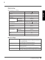
1
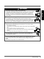
ENGLISH
®
SAFETY SYMBOLS
This manual uses the safety symbols below. They denote critical information. Please
read them carefully.
WARNING
Failure to abide by the information in a WARNING may result in serious
injury and can be life threatening.
CAUTION
Failure to abide by the information in a CAUTION may result in moderate
injury and/or property or product damage.
Indicates a prohibited action.
Indicates to ground for safety.
Copyright© 2000 by EIZO NANAO CORPORATION. All rights reserved. No part of
this manual may be reproduced, stored in a retrieval system, or transmitted, in any form
or by any means, electronic, mechanical, or otherwise, without the prior written
permission of Eizo Nanao Corporation.
Eizo Nanao Corporation is under no obligation to hold any submitted material or
information confidential unless prior arrangements are made pursuant to Eizo Nanao
Corporation's receipt of said information. Although every effort has been made to ensure
that this manual provides up-to-date information, please note that EIZO monitor
specifications are subject to change without notice.
ENERGY STAR is a U.S. registered mark.
Apple and Macintosh are registered trademarks of Apple Computer, Inc.
VGA is a registered trademark of International Business Machines Corporation.
DPMS is a trademark and VESA is a registered trademark of Video Electronics
Standards Association.
Windows is a registered trademark of Microsoft Corporation.
ScreenManager, PowerManager and i·Sound are trademarks of
Eizo Nanao Corporation.
FlexScan and EIZO are registered trademarks of Eizo Nanao Corporation.
As an ENERGY STAR® Partner, Eizo Nanao Corporation has determined that
this product meets the ENERGY STAR guidelines for energy efficiency.
2
TABLE OF CONTENTS
PRECAUTIONS .............................................................................. 4
1.
INTRODUCTION .......................................................................... 10
2.
ENGLISH
1-1. Features ..................................................................................................... 10
1-2. Package Contents ...................................................................................... 11
1-3. Controls & Connectors ................................................................................ 12
CABLE CONNECTION ................................................................ 14
2-1. Before connecting ....................................................................................... 14
2-2. Connecting up ............................................................................................. 15
3.
ScreenManager ........................................................................... 18
3-1. How to use the ScreenManager .................................................................. 18
3-2. ScreenManager Adjustments and Settings ............................................... 19
3-3. Useful Functions ......................................................................................... 20
4.
ADJUSTMENT ............................................................................ 22
4-1.
4-2.
4-3.
4-4.
Screen Adjustment ..................................................................................... 22
Displaying the low resolutions ..................................................................... 27
Color adjustment ......................................................................................... 29
Power-save Setup ....................................................................................... 31
5.
MAKING USE OF USB (Universal Serial Bus) .......................... 33
6.
CONNECTING TWO PCs to THE MONITOR ............................... 35
7.
ATTACHING AN ARM STAND .................................................... 37
8.
TROUBLE SHOOTING ................................................................ 39
9.
CLEANING ................................................................................... 43
10. SPECIFICATIONS ....................................................................... 44
11. GLOSSARY.................................................................................. 46
12. INDEX .......................................................................................... 48
APPENDIX ............................................................................................. i
TABLE OF CONTENTS
3
PRECAUTIONS
IMPORTANT
´ This product has been adjusted specifically for use in the region to which it was
originally shipped. If operated outside the region to which it was originally shipped,
the product may not perform as stated in the specifications.
´ To ensure personal safety and proper maintenance. Please read this section and the
caution statements on the unit (refer to the figure below).
[Location of the Caution Statements]
0.4A
(Shown only when removing the original stand)
WARNING
´ If the unit begins to emit smoke, smells like something is burning, or
makes strange noises, disconnect all power connections immediately and
contact your dealer for advice.
Attempting to use a malfunctioning unit can be dangerous.
´ Do not dismantle the cabinet or modify the unit.
Dismantling the cabinet or modifying the unit may result in electric shock or
burn.
´ Refer all servicing to qualified service personnel.
Do not attempt to service this product yourself as opening or removing covers
may expose you to dangerous voltage or other hazards.
4
PRECAUTIONS
WARNING
´ Place the unit on a strong, stable surface.
A unit placed on an inadequate surface may fall, resulting in injury or
equipment damage. If the unit falls, disconnect the power immediately and
have the unit checked by a qualified service engineer before using it again.
Using a unit after it has been dropped may result in fire or electric shock.
ENGLISH
• Keep small objects or liquids away from the unit.
Small objects accidentally falling through the ventilation slots into the cabinet
or spillage into the cabinet may result in fire, electric shock, or equipment
damage. If an object or liquid falls/spills into the cabinet, unplug the unit
immediately. Have the unit checked by a qualified service engineer before
using it again.
OK
´ Set the unit in an appropriate location.
Not doing so may cause damage and could result in fire or electric shock.
* Do not place in outdoors.
* Do not place in the transportation system (ship, aircraft, trains, automobiles,
etc.)
* Do not install in a dusty or humid environment.
* Do not place in a location where steam can have direct contact with the
screen.
* Do not place near heat generating devices or a humidifier.
• To avoid danger of suffocation, keep the plastic packing bags away
from babies and children.
• Use the enclosed power cord and connect to the standard power outlet of
your country. Be sure to remain within the rated voltage of the power
cord.
Not doing so may cause in fire or electric shock.
PRECAUTIONS
5
WARNING
´ To disconnect the power cord, grasp the plug firmly and pull.
OK
Never tug on the cord, doing so may cause damage and could result in fire or
electric shock.
´ The equipment must be connected to a grounded main outlet.
Failure to do this may reslut in an electric shock.
´ Use the correct voltage.
* The unit is designed for use with a specific voltage only. Connection to
another voltage than specified in this User’s Manual may cause fire, electric
shock, or other damage.
* Do not overload your power circuit, as this may result in fire or electric
shock.
* For proper connections of the power cord, be certain to plug the power cord
to the provided unit connector and directly to a wall outlet. Not doing so may
result in fire or electric shock.
´ Handle the power cord with care.
* Do not place the cord underneath the unit or other heavy objects.
* Do not pull on or tie the cord.
If the power cord becomes damaged, stop using it. Use of a damaged
cord may result in fire or electric shock.
´ Never touch the plug and power cord if it begins to thunder.
Touching them may result in electric shock.
´ When attaching an arm stand, please refer to the user’s manual of the arm
stand and install the unit securely with the enclosed screws.
Not doing so may cause the unit to come unattached, which may result in
injury or equipment damage. When the unit is dropped, please ask your dealer
for advice. Do not continue using a damaged unit. Using a damaged unit may
result in fire or electric shock. When reattaching the tilt stand, please use the
same screws and tighten them securely.
6
PRECAUTIONS
WARNING
WARNING
ENGLISH
´ Do not touch a damaged LCD panel directly with bare hands.
The liquid crystal which leaks from the panel is poisonous if it enters the eyes
or mouth. If any part of the skin or body comes in direct contact with the
panel, please wash thoroughly. If some physical symptoms result, please
consult your doctor.
´ Follow local regulation or laws for safe disposal.
The backlight of the LCD panel contains mercury.
CAUTION
´ Handle with care when carrying the unit.
Disconnect the power cord, cables and remove the optional i·Sound sound unit
(if applicable) when moving the unit. Moving the unit with the cord attached is
dangerous. It may result in injury or equipment damage.
* When handling the unit, grip the bottom of the unit firmly with both hands
ensuring the panel faces outward before lifting. Then, do not grasp the
LCD panel.
OK
Dropping the unit may result in injury or equipment damage.
´ Do not block the ventilation slots on the cabinet.
* Do not place books or any other papers on the ventilation slots.
* Do not install the unit in a closed space.
* Do not use the unit laying down or upside down.
Using the unit in these ways blocks the ventilation slots and prevents proper
airflow, leading to fire or other damage.
PRECAUTIONS
7
CAUTION
´ Do not touch the plug with wet hands.
Touching the plug with wet hands is dangerous and can cause electrical shock.
´ Use an easily accessible power outlet.
This will ensure that you can disconnect the power quickly in case of a
problem.
´ Periodically clean the area around the plug.
Buildup of dust, water, or oil on the plug may result in fire.
´ Unplug the unit before cleaning it.
Cleaning the unit while it is plugged into a power outlet may result in electric
shock.
´ If you plan to leave the unit unused for an extended period, disconnect the
power cord from the wall socket after turning off the power switch for the
safety and the power conservation.
8
PRECAUTIONS
Suggestions for Maximizing Comfort
´ To lessen the chance of possible injury and to increase your comfort and
productivity while you operate the unit, we suggest the followings:
ENGLISH
* Avoid less favorable body positioning. Sit back on the chair with
your back straight.
* Adjust the height of the chair so that the both soles touch the floor.
* Adjust the height of your chair, unit, or keyboard so that you can keep
your wrists straight while typing.
* Set the unit slightly below eye level.
´ Adjust brightness of the screen depending on the brightness of your
environment. Too dark or too bright of a screen can cause eye strain.
´ Be sure to take adequate rests. A 10-minute rest period each hour is
suggested.
LCD Panel
´ The screen may have defective pixels. These pixels may appear as
slightly light or dark area on the screen. This is due to the characteristics
of the panel itself, and not the product.
´ The backlight of the LCD panel has a fixed life span.
When the screen becomes dark or begins to flicker, please contact your
dealer.
´ Do not press on the panel or edge of the frame strongly, as this will result
in damage to the screen. There will be prints left on the screen if the
pressed image is dark or black. If pressure is repeatedly applied to the
screen, it may deteriorate or damage your LCD panel. Leave the screen
white to decrease the prints.
´ Do not scratch or press on the panel with any sharp objects, such as a
pencil or pen as this may result in damage to the panel. Do not attempt to
brush with tissues as this may scratch the LCD panel.
PRECAUTIONS
9
1. INTRODUCTION
Thank you very much for choosing an EIZO Color LCD Monitor.
1-1. Features
• DVI p.46) Digital input (TMDSp.47)) compliance (DVI-I x 2)
• 1280 x 1024 resolution
Horizontal scanning frequency of 27-82 kHz
Vertical scanning frequency of 50-85 Hz (1280 x 1024 ~75Hz)
Vertical (Digital) of 60Hz (VGA text: 70Hz)
• Auto Adjustment compliant and original “Picture Adjustment Program” software
included
• Smoothing function incorporated for the adjustment of an enlarged image
• ColorManagement function incorporated
• USB (Universal Serial Bus) hub supported
• The height adjustable stand incorporated
• Ultra slim bezel incorporated
• The Portrait/Landscape display capability
10
1. INTRODUCTION
1-2. Package Contents
• LCD Monitor
• Power Cord
• Signal Cable
(FD-C04)
• Signal Cable
(FD-C16)
• EIZO LCD Utility Disk
• User’s Manual
• Quick Reference
• Warranty Registration Card
• Please retain the packing materials for future transference.
1. INTRODUCTION
11
ENGLISH
Please contact your local dealer for assistance if any of the listed items are missing or
damaged.
1-3. Controls & Connectors
Front
(1)
(6)(7)
(8)
(1)
(2)
(3)
(4)
(5)
(6)
(7)
Main Power Switch
Input Signal Selection Button
Auto Adjustment Button
Enter Button
Control Buttons
Power Button
Power Indicator*1
Indicated color
Power-on status
Green
Power is on
Yellow
Power save mode
Flasing Yellow
Power save mode
Digital only
Slowly flashing Yellow Power is off (Main power is on)
(8)
ScreenManager™
*1
12
(2)(3)(4) (5)
Regarding the power indicator for the “Off Timer”, see page 21.
1. INTRODUCTION
Rear
ENGLISH
(10)
(11) (12) (13)
(14)
(15)
(9)
(9)
(10)
(11)
(12)
(13)
(14)
(15)
*2
*3
Height Adjustable Stand (Detachable) *2
DVI-I Input Connector x 2
Power Terminal Cover for the Optional Peripheral
USB Port (4 Downstream)
USB Port (1 Upstream)
Power Connector
Security Lock Slot*3
The LCD monitor has the capability of the Portrait/Landscape display.For the Portrait
display, use the software for the portrait.
The LCD monitor can be used with an optional arm stand by removing the stand
(see page 37).
Allows for connection of a security cable. This lock supports Kensington’s MicroSaver
security system. For further information, please consult:
Kensington Technology Group 2855 Campus Drive, San Mateo, CA 94403 USA
800-650-4242, x3348
Intl: 650-572-2700, x3348 / Fax: 650-572-9675
http://www.kensington.com
1. INTRODUCTION
13
2. CABLE CONNECTION
2-1. Before connecting
Before connecting your monitor to the PC, change the display screen settings (resolution
and frequency) in accordance with the charts below.
Analog Input
Resolution
640 x 480
640 x 480
720 x 400
800 x 600
832 x 624
1024 x 768
1152 x 864
1280 x 960
1280 x 1024
Frequency
~ 85 Hz
66.67 Hz
70 Hz
~ 85 Hz
75 Hz
~ 85 Hz
75 Hz
~ 85 Hz
~ 75 Hz
Remarks
VGA, VESA
Apple Macintosh
VGA Text
VESA
Apple Macintosh
VESA
VESA
Apple Macintosh
VESA
• About Plug & Play of the monitor
When your computer and display support VESA DDC, the suitable resolution
and the refresh rate are set by just plugging your display into the computer without
any manual settings. When your computer system supports Plug & Play, the
Display Information File is not required except for installing the Color Profile.
Digital Input
Only the following resolutions with frequency can be displayed on this model.
Resolution
640 x 480
720 x 400
800 x 600
1024 x 768
1280 x 960
1280 x 1024
14
2. CONNECTING UP
Frequency
60 Hz
70 Hz
60 Hz
60 Hz
60 Hz
60 Hz
Remarks
VGA
VGA Text
VESA
VESA
VESA
VESA
2-2. Connecting the signal cable
1.
Plug the signal cable into the DVI-I connector at the rear of the
monitor and the other end of the cable into the video connector on the
PC.
After connecting, secure the connection with the screw-in fasteners.
[Analog Input]
Connectors on rear
Video Output Connector
D-Sub mini 15 pin
·Standard graphics board
·Macintosh G3 (Blue & White) / G4
FD-C16 (enclosed)
Video Output Connector
D-Sub 15 pin
Macintosh
Macintosh Adapter (Optional)
[Digital Input]
Connectors on rear
Video Output Connector
DVI
Digital graphics board
FD-C04 (enclosed)
2. CONNECTING UP
15
ENGLISH
• Be sure that the power switches of both the PC and the monitor are OFF.
2.
Plug the power cord into the power connector on the rear of the
monitor.
WARNING
WARNING
• Use the enclosed power cord and connect to the standard
power outlet of your country. Be sure to remain within the
rated voltage of the power cord.
Not doing so may cause in fire or electric shock.
3.
Lead the power cord and signal cable into the cable holder at the rear
of the monitor.
• When housing the cables into the cable holder, lead them to the cable entrance
side and pinch the projection to open the cable entrance.
• The cables are recommended to lead with slight sag for the smooth motion of
the stand.
Projection
Cable Holder
16
2. CONNECTING UP
Cable Entrance
4.
Plug the other end of the power cord into a power outlet.
WARNING
WARNING
5.
ENGLISH
´ The equipment must be connected to a grounded main
outlet.
Not doing so may cause in fire or electric shock.
Turn on the monitor’s power and then switch on the PC’s power.
Whenever finished, turn off the PC and the monitor.
• When turning on the monitor, the kind of the input signal (Signal 1 or 2/Analog or
Digital) is displayed for a few seconds on the right top corner of the screen.
2. CONNECTING UP
17
3. ScreenManager
3-1. How to use the ScreenManager
As shown on the display, the ScreenManager is used to adjust the LCD monitor.
ScreenManager consists of main menus and sub menus. Adjustments are made using the
Enter and Control buttons (up, down, right and left) located on the front panel.
S IG N A L
1-2
AUTO
ENTER
Enter Button
Control Buttons
Auto Adjustment Button
1.
Entering the ScreenManager
Push the Enter button once to display the main menu of the ScreenManager.
[ Main Menu ]
2.
Making Adjustments and Settings
(1)
(2)
(3)
3.
Select the desired sub menu icon using the Control buttons and push the Enter
button. The sub menu appears.
Use the Control buttons to select the desired setting icon and push the Enter
button. The setting menu appears.
Use the Control buttons to make all required adjustments and push the Enter
button to save the settings.
Exiting the ScreenManager
(1)
To return to the main menu, select the “Return” icon or push the down button
twice, followed by the Enter button.
(2)
To exit the ScreenManager, select “Exit” icon and push the Enter button.
• Double clicking the Enter button at any time also exits the ScreenManager menu.
18
3. ScreenManager
3-2. ScreenManager Adjustments and Settings.
The following table shows all the ScreenManager’s adjustment and setting menus.
“*” indicates adjustments of analog input only and “**”indicates digital input only.
Input Priority
Beep
Menu Settings
Information
Language
Menu Size
ENGLISH
Main menu
Sub menu
Screen
Clock*
Phase*
Position
Resolution
Smoothing
Contrast/Brightness
Signal Filter*
ColorRange Adjustment*
Management Standard Mode
Temperature
Custom Mode
Temperature
Saturation
Hue
Gain
Save
PowerManager DVI DMPM**
VESA DPMS*
EIZO MPMS*
Others
Screen Size
Border Intensity
Off Timer
Reference
4. ADJUSTMENT(p.22)
Set the monitor’s off timer to
on or off. (p.21)
Select the priority signal. (p.36)
Set the Monitor’s beeper to on or
off. (p.45)
Change the size of the menu.
Menu Position Adjust the menu position.
Menu Off Timer Set the menu displaying time.
Translucent
Set the transparency of the
background.
Rotate
Change the orientation of the
ScreenManager.
Reset
Return to the factory default
settings. (p.45)
Information
Review the ScreenManager’s
settings, model name, Serial
Number and usage time*1.
English, German, French, Spanish, Select the ScreenManager’s
language.
Italian, Swedish and Japanese
*1 Due to the inspection on the factory, the usage time may not “0 hour” at purchasing.
3. ScreenManager
19
3-3.Useful Functions
Adjustment Lock
Use the “Adjustment Lock” function to prevent any accidental changes.
Locked function
Unlocked function
• Auto adjustment button adjustments and settings in the
ScreenManager.
• Adjustment of contrast and brightness by the control buttons.
• Input signal selection button
• To lock
Press on the Auto adjustment button while switching on the monitor’s power button
on the front panel.
• To unlock
Switch off the monitor’s power by the power button on the front panel, then hold
down the Auto adjustment button once again and turn the power back on.
EIZO Logo Disappearing function
When switching on the power button on the front panel, the EIZO logo is displayed for
a while. If you desire to undisplay this logo, use this function.
• To undisplay
Switch off the monitor’s power by the power button on the front panel. Turn the
power back again with pressing the enter button on the front panel.
• To display again
Switch off the monitor’s power by the power button on the front panel. Turn the
power back again with pressing the enter button on the front panel.
20
3. ScreenManager
Off Timer
[Procedure]
(1) Select “Off Timer” in the ScreenManager “Others” menu.
(2) Select “Enable” and press the right and left buttons to adjust the “On Period”
(1 to 23 hours).
[Off timer system]
PC
Monitor
LED
On Period (1H~23H)
Operation
Green
Last 15 min. in "On period"
Advance Notice *1
Green Flashing
"On period" expired
"Power Off" Mode
Flashing yellow slowly
*1
Advance notice (LED flashing green) will be given 15 minutes before the monitor
automatically enters the “Power Off” mode. To delay entering the “Power Off” mode,
press the power button during the advance notice period. The monitor will continue to
operate for an additional 90 minutes.
Press the power button to return to a normal screen.
• The off timer function works while the PowerManager is active, but there is no
advance notice before the monitor’s power is switched off.
3. ScreenManager
21
ENGLISH
The off timer function causes the monitor to automatically enter a power off state after a
predetermined amount of time has lapsed. This function was created to reduce
afterimage p.46) characteristics that are particular to LCD monitors when the monitor
screen is left on for a long period without use.
4. ADJUSTMENT
4-1. Screen Adjustment
• Allow the LCD monitor to stabilize for at least 20 minutes before making image
adjustments.
When connecting the DVI-I cable for digital input, please see page 26.
Adjustment Procedure for Analog Input
Screen adjustments for the LCD monitor should be used in suppressing screen flickering
and also for adjusting the screen to its proper position. There is only one correct position
for each display mode. It is also recommended to use the ScreenManager function when
first installing the display or whenever changing the system. For convenience, an easy
set-up Program installed on the utility disk to assist in the set-up procedure is provided.
1.
Push the Auto adjustment button on the front panel.
The message “Your setting will be lost, if you press again now.” appears and
remains on the screen for 5 seconds. While the message is on the screen, push the
Auto adjustment button again to automatically adjust the clock, phase, screen
position and resolution. If you do not wish to do adjust the screen, do not push the
Auto adjustment button again.
If the appropriate screen can not be made by using the Auto adjustment button,
adjust the screen through the following procedures.
2.
Install the “Screen adjustment program”.
Having read the “readme.txt” file, install and run the “Screen adjustment program”
in the enclosed EIZO LCD utility disk.
Step by step adjustment is provided by the wizard guide.
• If the user’s operating system has no utility disk (e.g. OS/2), we recommend
setting the desktop pattern to that as shown in the diagram below.
Every-other-dot
pattern
22
4. ADJUSTMENT
3.
Adjust by using “Screen” menu in the ScreenManager.
(1) Vertical bars appear on the screen.
Æ
Use the “Clock” p.46) adjustment
• When adjusting the “Clock,” the horizontal screen size will also change.
(2) Horizontal flickering, blurring or bars appear on the screen.
Æ
Use the “Phase” p.47) adjustment.
Select the “Phase” and eliminate the horizontal flickering, blurring or bars by
using the right and left buttons.
• Horizontal bars may not completely disappear from the screen depending on the
PC.
4. ADJUSTMENT
23
ENGLISH
Select the “Clock” and eliminate the vertical bars by using the right and left of
the control buttons. Do not continuously press the control buttons, as the
adjustment value will change quickly and make it difficult to locate the most
suitable adjustment point.
If the horizontal flickering, blur or bars appear, proceed to “Phase” adjustment
as follows.
(3) The screen position is incorrect.
Æ
Use the “Position” adjustment.
The correct displayed position of LCD monitor is decided because the number
and the position of the pixels are fixed. The “Position” adjustment moves the
image to the correct position.
Select “Position” and adjust the position of the upper left corner of the image
by using the up, down, right and left buttons in order to align the screen.
If vertical bars of distortion appear after finishing the “Position” adjustment,
return to “Clock” adjustment and repeat the previously explained adjustment
procedure (“Clock”Æ “Phase” Æ“Position”).
(4) Screen image is smaller or larger than the actual screen images.
Æ
Use the “Resolution” adjustment.
Adjustment is needed when the input signal resolution and the resolution now
being displayed is different.
Select “Resolution” and confirm if the resolution now being displayed is the
same as the input resolution. If it is not, adjust the vertical resolution using
the up and down button and adjust the horizontal resolution using the right
and left buttons.
Smaller than the actual screen images.
Adjusted to actual screen
Larger than the actual screen images.
24
4. ADJUSTMENT
4.
Set the Output signal range (Dynamic Range) of the signal.
Æ
Use the “Range Adjustment”.p.47)
[Auto]
Push the Auto adjustment button on the front panel while displaying the “Range
adjustment” menu to automatically adjust the range. The screen blanks for a
moment, and adjusts the color range to display the whole color gradation of the
current output signal.
• Pressing Auto adjustment button while displaying the contrast/brightness
adjustment screen (appeared by pressing the control buttons directly) adjusts the
range automatically.
5.
Set the Contrast of the screen.
Æ
Use the “Contrast” adjustment.
This controls the brightness for the each color (red, blue and green) at a same time.
Select “Contrast/Brightness” in the screen menu and adjust by using the right and
left buttons.
• Percentage over the 100 % may cause undisplayable color tone.
6.
Set the Brightness of the screen.
Æ
Use the “Brightness” adjustment.
This controls the brightness for the entire screen. The brightness of the entire screen
is controlled by changing the brightness if the backlight.
Select “Contrast/Brightness” in the screen menu and adjust by using the up and
down buttons.
• Directly pressing the control buttons also adjusts the contrast and brightness. Press
the “Enter” button to save and exit the settings after the adjustment.
4. ADJUSTMENT
25
ENGLISH
This controls the level of output signal range to display the whole color gradation
(256 colors). Select the “Range Adjustment”in the color menu.
Digital Input
The monitor displays the digital input image correctly based on its pre-setting data.
However, if the image position is not incorrect or larger than the actual image screen,
please adjust the following adjustment items using the “Screen” menu of the
ScreenManager.
1.
The screen position is incorrect.
Æ
Use the “Position” adjustment.
See page 24.
2.
Screen image is smaller or larger than the actual screen images.
Æ
Use the “Resolution” adjustment.
See page 24.
3.
Set the Contrast of the screen.
Æ
Use the “Contrast” adjustment.
See page 25.
4.
Set the Brightness of the screen.
Æ
Use the “Brightness” adjustment.
See page 25.
26
4. ADJUSTMENT
4-2. Displaying a low resolutions
1.
Enlarge the screen size when displaying a low resolution.
Select “Screen Size”
Select the “Screen Size” in the others menu and select the screen size by using the
up and down buttons.
• Full
• Enlarged
• Normal
Displays the picture on the screen in full, irrespective of the
picture’s resolution. Since the vertical resolution and the
horizontal resolution are enlarged at different rates, some
images may appear distorted.
Displays the picture on the screen in full, irrespective of the
picture’s resolution. Since the vertical resolution and horizontal
resolution are enlarged at same rates, some horizontal or
vertical image may disappear.
Displays the picture at the actual Screen resolution.
Example: Displaying 1024 x 768
Full
1280 x 1024
Enlarged
1280 x 960
Normal
1024 x 768
4. ADJUSTMENT
27
ENGLISH
Æ
2.
Smooth the blurred texts of the enlarged screen.
Æ
Use the “Smoothing” adjustment.
Select the suitable level from 1 ~ 5 (Soft ~ Sharp).
Select “Smoothing” in the screen menu and adjust by using the right and left
buttons.
• “Smoothing” is disabled when the screen is displayed in the following resolution.
* 1280 x 1024
* The image size is doubled both in horizontally and vertically (i.e. 1280 x 960
enlarged from 640 x 480) to provide clear focus which does not require this
function.
3.
Set the brightness of the black area surrounding the displayed image.
Æ
Set the “Border Intensity”
In the “Enlarged” mode or “Full Screen” mode, the outer area (border) is usually
black.
Select “Border Intensity” in the others menu and adjust by using the right and left
buttons.
Border
28
4. ADJUSTMENT
4-3. Color Adjustment
The “ColorManagement”menu in the ScreenManager enables to change the color of the
screen.
• Allow the LCD monitor to stabilize for at least 20 minutes before making color
adjustments.
• After finishing each adjustment in the custom mode, select “Save” icon to resister the
adjustment. Otherwise, the adjustment will be lost.
• The adjustment values represent the current level within the specific adjustment only.
They are available only as a reference tool. (To create a uniform white or black
screen, the percentages for each will probably not be the same.)
• In the analog input, perform the “Range Adjustment” (p.25) before making the color
adjustments . The gradation pattern like below is recommended for the “Range
Adjustment”.
1.
To change the color tone of the white.
Æ
Set the “Temperature”.p.46)
The “Temperature” can be set from 4,000 K to 10,000 K , in 500 K increments
(including 9,300 K). The default setting is “OFF”.
To resister the adjustment in the custom mode, select the “Save” icon and then push
the enter button.
• Setting the temperature under 4,000 K or over 10,000 K invalidates the color
temperature setting. (The color temperature’s setting turns “OFF”.)
• Adjusting the “Gain” (p. 30) invalidates the color temperature setting. (The
color temperature’s setting turns “OFF”.)
4. ADJUSTMENT
29
ENGLISH
Before the Color adjustment
2.
To change the saturation.
Æ
Use the “Saturation” adjustment.
The “Saturation” can be selected from -16 to 16. Setting the minimum level (-16)
turns the image to the monochrome.
To register the adjustment, select the “Save” icon and then push the enter button.
• The “Saturation” adjustment may cause undisplayable color tone.
3.
To change the flesh color, etc.
Æ
Use the “Hue” adjustment.
The “Hue” can be selected from -20 to 20.
To register the adjustment, select the “Save” icon and then push the enter button.
• The “Hue” adjustment may cause undisplayable color tone.
4.
To adjust each color (red, green and blue).
Æ
Use the “Gain”p.47) adjustment.
By adjusting the red, green and blue color tones for each mode, custom colors can
be defined.
The 100 % indicates unadjusted condition.
Display a white or gray background image and adjust the “Gain”.
To register the adjustment, select the “Save” icon and then push the Enter button.
• Adjusting the “Gain” invalidates the color temperature setting. (The color
temperature’s setting turns “OFF”. )
30
4. ADJUSTMENT
4-4. Power-save Setup
Analog Input
This monitor complies with the VESA DPMS p.47) standard and adopts a power saving
method, EIZO MPMS p.46), which works with a blank screen (totally black screen) like
“Blank Screen” ScreenSaver software.
1.
To use the PC’s power saving system (VESA DPMS ).
[Procedure]
(1) Set the PC’s power saving settings.
(2) Select “VESA DPMS” in the “PowerManager” menu.
[Power saving system]
PC
Monitor
LED
On
Operation
Green
Power saving
Yellow
Power saving mode
STAND-BY
SUSPEND
OFF
Operate the mouse or keyboard to return to a normal screen.
2. To set the power save with ScreenSaver software (EIZO MPMS).
[Procedure]
(1) Set the PC’s appropriate ScreenSaver settings or blank the screen (totally black
screen).
(2) Select “EIZO MPMS” from the “PowerManager” menu.
[Power saving system]
PC
Monitor
LED
ON
Operation
Green
Blank the screen
(ScreenSaver or
Macintosh Energy Saver)
Power saving
Yellow
Operate the mouse or keyboard to return to a normal screen.
4. ADJUSTMENT
31
ENGLISH
• Do your part to conserve energy, turn off the monitor when you are finished using it.
Disconnecting the monitor from the power supply is recommended to save energy
completely.
• Even if the monitor is in a power saving mode, USB compliant devices function when
they are connected to the monitor’s USB (both the upstream and the downstream
ports). Therefore, power consumption of the monitor will change according to the
connected devices even if the monitor is in a power saving mode.
• EIZO MPMS should be used with Macintosh “EnergySaver”.
Digital Input
This monitor complies with the DVI DMPM p.46).
[Procedure]
(1) Set the PC’s power saving settings.
(2) Select “DVI DMPM” in the “PowerManager” menu.
[Power saving system]
*1
PC
Monitor
LED
On
Operation
Green
Power saving
Power saving
Yellow
Off mode
Power saving*1
Flashing yellow
(2 times for each)
Power saving through the PC’s off mode is only supported when “Manual” is selected on
the ScreenManager’s “Input Priority”.
Operate the mouse or keyboard to return to a normal screen from the Power save mode
of the PC.
Power on the PC to return a normal screen from the Off mode of the PC.
32
4. ADJUSTMENT
5. MAKING USE OF USB
(Universal Serial Bus)
This monitor provides a hub which supports the USB standard. When connecting to a
USB compliant PC or another hub, the monitor functions as a hub to which the USB
compliant peripherals can be easily connected.
• PC equipped with USB ports or another USB hub connected to the USB compliant PC
• Windows 98/Me/2000 // Mac OS 8.5.1 or later
• USB cable / MD-C93 (Optional)
• The USB hub function may not work properly depending on the PC, OS or
peripherals. Please consult the manufacturer of each device about the USB support.
• When the monitor is not on, the peripherals connected to the downstream ports will
not operate.
• Even if the monitor is in a power saving mode, the devices connected to the
monitor’s USB ports (both the upstream and the downstream) will function.
Connecting to the USB HUB
• Do not connect the downstream port of the monitor to any peripherals until finishing
the USB function.
• The followings are procedures for the Windows 98/Me/2000 and Mac OS.
1.
Connect the monitor to the PC with the signal cable (See page 15) first, then turn on
the PC.
2.
Connect the upstream port of the monitor to the downstream port of the USB
compliant PC or another hub by using the USB cable .
Upstream
Ports
Upstream port:
Connect the USB
compliant PC or another
hub using the USB cable.
To Downstream Ports
of the PC or Another
Hub
After connecting the USB cable, the USB function can be set up automatically.
5. MAKING USE OF USB (Universal Serial Bus)
33
ENGLISH
Required system environment
3.
After setting up, the monitor’s USB hub is available for connecting USB compliant
peripherals to the downstream ports of the monitor.
Example of connection:
Scanner
Digital
Camera
Printer
USB
Cable
PC
Monitor
Keyboard
Mouse
Downstream
Scanner
Printer
Digital Camera Keyboard
34
5. MAKING USE OF USB (Universal Serial Bus)
Downstream ports:
Connect the cables from
USB compliant peripherals
such as a mouse, keyboard,
etc.
6. CONNECTING TWO PCs to
THE MONITOR
Two PCs can be connected to the monitor through the Signal 1 and the Signal 2 on the
back of the monitor.
Connecting Examples
• Analog x Digital
Video Output
Connector DVI
Digital graphics
board
ENGLISH
DVI-I connectors
Video Output Connector
D-Sub mini 15 pin
FD-C04
(enclosed)
FD-C16
(enclosed)
Standard graphics
board
• Analog x Analog
DVI-I connectors
Video Output
Connector
D-Sub mini 15 pin
·Macintosh G3
(Blue & White) / G4
• Digital x digital
Video Output Connector
D-Sub mini 15 pin
FD-C16
(Optional)
FD-C16
(enclosed)
DVI-I connectors
Video Output
Connector DVI
Video Output
Connector DVI
Digital graphics
board
Standard graphics
board
FD-C04
(Optional)
FD-C04
(enclosed)
Digital graphics
board
6. CONNECTING TWO PCs TO THE MONITOR
35
Selecting the active input
The Input signal selection button on the front
panel can be used to select either Signal 1 or
Signal 2 as the active input at any time. Every
time the button is pressed, the input changes.
When the switching the signal, the displaying
signal kind (signal 1 or 2/Analog or digital) is
displayed for a few seconds.
Input Signal
Selection Button
S IG N AL
1-2
A U TO
E N TE R
The priority input signal
This function is used to select which PC will have priority to control the monitor when
utilizing two PCs. The monitor constantly checks the input signals and switches
automatically in accordance with the “Input Priority” setting (see table below).
Once a priority is set, whenever a change of signal is detected at the selected input, the
monitor will switch the input to that signal.
In the case of only one signal being present at either input, the monitor automatically
detects and displays that signal.
Priority setting
Signal 1
Signal 2
Manual
Performance
If signals from both inputs are present, the monitor gives preference
to Signal 1 in the following cases.
• When the power of the monitor is turned ON
• When the signal input to Signal 1 is changed even if active input
was Signal 2.
If signals from both inputs are present, the monitor gives preference
to Signal 2 in the following cases.
• When the power of the monitor is turned ON
• When the signal input to Signal 2 is changed even if active input
was Signal 1.
The monitor will not detect signals automatically in this mode.
Select the active input by pressing the input signal selection button
on the monitor’s front panel.
• Regarding the power saving mode
When the Signal 1 or Signal 2 is selected, the power saving mode of the monitor
activates only if both PCs are in power saving mode.
36
6. CONNECTING TWO PCs TO THE MONITOR
7. ATTACHING AN ARM STAND
The LCD monitor can be used with an arm stand by removing the tilt stand and
attaching the arm stand to the LCD monitor.
NOTE
* Use an arm stand with a 100 mm x 100 mm hole
spacing on the arm mounting pad.
* Use an arm stand that is able to support an
object weighing 13.5 kg.
ENGLISH
´ Use an arm stand that satisfies the followings.
• When using the LCD monitor with an arm stand, the
arm stand must be VESA approved :
M4 x 16 mm x 4
100 mm
100 mm
´ TÜV/GS approved arm stand.
´ Use an arm stand with sufficient stability
(mechanical firmness) to support the weight of the
monitor.
´ Use an arm stand remaining that position where it is
manually moved.
´ Use an arm stand with the ability to tilt the monitor
forward and backward.
´ Please connect cables after attaching an arm stand.
Setup Procedure
1.
Lay the LCD monitor down. Do not scratch the panel.
2.
Remove the stand by loosening the screws. (4 pcs of M4 x 16 Ni/Fe)
7. ATTACHING AN ARN STAND
37
3.
Attach an arm stand to the LCD monitor securely.
WARNING
WARNING
´ When attaching an arm stand, please refer to the user’s manual
of the arm stand and install the unit securely with the enclosed
screws.
Not doing so may cause the unit to come unattached, which may
result in injury or equipment damage. When the unit is dropped,
please ask your dealer for advice. Do not continue using a
damaged unit. Using a damaged unit may result in fire or electric
shock. When reattaching the tilt stand, please use the same
screws and tighten them securely.
M4 Mounting Screws
:M4 x 16 (mm)
Arm-stand
For the Portrait display, rotate the monitor clockwise and use the software for the
portrait.
38
7. ATTACHING AN ARN STAND
8. TROUBLESHOOTING
Problems
1. No picture
• Indicator status: Off
• Indicator status: Green
• Indicator status: Yellow
• Indicator status:
Slowly flashing Yellow
2. Following messages
appear.
Points to check with possible solutions
Check that the power cord is correctly connected.
If the problem persists, turn off the monitor power for a
few minutes, then turn it back on and try again.
Check the “Contrast and Brightness” settings.
Minimum settings will cause screen to be blank.
Try pressing a key on the keyboard, or clicking the mouse.
(p.31)
Try pressing the power button.
These messages appear when the signal is not inputted
correctly, even if the monitor functions properly.
Error messages shown below will remain on the screen for
40 seconds.
When the image is displayed correctly after a short time,
there is no problem with the monitor.
(Some PCs do not output the signal soon after powering
on.)
Check that the PC is turned ON.
Check that the signal cable is properly connected to the PC
or graphics board.
Switch the signal input by pressing the input signal
selection button on the front control panel.
•Whenever an error signal
message appears, the
signal frequency will be
displayed in red.
(Example)
Use the graphics board’s utility software to change the
frequency setting. (Refer to the manual of the graphics
board.)
8. TROUBLESHOOTING
39
ENGLISH
If a problem persists even after applying the suggested remedies, contact an EIZO
dealer.
No picture problems Æ See No.1 ~ No.2
Imaging problems ÆSee No.3 ~ No.14
USB problemsÆSee No.19 ~ No.20
Other problemsÆSee No.15 ~ No.18
Problems
Points to check with possible solutions
3. Display position is
incorrect.
Adjust the image position using the “Position”.
(p.24)
If the problem persists, use the graphics board’s utility
software to change the display position if available.
4. Screen image is smaller or
larger than the actual
screen images.
Adjust the resolution using the “Resolution”. (p.24)
5. Vertical bars of distortion
appear.
Decrease the vertical bars using the “Clock”. (p.23)
6. Horizontal bars of
distortion appear.
Decrease the horizontal bars using the “Phase’. (p.23)
7. Letters and lines appear
blurred.
Adjust the blurred lines using “Smoothing”. (p.28)
8. Distortion appears like the
figure below.
This happens when both composite (X-OR) input signal
and separate vertical synchronizing signal are input.
Please select one of the two.
9. The screen is too bright or
too dark.
Adjust the “contrast and brightness”.
(The backlight of the LCD monitor has a fixed life span.
When the screen becomes dark or begins to flicker,
please contact your dealer.)
10.
When the screen image is changed after displaying the
same image for a long period, an afterimage may appear.
Use the “Off Timer” function and avoid keeping the screen
on all the time. (p.21)
40
Afterimages appear.
8. TROUBLESHOOTING
Problems
Points to check with possible solutions
This is due to the characteristics of the panel itself, and not
the LCD product.
12. Fingerprints remain on
the screen.
Leaving the screen black may solve the problem.
13. The “Smoothing” can not
be selected.
“Smoothing” is disabled when the screen is displayed in the
following resolution.
• 1280 x 1024
The image size is doubled both in horizontally and
vertically (i.e. 1280 x 960 enlarged from 640 x 480) to
provide clear focus which does not require this function.
14. The noise appears on the
screen.
Change the mode in “Signal Filter” in the “Screen”
Adjustment”.
15. The utility disk is unable
to be opened (for
Macintosh only).
Some Macintosh without PC-Exchange do not allow the
utility disk to be opened. Please set the desktop pattern to
every-other-dot before adjustment. (p.22)
16. • The Enter button does
not operate.
• The Auto adjustment
button does not operate.
The adjustment lock is probably on. To unlock: switch the
LCD monitor off. Then, while pressing the Auto
adjustment button switch, the power on. (p.20)
17. The Auto adjustment
button does not work
properly.
The Auto sizing function is intended for use on the
Macintosh and on AT-compatible PC running Windows.
It may not work properly in either of the following cases.
When running an AT-compatible PC on MS-DOS (Not
windows).
The background color for the “wall paper” or “desktop”
pattern is set to black.
Some signals from a graphics board may not function
properly.
8. TROUBLESHOOTING
41
ENGLISH
11. The screen has defective
pixels (e.g. slightly light
or dark).
Problems
Points to check with possible solutions
18. Frequency does not
change after installing
“Monitor information
file” in the attached
utility disk on Windows
95/98/Me/2000.
Use the graphics board’s utility software to change the
input signal frequency.
19. USB function cannot be
setup.
Check that the USB cable is correctly connected.
Check that the PC and OS are USB compliant.
(For verification of USB support, consult the manufacturer
of each system.)
Check the PC’s BIOS setting for USB.
(For details, refer to the manual of the PC.)
20. PC is hung up. / The
peripherals connected to
the downstream ports do
not operate.
Check that the USB cable is correctly connected.
Check the downstream ports by connecting the
peripherals to other downstream ports.
If the problem is solved by doing this, contact an EIZO
dealer.
Try executing the following method.
-Restarting the PC
-Connecting the PC and peripherals directly
If the problem is solved by doing this, contact an EIZO
dealer.
The power button of the APPLE keyboard does not
operate if it is connected to the EIZO USB Hub. Please
connect the keyboard directly with the PC. Refer to the
instruction of the PC for details.
42
8. TROUBLESHOOTING
9. CLEANING
Periodic cleaning is recommended to keep the monitor looking new and to prolong its
operation lifetime.
ENGLISH
• Never use thinner, benzene, alcohol (ethanol, methanol, or
isopropyl alcohol), abrasive cleaners, or other strong solvents,
as these may cause damage to the cabinet or LCD panel.
Cabinet
To remove stains, wipe the cabinet with a soft, lightly moistened cloth using a mild
detergent. Do not spray wax or cleaner directly onto the cabinet.
LCD Panel
The LCD surface can be cleaned with a soft cloth, such as cotton or lens paper.
If necessary, stubborn stains can be removed by moistening part of a cloth with water to
enhance its cleaning power.
9. CLEANING
43
10.SPECIFICATIONS
LCD Panel
Dot Pitch
Scan Frequency
Resolution
Dot Clock (Max.)
Display Colors
Display Area
Power Supply
Power Consumption
Input Connector
Input Signal
Signal registration
Plug & Play
Dimensions
Dimensions (without stand)
Adjustable Height
Weight
Weight (without stand)
Temperature
Humidity
USB specification
USB standard
Communication speed
Downstream power supply
USB ports
46 cm (18.1 inch), TFT color LCD panel with AntiGlare Hard Coating
Viewing Angle: Horizontal: 160º, Vertical: 160º
(at Contrast Ratio > 10)
Image Formation Time: approx. 78 ms
0.280 mm
Horizontal:
27 kHz - 82 kHz (Automatic)
Vertical:
50 Hz-85 Hz (Automatic)
(1280 x 1024: up to 75 Hz)
Vertical(Digital):
60Hz (VGA Text : 70Hz)
1280dots x 1024 lines
135 MHz
108 MHz(Digital)
16 milion colors (max)
359 mm (H) x 287 mm (V) (14.1” (H) x 11.3” (V))
(Viewable image size: 459 mm (18.1”))
100-120/200-240 VAC±10%, 50/60 Hz, 0.8 A/0.4 A
Normal/Max.: 56 W/76 W*
Power Saving Mode: Less than 5 W
(When the USB hub is not connected)
DVI-I x 2
Sync: a) Separate, TTL, Positive/Negative
b) Composite, TTL, Positive/Negative
c) Sync on Green, 0.3 Vp-p, Negative
Video: 0.7 Vp-p/75 Ω, Positive
(Digital: TMDS (Single Link))
28 (Factory preset: 23)(Digital: 5 (Factory preset: 0))
VESA DDC 2B
399 mm (W)x423.5 mm (H:minimum)x208.5 mm (D)
(15.7” (W) x 16.7” (H) x 8.2” (D))
399 mm (W) x 328 mm (H) x 65 mm (D)
(15.7” (W) x 12.9” (H) x 2.6”(D))
80mm (3.1”)
9.0 kg (19.8 lbs.)
5.5 kg (12.1 lbs.)
Operating:
0°C to 35°C (32°F to 95°F)
Storage:
-20°C to 60°C (-4°F to 140°F)
30% to 80% R.H. Non-condensing
Rev. 1.1 complied self-powered hub
12 Mbps (full), 1.5 Mbps (low)
500 mA for each (Max.)
Upstream port x 1, Downstream port x 2
* With EIZO optional speaker & USB attached.
44
10. SPECIFICATIONS
Default setting
Default setting are as follows:
ScreenManager menu
Analog
Digital
100%
Brightness
100%
Smoothing
3
ColorManagement
ENGLISH
Contrast
Color Mode
Standard
Temperature
Off
PowerManager
VESA DPMS
Screen Size
DVI DMPM
Full Screen
Input Priority
Signal 1
Off Timer
Disable
Menu Settings
Menu Size
Menu Off Timer
Beep
Language
Normal
45 seconds
On
English
Beeper settings
Short beep
Long beep
4 short beeps
2 short beeps every15 sec.
· ScreenManager item selected.
· ScreenManager parameter adjusted to minimum or
maximum limit.
· Input signal selection button pressed.
· Auto Adjustment button pressed.
· ScreenManager data-save executed.
· Monitor not connected correctly.
· PC turned off.
· Monitor received unsupported signal frequency.
· Monitor is in the advance notice mode of the Off
Timer. The power will be off within fifteen minutes.
10. SPECIFICATIONS
45
11.GLOSSARY
Afterimage
The Afterimage is particular to LCD monitors when the monitor screen is left on for
a long period without use. The “Afterimage” can be removed gradually by
changing the displayed image.
Clock
With the analog input signal display, the analog signal is converted to a digital
signal by the LCD circuitry. To convert the signal correctly, the LCD monitor needs
to produce the same number clock pulse as the dot clock of the graphics system.
When the clock pulse is not correctly set, some vertical bars of distortion are
displayed on the screen.
Color Temperature (Temperature)
Color Temperature is a method to measure the white color tone, generally indicated
in degrees Kelvin. At high temperatures the white tone appears somewhat blue,
while at lower temperatures it appears somewhat red. Computer monitors
generally give best perfoemance at high temerature settings.
5000K: Slightly reddish white.
6500K: Warm-white tone, similar to white papaer or daylight.
9,300K: Slightly bluish white.
DVI
(Digital Visual Interface)
A digital flat panel interface. DVI can transmit digital data from the PC directly
without loss with the signal transition method “TMDS”. There are two kinds of
DVI connectors. One is DVI-D connector for digital signal input only. The other is
DVI-I connector for both digital and analog signal inputs.
DVI-DMPM
(DVI Digital Monitor Power Management)
The Power management system for the digital interface. The “Monitor ON” status
(operation mode) and the “Active Off” status (power-saving mode) are indispensable
for the DVI-DMPM as the monitor’s power mode.
EIZO MPMS
EIZO MPMS, “EIZO Monitor PowerManager Signaling”, also enables power
saving on the monitor side. EIZO MPMS recognizes video signals from the PC
when the PC is in a power saving mode, and reduces energy consumption of the
monitor.
46
11. GLOSSARY
Gain Adjustment
Phase
The phase adjustment decides the sampling timing point for converting the analog
input signal to a digital signal. Adjusting the phase after the clock adjustment will
produce a clear screen.
Range Adjustment
The Range Adjustment controls the level of output signal range to display the whole
color gradation.
Resolution
The LCD panel consists of a fixed number of pixel elements which are illuminated
to form the screen image.
The EIZO L675 consists of 1280 horizontal pixels and 1024 vertical pixels. At a
resolution of 1280 X 1024, all pixels are used and the image is displayed as a full
screen. At the lower display modes of 640 x 480 or 800 x 600, the images are
displayed in the center of the screen using a smaller portion if the pixels.
TMDS
(Transition Minimized Differential Signaling)
A signal transition method for the digital interface.
VESA DPMS
The acronym VESA stands for “Video Electronics Standards
Association,” and DPMS stands for “Display Power Management Signaling.”
DPMS is a communication standard that PCs and graphics boards use to implement
power savings on the monitor side.
11. GLOSSARY
47
ENGLISH
Adjusts each color parameter for red, green and blue. The color of the LCD
monitor is displayed through the color filter of the LCD panel. Red, green and blue
are the three primary colors. The colors on the monitor are displayed by
combining these three colors. The color tone can change by adjusting the
illumination amount passed through each color’s filter.
12.INDEX
A
L
ADJUSTMENT --------------------------- 22
Adjustment Lock ------------------------- 20
Afterimage ----------------------------- 21,46
ATTACHING AN ARM STAND -------- 37
Language ---------------------------------- 19
M
MAKING USE OF USB
(Universal Serial Bus) --- 33
Menu Off Timer --------------------------- 19
Menu Position ----------------------------- 19
B
Beep ---------------------------------------- 19
Beeper setting ---------------------------- 45
Before connecting ----------------------- 14
Border Intensity --------------------- 19, 28
Brightness ------------------------ 19, 25,26
C
CABLE CONNECTION ----------------- 14
CLEANING -------------------------------- 43
Clock ------------------------------- 19, 23,46
Color Adjustment ------------------------- 29
ColorManagement ------------------ 19, 29
CONNECTING TWO PCs to
THE MONITOR -- 35
Contrast --------------------------- 19, 25,26
Controls & Connectors ------------------ 12
Custom Mode ----------------------------- 19
D
Default setting ---------------------------- 45
Dimensions --------------------------------- iv
Displaying the low resolutions -------- 27
DVI -------------------------------------- 10,46
DVI-DMPM ------------------------ 19,32,46
O
Off timer ------------------------------- 19, 21
Others -------------------------------------- 19
P
Package Contents ----------------------- 11
Phase ----------------------------- 19, 23, 47
Pin Assignment --------------------------- iv
Position ---------------------------- 19, 24,26
Power consumption --------------------- 44
Power Indicator --------------------------- 12
PowerManager ------------------- 19, 31,32
Power-save Setup ----------------------- 31
PRECAUTIONS --------------------------- 4
Preset Timing Chart ----------------------- i
R
Range Adjustment ------------------- 19,29
Reset --------------------------------------- 19
Resolution -------- 14,19, 24,26,40,44,47
Rotate -------------------------------------- 19
S
Saturation ----------------------------- 19, 30
Save ----------------------------------- 18, 19
Screen --------------------------------- 19, 23
Screen Adjustment ---------------------- 22
Screen Size -------------------------- 19, 27
ScreenManager --------------------------- 18
ScreenManager Adjustments
and Settings ----- 19
Security Lock Slot ----------------------- 13
Signal Filter --------------------------- 19, 41
Smoothing ---------------------------- 19, 28
SPECIFICATIONS ----------------------- 44
E
EIZO LCD utility disk -------------- 11, 22
EIZO Logo Disappearing function ---- 20
EIZO MPMS --------------------- 19, 31,46
G
Gain -------------------------------- 19, 30,46
GLOSSARY ------------------------------- 46
H
Height Adjustable Stand ----------- 10, 13
How to use the ScreenManager ------ 18
Hue ------------------------------------- 19, 30
I
Information -------------------------------- 19
Input Priority ------------------------- 19, 36
48
12. INDEX
T
Temperature ---------------------- 19, 29,47
TMDS ----------------------------------- 10,47
Translucent -------------------------------- 19
TROUBLE SHOOTING ----------------- 39
U
USB ----------------------------- 10,31,33,44
V
VESA DPMS ---------------------- 19,31,47
ENGLISH
12. INDEX
49
MEMO
50
12. INDEX
APPENDIX / ANHANG / ANNEXE
Preset Timing Chart for Analog input
Timing-Übersichten für Analog Eingang
Synchronisation des Signaux pour Analog numerique
Based on the signal diagram shown below 23 factory presets have been registered in
the monitor's microprocessor.
Der integrierte Mikroprozessor des Monitors unterstützt 23 werkseitige
Standardeinstellungen (siehe hierzu die nachfolgenden Diagramme).
23 signaux ont été enregistrés en usine dans le microprocesseur du moniteur,
conformément au diagramme de synchronisation ci-dessous.
A
Front Porch
Vordere Schwarzschulter
Front avant
B
Sync Period
Synchronimpuls
Délai de
synchronisation
C
Back Porch
Hintere Schwarzschulter
Front arrière
D
Blanking Period
Austastzeit
Délai de clignotement
E
Display period
Display-Zeit
Délai d'affichage
F
Total cycle
Kompletter Zyklus
Cycle total
H
Sync signal level
Sync-Signalpegel
Niveau du signal de
synchronisation
V
Video signal level
Video-Signalpegel
Niveau du signal vidéo
APPENDIX
APPENDIX
i
Mode
ii
APPENDIX
Dot Clock
Frequencies
A: Front Porch
B: Sync Period
H
µs/
Dot
V
ms/
Line
H
µs/
Dot
V
ms/
Line
59.941
0.636/
16
0.318/
10
3.813/
96
0.054/
2
31.468
70.087
0.636/
18
0.381/
12
3.813/
108
0.064/
2
30.24
35.00
66.67
2.116/
64
0.086/
3
2.116/
64
0.086/
3
Macintosh
832 x 624
57.28
49.73
74.55
0.559/
32
0.020/
1
1.117/
64
0.060/
3
Macintosh
1152 x 870
100.0
68.68
75.06
0.320/
32
0.044/
3
1.280/
128
0.044/
3
VESA
640 x 480
31.5
37.86
72.81
0.508/
24
0.026/
9
1.270/
40
0.079/
3
VESA
640 x 480
31.5
37.5
75.00
0.508/
16
0.027/
1
2.032/
67
0.080/
3
VESA
640 x 480
36.0
43.27
85.01
1.556/
56
0.023/
1
1.556/
56
0.069/
3
VESA
800 x 600
36.0
35.16
56.25
0.667/
24
0.028/
1
2.000/
72
0.057/
2
VESA
800 x 600
40.0
37.88
60.32
1.000/
40
0.026/
1
3.200/
128
0.106/
4
VESA
800 x 600
50.0
48.08
72.19
1.120/
56
0.770/
37
2.400/
120
0.125/
6
VESA
800 x 600
49.5
46.88
75.00
0.323/
16
0.021/
1
1.616/
80
0.064/
3
VESA
800 x 600
56.25
53.674
85.061
0.569/
32
0.019/
1
1.138/
64
0.056/
3
VESA
1024 x 768
65.0
48.36
60.00
0.369/
24
0.062/
3
2.092/
136
0.124/
6
VESA
1024 x 768
75.0
56.48
70.07
0.320/
24
0.053/
3
1.813/
136
0.106/
6
VESA
1024 x 768
78.75
60.02
75.03
0.203/
16
0.017/
1
1.219/
96
0.050/
3
VESA
1024 x 768
94.5
68.68
85.0
0.508/
48
0.015/
1
1.016/
96
0.044/
3
Workstation
1152 x 900
94.2
61.974
66.141
0.425/
40
0.032/
2
1.359/
128
0.065/
4
Workstation
1152 x 900 107.50
71.858
76.202
0.223/
24
0.028/
2
1.265/
136
0.111/
8
Macintosh
1280 x 960
126.2
74.763
74.763
0.190/
24
0.013/
1
1.204/
152
0.040/
3
VESA
1280 x 1024 108.0
63.98
60.02
0.444/
48
0.016/
1
1.037/
112
0.047/
3
Workstation
1280 x 1024 117.0
71.691
67.189
0.205/
24
0.028/
2
0.957/
112
0.112/
8
VESA
1280 x 1024 135.0
79.97
75.02
0.119/
16
0.013/
1
1.067/
144
0.038/
3
MHz
H
kHz
V
Hz
VGA
640 x 480
25.175
31.468
VGA
720 x 400
28.322
Macintosh
640 x 480
C: Back Porch
D: Blanking Period
E:Display Period
F:Total Cycle
V
ms/
Line
H
µs/
Dot
V
ms/
Line
H
µs/
Dot
V
ms/
Line
H
µs/
Dot
V
ms/
Line
1.907/
48
1.048/
33
6.356/
160
1.430/
45
25.442/
640
15.254/
480
31.778/
800
16.683/
525
1.907/
54
1.111/
35
6.356/
180
1.556/
49
25.422/
720
12.712/
400
31.778/
900
14.267/
449
3.175/
96
1.114/
39
7.407/
224
1.286/
45
21.164/
640
13.714/
480
28.571/
864
15.000/
525
3.911/
224
0.784/
39
5.586/
320
0.865/
43
14.524/
832
12.549/
624
20.111/
1152
13.414/
667
1.440/
144
0.568/
39
3.040/
304
0.655/
45
11.520/
1152
12.667/
870
14.560/
1456
13.322/
915
3.810/
128
0.528/
28
5.587/
192
0.634/
40
20.317/
640
12.678/
480
26.413/
832
13.735/
520
3.810/
120
0.427/
16
6.349/
200
0.533/
20
20.317/
640
12.800/
480
26.667/
840
13.333/
500
2.222/
80
0.578/
25
5.333/
192
0.670/
29
17.778/
640
11.093/
480
23.111/
832
11.764/
509
3.556/
128
0.626/
22
6.222/
224
0.711/
25
22.222/
800
17.067/
600
28.444/
1024
17.778/
625
2.200/
88
0.607/
23
6.400/
256
0.739/
28
20.000/
800
15.840/
600
26.400/
1056
16.579/
628
1.280/
64
0.478/
23
4.800/
240
1.373/
66
16.000/
800
12.480/
600
20.800/
1040
13.853/
666
3.232/
160
0.448/
21
5.172/
256
0.533/
25
16.162/
800
12.800/
600
21.333/
1056
13.333/
625
2.702/
152
0.503/
27
4.409/
248
0.578/
31
14.222/
800
11.179/
600
18.631/
1048
11.756/
631
2.462/
160
0.600/
29
4.923/
320
0.786/
38
15.754/
1024
15.880/
768
20.677/
1344
16.666/
806
19.20/
144
0.513/
29
4.053/
304
0.673/
38
13.653/
1024
16.599/
768
17.707/
1328
14.272/
806
2.235/
176
0.466/
28
3.657/
288
0.533/
32
13.003/
1024
12.795/
768
16.660/
1312
13.328/
800
2.201/
208
0.524/
36
3.725/
352
0.582/
40
10.836/
1024
11.183/
768
14.561/
1376
11.765/
808
2.123/
200
0.500/
31
3.907/
368
0.597/
37
12.229/
1152
14.522/
900
16.136/
1520
15.119/
937
1.712/
184
0.459/
33
3.200/
344
0.598/
43
10.716/
1152
12.525/
900
13.916/
1496
13.123/
943
1.838/
232
0.482/
36
3.233/
408
0.535/
40
10.143/
1280
12.841/
960
13.376/
1688
13./376
1000
2.296/
248
0.594/
38
3.778/
408
0.656/
42
11.852/
1280
16.005
1024
15.630/
1688
16.661/
1066
1.846/
216
0.460/
33
3.009/
352
0.600/
43
10.940/
1280
14.283/
1024
13.949/
1632
14.883/
1067
1.837/
248
0.475/
38
3.022/
408
0.525/
42
9.481/
1280
12.804/
1024
12.504/
1688
13.329/
1066
APPENDIX
H
µs/
Dot
APPENDIX
iii
Dimensions
Abmessungen
Dimensions
399 (15 .7 )
361 (14 .2 )
R an
ge o
fM
o ti o
mm
(inches)
n: 4
0
65(2.6)
39(1.5)
289 .2(11.4)
328 (12 .9 )
3(0.1)
80(3.1):A djustable He ight
3(0.1)
288 .5(11.4)
M a in SW
3(0.1)
259 .5(10 .2)
95.5(3.8)
503 .5(20 .0)
3(0.1)
R an ge of M otion
38(1.5)
325 .5(12 .8)
208 .5(8.2)
FRONT VIEW
VORDERANSICHT
VUE DE FACE
TOP VIEW
DRAUFSICHT
VUE D'EN HAUT
SIDE VIEW
SEITENANSICHT
VUE DE COTE
Pin Assignment
Pin-Belegung
Affectation des Broches
* DVI-I Connector
1
2
3
4
5
6
7
8
Pin
No.
C1
C2
C3
C4
C5
Signal
TMDS Data2-
2
TMDS Data2+ 12
TMDS Data2/4
13
Shield
4
NC*
14
3
5
NC
Signal
Pin
No.
TMDS Data1/3
11
21
Shield
1
9 10 11 12 13 14 15 16
17 18 19 20 21 22 23 24
Pin
No.
Signal
NC
TMDS Clock
Shield
NC
22
NC
23 TMDS Clock+
+5V Power
24 TMDS ClockGround (return
15 for +5V, Hsync C1 Analog Red
and Vsync)
DDC Clock
16 Hot Plug Detect C2 Analog Green
(SCL)
7 DDC Data (SDA) 17 TMDS Data0- C3 Analog Blue
Analog
Analog
8
18 TMDS Data0+ C4
Horizontal Sync
Vertical Sync
Analog Ground
TMDS Data0/5
9 TMDS Data1- 19
C5 (analog R,G,&B
Sheild
return)
10 TMDS Data1+ 20
NC
6
(*NC: No Connection)
* USB ports
Upstream
(Series B connector)
iv
APPENDIX
Downstream
(Series A connector)
No.
Signal
Comments
1
VCC
Cable power
2
- Data
Serial data
3
+ Data
Serial data
4
Ground
Cable Ground
[Applicable to gray (standard color version only).]
Congratulations!
You have just purchased a TCO’99 approved and labelled
product! Your choice has provided you with a product developed
for professional use. Your purchase has also contributed to
reducing the burden on the environment and also to the further
development of environmentally adapted electronics products.
Why do we have environmentally labelled computers?
In many countries, environmental labelling has become an established method for
encouraging the adaptation of goods and services to the environment. The main problem, as
far as computers and other electronics equipment are concerned, is that environmentally
harmful substances are used both in the products and during their manufacture. Since it is not
so far possible to satisfactorily recycle the majority of electronics equipment, most of these
potentially damaging substances sooner or later enter nature.
There are also other characteristics of a computer, such as energy consumption levels, that
are important from the viewpoints of both the work (internal) and natural (external)
environments. Since all methods of electricity generation have a negative effect on the
environment (e.g. acidic and climate-influencing emissions, radioactive waste), it is vital to
save energy. Electronics equipment in offices is often left running continuously and thereby
consumes a lot of energy.
What does labelling involve?
This product meets the requirements for the TCO’99 scheme which provides for
international and environmental labelling of personal computers. The labelling scheme was
developed as a joint effort by the TCO (The Swedish Confederation of Professional
Employees), Svenska Naturskyddsforeningen (The Swedish Society for Nature Conservation)
and Statens Energimyndighet (The Swedish National Energy Administration).
Approval requirements cover a wide range of issues: environment, ergonomics, usability,
emission of electric and magnetic fields, energy consumption and electrical and fire safety.
The environmental demands impose restrictions on the presence and use of heavy metals,
brominated and chlorinated flame retardants, CFCs (freons) and chlorinated solvents, among
other things. The product must be prepared for recycling and the manufacturer is obliged to
have an environmental policy which must be adhered to in each country where the company
implements its operational policy.
The energy requirements include a demand that the computer and/or display, after a
certain period of inactivity, shall reduce its power consumption to a lower level in one or
more stages. The length of time to reactivate the computer shall be reasonable for the user.
Labelled products must meet strict environmental demands, for example, in respect of the
reduction of electric and magnetic fields, physical and visual ergonomics and good usability.
Below you will find a brief summary of the environmental requirements met by this
product.
The complete environmental criteria document may be ordered from:
TCO Development
SE-114 94 Stockholm, Sweden
Fax: +46 8 782 92 07
Email (Internet): [email protected]
Current information regarding TCO’99 approved and labelled products may also be
obtained via the Internet, using the address: http://www.tco-info.com/
[Applicable to gray (standard color version only).]
Environmental requirements
Flame retardants
Flame retardants are present in printed circuit boards, cables, wires, casings and
housings. Their purpose is to prevent, or at least to delay the spread of fire. Up to 30% of
the plastic in a computer casing can consist of flame retardant substances. Most flame
retardants contain bromine or chloride, and those flame retardants are chemically related to
another group of environmental toxins, PCBs. Both the flame retardants containing bromine
or chloride and the PCBs are suspected of giving rise to severe health effects, including
reproductive damage in fish-eating birds and mammals, due to the bio-accumulative*
processes. Flame retardants have been found in human blood and researchers fear that
disturbances in foetus development may occur.
The relevant TCO’99 demand requires that plastic components weighing more than 25
grams must not contain flame retardants with organically bound bromine or chlorine. Flame
retardants are allowed in the printed circuit boards since no substitutes are available.
Cadmium**
Cadmium is present in rechargeable batteries and in the colour-generating layers of
certain computer displays. Cadmium damages the nervous system and is toxic in high doses.
The relevant TCO’99 requirement states that batteries, the colour-generating layers of
display screens and the electrical or electronics components must not contain any cadmium.
Mercury**
Mercury is sometimes found in batteries, relays and switches. It damages the nervous
system and is toxic in high doses. The relevant TCO’99 requirement states that batteries
may not contain any mercury. It also demands that mercury is not present in any of the
electrical or electronics components associated with the labelled unit.
CFCs (freons)
The relevant TCO’99 requirement states that neither CFCs nor HCFCs may be used during
the manufacture and assembly of the product. CFCs (freons) are sometimes used for washing
printed circuit boards. CFCs break down ozone and thereby damage the ozone layer in the
stratosphere, causing increased reception on earth of ultraviolet light with e.g. increased
risks of skin cancer (malignant melanoma) as a consequence.
Lead**
Lead can be found in picture tubes, display screens, solders and capacitors. Lead damages
the nervous system and in higher doses, causes lead poisoning. The relevant TCO’99
requirement permits the inclusion of lead since no replacement has yet been developed.
* Bio-accumulative is defined as substances which accumulate within living organisms.
** Lead, Cadmium and Mercury are heavy metals which are Bio-accumulative.
For U.S.A, Canada, etc. (rated 100-120 Vac) Only
FCC Declaration of Conformity
We, the Responsible Party
EIZO NANAO TECHNOLOGIES INC.
5710 Warland Drive, Cypress, CA 90630
Phone: 562 431 5011
declare that the product
Trade name: EIZO
Model: FlexScan L675
is in conf
or
mity with P
ar
ation of this pr
oduct is subject to the
confor
ormity
Par
artt 15 of the FCC Rules. Oper
Opera
product
follo
wing tw
o conditions: (1) this de
vice ma
y not cause har
mful interf
er
ence
ollowing
two
device
may
harmful
interfer
erence
ence,, and (2) this
er
ence tha
y cause
ence rrecei
ecei
ved
luding interf
de
vice m
ust acce
pt an
y interf
er
may
ed,, inc
including
interfer
erence
thatt ma
accept
any
interfer
erence
eceiv
device
must
ation.
undesir
ed oper
undesired
opera
This equipment has been tested and found to comply with the limits for a Class B digital
device, pursuant to Part 15 of the FCC Rules. These limits are designed to provid
reasonable protection against harmful interference in a residential installation. This
equipment generates, uses, and can radiate radio frequency energy and, if not installed
and used in accordance with the instructions, may cause harmful interference to radio
communications. However, there is no guarantee that interference will not occur in a
particular installation. If this equipment does cause harmful interference to radio or
television reception, which can be determined by turning the equipment off and on, the
user is encouraged to try to correct the interference by one or more of the following
measures.
*Reorient or relocate the receiving antenna.
*Increase the separation between the equipment and receiver.
*Connect the equipment into an outlet on a circuit different from that to which the
receiver is connected.
*Consult the dealer or an experienced radio/TV technician for help.
Changes or modifications not expressly approved by the party responsible for
compliance could void the user’s authority to operate the equipment.
Note
Use the attached specified cable below or EIZO signal cable with this monitor so as to
keep interference within the limits of a Class B digital device.
-AC Cord
-Shielded Signal Cable (enclosed)
Canadian Notice
This Class B digital apparatus complies with Canadian ICES-003.
Cet appareil numérique de le classe B est comforme à la norme NMB-003 du Canada.