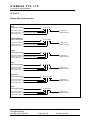
1
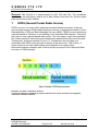
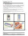
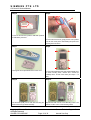
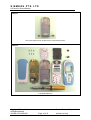
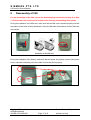
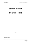
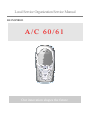
Local Service Organization Service Manual
BE INSPIRED
A/C 60/61
Our innovation shapes the future
SIEMENS PTE LTD
C60 Level 2 Service Manual
Table of Contents
1
GPRS (GENERAL PACKET RADIO SERVICE)……….3
2
K JAVA APPLICATION……………………………………………………………….4
3
KEY FEATURES……………………………………………………………………….5
4
COMPARISON WITH PERVIOUS PRODUCT...……………………………………7
5
ACCESSORIES……………………………………………………………………......8
6
UNIT DESCRIPTION C60 ...………..……………………………………………….10
7
DISASSEMBLYOF C60........………………………………………………………..14
8
REASSEMBLY OF C60……………………………………………………………...17
9
MOBILE SOFTWARE PROGRAMMING…………………………………………..18
10
SIEMENS SERVICE EQUIPMENT USER MANUAL……………………………..21
11
JPICS INTERNET……………………………………………………………………22
12
INTERNATIONAL MOBILE EQUIPMENT IDENTITY, IMEI……………………..28
13
GENERAL TESTING INFORMATION……………………………………………..29
Annex 1……………………………………………………………………………………….34
Annex 2……………………………………………………………………………………….35
Copyright © Siemens Pte Ltd.
All Rights Reserved
ICM MP CCQ ASP/ASC
Siemens Technical Support Centre
Page 2 of 35
Internal Use Only
SIEMENS PTE LTD
C60 Level 2 Service Manual
General: This manual is a combi-manual for A60, C60 and C61. The procedures
described in this manual are valid for all of them. Basis is here the C60. All other spare
parts can be find in the C-Market
1
GPRS (General Packet Radio Service)
GPRS is a new non-voice value added services that allows information to be sent
and received across a GSM mobile telephone network. It supplements today’s Circuit
Switched Data (CSD) and Short Message Services (SMS). GPRS involves overlaying
a packet based air interface on the existing circuit switched GSM network. This gives
the option to use a packet-based data service. The information is split into separated
but related “packets” before being transmitted and reassembled at the receiving end.
Theoretically, maximum speeds of up to 171.2 kilobits per second (kbps) are
achievable with GPRS using all eight timeslots at the same time. This is about 3
times as fast as the data transmission speed possible over today’s fixed
telecommunications networks and 10 times as fast as current Circuit Switched Data
services on GSM networks.
Example: Cell with 1 Frequency channel:
1 physical channel for signaling, 4 physical channels for Circuit switched and 3 physical
channels for Packet switched.
Copyright © Siemens Pte Ltd.
All Rights Reserved
ICM MP CCQ ASP/ASC
Siemens Technical Support Centre
Page 3 of 35
Internal Use Only
SIEMENS PTE LTD
C60 Level 2 Service Manual
2
K-Java Application
Java-based game system
Java Application Manager
(JAM)
Application
launcher
download manager.
and
yes
Supports HTTP-based OTA
download of applications over
GPRS and CSD.
RAM for Java applications
Available RAM for Java
applications (i.e. Program code
and data) during application
runtime:
yes
Minimum 100 Kbytes (Has to be
taken as working assumption
for application development).
Goal: 145 Kbytes as SL45i (not
committed)
MIDP 1.0, CLDC 1.0
As
SL45i,
including
performance optimizations from
SL45i-Infusio.
yes
‘OEM extensions’
Proprietary API extension as
SL45i.
Including
‘Siemens
Game API’
yes
Sl45i: only CSD
yes
HTTP API over GPRS
Copyright © Siemens Pte Ltd.
All Rights Reserved
ICM MP CCQ ASP/ASC
Siemens Technical Support Centre
Page 4 of 35
Internal Use Only
SIEMENS PTE LTD
C60 Level 2 Service Manual
3
Key Features
•
•
•
•
•
•
•
•
Bands
Battery
Stand-by Time
Talk Time
Triple Band E-GSM 900 / GSM 1800 / GSM 1900
GPRS Multi Class 8
Li-Ion Battery Pack
Nominal Voltage : 3.7V
Nominal Capacity : 750 mAh
GSM Capacity
: 700 mAh
Power Input
: 1.8A (0.6 ms) / (4 ms)
Cut-off Threshold : 3.2V
• Approx. 250 h / Li-Ion (measured at BSPAMFRMS = 9;
Number of neighboring cells = 0)
• Best case approx.
5 hours (lowest output level with
DTX
• Worst case approx. : 2.0 hours (highest output level with
DTX)
Condition for DTX : 40% user talk time
SIM Card
•
•
Small (”Plug In”) 3V SIM card (Phase II)
To insert the SIM card, the battery pack must be
removed.
GSM Antenna
•
A triple band PIFA antenna will be an integral part of the
mobile phone.
Receiver Sensitivity
•
EGSM: -102 dBm (-104dBm-15.2) (Specification; static
& with fading)
PCN : -102 dBm (Specification; static & with fading)
•
The reception sensitivity must comply with the corresponding
GSM recommendations in all operating conditions
(temperature,
battery level ...).
•
•
EGSM: measurements according typical sensitivity are
not yet available.
PCN: measurements according typical sensitivity are
not yet available
Measurement values are referred to the external antenna
connector.
Transmitter Power
Copyright © Siemens Pte Ltd.
All Rights Reserved
ICM MP CCQ ASP/ASC
•
EGSM: nominal 2W (Specification: Class 4 Mobile
Siemens Technical Support Centre
Page 5 of 35
Internal Use Only
SIEMENS PTE LTD
C60 Level 2 Service Manual
•
phone)
PCN: nominal 1W (Specification: Class 1 Mobile phone)
Transmitter output characteristics is according to GSM 11.10
specification implying all specified operating conditions
(temperature, battery level ...).
Transmitter set points will be specified for GSM and PCN when
typical values and statistical values become available.
Speech Codec
•
Triple Rate (HR/FR/EFR) and AMR
Temperature
Range
•
•
-100C to +550C (Normal operation)
-300C to +850C (Storage capability)
Display
•
•
•
•
•
•
•
•
Type: Full Graphic
Resolution: 101 x 80 Pixel
Color depth: 4096
Technology: Color STN
Active area / mm: 29.379 x 25.265
Visible area / mm: max. 32.4 x 28.9
Illumination: White LED
Contrast: Adjustable
Keypad
•
•
•
•
•
Partially bridgeless
12-digit block (0-9, #, *) and two function keys (SEND,
END) in one block with small letters.
ON/OFF key combined with the END key; the symbol _
(I inside O) is used as a symbol for ON/OFF.
2 soft keys
4-way navigation key
Illumination color : Amber
Acoustics
•
•
Comfortable earpiece
Omni-directional microphone
Internet Access
Camera
•
•
•
Wap 1.2.1
Attachable camera with integrated flash
Sensor with VGA resolution: Choice of two resolutions:160 x 120 pixels and 640 x 480 pixels
Photo can be viewed on the mobile’s display
•
•
Copyright © Siemens Pte Ltd.
All Rights Reserved
ICM MP CCQ ASP/ASC
Siemens Technical Support Centre
Page 6 of 35
Internal Use Only
SIEMENS PTE LTD
C60 Level 2 Service Manual
4
Comparison with Previous Product
Feature
Supported Systems
MC60
C60
Triple Band – EGSM 900 / Triple Band – EGSM 900 /
1800 / 1900
1800 / 1900
Stand-by Time
Up to 250 H
Up to 250 H
Talk Time
Up to 5 H
Up to 5 H
Battery Type / Capacity
Li-Ion Battery Pack
Li-Ion Battery Pack
Nominal Cap. : 700 mAh
Nominal Cap.: 700 mAh
Weight
Approx. 86 g
Approx. 85 g
Volume
Approx. 88 cm3
Approx. 91 cm3
Length
109 mm
110 mm
Width
46 mm
47 mm
Thickness
21 mm
23 mm
SIM
Plug-in 3 V
Plug-in 3 V
Antenna
Integrated
Integrated
SAR related to 1 g
1.0 W/kg @ 900 MHz
2.0 W/kg @ 900 MHz
0.8 W/kg @ 1800 MHz
0.8 W/kg @ 1800 MHz
0.8 W/kg @ 1900 MHz
0.8 W/kg @ 1900 MHz
Full Rate
Yes
Yes
Half Rate
Yes
Yes
Enhanced Full Rate
Yes
Yes
AMR
Yes
Yes
Fax / Data
Yes
Yes
GPRS
Yes, Class 8
Yes, Class 8
Keypad Illumination
Yes
Yes
Display
4K color STN full dot matrix, 4K color STN full dot matrix,
6 lines graphic + icons
6 lines graphic + icons
Display Illumination
White
White
Ringer Volume Level
Min. 95 dB(A) @ 5 cm
Min. 95 dB(A) @ 5 cm
Typ. > 100 dB(A) @ 5 cm
Typ. > 100 dB(A) @ 5 cm
Copyright © Siemens Pte Ltd.
All Rights Reserved
ICM MP CCQ ASP/ASC
Siemens Technical Support Centre
Page 7 of 35
Internal Use Only
SIEMENS PTE LTD
C60 Level 2 Service Manual
5
Accessories
For C60, the following accessories will be available.
Description
Part number
Li-Ion Battery EBA-510
L36880-N5601-A100
Car Charger ECC-500
L36880-N5601-A106
Travel Charger (Euro) ETC-500
L36880-N5601-A104
Travel Charger (UK) ETC-510
L36880-N5601-A105
Desk Top Charger EDC-510
L36880-N5601-A101
Headset with PTT HHS-510
L36880-N5601-A108
Basic Car Pack (Headset, Car Charger, Y-Adapter) HKB-500
L36880-N5601-A118
Car Kit Portable HKP-500
L36880-N5601-A109
Car Kit Comfort HKC-540
L36880-N5701-A100
Car Data Adapter (for CK Prof. Voice II) HKO-530
L36880-N5701-A108
Car Kit Professional Voice II (E) HKV-570
L36880-N5601-A100
Push To Talk Key (for CK Prof. Voice II) HKO-520
L36880-N4501-A135
Sync Station DSC-500
L36880-N5601-A103
Data Link Cable USB DCA-510
L36880-N5601-A111
Tour Case FCT-550
L36880-N5601-A140
Hands-free Loudspeaker
L36104-F3090-X903
Base Module without key with Slim-Lumberg-Connector
L36158-A91-A10
Hands-free Microphone Active
L36254-Z6-C95
E-Box Car Kit Voice
L36880-S4501-A301
Serial Data Cable
L36880-S5601-A800
QuickPic Camera IQP-500
L36880-S5701-A410
Copyright © Siemens Pte Ltd.
All Rights Reserved
ICM MP CCQ ASP/ASC
Siemens Technical Support Centre
Page 8 of 35
Internal Use Only
SIEMENS PTE LTD
C60 Level 2 Service Manual
5.1 C60 Interface to accessories
The phone has a fully compatible interface to accessories. The connectors (I/O and RF)
are identical to the L55 Family (C55, S55, A55/52, SL55, M55, and MC60).
Mechanical interfaces are defined on the mobile phone to make sure that the accessories
are compatible across the whole L55 platform.
Slim Lumberg I/O Connector
Copyright © Siemens Pte Ltd.
All Rights Reserved
ICM MP CCQ ASP/ASC
Siemens Technical Support Centre
Page 9 of 35
Internal Use Only
SIEMENS PTE LTD
C60 Level 2 Service Manual
6
Unit Description of C60
C60 is part of the L55 platform with the following specific features:
•
•
•
Integrated tri-band antenna
Colour Display
Exchangeable Housings
The concept of the device is optimized regarding design-to-cost and easy-to-assemble.
The phone consists of an inner unit and exchangeable housings,
whereby the inner unit consist mainly of three components or assemblies:
•
•
•
PCB assembled
Light guide assembled
Mounting frame assembled
The PCB is based on the C55 Platform. All electro-mechanic components are taken from
C55, except the Display, which is used in M55. The RF chamber and shielding is the
same as in MC60. The Mounting Frame is similar to the MC60 part but without holes for
camera and external antenna connector. Each of the preassemblies, upper part,
mounting frame, and light guide module are designed to be automatically mounted and
checked. These preassemblies are designed to be easily assembled.
Copyright © Siemens Pte Ltd.
All Rights Reserved
ICM MP CCQ ASP/ASC
Siemens Technical Support Centre
Page 10 of 35
Internal Use Only
SIEMENS PTE LTD
C60 Level 2 Service Manual
6.1
Exploded View of C60
Display Lens
Upper Case Assembly
Keypad
Screws
Speaker Cushion
Light guide assembly
Display Module
Mounted PCB
SIM Slider
Antenna
Vibra Motor
Mounting Frame Assembly
Microphone
Battery Pack
Lower Case
Copyright © Siemens Pte Ltd.
All Rights Reserved
ICM MP CCQ ASP/ASC
Siemens Technical Support Centre
Page 11 of 35
Internal Use Only
SIEMENS PTE LTD
C60 Level 2 Service Manual
Light guide Assembly
Display Protection
SAR Frame
Light Guide
Speaker / Receiver
Metal Dome Foil
ESD Frame
Copyright © Siemens Pte Ltd.
All Rights Reserved
ICM MP CCQ ASP/ASC
LCD Module
Siemens Technical Support Centre
Page 12 of 35
Internal Use Only
SIEMENS PTE LTD
C60 Level 2 Service Manual
C60 Final Assemblies:
The C60 enables the customer to freely customize the outlook of their phone via the
means of exchangeable Front/Rear covers as well as keypad.
Copyright © Siemens Pte Ltd.
All Rights Reserved
ICM MP CCQ ASP/ASC
Siemens Technical Support Centre
Page 13 of 35
Internal Use Only
SIEMENS PTE LTD
C60 Level 2 Service Manual
7
Disassembly of C60
Note: ESD concept; the internal circuits will be more susceptible to ESD because of
the use of exchangeable housing. The construction of the internal block must be/is
designed, in the best possible way, to protect the circuit against sparks.
The keypad must be completely closed to prevent any occurrence of an ESD
disruptive discharge.
The SIM contacts may be open, thus reachable for ESD contact discharge. This
could lead to damage or destruction of the E-Gold pins.
It is a requirement for the service personnel to observe ESD protection rules while
performing servicing the C60.
Step 1
Step 2
Front view of the C 60
Back View of the C 60
Step 3
Step 4
Remove the back cover by pushing it upwards as
indicated by the arrow.
To remove the battery, release the catch, located at the
side by pressing with the finger tip.
Copyright © Siemens Pte Ltd.
All Rights Reserved
ICM MP CCQ ASP/ASC
Siemens Technical Support Centre
Page 14 of 35
Internal Use Only
SIEMENS PTE LTD
C60 Level 2 Service Manual
Step 5
Step 6
To remove the SIM card, push the SIM slider upwards
as indicated by the arrow.
To remove the CLIPit cover, gently pull the cover upwards
from the side of the phone while holding firmly the lower
mounting frame as shown.
Step 7
Step 8
The keypad can be separated from the CLIPit cover.
To remove the SAR frame and Light Guide assembly from
the lower mounting frame, unscrew the 6 screws (as
indicated) with a T5 Plus screw driver (set Torque = 16
cNm).
Step 9
Step 10
The RF board (PCB) can be seen after removing the
SAR Frame and Light Guide assembly.
Separate the PCB from the Lower Mounting Frame. The
antenna is built-in on the Lower Mounting Frame.
Copyright © Siemens Pte Ltd.
All Rights Reserved
ICM MP CCQ ASP/ASC
Siemens Technical Support Centre
Page 15 of 35
Internal Use Only
SIEMENS PTE LTD
C60 Level 2 Service Manual
Step 11
Remove the Vibrator motor and MIC from the Lower Mounting Frame.
Step 13
Fully disassembled C60
Copyright © Siemens Pte Ltd.
All Rights Reserved
ICM MP CCQ ASP/ASC
Siemens Technical Support Centre
Page 16 of 35
Internal Use Only
SIEMENS PTE LTD
C60 Level 2 Service Manual
8
Reassembly of C60
For the reassembly of the C60, reverse the disassembly procedures from Step 12 to Step
1. However there are some areas to be taken note of during reassembling of the phone.
During the installation of the SIM card, make sure that the SIM card is inserted properly and that
the golden contact area is facing backwards. Push the SIM slider downwards to lock the SIM card
into position.
Installation of the SIM card
During the installation of the battery, make sure that the hinges are properly in place (See picture
below). Otherwise the battery will not be able to fit into the phone properly.
Copyright © Siemens Pte Ltd.
All Rights Reserved
ICM MP CCQ ASP/ASC
Siemens Technical Support Centre
Page 17 of 35
Internal Use Only
SIEMENS PTE LTD
C60 Level 2 Service Manual
9
Mobile Software Programming
The common mobile software available is divided into language groups. However, this
software does not contain the specific settings, such as ringing tones, greeting text, and
short dial list etc., required by the operator or service provider. Therefore, it is common to
have some menu item(s) differ in different variants or are not visible at all. These settings
are stored in different memory area of the mobile and will be activated depending on the
customer specific model or variant of the phone by a separate test step during the
production process.
Due to this separation of common mobile software and customer specific initialization, it
is possible to fulfil the demands of the market requiring customization and flexibility. As a
consequence the software programming process in the LSO is divided into two different
steps as followed:
- Software update to actual version and appropriate language group
- Programming of CUSTOMER SPECIFIC INITIALIZATION
Figure 1. C60 Software Programming Setup
Copyright © Siemens Pte Ltd.
Siemens Technical Support Centre
All Rights Reserved
ICM MP CCQ ASP/ASC
Page 18 of 35
Internal Use Only
SIEMENS PTE LTD
C60 Level 2 Service Manual
9.1 Mobile Software Updating
The software of the mobile, L55 series is loaded from a PC directly. Hardware
interconnection between the mobile and the PC is shown in Figure 1. Because of the new
type of external connector used in X55 series (Slim-Lumberg type) an additional adaptor
cable between mobile and boot adaptor is required. Table 1 listed all the hardware
requirements
If you use the battery dummy, make sure that the power supply voltage is correctly
adjusted.
Description
Part No.
Bootadapter 2000 incl. AC-Adapter, serial
cable and mobile connection cable
L36880-N9241-A200
IBM Compatible PC – Pentium
-
Adapter cable – Slim Lumberg to Old
F30032-P226-A1
TABLE 1. EQUIPMENT LIST FOR SOFTWARE PROGRAMMING
Copyright © Siemens Pte Ltd.
All Rights Reserved
ICM MP CCQ ASP/ASC
Siemens Technical Support Centre
Page 19 of 35
Internal Use Only
SIEMENS PTE LTD
C60 Level 2 Service Manual
9.2 Flow Chart for Software Upgrading
Plug in the Boot
Adaptor to the PC
and Mobile
Start the SWUP
program
S/W upgrading in
progress
Connec t the AC
adaptor to the
Boot Adaptor
Select & Execute
the "Mobile S/W"
ERROR?
YES
NO
P o we r u p B o ot
Adaptor & check
LED.
ERROR?
NO
TEST Mobile
YES
Check
H/W setup = S/W
Take note of error
and repeat
process
Check AC Adaptor
OK?
Feedback Error to
Tech. Supp. Dep
OK?
Correct Settings
OK?
YES
NO
YES
END
NO
Faulty AC Adaptor
Faulty Boot
Adaptor
FLOW CHART FOR S/W PROGRAMMING PROCESS
Copyright © Siemens Pte Ltd.
All Rights Reserved
ICM MP CCQ ASP/ASC
Siemens Technical Support Centre
Page 20 of 35
Internal Use Only
SIEMENS PTE LTD
C60 Level 2 Service Manual
10
Siemens Service Equipment User Manual
Introduction
Every LSO repairing Siemens handset must ensure that the quality standards are
observed. Siemens has developed an automatic testing system that will perform all
necessary measurements. This testing system is known as:
Siemens Mobile Service Equipment
Using this system vastly simplifies the repair of the phones and will make sure that:
1. All possible faults are detected
2. Sets, which pass the test, will be good enough to return to customer.
Starting from the P35 Series, Siemens will introduce a simpler and faster testing platform
for testing a repaired Siemens mobile phone. The testing platforms are either base on
R&S CMD 53/55 or CTS55 GSM test set.
There is also test software under development for testing with the Wavetek 4201S and
the 4107 GSM test set.
Level 2.5 service software is also under development for more elaborate testing for the
repair for the L55 series mobile phone.
THE LSO WILL HAVE TO PURCHASE THE SYSTEM, CHOOSING BETWEEN
THE COMPLETE PACKAGE AND SUB-SET OF IT.
A FULLY AUTOMATIC TEST PROCEDURE IS ONLY
POSSIBLE IF THE COMPLETE SYSTEM IS INSTALLED.
Make sure that your CTS firmware is Version 3.01 or higher. For CMD 55 it
must be Version 4.03 and higher. Please check with the Service Info
SB_0500 for the CTS/CMD Hardware Options.
Copyright © Siemens Pte Ltd.
All Rights Reserved
ICM MP CCQ ASP/ASC
Siemens Technical Support Centre
Page 21 of 35
Internal Use Only
SIEMENS PTE LTD
C60 Level 2 Service Manual
11
JPICS (Java based Product Information Controlling System)
Overview
The following functions are available for the LSO:
•
General mobile information
•
Generate PINCODE
•
Generate SIMLOCK-UNLOCK-Code
•
Print IMEI labels
•
Lock, Unlock and Test the BF-Bus
Copyright © Siemens Pte Ltd.
All Rights Reserved
ICM MP CCQ ASP/ASC
Siemens Technical Support Centre
Page 22 of 35
Internal Use Only
SIEMENS PTE LTD
C60 Level 2 Service Manual
The access to the JPICS server which is located in Kamp-Lintfort is protected by chip
card and in addition using secure socket layer (SSL) connection.
The JPICS server is only available for authorized users with a specially coded chip card.
These chip cards and the administration of the JPICS web server and the PICS
database-server can only be provided by the JPICS-TRUST-Center of the responsible
department in Kamp-Lintfort.
In case of any questions or requests concerning chip cards or administration of
the databases please ask your responsible Siemens Customer Care Manager.
Copyright © Siemens Pte Ltd.
All Rights Reserved
ICM MP CCQ ASP/ASC
Siemens Technical Support Centre
Page 23 of 35
Internal Use Only
SIEMENS PTE LTD
C60 Level 2 Service Manual
Installation overview
The following installation description assumes that a web browser is already installed.
JPICS is tested with the following browsers
1. Internet Explorer Version 5.5 and higher
2. Netscape Version 6 and higher
For further information regarding supported browsers, browser version and supported
operating systems, see the Sun FAQ's.
Here is a step by step instruction to install all the required components:
It is necessary to follow this order!
1. Card reader (Omnikey)
2. CardOS interface (Siemens)
3. JPICS Certificates
4. Java Plugin JVM/JRE (Sun)
5. Java additional components
Every user is responsible for a proper installation matching the license
agreements.
For installation and further access you need the following:
1. The JPICS Installation-CD
2. A chip card. Chip cards can be ordered via your responsible Customer Care
Manager within Siemens.
3. A supported chip card reader (Smarty or Siemens B1) in order to access your chip
card.
Remark:
We recommend using Siemens B1 reader. Similar device to B1 is Cardman 9010.
Generate Codes
Copyright © Siemens Pte Ltd.
All Rights Reserved
ICM MP CCQ ASP/ASC
Siemens Technical Support Centre
Page 24 of 35
Internal Use Only
SIEMENS PTE LTD
C60 Level 2 Service Manual
In the module “Generate Codes“you can choose to generate:
- Master – Phonecodes
- Simlock Unlock – Codes
Master - Phonecodes
The Master – Phonecode is used to unlock blocked mobiles.
Master – Phonecodes can only be supplied for mobiles which have been delivered
in a regular manner.
Copyright © Siemens Pte Ltd.
All Rights Reserved
ICM MP CCQ ASP/ASC
Siemens Technical Support Centre
Page 25 of 35
Internal Use Only
SIEMENS PTE LTD
C60 Level 2 Service Manual
Simlock Unlock - Code
The Simlock-Unlock-Codes can only be generated if the following conditions are
given:
- Mobile must have an active Simlock inside.
- The user must be given the authorization to obtain Simlock Unlock- Codes for the
variant of the operator to which the mobile was delivered last time.
Copyright © Siemens Pte Ltd.
All Rights Reserved
ICM MP CCQ ASP/ASC
Siemens Technical Support Centre
Page 26 of 35
Internal Use Only
SIEMENS PTE LTD
C60 Level 2 Service Manual
Printing IMEI label
The module “Print IMEI label” offers the possibility to re-print IMEI labels for mobiles
again.
You are able to print 1 label in just one step.
To prevent that misaligned labels are being printed, the setting "Print test labels =
" is
activated as default. After having printed a well-aligned test label you can uncheck the
setting and print the correct label.
Hint:
For correct printing of IMEI labels you must have a Zebra – label printer with special
material that fits for label printing. This printer has to be connected to local LPT1
printer port (also see Installation of IMPRINT) and MUST feature a printing resolution
of 300dpi.
Copyright © Siemens Pte Ltd.
All Rights Reserved
ICM MP CCQ ASP/ASC
Siemens Technical Support Centre
Page 27 of 35
Internal Use Only
SIEMENS PTE LTD
C60 Level 2 Service Manual
12
International Mobile Equipment Identity, IMEI
The mobile equipment is uniquely identified by the International Mobile Equipment
Identity, IMEI, which consists of 15 digits. Type approval granted to a type of mobile is
allocated 6 digits. The final assembly code is used to identify the final assembly plant and
is assigned with 2 digits. 6 digits have been allocated for the equipment serial number for
manufacturer and the last digit is spare.
The part number for the C60 is S30880-S5850-Axx-x where the last 4 letters specify the
housing and software variant.
C60 series IMEI label is accessible by removing the battery.
Re-use of IMEI label is possible by using a hair-dryer to remove the IMEI label.
On this IMEI label, Siemens has also includes the date code for production or service,
which conforms to the industrial standard DIN EN 60062. The date code comprises of 2
characters: first character denotes the Year and the second character denotes the
Month.
For example: M3
CODE
M
N
P
R
YEAR
2000
2001
2002
2003
MONTH
MARCH
APRIL
MAY
JUNE
CODE
3
4
5
6
TABLE 2 DIN EN 60062 DATE CODE
To display the IMEI number, exit code and SW/HW version, key: *#06#.
Copyright © Siemens Pte Ltd.
All Rights Reserved
ICM MP CCQ ASP/ASC
Siemens Technical Support Centre
Page 28 of 35
Internal Use Only
SIEMENS PTE LTD
C60 Level 2 Service Manual
13
General Testing Information
General Information
The technical instruction for testing GSM mobile phones is to ensure the best repair
quality.
Validity
This procedure is to apply for all from Siemens AG authorized level 2 up to 2.5e
workshops.
Procedure
All following checks and measurements have to be carried out in an ESD protected
environment and with ESD protected equipment/tools. For all activities the
international ESD regulations have to be considered.
Get delivery:
Ensure that every required information like fault description, customer data
a.s.o. is available.
Ensure that the packing of the defective items is according to packing
requirements.
Ensure that there is a description available, how to unpack the defective items
and what to do with them.
Enter data into your database:
(Depends on your application system)
Ensure that every data, which is required for the IRIS-Reporting is available in
your database.
Ensure that there is a description available for the employees how to enter the
data.
Incoming check and check after assembling:
Copyright © Siemens Pte Ltd.
All Rights Reserved
ICM MP CCQ ASP/ASC
Siemens Technical Support Centre
Page 29 of 35
Internal Use Only
SIEMENS PTE LTD
C60 Level 2 Service Manual
!! Verify the customers fault description!!
After a successful verification pass the defective item to the responsible
troubleshooting group.
If the fault description can not be verified, perform additional tests to save time
and to improve repair quality.
- Switch on the device and enter PIN code if necessary unblock phone.
- Check the function of all keys including side keys.
- Check the display for error in line and row, and for illumination.
- Check the ringer/loudspeaker acoustics by individual validation.
- Perform a GSM Test as described on page 34.
Check the storage capability:
Check internal resistance and capacity of the battery.
Check battery charging capability of the mobile phone.
Check charging capability of the power supply.
Check current consumption of the mobile phone in different mode.
Visual inspection:
Check the entire board for liquid damages.
Check the entire board for electrical damages.
Check the housing of the mobile phone for damages.
SW update:
Carry out a software update and data reset according to the master tables and
operator/customer requirements.
Repairs:
The disassembling as well as the assembling of a mobile phone has to be
carried out by considering the rules mentioned in the dedicated manuals. If
special equipment is required the service partner has to use it and to ensure
the correct function of the tools.
If components and especially soldered components have to be replaced all
rules mentioned in dedicated manuals or additional information e.g. service
information have to be considered
Copyright © Siemens Pte Ltd.
All Rights Reserved
ICM MP CCQ ASP/ASC
Siemens Technical Support Centre
Page 30 of 35
Internal Use Only
SIEMENS PTE LTD
C60 Level 2 Service Manual
GSM Test:
Connect the mobile/board via internal antenna (antenna coupler) and external
antenna (car cradle) to a GSM tester.
Use a Test SIM.
Skip GSM 900/GSM1800 or GSM1900 test cases if not performed by the
mobile phone.
Copyright © Siemens Pte Ltd.
All Rights Reserved
ICM MP CCQ ASP/ASC
Siemens Technical Support Centre
Page 31 of 35
Internal Use Only
SIEMENS PTE LTD
C60 Level 2 Service Manual
Copyright © Siemens Pte Ltd.
All Rights Reserved
ICM MP CCQ ASP/ASC
Siemens Technical Support Centre
Page 32 of 35
Internal Use Only
SIEMENS PTE LTD
C60 Level 2 Service Manual
Final Inspection:
The final inspection contains:
1) A 100% network test (location update, and set up call).
2) Refer to point 3.3.
3) A random sample checks of:
- data reset (if required)
- optical appearance
- complete function
4) Check if PIN-Code is activated (delete the PIN-Code if necessary).
Basis is the international standard of DIN ISO 2859.
Use Normal Sample Plan Level II and the Quality Border 0,4 for LSO.
Remark: All sample checks must be documented.
Copyright © Siemens Pte Ltd.
All Rights Reserved
ICM MP CCQ ASP/ASC
Siemens Technical Support Centre
Page 33 of 35
Internal Use Only
SIEMENS PTE LTD
C60 Level 2 Service Manual
Annex 1
Test SIM Card
There are two different “Test SIM Cards” in use:
1) Test SIM Card from the company “ORGA”
Pin 1 number:
PUK 1
:
0000
12345678
Pin 2 number:
PUK 2
:
0000
23456789
2) Test SIM Card from the company “T-D1”
Pin 1 number:
PUK
:
1234
76543210
Pin 2 number:
PUK 2
:
5678
98765432
Copyright © Siemens Pte Ltd.
All Rights Reserved
ICM MP CCQ ASP/ASC
Siemens Technical Support Centre
Page 34 of 35
Internal Use Only
SIEMENS PTE LTD
C60 Level 2 Service Manual
Annex 2
Battery Date Code overview
Varta
Date code example
N 9 A VA
Year (N:2001, O:2002...)
Month (1:Jan, 2:Feb,…9:Sep, O:Oct, N:Nov, D:Dec)
Revision Letter (A, B,…)
Hitachi / Maxwell
Date code example
Supplier Code
(Maker’s marking)
N 9 A MX
Year (N:2001, O:2002...)
Month (1:Jan, 2:Feb,…9:Sep, O:Oct, N:Nov, D:Dec)
Revision Letter (A, B,…)
Sanyo
Date code example
Supplier Code
(Maker’s marking)
N 9 A SY
Year (N:2001, O:2002...)
Month (1:Jan, 2:Feb,…9:Sep, O:Oct, N:Nov, D:Dec)
Revision Letter (A, B,…)
NEC
Date code example
Supplier Code
(Maker’s marking)
N 8 A NT
Year (N:2001, O:2002...)
Month (1:Jan, 2:Feb,…9:Sep, O:Oct, N:Nov, D:Dec)
Revision Letter (A, B,…)
Panasonic
Date code example
Supplier Code
(Maker’s marking)
O N A PAN
Year (N:2001, O:2002...)
Month (1:Jan, 2:Feb,…9:Sep, O:Oct, N:Nov, D:Dec)
Revision Letter (A, B,…)
Sony
Date code example
Supplier Code
(Maker’s marking)
P N A SO
Year (O:2002, P:2003...)
Month (1:Jan, 2:Feb,…9:Sep, O:Oct, N:Nov, D:Dec)
Revision Letter (A, B,…)
Copyright © Siemens Pte Ltd.
All Rights Reserved
ICM MP CCQ ASP/ASC
Supplier Code
(Maker’s marking)
Siemens Technical Support Centre
Page 35 of 35
Internal Use Only