1
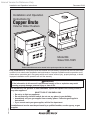
Internet Version for Reference Only
Installation and Operation Instructions
Document 2144
Installation and Operation
Instructions for
Copper Brute
Volume Water Heaters
Model B4
Sizes 500-1825
These instructions are to be stored in the pocket provided on the heater.
FOR YOUR SAFETY: This product must be installed and serviced by a professional service technician,
qualified in hot water heater installation and maintenance. Improper installation and/or operation could
create carbon monoxide gas in flue gases which could cause serious injury, property damage, or death.
Improper installation and/or operation will void the warranty.
WARNING
If the information in this manual is not followed exactly, a fire or explosion may result
causing property damage, personal injury or loss of life.
H2317100-
Do not store or use gasoline or other flammable vapors and liquids in the vicinity of this or
any other appliance.
WHAT TO DO IF YOU SMELL GAS
• Do not try to light any appliance.
• Do not touch any electrical switch; do not use any phone in your building.
• Immediately call your gas supplier from a nearby phone. Follow the gas supplier's
instructions.
• If you cannot reach your gas supplier, call the fire department.
Installation and service must be performed by a qualified installer, service agency, or gas
supplier.
BRADFORD WHITE
C
O
R
P
O
R
A
T
I
O
N
®
Internet Version for Reference Only
BRADFORD WHITE
Page 2
TABLE OF CONTENTS
SECTION 1.
General Information
1.1
1.2
1.3
1.4
Introduction....................................................3
Heater Identification.......................................3
Flow Requirements........................................3
Water Chemistry ............................................4
SECTION 2.
Installation
2.1
2.2
2.2.1
2.2.2
2.3
2.4
2.5
2.6
2.7
2.8
2.9
2.10
2.11
Heater Placement .........................................4
Installation of Indoor Heaters......................... 4
Combustion Air Supply .................................. 4
Venting...........................................................6
Installation of Outdoor Heaters...................... 7
Gas Supply and Piping .................................. 7
Electrical Wiring.............................................8
Water Piping of System ................................. 8
Water Expansion ...........................................9
Pump Performance and Installation .............. 9
Water Pressure............................................10
Tank Installation...........................................10
Two-Temperature System............................ 11
SECTION 3.
Operation
3.1
3.1.1
3.1.2
3.1.3
3.1.4
3.1.5
3.2
3.3
3.3.1
3.3.2
3.4
3.5
Controls - General .......................................14
Electronic Ignition Control............................ 14
Operating Control ........................................14
High Limit Controls ......................................14
Flow Switch .................................................14
Low Water Cut-Off (Optional) ...................... 14
Initial Start-Up..............................................14
To Start Up System......................................15
Start Up Heater............................................15
To Set Temperature and High Limit
Control ....................................................15
To Turn Off Heater .......................................16
To Shut Down System .................................16
SECTION 4.
Maintenance
..................................................................... 16
SECTION 5.
Troubleshooting and Analysis of
Service Problems
..................................................................... 17
Internet Version for Reference Only
B4 Volume Water Heater
SECTION 1.
General Information
Page 3
1.2 Heater Identification
Consult rating plate on the heater. The following
example simplifies the heater identification.
1.1 Introduction
WARNING
All volume water heaters must be installed in
accordance with the procedures outlined in
this manual. The warranty does not apply to
heaters not installed or operated in accordance
with these procedures. Consult local building
and safety codes before proceeding with
work. The installation must conform to the
requirements of the authority having jurisdiction
or, in the absence of such requirements, to
the latest edition of the National Fuel Gas
Code; ANSI Z223.1, National Electrical Code
ANSI/NFPA 70 and/or in Canada CSA B149.1
requirement.
When required by the authority having
jurisdiction, the installation must conform to
the Standard for Controls and Safety Devices
for Automatically Fired Boilers, ANSI/ASME
CSD-1. Any modification to the water heater,
its gas controls, gas orifices, wiring or
draft diverter may void the warranty. If field
conditions require such modifications, consult
factory.
1
2
3
4
5
6
B4
1670
I
N
09
C
1.
2.
3.
4.
5.
Basic heater model.
Input rate X 1000 BTU/hr.
Indoor (I) or Outdoor (E) installation.
Gas type: Natural (N) or Propane (P).
Ignition system: I.I.D. (09) or continuous pilot
(16).
6. Firing rate: On/Off (C), 2-stage (K), 4-stage (L).
Bradford White commercial water heaters are
available in two models: an indoor version and an
outdoor version. Both are available from the factory
(see Figure 1).
1.3 Flow Requirements
For proper operation, all low volume hot water
heaters must have continuous flow through the heat
exchanger when firing. The system pump must be
capable of developing sufficient pressure to overcome
the resistance of the heater plus the entire circulating
system at the designed flow rate.
Pump
295/8
(752)
121⁄4
(311)
C
Gas
Conn.
A
V
Out
58
(1473)
In
Rear
173⁄4
(197)
Front
This manual provides information for the
installation and operation of Bradford White volume
water heaters. It is strongly recommended that all
application and installation procedures be reviewed
completely before proceeding with the installation.
Consult the Bradford White factory, or local factory
representative, with any problems or questions
regarding this equipment. Experience has shown that
most problems are caused by improper installation.
Some accessory items are shipped in separate
packages. Verify receipt of all packages listed on the
package slip. Inspect everything for possible damage
upon delivery, and inform the carrier of any shortages
or impairments. Any such claims should be filed with
the carrier. The carrier, not the shipper, is responsible
for shortages and damage to the shipment whether
visible or concealed.
101⁄4
(260)
Top
29
(737)
281⁄4
(718)
Side
17
(432)
B
Pump
Out
303⁄4
(781)
19
(483) Gas
Inlet
12
(305)
A
Front
Figure 1. Heater Configuration.
In
61
(1549)
14
(356)
73⁄4
(197)
413⁄4
(1060)
Side
4
(102)
Internet Version for Reference Only
BRADFORD WHITE
Page 4
1.4 Water Chemistry
Bradford White equipment is designed for use in
a wide variety of water conditions. The water velocity
maintained in the heat exchanger tubes is kept high
enough to prevent scaling from hard water and low
enough to avoid corrosion from soft water. Ninety-five
percent of the urban areas in the country have water
that is compatible with this equipment, but in some
areas a water supply will contain a large quantity of
scaling chemicals or the water may be extremely soft
and corrosive. In rare situations the water will contain
both scaling chemicals and corrosive chemicals such
as calcium or sodium chloride. These conditions may
be the result of a nearby well or pumping station and
the particular condition may not be characteristic of
the entire city water system.
If an installer observes damage from these
conditions to any water handling equipment in the
area, a factory representative should be contacted
immediately for assistance in minimizing maintenance
costs. If erosion is present, the pump impeller can be
replaced to reduce water velocity. If scaling conditions
are bad, tube cleaning maintenance schedules can be
established to prevent tube burn-out and cracking.
Neglecting the problem could mean serious damage to
the heater and water system.
Scaling can be recognized as a layer deposited
on the inner walls of the tube which reduces the inner
diameter of the tube. Scale can be any color or texture;
smooth or rough, granular or amorphous. Signs of
erosion are generally pitting, cavitation, ridges and
“islands” on the inner walls of the tubes. Since this
condition results from extremely soft water sources,
or as a result of a water softening program, the
internal copper surfaces will be extremely shiny. Other
chemicals, such as chlorine or chlorides in the water,
will cause dark surfaces of erosion.
In areas where the water supply is extremely
corrosive, it is advisable to order the heater with
cupro-nickel tubes in the exchanger.
Damage From Scaling, Corrosion, or Erosion is
Not Covered by the Warranty.
models can be installed on a combustible floor with
a special base assembly which is available from the
factory, or with a base that complies with local code
requirements. See rating plate for part number of the
base assembly.
Do not install a heater on carpeting.
Under the National Fuel Gas Code, ANSI
Z223.1, it is permissible to place the heater on floors
other than non-combustible when the installation
complies with the American Insurance Code.
Figures 2, 3, 4 and 5 show common installation on
combustible flooring.
2.2. Installation of Indoor Heaters
1.
2.
1.
2.
SECTION 2.
Installation
2.1 Heater Placement
The heater must be placed to provide specific
clearances on all sides for maintenance and inspection.
There must also be minimum distances maintained
from combustible surfaces. These clearances also
apply to non-combustible materials because the heater
requires air circulation for proper operation.
Heater should be mounted on a level surface.
An integral combustible flooring base is provided
as standard equipment on outdoor models. Indoor
Locate the water heater to provide adequate
clearance for inspection and service on all sides
(see Table 1). We recommend minimums of 24"
from front (for proper access to and service of
controls) and 18" at water connection end. For
alcove installation (see Figure 6).
Install the heater on a waterproof floor with an
adequate floor drain and a 6" minimum curb on
all four sides to protect the building if heater
repairs are required. The manufacturer will
not be held liable for any water damage in
connection with this heater.
2.2.1 Combustion Air Supply
Copper Brute water heaters must have provisions
for combustion and ventilation air in accordance
with section 5.3, Air for Combustion and
Ventilation, of the National Fuel Gas Code,
ANSI Z223.1, or Sections 7.2, 7.3 or 7.4 of
CSA B149.1, Installation Codes, or applicable
provisions of the local building codes.
A Copper Brute heater may receive combustion
air from the space in which it is installed, or
it can be ducted directly to the unit from the
outside. Ventilation air must be provided in either
case.
In the United States, the most common
requirements specify that the space shall
communicate with the outdoors in accordance
with method 1 or 2, which follow. Where ducts
are used, they shall be of the same cross-sectional
area as the free area of the openings to which
they connect.
Method 1: Two permanent openings, one
commencing within 12 inches (30 cm) of the top
and one commencing within 12 inches (30 cm)
of the bottom, of the enclosure shall be provided.
The openings shall communicate directly, or by
ducts, with the outdoors or spaces that freely
communicate with the outdoors. When directly
communicating with the outdoors, or when
communicating to the outdoors through vertical
Internet Version for Reference Only
B4 Volume Water Heater
Page 5
Clearance
From
Indoor
(inches)
Outdoor
(inches)
Top
Water Conn. Side
Opposite Side
Front
Rear
Vent Pipe*
Hot Water Pipes
30
12
6
Alcove
8
6
Per Code
Unobstructed
24
24
Unobstructed
24
—
Per Code
*1" when using type B Vent (refer to Manufacturer's
Instructions
Table 1. Minimum Heater Clearances
From Combustible Surfaces.
Unit
(Front View)
20 GA
Galvanized
Sheet Metal
Cap
Base
Rail
Base for Combustible Floors
Roofing
Flashing
Roof
4X4 Stringer
Figure 4. Typical Heater Installation with Base for Combustible Floors, Example C.
Base Must Extend Out
Min. 12" On All Sides
Of Heater Frame
Metal Plate 20
Ga. Min.
Under Entire
Heater
Concrete Slab Must Extend Out A
Minimum Of 12" On All Sides
Unit
(End View)
Concrete Blocks Or Tile
Min. 7" High With 3" Min.
Air Openings
Base
Rail
Base For Combustible Floors
Blocks must provide solid base and be
braced so they cannot slip out of place. Air
openings in blocks must be arranged to
provide unobstructed opening through entire
width or length of base.
Concrete Slab - 4" Minimum
Roof - Wood & Steel Construction
Figure 5. Installation on Concrete Blocks or Tile.
Figure 2. Typical Heater Installation with Base for Combustible Floors, Example A.
Water
Heater
Mounting Platform Must Extend Out A
Minimum Of 12" On All Sides
20 GA
Galvanized
Sheet Metal
Cap
Unit
(End View)
Roof
Raised Mounting
Platform (Wood)
ROOM INSTALLATION
(ACCEPTABLE)
A closet is any 4 sided enclosure
which is less than 16* times the total
volume of all the gas fired appliances
within the enclosure.
A room is any enclosure which is at
least 16* times greater than the total
volume of all the gas fired appliances
within the enclosure.
ALCOVE INSTALLATION
(ACCEPTABLE)
Base
Rail
Base For Combustible Floors
CLOSET INSTALLATION
(UNACCEPTABLE)
Flashing
Roof
Figure 3. Typical Heater Installation with Base for Combustible Floors, Example B.
Water
Heater
An alcove suitable for the installation of a water heater is a restricted
section of a room not separated from
the room by a door or partition and
which meets the minimum clearances
for the specific model water heater
listed below.
* When the ceiling height exceeds 8 feet, you are only allowed to consider 8
feet when calculating the total volume of the enclosure.
Figure 6. Alcove Installation.
Internet Version for Reference Only
BRADFORD WHITE
Page 6
ducts, each opening shall have a minimum free
area of 1 square inch per 4000 Btu/hr (5.5 square
cm/kW) of total input rating of all equipment
in the enclosure. When communicating to the
outdoors through horizontal ducts, each opening
shall have a minimum free area of not less than
1 square inch per 2000 Btu/hr (11 square cm/
kW) of total input rating of all equipment in the
enclosure. Table 2 shows data for this sizing
method, for each Copper Brute model.
Method 2: One permanent opening,
commencing within 12 inches (30 cm) of the
top of the enclosure, shall be permitted. The
opening shall directly communicate with the
outdoors or shall communicate through a vertical
or horizontal duct to the outdoors or spaces that
directly communicate with the outdoors and shall
have a minimum free area of 1 square inch per
3000 Btu/hr (7 square cm/kW) of the total input
rating of all equipment located in the enclosure.
This opening must not be less than the sum of the
areas of all vent connectors in the confined space.
Other methods of introducing combustion
and ventilation air are acceptable, providing they
conform to the requirements in the applicable
codes listed above.
In Canada, consult local building and safety
codes or, in absence of such requirements, follow
CSA B149.1.
Heater
Model
Each Opening*
(Square Inches)
500
600
715
850
1010
1200
1430
1670
1825
125
150
179
213
253
300
358
418
457
IMPORTANT: In beauty shops, barber shops,
cleaning establishments and self-service laundries with
dry cleaning equipment, it is important that the water
heater be installed in a location where combustion and
ventilation air is received from a source outside the
building. Please refer to the most recent edition of the
National Fuel Gas Code, ANSI Z223.1, or in Canada,
CSA requirements.
3. (a) In the United States: Exhaust Fans or
Vents: Any equipment which exhausts air from
the heater room can deplete the combustion air
supply or reverse the natural draft action of the
venting system. This could cause flue products
to accumulate in the heater room. Additional air
must be supplied to compensate for such exhaust.
The information in Table 2 is not applicable in
installations where exhaust fans or blowers of
any type are used. Such installations must be
designed by qualified engineers.
(b) In Canada: Follow Canadian standard, CSA
B149.1 or local codes.
4. If a blower or fan is used to supply air to the
heater room, the installer should make sure it
does not create drafts which could cause nuisance
shutdowns of the pilot. If a blower is necessary to
provide adequate combustion air to the heater, a
suitable switch or equivalent must be wired into
the heater control circuit to prevent the heater
from firing unless the blower is operating.
5. The heater must be completely isolated and
protected from any source of corrosive chemical
fumes such as trichlorethylene, perchlorethylene,
chlorine, etc.
1.
*Net Free Area in Square Inches
Area indicated is for one of two openings; one at
floor level and one at the ceiling, so the total net
free area could be double the figures indicated.
For special conditions refer to the latest edition of
ANSI Z223.1. or CSA B149.1
Consult factory if not communicating directly
through the walls with the outdoors.
Note: Check with louver manufacturers for
net free area of louvers. Correct for screen
resistance to the net free area if a screen is
installed. Check all local codes applicable to
combustion air.
Table 2. Minimum Recommended
Air Supply to heater.
2.
2.2.2 Venting
Bradford White heaters have built-in draft
diverters for natural draft operation and must not
be connected to any portion of a mechanical draft
system under positive pressure. The flue outlet
must be connected to a clear, unobstructed vent
of adequate capacity ending above the highest
point of the building with an approved vent cap.
The venting system should be installed according
to the latest edition of ANSI Z223.1 and/or, in
Canada, CSA B149.1 requirement and any local
codes having jurisdiction.
IMPORTANT NOTE: Do not use sheet metal
screws at the snap lock joints of Type B gas
vents.
Do not weld or fasten the vent pipe to the heater
draft hood. The weight of the stack must not rest
on the heater. The draft hood and heater top must
be easily removable for normal heater service
and inspection.
Internet Version for Reference Only
B4 Volume Water Heater
3.
4.
5.
6.
7.
Avoid using long horizontal runs of the vent
pipe, and too many 90° elbows, reductions or
restrictions. Horizontal runs should have at least
a 1/4" rise per foot in the direction of flow. A vent
connector should be supported for the design
and weight of the material used to maintain
clearances and prevent physical damage and
separation of joints.
Avoid ending heater vents near air conditioning
or air supply fans. The fans can pick up exhaust
flue products from the heater and return them
inside the building, creating a possible health
hazard. A minimum of 4 feet horizontal distance
must be maintained from electrical meters, gas
meters, and relief equipment.
Always use double-wall or insulated vent
pipe (Type B or equivalent). In cold weather,
uninsulated outside vents can chill the rising flue
products, blocking the natural draft action of the
venting system. This can create a health hazard
by spilling flue products into the heater room.
Avoid oversize vent piping or extremely long
runs of the pipe which may cause excessive
cooling and condensation. Rule of Thumb: The
total length of the vent, including the connector
and any offset, should not exceed 15 feet for
every inch of vent diameter. Longer total lengths
shown in venting tables are based on maximum
capacity, not condensation factors.
When the installation of a draft fan is necessary
in connecting a venting system to a the heater,
the installation should be engineered by
competent personnel following good engineering
practices. The draft fan supplier should be
consulted for correct size. The installation
should be in accordance with the latest edition
of ANSI Z223.1 and/or, in Canada, CSA
B149.1 requirement and any local codes having
jurisdiction. When a draft fan is installed, a
suitable draft switch must be wired into the
heater control circuit at terminal designated
“Field Interlock” to prevent firing of the heater
unless a positive draft has been established.
Page 7
Window
Or Grill
W
G
N
RO
Indoor
Room
Figure 7. Incorrect Outdoor Installation.
4.
etc. which connect in any way with an inhabited
area of a building. This includes other structures
such as garages or utility rooms (see Figure 7).
Although these models are CSA designed
certified for outdoor installations, such
installations are not recommended in areas
where the danger of freezing exists unless proper
precautions are taken for freeze protection.
2.4 Gas Supply and Piping
Review the following instructions before
proceeding with the installation.
1. Verify that the heater is fitted for the proper type
of gas by checking the rating plate. Bradford
White heaters are normally equipped to operate
below a 2000 foot altitude. Heaters equipped
to operate at higher altitudes have appropriate
stickers or tags attached.
2.3 Installation of Outdoor Heaters
1.
2.
3.
Locate the heater to provide the minimum
clearances as listed in Table 1, “Placement of
Heater”.
Do not place the heater in an enclosure or wall
recess. Avoid locations where wind deflection off
structures might cause down draft. When such
wind conditions are possible, place the heater at
least three (3) feet from the structures.
Never install the heater under any kind of roof
overhang. Do not place the heater below or
adjacent to any doors, windows, louvers, grills,
Note: These figures are for Natural Gas (.65 Sp. Gr.), and are
based on 1/2" water column pressure drop. Check supply pressure with a manometer, and local code requirements for variations. For LPG, reduce pipe diameter one size, but maintain a 1"
minimum diameter. A normal number of Tees and elbows have
been taken into allowance.
Table 3. Gas Piping Sizes.
Internet Version for Reference Only
BRADFORD WHITE
Page 8
8.
Gas Supply
Inlet
To
Equipment
Inlet
Tee
Fitting
Nipple
3" Min.
Cap
Before operating the heater, the complete gas
supply system and all connections must be tested
for leaks using a soap solution. Do not use raw
flame.
Caution
Since some leak test solutions (including soap
and water) may cause corrosion or stress
cracking, the piping must be rinsed with water
after testing, unless it has been determined
that the leak test solution is noncorrosive.
Figure 8. T-Fitting Sediment Trap Installation.
2.
3.
4.
5.
Use the figures in Table 3 to provide adequate
gas piping from the gas meter to the heater.
A trap (drip leg) must be provided ahead of
the gas controls (see Figure 8 ). A manual gas
shutoff valve must also be provided for service
convenience and safety. Check the local codes.
The heater and its individual shutoff valve must
be disconnected from the gas supply piping
system during any pressure testing of that system
at test pressures in excess of 1/2 psig. The heater
must be isolated from the gas supply piping
system by closing its individual manual gas
shutoff valve during any pressure testing of the
gas supply piping system at test pressures equal
to or less than 1/2 psig.
Provide gas supply pressure to the heater as
follows:
Natural Gas
Min. (inches
water column)
Per Rating Plate
Max. (inches
water column)
9
LPG
14
Note: The heater and all other gas appliances
sharing the heater gas supply line must be firing
at maximum capacity to properly measure the
inlet supply pressure. Low gas pressure could be
an indication of an undersized gas meter and/or
obstructed gas supply line.
6. The correct burner manifold gas pressure is
stamped on the rating plate. The regulator is
preset at the factory and normally requires no
further adjustment.
7. The gas manifold and control assembly was
tested and conform to the safe lighting and
other performance criteria specified in the latest
editions of ANSI Z21.13, Low Pressure Boiler
Standard.
2.5 Electrical Wiring
WARNING
The heater must be electrically grounded in
accordance with the most recent edition of
the National Electrical Code, ANSI/NPA 70.
In Canada, all electrical wiring to the heater
should be in accordance with the Canadian
Electrical Code, CSA C22.1 Part 1. Do not rely
on the gas or water piping to ground the metal
parts of the heater. Oftentimes, plastic pipe or
dielectric unions isolate the heater electrically.
Service and maintenance personnel who work
on or around the heater may be standing on
wet floors and could be electrocuted by an
underground heater.
1.
2.
3.
4.
Check heater wiring and pump for correct
voltage, frequency and phase. If the pump circuit
is other than 115V, check to see that the heater is
provided with an appropriate transformer.
Wire the heater and pump exactly as shown in
the wiring diagram supplied with the heater.
The pump and heater must be electrically
interlocked so the heater cannot come on unless
the pump is running.
All field installed electrical safety devices and
all field installed devices (draft switches, relays,
timers, outdoor temperature reset devices, etc.)
can be connected to the heater wiring at points
shown in the wiring diagram designated “Field
Interlock”.
2.6 Water Piping of System
1.
2.
Be sure to provide valves at the inlet and outlet
of the heater so it can be readily isolated for
service. A butterfly or similar type of valve is
recommended.
The pressure relief valve installed in the tapped
opening provided in the outlet header (see
Internet Version for Reference Only
B4 Volume Water Heater
Page 9
Pressure
Relief
Valve
Tempered Water
Hot
Water
24"
Hot
Water
Storage
Tank
Floor
Automatic
Tempering
Valve
Cold
Water
Figure 10. Tempering Valve Installation.
2.7 Water Expansion
Figure 9. Pressure Relief Valve Location.
3.
4.
5.
6.
7.
8.
Figure 9), must be piped, but not fastened, to a
drain or floor sink. The drain pipe must be the
same size as the valve outlet and must pitch
downward from the valve.
Special attention must be given to relief valve
settings in installations where the heater is
located on the ground floor of a tall building. The
static pressure of the system is elevated and could
cause the relief valve to leak. Where no special
setting of the relief valve is ordered, the factory
will furnish a 125 psi setting. Never reduce the
relief valve openings.
Pressure relief valve lever must be tripped at
least once a year to insure that waterways are
clean. When manually operating lever, water will
discharge through drain line. Precautions must be
taken to avoid contact with hot water and water
damage.
The weight of all water and gas piping should be
supported by suitable hangers or floor stands.
Check piping diagrams with local applicable
plumbing, heating and building safety codes.
All two-temperature systems using temperature
valves must have forced recirculation in the low
temperature building loop.
A check valve installed at the hot water inlet to
the tempering valve will prevent cold water from
being drawn in reverse through the tempering
valve into the hot water.
When installing a tempering valve, place at
bottom of antithermosyphon loop at least 24"
high to prevent excessive hot water from entering
mixed water supply. Bring the cold water supply
up from the floor to the valve (see Figure 10).
When cold water is heated the water expands. If
no water is being used during the heat-up period the
expanded water will normally back up into the city
mains.
A water pressure reducing valve installed in the
incoming cold water line may act as a check valve and
prevent the expanded water from moving backward.
This will cause pressure to rise in the heater, which
will be relieved by the pressure relief valve.
If the relief valve pops frequently a mineral
deposit may build up on the valve seat, causing it to
leak.
The following suggestions may solve the
problem:
1. Install a properly sized expansion tank.
2. Replace the installed water pressure reducing valve
with a suitable valve having a back flow port. These
valves have a back flow port which allows water
to flow backwards when the pressure in the system
exceeds the pressure in the mains.
3. Install an auxiliary small relief valve set at 25 psi
less than the main relief valve. The valve must
be piped to a drain and may require occasional
cleaning. It will bleed off the expanded water
and protect the main pressure relief valve from
becoming fouled.
2.8 Pump Performance and Installation
1.
The factory provided pumps on all Copper Brute
heaters are sized to provide proper circulation
through the heater and heater-to-tank circulation
loop (see Figures 11 and 12). If the heater-to-tank
circulating loop does not contain more than 6
elbows or 30 feet of pipe, use pipe fittings in the
loop no smaller than the following:
Model
Pipe Size
500 through 850
1010 through 1825
2"
2-1/2"
Internet Version for Reference Only
BRADFORD WHITE
Page 10
If the heater-to-tank circulating loop contains
more than 6 elbows or 30 feet of pipe, use
pipe or fittings in the loop no smaller than the
following:
Model
Pipe Size
500 through 850
1010 through 1825
2-1/2"
3"
Model
Pump performance requirements are provided in
Table 4 for reference purposes.
2.
To assure free circulation, do not use globe
valves, side outlet tee connections or other
restrictive fittings in heater-to-tank loop.
Copper Brute heaters are not suitable for heating
swimming pools or any other application where
temperature of the water flowing through the
heater remains below the dew point (110°F).
In applications requiring the rapid use of
measured volumes of water, the recovery of the
heater between the time intervals of use must
equal the volume used.
2.9 Water Pressure
It is very important that water pressure in the
system be maintained above 30 psi. If the system
pressure should drop below this, the vapor pressure
of water in the suction side of the pump can cause
hammer and cavitation in the pump and damage the
heater through lack of water circulation.
2.
3.
4.
5.
Be sure the floor is waterproof and structurally
capable of supporting the tank when it is filled
with water.
The tank should be placed so that manholes,
inspection covers, nameplates and drain valves
are accessible.
Be sure the tank is suitable for the water in the
system. Some water is corrosive and requires a
protected tank with a special lining.
If the tank is glass-lined, it should be equipped
with a suitable magnesium anode. It is good
practice to replace the anode when it is
approximately 50% used. The factory warranty
on a glass-lined tank will be void if a satisfactory
anode is not in place at the time of a failure or if
it is consumed by cathodic action.
Make sure the tank connections in the heatertank circulating loop are the proper size as listed
in Section 2.8. If tappings are smaller than the
recommended pipe size, a larger pump may be
required. Consult the factory if in doubt.
Flow
Rate
(GPM)
Head*
Loss
(ft.)
Temp. Rise
Across
Heater, (°F)
500
Soft
Normal
Hard
45
68
90
5.0
9.9
15.7
17
11
8
600
Soft
Normal
Hard
45
68
90
5.1
10.0
15.9
20
14
10
715
Soft
Normal
Hard
45
68
90
5.3
11.0
17.8
24
16
12
850
Soft
Normal
Hard
45
68
90
5.4
11.1
18.1
30
20
15
1010
Soft
Normal
Hard
45
68
90
3.9
7.5
11.7
35
23
18
1200
Soft**
Normal
Hard
68
68
90
7.8
7.8
12.2
27
27
21
1430
Soft**
Normal
Hard
68
68
90
8.1
8.1
12.6
32
32
24
1670
Soft**
Normal
Hard
68
68
90
8.3
8.3
13.0
37
37
28
1825
Soft**
Normal**
Hard
90
90
90
13.5
13.5
13.5
30
30
30
Water Category
Soft
Normal
Hard
2.10 Tank Installation
1.
Water
Category
Grain Hardness per Gal.
1 through 7.5
7.6 through 17
Over 17
* Pressure drop includes loss through 30 feet of pipe and normal fittings when
heater is installed with storage tank. Pipe and fittings are assumed to be 2" on
Models (500-850) and 2 1/2" on Models (1010-1825)
** To prevent erosion, these models must be ordered with cupro-nickel heat
exchanger tubes.
Table 4. Pump Performance Requirements.
6.
7.
8.
Install a pipe in the tank drain fitting that goes to
a floor sink, and install a drain valve. If a floor
sink is not available, install a hose bib.
Hot water tanks in an existing installation are
likely to have a deposit of silt on the bottom.
Therefore, it is important to extend the pump
suction pipe in the tank to a position near the top.
Pipe the return from the heater to the bottom of
the tank.
Incorrect installation can cause rapid failure
of water tanks due to electrolysis. Tanks must
be installed with dielectric connections to
electrically isolate the tank from stray current.
Note that the use of brass or bronze connectors
does not replace the need for dielectric
connections.
Internet Version for Reference Only
B4 Volume Water Heater
2.11 Two-Temperature System
See Figures 13 and 14 for piping schematics.
This system is designed to maintain the tempered
water circulating loop at the desired temperature
during idle periods as well as when there is a
Page 11
demand for hot water. It is recommended for general
purpose water supply including shower and bathing
applications. Water at 180°F is available directly from
the tank.
With
Vertical
Tank
5
1
SU
PP
LY
2
3
4
CW
MU
RE
With
Horizontal
Tank
C.
CWMU
RECIRC.
CIR
3 4
5
Y
PL
P
SU
2
1
Figure 11. Hot Water Supply System
Internet Version for Reference Only
BRADFORD WHITE
Page 12
U
5
3
T
RE
.
RC
CI
M
4 CW
1
N
UR
Y
PL
P
SU
2
2
Figure 12. Hot Water Supply System with Dual Tanks, Building Loop Return and Circulating Pump.
140°F Water
Return From
Bldg.
180°F Water
Return From
Bldg.
H
C
H
C
180°F
Water
To
Bldg.
J
J
Pump
Conventional
Tank
140°F Water
To Bldg.
To
Drain
D
C
Cold
Water
K
To
Drain
Pump
B
Legend
B - Check Valve
To Drain C - Check Valve
D - Tempering Valve
H - Throttling Valves in Building Loop Returns
J - Circulating Pump for Return Loop
K - Service Valves to Isolate Heater and Pump
for Service
Cold Water
Figure 13. Two-Temperature Hot Water Supply System with Vertical Tank.
Internet Version for Reference Only
B4 Volume Water Heater
Page 13
140° Water
Return
From Bldg.
140°
Water
To Bldg.
180°
Water
To Bldg.
H
With
Horizontal
Tank
180° Water
Return
From Bldg.
C
H
J
C
Conventional
Tank
Pump
24" Min.
B
Legend
B - Check Valve in Hot Water Supply
to Tempering Valve
C - Check Valve in Return Line from
Building Loop
D - Tempering Valve
E - Venturi (Suction) Tee
H - Throttling Valves in Building Loop
Returns
I - Circulating Pump for 180° Building
Loop
J - Circulating Pump for 140° Building
Loop
K - Service Valves to Isolate Heater
and Pump for Service
D
To Drain
To
Drain
K
K
Cold
Water
E
180°
Water
To Bldg.
140°Water
Return
From Bldg.
Conventional
Tank
Pump
140°
Water
To Bldg.
With
Vertical
Tank
180°Water
Return
From Bldg.
H
B
D
C
H
C
To
Drain
K
I
E
To Drain
Cold
Water
Figure 14. Two-Temperature Hot Water Supply System.
J
Legend
B - Check Valve in Hot Water Supply
to Tempering Valve
C - Check Valve in Return Line from
Building Loop
D - Tempering Valve
E - Venturi (Suction) Tee
H - Throttling Valves in Building Loop
Returns
I - Circulating Pump for 180° Building
Loop
J - Circulating Pump for 140° Building
Loop
K - Service Valves to Isolate Heater
and Pump for Service
Internet Version for Reference Only
BRADFORD WHITE
Page 14
SECTION 3.
Operation
3.1.3
High Limit Controls:
The manual reset high limit switches are
provided as standard equipment on all heaters.
Automatic reset switches are optionally provided.
The temperature sensing bulb of the switch is
always located in the heater outlet. Burners will
automatically shut down whenever overheating
of water occurs.
3.1.4
Flow Switch:
Standard on all models, the switch is mounted
directly in the header outlet. The flow switch
shuts down all burners in case of low water
condition or pump failure.
3.1.5
Low Water Cut Off: (Optional)
The low water cut off automatically shuts off the
heater whenever the water level drops below the
probe. The probe is located at the heater inlet.
3.1 Controls - General
See Figure 15 for control locations.
3.1.1
Electronic Ignition Controls:
a. Intermittent Ignition:
Pilots are automatically lit when the
operating aquastat calls for heat (System
#9).
The unit performs its own safety check and
opens the main valves only after the pilot is
proven to be lit. Whenever the pilot flame
is interrupted, the main gas valve closes
within 0.8 seconds.
b. Electronically Supervised Standing Pilot
System (System #16):
When pilot flame fails, the ignition control
module responds in less than 0.8 seconds
and provides 100% safety shutdown.
3.1.2
Operating Controls:
Electrically Operating Controls:
Copper Brute units are equipped with operating
temperature. The temperature sensing bulb is
located in the heater inlet.
3.2 Initial Start-Up
Before placing the heater in operation, be certain
that the heater is filled with water and all air is purged
from the system. Once the heater is connected to the
gas supply, the automatic safety shutoff devices must
be checked.
1. Before beginning the tests, make sure the main
manual gas valve, and any other heater firing
valves are in the “OFF” position.
Rating Plate
Flow Switch
Pressure Relief
Valve
Ignition Control
In
Manual
Pilot
Valve
Out
Manual
Main Gas
Valve
Transformer
Safety
Gas
Valve
Operating Control
(Aquastat)
Terminal Strip
Operating
Gas Valve
Figure 15. Control Components.
Hi-Limit
Internet Version for Reference Only
B4 Volume Water Heater
Page 15
2.
Make sure the heater’s power switch is in the
“ON” position. After placing the manual pilot
gas valve in the open position and resetting all
safety devices, (high limit, pressure switch, lowwater cutoff, etc.) pilot(s) can be lit following the
procedure located on the heater rating plate.
3. Once the pilot(s) is lit and has been established
for five minutes, the flame failure response time
should be checked as follows:
System 9 - (Intermittent ignition): With this
system pilots are automatically lit when the operating
controls call for heat. If the pilot flame fails for any
reason, the main valve is shut off within one second
and the pilot spark ignition is initiated until the pilot
flame has been reestablished. On propane systems, unit
locks out for safety. This sequence should be checked
by turning off the manual pilot gas valve, and, at the
same time, monitoring the audible sparking at the pilot
burner and signal interruption to the main valve.
3.3.1 Start Up Heater
Be certain system pump is running, then proceed
as follows:
1. Turn off main electrical switch.
2. Turn off all manual gas valves and wait five
minutes (see Figure 16).
3. Set operating control to lowest setting.
4. Slowly turn manual gas valve to “ON”.
OFF
OFF
3.3 To Start Up System:
ON
ON
ON
System 16 - (Electronically supervised standing
pilot system): Extinguish the pilot flame by placing
the manual pilot valve in the closed position, and at
the same time, begin recording the time it takes for the
output signal from the electronic ignition control to
be interrupted. The signal interruption can be detected
either with a test light or a voltmeter. The response
time should never exceed one second.
4. With the pilots lit, initial activation of the main
burners can be achieved by slowly opening
the main manual valve. The result should be a
smooth lighting of the main burners.
Hi-Limit Checkout:
After running the heater for a long enough
period, bring the water temperature within the range of
the hi-limit and slowly back off the high limit setting
until the heater shuts off. The main burners should
reignite when the hi-limit is reset and turned back up
to its original setting. The heater should now run until
it shuts off automatically on operating aquastat.
Pilot Valve
Main Gas Valve
ON
Pilot Valve
ON
OFF
ON
Caution
Propane gas is heavier than air and sinks to
the ground. Exercise extreme care in lighting
the heater when so equipped.
ON POSITION
OFF POSITION
Main Gas Valve
Figure 16. Gas Manual Valves.
5.
Reset all safety valve switches (manual reset high
limit and low water cut off).
6. Open manual pilot valve. Turn on main electrical
switch.
7. Set temperature controller to desired temperature.
Pilot will light automatically to ignite main
burners whenever the aquastat calls for heat.
For standing pilot system, press on pilot relay
knob, see Figure 17, light pilot and keep relay knob
depressed for one minute then release. Once the pilot
is lit, the power is supplied through the aquastat to the
main gas valve.
3.3.2 To set the temperature and highlimit controls:
When using a tank aquastat:
Set the tank aquastat to the desired tank
temperature. Set the heater temperature control 20°F
higher than tank aquastat. Set the manual reset high
limit 50°F higher than tank aquastat. Example: If
desired temperature is 140°F, set the tank aquastat at
140°F, set the heater temperature control at 160°F, and
set the manual reset high limit at 190°F. If the heater
is equipped with a pump time delay, the three-position
switch on the side of the heater can be put into the
“Auto Pump” position, so that the pump will only run
when the tank aquastat calls for heat. Then, when the
call for heat is satisfied, the heater will turn off, but
the pump will run for the set amount of delay time
(adjustable between 0.1 and 10 minutes).
Internet Version for Reference Only
BRADFORD WHITE
Page 16
Figure 18. Main Burner Flame Pattern.
5.
To shut down heater, turn off all manual gas
valves and electrical disconnect switches. Whenever
danger of freezing exists, shut off water supply and
remove drain plug in the bottom of front header
cover. Drain every part of system subject to freezing
temperature.
Keep heater area clear and free from combustible
material, gasoline and other flammable
vapors and liquids (see Table 1 for minimum
clearances).
Be certain all combustion air and ventilation
openings are unobstructed.
Check for fouling on the external surfaces of
the heat exchanger every six months. (NOTE:
After installation and first start-up, check the heat
exchanger for fouling after the following periods
of operation: 24 hours, 7 days, 30 days, 90 days,
and once every six months thereafter).
Fouling on the external surfaces of the heat
exchanger is caused by incomplete combustion
and is a sign of combustion air and/or venting
problems. As soon as any fouling is observed,
the cause of the fouling should be corrected (see
Section 5, Troubleshooting Guide). The heat
exchanger can be checked by locating a mirror
under the burners with a flashlight. An alternate
method is to remove the venting and top panel as
necessary to inspect from above. Also check the
vent system for defects at this time.
a. If cleaning is required, shut off all electrical
and gas supply to the heater.
b. To expose the heat exchanger:
SECTION 4.
Maintenance
Remove flue pipe, top of unit, rear upper jacket,
flue collector rear panel and heat exchanger
baffles.
Pilot Reset
Switch
Figure 17. Pilot Safety Relay.
When a tank aquastat is not used:
The pump on the heater must run continuously,
so the heater's temperature control will sense the tank's
water temperature. Set the heater temperature control
to the desired tank temperature. Set the manual reset
high limit 50°F higher than the heater temperature
control. Example: If desired temperature is 140°F, set
the heater temperature control at 140°F, and set the
manual reset high limit at 190°F.
3.4 To Turn Off Heater:
1.
2.
Turn off main electric switch.
Close all manual gas valves.
3.5 To Shut Down System:
1.
2.
3.
4.
Lubricate the water circulating pump (see
instructions found on the pump).
If a strainer is employed in a pressure reducing
valve or in piping, clean it every six (6) months.
At start-up and every six (6) months thereafter,
the pilot and main burner flame should be
observed for proper performance (see Figure 18).
See attached lighting and shut-down instructions
for proper pilot flame pattern). If flame has the
appearance of “sooting” tips, check for debris
near orifices. Call serviceman.
Inspect the venting system for obstruction,
leakage and corrosion at least once each year.
6.
7.
Indoor Models:
Outdoor Models:
Remove vent top assembly, rear upper jacket,
flue collector rear panel and heat exchanger
baffles.
c. Remove all burners:
It is usually more convenient to remove
the burner tray assembly. Disconnect
sensor wire, ignition cable (or thermocouple
generator) and pilot gas line. Disconnect
manifold inlet union(s). Remove the four
(4) retaining screws. Grasp burner/pilot
assembly firmly at the front. Push it back,
disengaging it from the gas orifice. Lower
the front of the burner (to avoid damaging
pilot shield) then remove the burner tray.
Internet Version for Reference Only
B4 Volume Water Heater
Caution
Black carbon or green soot on a dirty heat
exchanger can, under certain conditions, be
ignited by a random spark or open flame. To
prevent this unlikely occurrence, dampen the
soot deposits with wet brush or fine water
spray before servicing or cleaning the heat
exchanger.
8.
9.
With a wire brush, remove soot and loose scale
from heat exchanger. Clean fallen debris from
bottom of heater. Make sure burner ports are
clear and pilot assembly is free of debris.
d. Reassemble in reverse order: Be sure the
heat exchanger baffles are replaced.
The gas and electric controls installed on heaters
are engineered for both dependable operation
and long life, but the safety of this equipment
completely depends on their proper functioning.
It is strongly recommended that the basic items
be checked by a competent serviceman every
year and replaced when necessary. The basic
controls are:
a. Water temperature controls.
b. Pilot safety system.
c. Automatic electric gas valve(s).
d. Flow sensing safety device.
Low water cutoffs should be inspected every six
(6) months, including flushing of float types.
Page 17
c.
2.
Tube cleaning kit consisting of reamer,
stainless steel brush, speed handle and
handle extensions.
d. Heater thermometer (with 1/2" NPT well)
100-240°F.
In addition, the heater should be equipped with
a system pressure gauge with proper ranges for
heater operation.
I. HEATER WILL NOT FIRE.
Possible Cause
A. Electric power is off
A. Check to see that main power
switch is “ON.” Use testing
device to trace power to
heater junction box.
B. Operating or safety control
has opened circuit to electric
gas valve.
B. Turn off power. Use continuity
across terminals of each
operating and safety control
switch up to the electric gas
valve. Replace effective
control.
C. Pilot flame is out.
C. Relight pilot per instruction.
D. Manual reset device has
tripped.
D. Follow instructions for startup. Reset Pilot safety and all
manual reset safety switches
and reset manual safety gas
valve.
E. No gas pressure to burners.
E. Trace gas line to service
shutoff cock. If service cock is
open, trace gas line to meter.
If no pressure is present at
meter, call for public utility
service. If gas is present in
heater inlet, check pressures
in following sequence:
(1) downstream from pressure
regulator. (2) downstream
from electric gas valve.
Replace or adjust as
necessary.
F. Electric gas valve operator is
burned out or shortened.
F. Disconnect wiring harness at
gas valve terminals. Check
continuity to actuator coil. If
open circuit or short is
NOTE: Warranty does not cover any damage
caused by lack of required maintenance or improper
operating practices.
10. Both modulating and stage valve are adjusted at
the factory for minimum permissible rates and
should not be readjusted.
SECTION 5.
Troubleshooting and Analysis of
Service Problems
1.
For proper service and problem diagnosis of the
heater and heater system, the following tools are
required:
a. Gas pressure test kit with range from zero
to 14 W.C. Either a slack tub manometer or
an accurate gas pressure gauge is acceptable
with proper adapters which will connect to
the available fittings in the line and on the
gas valve.
b. Multi-meter with the following ranges:
0 to 500 volts A.C.
0 to 1000 ohms continuity.
What To Do
Internet Version for Reference Only
BRADFORD WHITE
Page 18
II. HEATER IS POUNDING, KNOCKING OR EMITTING STEAM FROM RELIEF VALVES.
Possible Cause
A. Low or no water flow.
What To Do
A. This condition is usually
caused by lack of adequate
water flow through heater.
Check the following:
1. Is the heater wired into the
pump circuit so that the heater
cannot fire unless the pump is
running?
2. Check to see that all valves
in system are open to be
sure that water can circulate
through the heater and the
system.
3. If the system has automatic
water valves (2-way or 3-way)
that can cut off the water flow
through the heater check to
see that they are equipped with
end-switches which shut the
heater down when the water
flow through the heater is
reduced by 70% from full flow.
4. Examine pump for clogged
impeller.
B. Low or no system pressure.
B. Clean strainer in pressure
reducing valve. Look for closed
valve water line or a leak in the
system.
C. Clogged “Y” strainer.
C. Remove strainer element and
clean screen.
D. Debris from system piping
is blocking tubes.
D. Remove header covers.
Examine all tubes and
waterways. Use new gaskets
when reassembling. Clean
out tubes.
E. Scale has formed in tubes.
E. This is always caused by the
inflow of raw water into the
system. Clean tubes with tube
cleaning kit. Determine
hardness. Check water flow,
replace pump for modified
flow if necessary.
III. WATER DRIPPING
IN FIREBOX.
Possible Cause
Tube in heat exchanger has
overheated and ruptured.
What To Do
A tube failure is almost always
caused by (a) scale formation
in the tube or (b) inadequate
water flow through the heater.
IV. PRESSURE RELIEF VALVES LEAKING INTERMITTENTLY OR STEADILY.
Possible Cause
What To Do
A.Static pressure in system
A. Calculate height of water in
exceeds setting of relief valve.
system above heater. Install
new valve with psi setting 25%
above required static system
working pressure. Do not
exceed 160 psi.
B. Expansion tank is waterlogged (if installed).
B. Drain expansion tank, then
reopen it to the system. Look
for leaks in expansion tank
or fittings. Calculate required
volume of expansion tank in
relation to system to determine
if tank is adequate.
V. SOOT IN FLUEWAYS OR IN TUBES, OR NOXIOUS FUMES INDICATIVE OF BAD COMBUSTION.
Possible Cause
What To Do
A. Combustion air supply to
heater room is inadequate.
A. Check air supply opening.
Look for debris in screen or
louvre which covers combustion air opening, or for material
blocking the opening.
B. Stack or vent is blocked or
restrictive.
B. Look for blocked stack and
excessive number of elbows in
stack or excessive length of
horizontal runs.
C.Severe down draft is causing
spillage of flue products into
room.
C.Check for (1) proper vent cap
on stack; (2) adequate height
of stack above roof;
(3) equipment exhausting air
from inside of building; and
(4) proper installation of draft
diverter.
D.Gas pressure to burners is
excessive.
D.Check gas pressure with
nanometer, and adjust with
heater firing at full rate.
E. Heater not fitted for the fuel
supplied.
E. See nameplate for correct fuel.
F. Heater installed at high
altitude without proper
derating.
F. Installations at altitudes in
excess of 2000 ft. above sea
level are subject to jurisdiction
of the local inspection
authorities.
Internet Version for Reference Only
B4 Volume Water Heater
This page intentionally left blank.
Page 19
Internet Version for Reference Only
®
BRADFORD WHITE
C
O
R P
O
R A
T
I O
N
®
Ambler, PA 19002
Tech. Service (800) 334-3393
Service Parts (800) 538-2020
Warranty Service (800) 531-2111
H2317100-
BRADFORD WHITE
Page 20
www.Bradford White.com
Litho in U.S.A. © Bradford White 0602 Document 2144