1
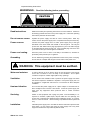
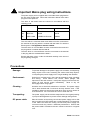
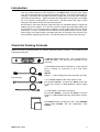
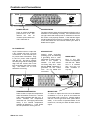
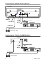
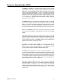
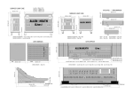
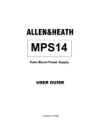
ALLEN&HEATH
ALLEN&HEATH
iPS10
POWER
ON
OFF
DIGITAL SYSTEM BACKUP SUPPLY
POWER ON
ADVANCED POWER SUPPLY TECHNOLOGY
iPS10
Digital Console Backup Power Supply
USER GUIDE
Publication AP6688
Limited Two Year Warranty
This product has been manufactured in the UK by ALLEN & HEATH and
is warranted to be free from defects in materials or workmanship for a
period of two years from the date of purchase by the original owner.
To ensure a high level of performance and reliability for which this
equipment has been designed and manufactured, read this User Guide
before operating.
In the event of a failure, notify and return the defective unit to ALLEN &
HEATH or its authorised agent as soon as possible for repair under
warranty subject to the following conditions:
Conditions Of Warranty
1. The equipment has been installed and operated in accordance with
the instructions in this User Guide
2. The equipment has not been subject to misuse either intended or
accidental, neglect, or alteration other than as described in the User
Guide or Service Manual, or approved by ALLEN & HEATH.
3. Any necessary adjustment, alteration or repair has been carried out
by ALLEN & HEATH or its authorised agent.
4. The defective unit is to be returned carriage prepaid to ALLEN &
HEATH or its authorised agent with proof of purchase.
5. Units returned should be packed to avoid transit damage.
In certain territories the terms may vary. Check with your ALLEN &
HEATH agent for any additional warranty, which may apply.
This product complies with the European Electromagnetic
Compatibility directives 89/336/EEC & 92/31/EEC and the
European Low Voltage Directives 73/23/EEC & 93/68/EEC.
Any changes or modifications to the power supply unit not approved
by Allen & Heath could void the compliance of the product and
therefore the users authority to operate it.
iPS10 User Guide AP6688 Issue 1.
Copyright © 2007 Allen & Heath. All rights reserved
Manufactured in the United Kingdom by Allen & Heath Limited
Kernick Industrial Estate, Penryn, Cornwall, TR10 9LU, UK
http://www.allen-heath.com
2
iPS10 User Guide
Important Safety Instructions
WARNINGS
- Read the following before proceeding :
CAUTION
ATTENTION: RISQUE DE CHOC ELECTRIQUE – NE PAS OUVRIR
Read instructions:
Retain these safety and operating instructions for future reference. Adhere to
all warnings printed here and on the power supply unit. Follow the operating
instructions printed in this User Guide.
Do not remove covers:
Operate the power supply unit with its covers correctly fitted. Refer any
service work on the power supply unit to competent technical personnel only.
Power sources:
Connect the power supply unit to a mains power supply only of the type
described in this User Guide and marked on the rear panel. Use only the
power cord with sealed mains plug appropriate for your local mains supply
as provided with the power supply unit. If the provided plug does not fit into
your outlet consult your service agent for assistance.
Power cord routing:
Route the power cord so that it is not likely to be walked on, stretched or
pinched by items placed upon or against it.
Grounding:
Do not defeat the grounding and polarisation means of the power cord plug.
Do not remove or tamper with the ground connection in the power cord.
WARNING: This equipment must be earthed.
Water and moisture:
To reduce the risk of fire or electric shock do not expose the power supply
unit to rain or moisture or use it in damp or wet conditions. Do not place
containers of liquid on it which might spill into any openings.
Ventilation:
Do not obstruct the ventilation slots or position the power supply unit where
the air flow required for ventilation is impeded. If the power supply unit is to
be operated in a flightcase ensure that it is constructed to allow adequate
ventilation.
Heat and vibration:
Do not locate the power supply unit in a place subject to excessive heat or
direct sunlight as this could be a fire hazard. Locate the power supply unit
away from any equipment which produces heat or causes excessive
vibration.
Servicing:
Switch off the equipment and unplug the power cord immediately if it is
exposed to moisture, spilled liquid, objects fallen into the openings, the
power cord or plug become damaged, during lightening storms, or if smoke,
odour or noise is noticed. Refer servicing to qualified technical personnel
only.
Installation:
Install the power supply unit in accordance with the instructions printed in this
User Guide. Do not connect the output of power supply unit to any other
equipment other than that specified by Allen & Heath.
iPS10 User Guide
3
Important Mains plug wiring instructions.
The power supply unit is supplied with a moulded mains plug fitted to
the AC mains power lead. Follow the instructions below if the mains
plug has to be replaced.
The wires in the mains lead are coloured in accordance with the
following code:
WIRE COLOUR
TERMINAL
European
USA/Canada
L
LIVE
BROWN
BLACK
N
NEUTRAL
BLUE
WHITE
E
EARTH GND
GREEN & YELLOW
GREEN
The wire which is coloured Green and Yellow must be connected to
the terminal in the plug which is marked with the letter E or with the
Earth symbol. This appliance must be earthed.
The wire which is coloured Blue must be connected to the terminal in
the plug which is marked with the letter N.
The wire which is coloured Brown must be connected to the terminal
in the plug which is marked with the letter L.
Ensure that these colour codes are followed carefully in the event of
the plug being changed.
Precautions
4
Damage :
To prevent damage to the power supply unit cosmetics, avoid placing
heavy objects on the unit, scratching the surface with sharp objects,
or subjecting the power supply unit to rough handling and vibration.
Environment :
Protect from excessive dirt, dust, heat and vibration when operating
and storing. Avoid tobacco ash, smoke, drinks spillage, and
exposure to rain and moisture. If the power supply unit becomes wet,
switch off and remove power immediately.
Allow to dry out
thoroughly before using again.
Cleaning :
Avoid the use of chemicals, abrasives or solvents. The power supply
unit is best cleaned with a soft brush and dry lint-free cloth. If the
ventilation grilles become blocked with dust use a vacuum cleaner to
suck the dirt out. Do not remove the cover to clean the unit.
Transporting :
The power supply unit should be transported in the original packing
or purpose built flightcase to protect it from damage during transit.
DC power cable:
Plan the location of the mixing console and power supply unit so that
the DC power and CAT5 cables are not fully extended. Full extension
of the cable can stress the mixing console and power supply unit
connectors and may result in undesired performance. Ensure that
the power cable is located such that it cannot be stood on or tripped
over.
iPS10 User Guide
Introduction
This user guide presents a quick reference to the iPS10 digital console power supply
unit. We recommend that you read this fully before starting. Included is information on
installing, connecting and operating the power supply unit along with panel drawings
and technical specification. Whilst we believe the information in this guide to be reliable
we do not assume responsibility for inaccuracies. We also reserve the right to make
changes in the interest of further product development.
We are able to offer further product support through our worldwide network of approved
dealers and service agents. You can also access our Web site (www.allen-heath.com)
for information on our company and its pedigree, our full product range and our design
philosophy. To help us provide the most efficient service please keep a record of your
power supply unit serial number, and date and place of purchase to be quoted in any
communication regarding this product. The serial number is located on the rear panel.
Check the Packing Contents
Retain the product packing should you need to ship the product in future. You should find the
following components:
iPS10
ALLEN&HEATH
POWER
ON
OFF
DIGITAL SYSTEM BACKUP SUPPLY
POWER ON
ADVANCED POWER SUPPLY TECHNOLOGY
1x iPS10 POWER SUPPLY UNIT. This is packed with its
rubber feet fitted. The feet can be removed for rack
mounting.
1x IEC MAINS LEAD with moulded plug. Check that the
plug is suitable for connection to your local mains
supply.
iPS10/n
Where n = mains voltage 120 (USA), 220 (EU), 240 (UK)
120 USA, 220
1x DC POWER CABLE 2.8m male>female 10-pin.
Part number 003-576. Connects the iPS10 power rails
to the iLive Surface or iDR0 MiniRack backup supply
input.
1x CAT5 CABLE 2.8m RJ45 connections.
Part number AH6831. Connects the iPS10 to the iLive
Surface or iDR0 MiniRack backup temperature monitor
input.
DOCUMENTATION including the User Guide AP6688,
Safety Sheet AP3345, and the Registration Card
AP3594.
iPS10 User Guide
5
The iPS10 Power Supply
The slimline, 2U rack mountable iPS10 power supply unit is a high performance, low noise, universal
mains voltage, switched mode power supply producing the DC voltages required to run the iLive
Surface or IDR0 MiniRack. It is available as an option to provide redundant backup of the internal
mains power supplies fitted in these iLive components. The iLive will operate with either or both
supplies switched on.
Two connecting cables are required between the iPS10 and iLive. The power unit produces 5
different DC voltages and has three independent ground connections. These connect to the iLive via
a 2.8 meter long multicore DC cable fitted with 10-pin circular locking connectors. Voltage rail
protection, thermal sensing and fan cooling ensure the power supply unit will operate consistently.
The power unit temperature information connects to the iLive via a 2.8 meter long CAT5 cable.
Current status may be viewed by the operator on the iLive Surface TouchScreen.
Installation
Free standing
The iPS10 can be operated as a freestanding unit for shelf or floor operation. Check that its plastic
feet are fitted. Ensure adequate air flow around the unit. It must not be covered in any way. Always
stand the unit on a firm flat surface away from any soft furnishings or carpet.
Rack mounting
The iPS10 is designed as a 19 inch rack mount unit and will occupy 2U (3.5 inches) of rack space.
The plastic feet may need to be removed before rack mounting. Retain the feet for future use.
Ensure natural convection of airflow around the unit by allowing good ventilation below, in front of
and behind the unit. Rack equipment known to produce a significant amount of heat should not be
mounted directly below the power supply unit. Forced convection by means of a rack mounted fantray may be desirable in situations where space is restricted and the ambient air temperature is high.
Cables
The DC power and temperature monitor cables are 2.8 meters long to allow the unit to be positioned
away from the console. Make sure the cables are not stretched in any way and are routed to avoid
becoming kinked or damaged. Allow enough service loop for access and removal of the unit.
Ensure all connectors are fully plugged in and locked.
Consideration should be given to the earthing (grounding) arrangement of the system. The iLive
chassis is connected to the mains earth via the power supply unit. Do not remove the IEC power
cord earth connection. A screw terminal chassis grounding post is provided on the rear of the iPS10
for situations where additional earth bonding is required.
88 mm / 3.46"
Dimensions
482 mm / 19"
Do not obstruct the ventilation
slots. Ensure adequate air flow around
the iPS10.
443 mm / 17.4"
Ensure proper grounding. Do not
remove the IEC mains cord earth
(ground) connection.
2U
374 mm / 14.7"
310 mm / 12.2"
6
Do not remove the cover of the
iPS10. There are no user serviceable
parts inside.
iPS10 User Guide
Controls and Connections
ALLEN&HEATH
iPS10
POWER
ON
OFF
POWER ON
DIGITAL SYSTEM BACKUP SUPPLY
ADVANCED POWER SUPPLY TECHNOLOGY
POWER ON/OFF
POWER STATUS
Press to switch the iPS10
power unit on or off. The
internal fan runs at
constant speed while the
unit is switched on.
The blue indicator lights at full brightness while the unit is
switched on and working correctly. If the indicator does
not light check that mains power is switched on and the
IEC mains cord properly inserted. If the indicator lights
at half brightness there may be a voltage rail fault. If this
is the case switch the unit off and contact your Allen &
Heath service agent.
DC POWER OUT
10-pin female socket to output the
5 DC voltage rails and 3 ground
connections. It also has two pins
for power status information. Plug
in the DC power cable supplied
with the unit. Do this by rotating
the male plug until the mating tabs
align with the socket, then insert
fully and tighten the locking screw
ring.
Be careful not to cross
thread the screw ring.
ALLEN&HEATH iPS10
GROUND POST
Chassis metal grounding
(earthing) post for attaching
a grounding wire to other
equipment or metal cases or
racks in the system if
needed. For best results
use heavy duty wire. Note
that the iPS10 metalwork is
grounded via the mains
cord. Do not defeat this
connection.
MAINS INPUT
Plug in the IEC
mains cord supplied
with the unit. Make
sure it is inserted
fully and has not
been modified in
any way.
DO NOT OBSTRUCT VENTILATION OPENINGS.
DO NOT OPEN. NO USER SERVICEABLE PARTS INSIDE.
THIS APPARATUS MUST BE EARTHED BY THE POWER CORD.
BACKUP PSU
AVIS: RISQUE DE CHOC ELECTRIQUE - NE PAS OUVRIR.
WARNING: TO REDUCE THE RISK OF ELECTRIC SHOCK
DO NOT EXPOSE THIS APPARATUS TO RAIN OR MOISTURE.
This device complies with Part 15 of the FCC Rules. Operation is subject to the following two conditions:
(1) this device may not cause harmful interference, and
(2) this device must accept any interference received, including interference that may cause undesired operation.
CONNECT ONLY TO
SPECIFIED A&H
DIGITAL EQUIPMENT
CHASSIS
GROUND
CAUTION: FOR CONTINUED PROTECTION AGAINST RISK OF FIRE REPLACE FUSE
WITH SAME TYPE AND RATING. DISCONNECT SUPPLY BEFORE CHANGING FUSE.
ATTENTION: REMPLACER PAR UN FUSIBLE STRICTEMENT IDENTIQUE EN VALEURS.
COUPER L'ALIMENTATION AVANT DE CHANGER LE FUSIBLE.
MAINS INPUT
FUSE
T5AL 250V
20MM
SERIAL NUMBER
Made in the UK by ALLEN&HEATH LIMITED
100 - 240V~
47-63Hz ~ 320W MAX
TEMPERATURE MONITOR
MAINS FUSE
RJ45 socket to output the temperature
status information to the iLive. Use the
CAT5 cable supplied with the unit. A
sensor monitors the temperature
inside the unit. The supply shuts down
safely if the internal temperature
reaches 85 degrees C. A fan inside
the unit prevents it running too hot.
To check or replace the fuse use a flat bladed
screwdriver or coin to push in and rotate the
fuse holder until it pops out. Always replace
with the correct type and value (T5AL 20mm
250V). In the event of repeated failure of the
mains fuse, consult your Allen & Heath service
agent.
iPS10 User Guide
7
Connecting the iPS10 to the iLive Surface
iLIVE SURFACE
Surface CPU power on
Internal PSU on
Backup PSU on
Female plug
INTERNAL PSU
Cable retention clip
DC CABLE
10way
Male plug
TEMPERATURE MONITOR CABLE
CAT5
iPS10 BACKUP PSU
MAINS
IEC MAINS CABLES
Mains power 100 - 240V AC
Connecting the iPS10 to the iDR0 MiniRack
iDR0 MINIRACK
MAINS
INTERNAL PSU
Female plug
DC CABLE
10way
Male plug
TEMPERATURE MONITOR CABLE
CAT5
iPS10 BACKUP PSU
MAINS
IEC MAINS CABLES
Mains power 100 - 240V AC
8
iPS10 User Guide
Notes on Operating the iPS10
The iPS10 is intended as a backup power supply for iLive system
components. At the time of release of this user guide it can be used
with any of the 4 surfaces (iLive-80, iLive-112, iLive-144 and iLive176) and the iDR0 DSP MiniRack. These components can operate
using their internal mains power units only. Connecting the iPS10 in
addition to the internal supply provides dual supply redundancy. The
component can be operated with either or both supplies switched
on. It continues to operate without interruption if either supply is
switched off or loses power.
The iPS10 features a universal mains voltage input that can accept
any AC mains voltage between 100 and 240V AC. We recommend
that it is run on the same power distribution that feeds the iLive unit
being connected to. For protection against temporary loss of mains
power an external UPS (uninterruptible power supply) could be used.
Make sure the iPS10 and the iLive unit being connected to are both
turned off before plugging or unplugging the mains and DC POWER
cables.
Blue LED indicators on the CPU module at the rear of the iLive
surface light to indicate that the power supplies are switched on and
working correctly. There is one for the internal surface supply and
one for the backup supply. The iPS10 sends power good/fail status
signals to the iLive via its 10way DC cable.
The iPS10 front panel blue POWER ON indicator lights at full
brightness to indicate normal operation. If a voltage rail fault is
detected then it reduces to half brightness. If this happens, switch
the unit off and contact your Allen & Heath service agent.
The iPS10 has an internal fan to assist cooling and ventilation. The
fan runs at constant speed. Thermal protection is provided to safely
shut down the power rails if the unit reaches 85 degrees C internally.
If this happens check that the fan is running, the ventilation slots are
not blocked and there is adequate airflow around the unit. Switch the
unit off and allow it to cool. When it has cooled sufficiently it
automatically resets and resumes operation.
The CAT5 cable provided with the unit is used to send the
temperature status to the iLive. The current temperature measured
within the iPS10 is displayed on the iLive Surface TouchScreen
Utility/Diagnostics/Temperature Display page. The minimum and
maximum temperatures reached are also displayed. These values
can be reset.
iPS10 User Guide
9
Technical specification
Technology
Switched mode with power factor correction
Mains input
IEC connector
Mains voltage
85 to 250V AC, 47 to 63 Hz ~
Power consumption
320W max
Mains fuse
T5AL 250V 20mm.
DC voltage rails
+8, +18, -18, +24, +57 V DC
DC output
10-pin female circular chassis mounted socket
Temperature sense
RJ45 connector
DC cable
2.8m multicore male to female. A&H part number 003-576
Temperature cable
2.8m CAT5 RJ45. A&H part number AH6831
Protection
Under voltage detection and thermal sensing
Cooling
Fan assisted. Thermal shutdown at 85 degrees C
Installation
2U rack mount (integral ears) or free standing (plastic feet fitted)
Dimensions
Rack mounted 482 x 310 x 88mm (2U) 19” x 12.2” x 3.46”
Free standing 482 x 310 x 92mm (including feet) 19” x12.2” x 3.6”
Minimum clearance at rear for connectors 64mm (2.5”) min
Packed 580 x 510 x 210mm 22.9” x 20” x 8.3”
Weight
Unpacked 7 kg (15.4 lbs)
88 mm / 3.46"
Packed 8.5 kg (18.7 lbs)
482 mm / 19"
443 mm / 17.4"
2U
374 mm / 14.7"
310 mm / 12.2"
10
iPS10 User Guide