1
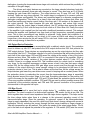
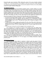
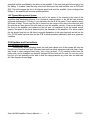
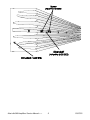
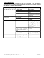
ALESIS
MATICA 500/900
(A4/A8)
Service Manual
P/N: 8-31-0030-A
The information in this document contains privileged and confidential information.
It is intended only for the use of those authorized by Alesis. If you are not the
authorized, intended recipient, you are hereby notified that any review,
dissemination, distribution or duplication of this document is strictly prohibited. If
you are not authorized, please contact Alesis and destroy all copies of this
document. You may contact Alesis at [email protected] or at
[email protected].
Copyright Alesis, LLC
Confidential
Alesis Service Manual
8-31-0030-A
Preface
This document is intended to assist the service technician in the operation,
maintenance and repair of the Alesis device. Together with the User Reference
Manual, this document provides a complete description of the functionality and
serviceability of the Device. Any comments or suggestions you may have
pertaining to the document are welcome and encouraged.
READ THIS!
In addition to any purchase price that Alesis may charge as consideration for Alesis selling or
otherwise transferring this service manual (“Manual”) to you, if you are not a service and repair
facility (“Service Center”) authorized by Alesis in writing to be an authorized Service Center,
Alesis sells or transfers the Manual to you on the following terms and conditions:
Only Service Centers authorized by Alesis in writing are authorized to perform service and repairs
covered by an Alesis warranty (if any), and transfer of the Manual to you does not authorize you
to be an authorized Service Center. Therefore, if you perform, or if the Manual is used to
perform, any service or repairs on any Alesis product or part thereof, any and all
warranties of Alesis as to that product and any service contract with Alesis for that
product shall be voided and shall no longer apply for such product, even if your services
or repairs were done in accordance with the Manual.
All service or repairs done by you or with reference to the Manual shall be solely your
responsibility, and Alesis shall have no liability for any such repairs or service work. All such
service or repairs are performed at the sole risk of the person performing the service or
repairs. You agree that all such work will be performed in a competent, professional and safe
manner at all times and to indemnify and fully hold Alesis and its successors and assigns
harmless in the event of any failure to so perform.
Your purchase of the Manual shall be for your own ultimate use and shall not be for purposes of
resale or other transfer.
As the owner of the copyright to the Manual, Alesis does not give you the right to copy the
Manual, and you agree not to copy the Manual without the written authorization of Alesis. Alesis
has no obligation to provide to you any correction of, or supplement to, the Manual, or any new or
superseding version thereof.
Alesis shall have the right to refuse to sell or otherwise transfer repair parts or materials to you in
its sole discretion. You shall not use, sell or otherwise transfer spare or replacement parts
supplied by Alesis to you (i) to repair or be used in products manufactured for or by third parties
or (ii) to any third parties for any purpose.
You shall not make any warranties or guarantees with respect to the products of Alesis or the use
thereof on behalf of Alesis or in your own name.
The foregoing describes the entire understanding related to sale or transfer of the Manual to you,
and no other terms shall apply unless in a writing signed by an authorized representative of
Alesis.
All Trademarks are property of their respective companies.
Confidential
Alesis Service Manual
8-31-0030-A
Warnings
TO REDUCE THE RISK OF ELECTRIC SHOCK OR FIRE, DO NOT EXPOSE
THIS PRODUCT TO WATER OR MOISTURE.
The arrowhead symbol on a lightning flash inside a triangle is
intended to alert the user to the presence of un-insulated
"dangerous voltage" within the enclosed product which may be of
sufficient magnitude to constitute a risk of electric shock to persons.
The exclamation point inside a triangle is intended to alert the user
to the presence of important operating, maintenance and servicing
instructions in the literature which accompanies the product.
REPAIR BY ANY PERSON OR ENTITY OTHER THAN AN AUTHORIZED
ALESIS SERVICE CENTER WILL VOID THE ALESIS WARRANTY.
PROVISION OF THIS MANUAL DOES NOT AUTHORIZE THE RECIPIENT TO
COMPETE WITH ANY ALESIS DISTRIBUTOR OR AUTHORIZED REPAIR
SERVICE CENTER IN THE PROVISION OF REPAIR SERVICES OR TO BE
OR MAKE REPAIRS AS AN AUTHORIZED SERVICE CENTER.
ALL REPAIRS DONE BY ANY ENTITY OTHER THAN AN AUTHORIZED
ALESIS SERVICE CENTER SHALL BE SOLELY THE RESPONSIBILITY OF
THAT ENTITY, AND ALESIS SHALL HAVE NO LIABILITY TO THAT ENTITY
OR TO ANY OTHER PARTY FOR ANY REPAIRS BY THAT ENTITY.
Regarding the Power Supply Fuse
CAUTION: The product under service may employ the use of a
replaceable fuse. Danger of fire or electrocution if fuse is
incorrectly replaced. Replace with only the same type or
equivalent type recommended by the equipment manufacturer.
Regarding the Internal Battery
CAUTION: The product under service may employ the use of a
internal battery. Danger of explosion if battery is incorrectly
replaced. Replace only with the same or equivalent type
recommended by the manufacturer. Dispose of used batteries
according to the manufacturer's instruction.
Confidential
Alesis Service Manual
8-31-0030-A
Safety Instructions
Carefully read the applicable items of the operating instructions and these safety
suggestions before using this product. Use extra care to follow the warnings
written on the product itself and in the operating instructions. Keep the operating
instructions and safety suggestions for reference in the future.
1. Power Source. The product should only be connected to a power supply which is described
either in the operating instructions or in markings on the product.
2. Power Cord Protection. AC power supply cords should be placed such that no one is likely to
step on the cords and such that nothing will be placed on or against them.
3. Periods of Non-use. If the product is not used for any significant period of time, the product's
AC power supply cord should be unplugged from the AC outlet.
4. Foreign Objects and Liquids. Take care not to allow liquids to spill or objects to fall into any
openings of the product.
5. Water or Moisture. The product should not be used near any water or in moisture.
6. Heat. Do not place the product near heat sources such as stoves, heat registers, radiators or
other heat producing equipment.
7. Ventilation. When installing the product, make sure that the product has adequate
ventilation. Improperly ventilating the product may cause overheating, which may damage the
product.
8. Mounting. The product should only be used with a rack which the manufacturer
recommends. The combination of the product and rack should be moved carefully. Quick
movements, excessive force or uneven surfaces may overturn the combination which may
damage the product and rack combination.
9. Cleaning. The product should only be cleaned as the manufacturer recommends.
10. Service. The user should only attempt the limited service or upkeep specifically described in
the operating instructions for the user. For any other service required, the product should be
taken to an authorized service center as described in the operating instructions.
11. Damage to the Product. Qualified service personnel should service the unit in certain
situations including without limitation when:
a. Liquid has spilled or objects have fallen into the product,
b. The product is exposed to water or excessive moisture,
c. The AC power supply plug or cord is damaged,
d. The product shows an inappropriate change in performance or does not operate
normally, or
e. The enclosure of the product has been damaged.
Confidential
Alesis Service Manual
8-31-0030-A
General Troubleshooting
While this manual assumes that the reader has a fundamental understanding of electronics and
basic troubleshooting techniques, a review of some of the techniques used by our staff may help.
1. Visual Inspection - A short visual inspection of the unit under test will often yield results without the
need of complex signal analysis (burnt, or loose components are a dead giveaway).
2. Self Test - Alesis products that utilize microprocessor control contain built in test software which
exercises many of the units' primary circuit functions. Self test should always be done following any
repair to ensure basic functionality.
3. Environmental Testing - Applying heat and cold (heat gun/freeze spray) will often reveal thermally
intermittent components (Clock crystals, I.C.s, and capacitors are particularly prone to this type of
failure).
4. Burn in Testing - Leaving a unit running overnight often reveals intermittent failures such as
capacitors that begin to leak excess current after a significant amount of time.
5. Cable Checks - Wiggling cables can reveal intermittent failures such as loose cables or poorly
soldered headers. Remember to check power supply cables as well.
6. Flexing the PC Board - Poor solder joints and broken traces can often be found by pressing the PC
Board in various places.
7. Tapping Components - Sometimes tapping on a component (particularly crystals) will cause it to fail.
8. Power Down/up - Turning the unit off and back on rapidly several times may reveal odd reset and/or
power supply failures.
9. Reset Threshold - A Variac (variable transformer) can be used to check reset threshold levels. This
can be particularly useful in helping customers with low line problems.
10. Compressors - Using a compressor/limiter is often helpful when attempting to solve low level noise
problems, as well as assisting with DAC adjustments.
11. Sweep Tests - Sweep generators are very useful in checking the frequency response envelopes of antialiasing filters.
12. Piggybacking - Piggybacking I.C.s is particularly useful when troubleshooting large sections of logic.
This is especially true when working with older units.
Alesis A4/A8 Service Manual------
iv
03/07/03
Table of Contents
PREFACE ......................................................................................................... ii
WARNINGS ...................................................................................................... ii
SAFETY SUGGESTIONS ................................................................................. iii
General Troubleshooting ...................................................................................iv
1.00 Theory of Operation .................................................................................. 1
1.10 Input Section................................................................................... 1
1.20 Pre-Amp Section ............................................................................ 2
1.30 Main Amplifier Section .................................................................... 2
1.40 Output Device Protection................................................................ 3
1.50 Bias Circuit ..................................................................................... 3
1.60 Speaker Protection ......................................................................... 4
1.70 Fan Speed Control.......................................................................... 4
1.80 Thermal Management System........................................................ 5
2.00 Updates and Corrections........................................................................... 5
2.10 Stripped Heat Sinks ........................................................................ 5
2.20 New Case Bracket Insulator(s) ....................................................... 7
2.30 Transformer Insulators.................................................................... 8
3.00 Troubleshooting......................................................................................... 9
4.00 A4 Service Parts List ................................................................................. 10
4.10 A8 Service Parts List ...................................................................... 13
5.00 Service Manual History ............................................................................. 16
INDEX ............................................................................................................... 17
Alesis A4/A8 Service Manual------
v
03/07/03
1.00 Theory of Operation
The A4/A8 amplifiers are basic stereo amplifiers. They have 0dBm input sensitivities for
rated output at 4:, with the ability to drive any load impedance from 2: to an open circuit. They
have balanced inputs via Neutrik combination connectors providing XLR and 1/4" TRS
connections and also a barrier strip. The output of the amplifier is obtained by way of four five
way binding posts. Reference designations in the text refer specifically to the A4 amplifier except
where otherwise noted. Though reference designations between the two units are different, the
designs are virtually identical. The only significant differences occur in the output section (since
the A8 is required to handle much more power than the A4).
Here are some of the major features and building blocks of the Matica:
à An input balanced to unbalanced converter.
à A second stage pre-amp and an amplifier gain stage utilizing a monolithic front end with
discrete complimentary transconductance stage and a complimentary output stage in a
common collector configuration.
à Output device protection is accomplished with a conventional volt-amp current limiter circuit.
The output devices use a new perforated emitter technology unique to MOTOROLA. The
output devices are driven by similar technology devices, but they have been optimized for
extremely linear current gain with a unity gain bandwidth (Ft) of 50 MHz.
à The speakers are protected by output relays. They are activated during the first 3 to 5
seconds the amplifier is turned on. Also, if a DC condition exists at the output of the amplifier
or the amplifier is driven to full output below 5Hz the relays will be activated.
à Thermal management and protection are accomplished with a large heavy aluminum
extruded heat sink the is fan cooled. If the sink gets warmer than 55 deg. C, the fan is
automatically stepped up in speed and if the heat sink gets warmer than 80 deg. C the fan is
run at high speed and the output relays are activated to disconnect the load until the unit has
cooled to 65 deg. C. There is also a unique feature of the amplifier fan circuit in that when the
amplifier is providing an output signal of a little more that a watt the fan speed is modulated
or increased by the signal. This will help get longer run times with the amplifier under
extreme load conditions.
1.10 Input Section
The input stage is made up of a dual Signetics 5532A op amp. This is a low noise
selected version of the 5532. One half of the dual is used for each channel. The circuit is a basic
balanced to unbalanced converter. It can be driven unbalanced but 6dB differences in gain may
result for various hookups. If the (+) input is driven with the (-) input grounded the gain will be
unity. If the (+) input is driven with the (-) input left open there will be a gain reduction of 6dB.
This is not recommended as a noisier condition may result. If the (-) input is driven, gain will be
unity and will not change with the grounding or ungrounding the (+) input The maximum input
level before clipping in about +21dBm. Since there is no level control in front of the converter this
is the maximum input level for the amplifier. Connections to the Alink connector are between R1,
R2 and R3, R4. These are provided so an outboard impedance may be connected to modify the
gain and overload characteristics as well as its frequency response. Following the amplifier is a
passive low pass (R7, C1) filter that begins to limit the high frequency gain of the amplifier.
Alesis A4/A8 Amplifiers Service Manual------
1
03/07/03
1.20 Pre-Amp Section
The pre-amp section also uses the Signetics 5532A op amp. The circuits of the pre-amp
are of opposing signal polarity to provide push pull characteristics and are connected via the
stereo/bridge switch. Each of the two pre-amp channels has 15.7 dB of gain but channel A is
inverting and channel B is not.
Since the main amplifier is inverting, channel A will not invert the signal and channel B
will. Doing this facilitates two things. When the stereo/bridge switch is in the bridge mode
channel B will already be out of phase with A so no signal inversion will have to be done to
achieve bridge operation. Also by operating B out of phase all the time, (even in stereo
operation) getting the phase of the signal flipped back at the speaker terminals, the amplifiers
low frequency power bandwidth will be increased. This allows the power supply to be utilized
more efficiently.
This section also shapes the bandwidth of the amplifier further via another low pass pole
being added to each stage. First and second stage high pass filtering occurs via the 100uf
coupling capacitors preceding the volume pots and after the pre-amp stages. The pre-amp
stages drive the main amplifier directly.
ALINK connections at the junction between R8, C2 and R13, C5 are for sending the
output signal of the input stage at a low impedance for use with auxiliary equipment. The
connection between R9, R10 and R14, R17 are to be used to for defeating the level controls by
supplying an input signal from a very low source impedance to swamp out the signal from the
pots.
1.30 Main Amplifier Section
The main amplifier is composed of four sections:
à
The monolithic front end.
à
A complimentary voltage gain stage or transconductance stage
à
The output driver
à
The output stage
The amplifier is configured in the inverting mode. This allows for the inputs of the op amp
to remain at a 0 voltage potential and ease operation on a +/- 15 volt supply. The large voltage
swing is accomplished with a discrete, complimentary darlington connected transconductance
stage Q1, Q2, Q3, and Q4. The current in the transconductance stage is set by the voltage
divider network made up of R19, R20, R21, and R22. The first transistor in the darlington is a
TO-92 packaged device with the current set by R27, and R28. The collector of this transistor is
not tied to the second collector in the darlington connection but rather to the +/-15 volt supply to
help increase the bandwidth of the stage and reduce the dissipation in the TO-92 devices. The
closed loop gain of the amplifier has been set for 10X or 20dB. The DC output offset is a
function of the input offset voltage error of the op amp times the gain of the system. With the
offset error of the op amp at about +/- 1mv the amplifier will have less than +/- 10mv of output
offset. The feedback network is composed of R25, R18, and C11. C11 reduces the bandwidth of
the amplifier. The large low frequency gain of the op amp helps to reduce the supply ripple that
is introduced into the system by the lack of supply rejection in the voltage gain stage. Under
driven conditions at mild loads of 4 or 8: at mid and high frequencies, the output of the op amp
will appear not to have any signal or very little signal on it. When the amplifier is clipped, or
driven to its rail, the output of the op amp will be driven to its rail, or about +/- 14 volts. It is trying
to correct the loop error or non linearity of clipping in the amplifier. The only other time the output
of the op amp will become a large signal is at a 2: condition at lower frequencies. This is due to
the loss of loop gain when the transconductance stage is required to deliver large amounts of
current to the output stage drivers. CR1 and CR2 are connected as clamps to the discrete
Alesis A4/A8 Amplifiers Service Manual------
2
03/07/03
darlingtons (causing the transconductance stage not to saturate, which reduces the possibility of
saturation in the gain stage).
The drivers and output devices are mounted on the large extruded aluminum heat sink.
The drivers have extremely linear gain with changes in current. They also have an Ft of 50mHz
keeping the gain linear with frequency. The output devices are 16 amp, 250 volt, 200 watt
devices. These are very strong devices. The output stage is configured in a common collector,
or emitter follower configuration. The drivers are connected again in a discrete complimentary
darlington configuration. This allows for a class A bias and protection scheme that offers very
close bias tracking and simple current limiting. Also there are 1.2: resistors in the bases of all
the output devices. This helps linearize the gain with frequency and reduce high current
parasitics. When the output stage is biased properly, the DC voltage drop across the emitter
resistors should by 2-3mv cold and may rise to as much as 6-10mv when hot. Finally the output
of the amplifier is de coupled from the load with a traditional termination network. This network
isolates the amplifier and feedback loop from loads at high frequencies, especially capacitive
ones. This is how unconditional loop stability is achieved. Under bench test conditions it is
recommended that the amplifier not be driven to full power at 20kHz and above for periods
longer than a few minutes as this will cause R53 to over heat. Under music conditions there is
never enough energy to have this be a problem.
1.40 Output Device Protection
Output device protection is accomplished with a relatively simple circuit. The protection
circuit is broken up into Q17 that protects the NPN output devices and Q18 that protects the
PNP output devices. These devices are complimentary as are the output devices but they also
have similar Vbe N to P. This allows selection of a point of protection that will be about equal for
each half of the output stage. R55 and R56 sense the voltage at the emitter of two of the output
devices and sum them. The emitter of Q17 is connected to the output of the amplifier. When a
voltage across the emitter resistors of the output devices reaches about 0.7 volts, Q17 will
conduct if there is no voltage across R54. This condition exists for a short circuit or something
very close. As the amplifier impresses a voltage across a load it also has that same voltage
across R54. As the voltage across R54 gets larger more current must flow through the emitter
resistors of the output devices to cause enough voltage to be developed at the base of the
protection device to turn it on. This is what is known as the load line. As the voltage across the
output devices gets lower they can deliver more current in keeping with a constant power. When
the protection device is conducting the current from the transconductance stage is essentially
being diverted around the output stage to the load. Everything described for the positive half
cycle is the same for the negative half. C18 and C19 slow down the protection device and keep
it from any possible oscillation condition. CR3 and CR4 are used to protect possible reverse Vbe
conduction of the protection devices and CR4 and CR5 prevent conduction of the protection
devices while in the opposite half cycle.
1.50 Bias Circuit
The bias circuit is more that just a single device Vbe multiplier seen in many audio
amplifiers. The circuit consists of an active shunt regulator. The reason for this is two fold. The
shunt regulator has a much lower impedance than the single device regulator. This helps control
the bias voltage better when there is a change in the quiescent operating current of the
transconductance stage. Since the operating, or quiescent current of the transconductance
stage is supply dependent, the need for a bias circuit that doesn't change voltage with current is
imperative. Also by reducing the current through the bias sense transistor a larger change in
Vbe with temperature can be realized. This tracks the needs of the output stage better. The 5k
pot in the bias circuit adjusts the potential of the regulator. A 1.5k resistor (R55) sets the current
Alesis A4/A8 Amplifiers Service Manual------
3
03/07/03
through the bias sense transistor (Q18) making the current in the sense transistor relatively
constant. Q17 is the pass transistor of the regulator. Note that any time the output transistors
are replaced, the pass and bias transistors must also be replaced. Failure to do so will probably
result in the output transistors failing again.
1.60 Speaker Protection
There are two sections to the speaker protection circuit. A section made up of a quad
comparator with a low pass filter before it and a discrete bipolar transistor circuit that controls the
two speaker relays. The transistor circuit and +15 volt three terminal regulator make up the
power up delay circuit and "instant off" power down circuit. When the unit is turned on the 15 volt
regulator supplies power to the discrete circuit. Q24 controls the speaker relays and is held off
during power up by Q23. During power up C24 is not charged and must be charged before Q23
will turn off. This delays the turn on of the output relays to protect against any transients that
may occur at power up. Once on, there are four ways the relays can be opened again.
$ The first is if the heat sink gets to 80 deg. C. then TH1 will open and release the relays.
$ Second is by shut down of the amplifier. Upon the removal of AC to the amplifier, the three
terminal regulator will fall out of regulation that forces Q21 on because C23 acts like a battery
and momentarily turns on Q21. This pulse will cause Q22 to dump the charge on C24,
turning on Q23.
$ The third way is if the line voltage get low (about 90 volts in the 120v unit). At this time the
regulator will fall out of regulation and the first pulse from the 50 or 60 Hz that gets through
the regulator will cause C24 to be dumped again and the 3-5 second charge time will occur
again.
$ The fourth way is to have the circuit be triggered by the comparator circuit.
The comparator is DC coupled to the output of the amplifier before the speaker relays.
They are set up with each one of their inputs tied to a +/- 1.2v reference derived from CR7, CR8,
CR9, and CR10. The low pass filter is comprised of R64, R65, R66, R67, C21, and C22. When
the output of the amplifier is driven to full output at or below 5Hz, or 1.2v of DC offset appears at
the output of the amplifier, it will trigger one of the comparators which in turn opens the output
relays. When this happens the same 3 to 5 second period must occur before the relays will
engage again. If the fault condition persists then the relays will remain open.
The 18 volt AC winding which runs this circuit is rectified by a half wave rectifier. This is
allows one side of the winding to be grounded. The 18 volt winding is also provided at the Alink
connector to facilitate generation a +/- 15 volt supply to run auxiliary accessories requiring
phantom power.
1.70 Fan Speed Control
The fan circuit has three modes of operation in which it varies the speed of the fan
depending on demand or condition. At power up of the amplifier Q25 and Q26 will be saturated
until the relay circuit enables the speaker relays. This condition lasts for 3 to 5 seconds. During
this time Q27 is also saturated. This forces the fan to run at an elevated speed momentarily.
After this time only R85 will be delivering current to the fan. The fan will be running at a very
slow speed. The reason for the accelerated speed of the fan at turn on is that the current
delivered by R85 may not be sufficient to start the fan, especially at low power line levels.
Signals from both channels are detected by Q25 and Q26 as the amplifier is driven harder. They
act as rectifiers of the signal, and when they conduct the 40: resistor connected to Q27 delivers
more current to the fan motor, causing the fan speed to increase with the drive of the amplifier.
The fan motor itself acts as a flywheel or filter to smooth the modulation and the speed of the fan
is proportional to the average of the drive to the amplifier. If the heat sink gets hotter than 55
deg.C. then an additional 20: resistor is switched in to deliver more current to the fan. The fan
Alesis A4/A8 Amplifiers Service Manual------
4
03/07/03
speed will still be modulated by the drive to the amplifier. If the heat sink gets hot enough to trip
the 80deg. C. breaker, then the relay circuit will disconnect the load and also turn on Q25 and
Q26. This will increase the fan to its highest speed and cool the amplifier. Upon cooling below
65deg. C. the amplifier will resume normal operation.
1.80 Thermal Management System
The large extruded aluminum heat sink in the center of the chassis is the heart of the
amplifiers heat dissipation scheme. It is a forced air cooling system. In the A8 the heat sink has
a thermal resistance of .075 deg. C. per watt when the fan is at full speed. This is equal to about
800 watts of heat. The air from the fan is forced into the center of the side of the heat sink with
fins and the air flows around the sink and out over the amplifier circuitry. It has an air intake at
the front of the amplifier and exhaust at the left rear. As explained in the fan speed control
section, the speed of the fan is determined by the demands on the amplifier. If for some reason
the fan should stop but not fail there is enough dissipation in the main heat sink as well as the
four TO-220 stand up heat sinks on the PCB to allow operation indefinitely while at a quiescent
condition.
2.00 Updates and Corrections.
2.10 Stripped Heat Sinks
Occasionally when tightening down the heat sink clamps one of the screws will strip the
threads out of the heat sink itself. Because heat sink is a rather expensive and bulky item, a way
was found to reuse stripped heat sinks. Use a long (at least 1 1/4") machine screw from the
clamp side, and a threaded hex standoff inserted into the heat sink fin side. Do not use just a
hex nut, as it will probably not be able to hold the clamp pressure any more then the heat sink
did. See diagram on next page.
Alesis A4/A8 Amplifiers Service Manual------
5
03/07/03
Alesis A4/A8 Amplifiers Service Manual------
6
03/07/03
2.20 New Case Bracket Insulator(s)
It was found that it was
possible for the insulation on the
wires
from
the
main
power
transformer(s) could over time be cut
by the case bracket(s) (one in A4, two
in A8). This could in turn make it
possible for the end-user to be
shocked through the case itself. The
solution was to replace the insulators
with a version that covered those
areas of the metal that could
potentially cut the insulation.
To replace the old insulators,
first remove the rectifier and move the
Figure 2 Bracket, Regulator, and Mounting Screw
cables away from the case brackets.
Locations
Be sure to examine the wires for any
damage that have already occurred. Then remove the bracket(s) from the chassis. Figure 2
shows the locations of the bracket mounting screws while Figures 3 and 4 show the new and old
styles of insulator (New style Alesis Part # 5-04-1018). Replace the old insulators and
reassemble the brackets and rectifier. Route the wires around the transformer bracket(s) as
shown in Figure 5. In addition, the regulator U5 (A8) U4 (A4) and transistor Q53 (A8) Q39 (A4)
on the Fan PCB (See Figure 2) should be checked to ensure that they do not short to the case.
If necessary, bend these components away from the case bottom and resolder both of them to
ensure a solid connection.
Figure 3-New and Old
Inserts
Alesis A4/A8 Amplifiers Service Manual------
7
Figure 4-New and
Old Inserts On
Brackets
03/07/03
.Figure 5-Final Reassembly
2.30 Transformer Insulators
These foam insulators were added for two
purposes:
x Electrical Isolation
x Added resistance to mechanical shock.
The insulators stick to the case top as shown in
Figure 6 (A8) so that they are directly over the
transformer(s) when the casetop is reassembled. The
part numbers for the foam insulators are 9-23-1067 for
the A8, and 9-23-1068 for the A4.
Figure 6-Location For Foam Pads
On Casetop Inside
All trademarks are property of their respective companies.
Alesis A4/A8 Amplifiers Service Manual------
8
03/07/03
3.00 Troubleshooting
The following chart is intended to help point a technician in the right direction.
Unfortunately there isn't space to provide an absolutely comprehensive list, however this should
help with some of the more common solutions.
Symptoms
No Power (No LED, No Fan)
Probable Cause
Tripped breaker.
Faulty breaker.
Faulty transformer.
Solution
Reset breaker.
Replace breaker.
Replace transformers and
retest.
Be sure that 30 amp service
is available without significant
voltage drop.
harness Reconnect and retest.
Faulty A.C.
No output, no LED, Fan Fan
board/Main
running full on.
disconnected.
Faulty +15V regulator.
Clip LED on, no output.
One channel out.
Troubleshoot and repair as
necessary.
Blown output section.
Replace
all
active
components following the
diver I.C. (U2-channel A U3
channel B) in blown channel.
Also replace any out of
tolerance resistors in the
output section.
Poor solder on the large Troubleshoot and repair as
power supply capacitors. necessary.
(Causes ground reference to
drift).
J1 or J14 loose.
Reseat cable and apply hot
glue to prevent re loosening.
Poor solder connections at Troubleshoot and repair as
the Neutrik connector or the necessary.
high pass capacitors (see
section 1.20).
Alesis A4/A8 Amplifiers Service Manual------
9
03/07/03
ALESIS
MATICA 500/900
(A4/A8)
BOM
Confidential
Alesis Service Manual
8-31-0030-A
4.00 A4 Service Parts List
Group
ASY
ASY
ASY
ASY
ASY
ASY
CAB
CAB
CAB
CAB
CAB
CAB
CAB
CAB
CAB
CAB
CFC
CFC
CFC
CFC
CFC
CFC
CFC
CFC
CFC
CFC
CFC
CFC
CFC
CFC
CFC
CFC
CFD
CFD
CFD
CFD
CFD
CFD
CFM
CFR
CFR
CFR
CFR
CFR
CFR
CFR
CFR
CFR
CFR
CFR
CFR
CFR
CFR
CFR
CFR
CFR
CFR
CFR
CFR
CFR
Group
CFR
Part.Number
7-40-0120
9-79-0109
9-79-0130
9-79-0132
9-79-0134
9-96-1259
4-18-1676
4-18-1678
4-19-1753
4-19-1754
4-19-1755
4-19-1759
4-19-1760
4-19-1761
4-74-0013
7-41-0006
1-99-0010
1-99-0100
1-99-0101
1-99-0101
1-99-0102
1-99-0102
1-99-0103
1-99-0103
1-99-0104
1-99-0220
1-99-0221
1-99-0221
1-99-0221
1-99-1200
1-99-2200
1-99-3300
2-99-0021
2-99-1757
2-99-4003
2-99-4148
2-99-4148
2-99-5400
2-02-5352
0-99-0002
0-99-0002
0-99-0010
0-99-0010
0-99-0011
0-99-0012
0-99-0012
0-99-0020
0-99-0027
0-99-0040
0-99-0100
0-99-0103
0-99-0104
0-99-0104
0-99-0120
0-99-0202
0-99-0223
0-99-0223
0-99-0330
0-99-0330
0-99-0511
Part.Number
0-99-0511
Description
TRANSFORMER 120V A4
ASSY PCB MAIN A4
ASSY DISPLAY/VOL A4
MODULE OUTPUT A4
ASSY FAN/RELAY/PS A4
ASSY BINDING POSTS COMPLETE A4/A8
CABLE 6" BLK (TWO WIRES TWISTED)
CABLE 7" RED/BLK (TWO WIRES TWISTED)
CABLE 3-PIN CHNL B I/P A4
CABLE 8-PIN LEVEL CONTROL
CABLE 14-PIN TO 4-CON MAIN HARNESS
CABLE 3-PIN BIAS CH B
CABLE 6-PIN LED
CABLE 3-PIN BIAS CH A
ASSY WIRE HARNESS 14" (25-PIN D-CON & 26-PIN DIL HDR CON) 26 AWG
CABLE POWER W/SPADE LUG (UL/CSA) A4/A8
CAP 10uF ELEC 35V 20%
CAP 100PF 100V 5% NPO MC
CAP 100uF 25V 20% MUSE
CAP 100uF 25V 20% MUSE
CAP 0.1uF 100V 5% FILM
CAP 0.1uF 100V 5% FILM
CAP .01uF 250V 20% XCAP
CAP .01uF 250V 20% XCAP
CAP 10000uF ELEC 80V 20%
CAP 22PF 100V 5% NPO MC
CAP 220uF ELEC 25V 20%
CAP 220uF ELEC 25V 20%
CAP 220uF ELEC 25V 20%
CAP 1200PF 100V 5% FILM
CAP 2200uF ELEC 25V 20%
CAP 3300PF 100V 5% FILM
DIODE BAV21
DIODE ZENER 1N757A (9.1V)
DIODE POWER 1N4003
DIODE SIGNAL 1N4148
DIODE SIGNAL 1N4148
DIODE POWER 1N5400
DIODE 1N5352BRL 15V 5W 5%
RES 0.2 OHM 3W 5% MO
RES 0.2 OHM 3W 5% MO
RES 10 OHM 1/4W 5% CF
RES 10 OHM 1/4W 5% CF
RES 10 OHM 3W 5% MO
RES 1.2 OHM 1/2W 5% MO
RES 1.2 OHM 1/2W 5% MO
RES 20 OHM 5W 5% WW
RES 2.7 OHM 3W 5% MO
RES 40 OHM 5W 5% WIRE WOUND
RES 100 OHM 1W 5% MO
RES 10K 1/4W 1% MF
RES 10K 1/4W 5% CF
RES 10K 1/4W 5% CF
RES 120 OHM 5W 5% WW
RES 2K OHM 1/4W 5% CF
RES 22K 1/4W 5% CF
RES 22K 1/4W 5% CF
RES 330 OHM 1/4W 5% MO
RES 330 OHM 1/4W 5% MO
RES 51.1 OHM 1/4W 1% MF
Description
RES 51.1 OHM 1/4W 1% MF
Alesis A4/A8 Amplifiers Service Manual------
Qty
1
1
1
1
1
1
2
1
1
1
1
1
1
1
1
1
1
2
4
2
12
4
1
1
2
4
2
2
2
4
1
6
4
2
2
8
7
1
2
6
6
4
1
2
6
6
1
2
1
2
8
2
10
1
2
1
3
4
4
6
Qty
2
PCB
Ref.Designator
Comment
FINAL ASSEMBLY
FAN
MAIN
B+ BJ1 TO J14 MAIN
J2 to J14 (GRAY)
J23 TO J20,J13,J8,J3
J12 TO J19 (YELLOW,GRN,BLUE)
J15 TO J21 (BRN,RED,ORANGE)
FAN
MAIN
MAIN
FAN
MAIN
FAN
MAIN
FAN
FAN
MAIN
MAIN
OUTPUT M
FAN
MAIN
FAN
MAIN
MAIN
MAIN
FAN
MAIN
FAN
FAN
MAIN
MAIN
OUTPUT M
MAIN
FAN
FAN
MAIN
OUTPUT
FAN
OUTPUT
FAN
MAIN
MAIN
MAIN
FAN
FAN
MAIN
MAIN
FAN
MAIN
OUTPUT
MAIN
PCB
OUTPUT M
C39
C 19, 49
C 2, 3, 16, 30
C42, 43
C 9, 11, 14, 18, 20, 21, 23, 25, 28, 32, 33, 34
C38, 47, 48, 50
C6
C44
C45, 46
C 10, 12, 24, 26
C 4, 7
C35, 36
C37, 40
C 8, 13, 22, 27
C41
C 1, 5, 15, 17, 29, 31
CR 4, 5, 11, 12
CR 3, 10
CR18,26
CR 6-9, 13-16
CR 17, 19, 20, 22-25
CR21
CR 1, 2
R30, 32, 57, 83,86, 89
R93, 96, 99, 104, 107, 109
R 23, 59, 90, 91
R128
R137, 138
R 29, 31, 56, 82, 85, 88
R94, 97, 100, 105, 108, 110
R114
R92, 111
R112
R 9, 11
R 3, 6, 14, 17, 45, 53, 71, 79
R 12, 13
R116, 123, 125-127, 130, 131, 133-135
R113
R 22, 28
R 136
R121, 122, 132
R33, 58, 84, 87
R95, 98, 103, 106
R 7, 18, 36, 49, 62, 75
Ref.Designator
R101, R102
10
Comment
03/07/03
CFR
CFR
CFR
CFR
CFR
CFR
CFR
CFR
CFR
CFR
CFR
CFR
CFR
CFR
CFR
CFR
CFR
CFR
CFR
CFR
CFR
CON
CON
CON
CON
HDR
HDR
HDR
HDR
HDR
HDR
HDR
HDR
HDR
HDR
HDR
HDW
HDW
HDW
HDW
HDW
HDW
HDW
HDW
HDW
HDW
HDW
HDW
HDW
HDW
HDW
HDW
HDW
HDW
HDW
HDW
IC
JAC
LED
LED
LIT
Group
LIT
ME
ME
0-99-0563
0-99-0593
0-99-0680
0-99-1000
0-99-1000
0-99-1001
0-99-1001
0-99-1402
0-99-1500
0-99-1500
0-99-2210
0-99-3033
0-99-3300
0-99-3300
0-99-3303
0-99-4990
0-99-4991
0-99-4992
0-99-5001
0-99-7682
0-99-9092
4-10-0007
4-10-0007
4-98-0003
4-98-0004
4-15-2002
4-15-2003
4-15-2003
4-15-1002
4-15-1002
4-15-1006
4-15-1006
4-15-1008
4-15-1008
4-15-1014
4-99-0026
5-00-0076
5-00-0077
5-00-0078
5-00-0079
5-00-0085
5-00-0086
5-00-0088
5-00-2006
5-01-0020
5-01-0022
5-02-0005
5-04-0016
5-04-0017
5-04-0018
5-04-0019
5-04-0022
5-04-0023
5-05-0001
5-07-0005
5-07-0005
2-22-1339
4-05-0007
3-99-0001
3-99-0002
7-51-1107
Part.Number
7-53-0001
7-03-0006
7-06-0004
RES 5.6K 1/2W 5% CF
RES 59K 1/4W 1% MF
RES 680 OHM 5W 5% WIRE WOUND
RES 1K OHM 1/4W 1% MF
RES 1K OHM 1/4W 1% MF
RES 1K OHM 1/2W 5% CF
RES 1K OHM 1/2W 5% CF
RES 1.40K OHM 1/4W 1% MF
RES 1.5K OHM 1/4W 5% CF
RES 1.5K OHM 1/4W 5% CF
RES 2.21K OHM 1/4W 1% MO
RES 0.33 OHM 1/4W 5% METAL OXIDE (FLAMEPROOF)
RES 3.3K 1/4W 5% CF
RES 3.3K 1/4W 5% CF
RES 330K 1/4W 5% CF
RES 4.99K 1/4W 1% CF
RES 499 OHM 1/4W 1% MF
RES 49.9K OHM 1/4W 1% MF
RES 5K LINEAR TRIM POT
RES 7.68K OHM 1/4W 1% MF
RES 9.09K OHM 1/4W 1% MF
CON BINDING POST A4, A8
CON BINDING POST A4, A8
STRIP BARRIER (5-POS) DT-55-B-14N-05
TAB FASTON 1/4" (AMP 62650-1)
HEADER 2-PIN SIL 0.1 SPC LOCKING (AMP 640456-2)
HEADER 3-PIN SIL 2MM CTR (SHROUDED)
HEADER 3-PIN SIL 2MM CTR (SHROUDED)
HEADER 2-PIN SIL 2mm SPC (shrouded)
HEADER 2-PIN SIL 2mm SPC (shrouded)
HEADER 6-PIN SIL 2MM CTR (SHROUDED)
HEADER 6-PIN SIL 2MM CTR (SHROUDED)
HEADER 8-PIN SIL 2MM CTR (SHROUDED)
HEADER 8-PIN SIL 2MM CTR (SHROUDED)
HEADER 14 PIN SIL 2mm SHROUDED
HEADER 26-PIN DIL .100 SPC
SCREW 6-32 x 3/8 TAP TIGHT THREAD ROLLING PAN HEAD TROX BLK
SCREW 10-32 x 5/16 TAP TIGHT THREAD ROLLING PAN HEAD TROX BLK
SCREW 6-32 x 1/2 TAP TIGHT THREAD ROLLING PAN HEAD TROX ZINC
SCREW 10-32 x 7/8 TAP TIGHT THREAD ROLLING PAN HEAD TROX ZINC
SCREW 8-32 x 1/2 #6 PH TAPTITE TORX BLACK OXIDE W/WAX
SCREW M3 x 6MM PPZ MACHINE
SCRW,6-32x3/8 PPH THRD LNGR CAD
SCREW, JACK, 3/16 X 1/4
WASHER #10 FLAT SPLIT RING
RING RETAINING F/P A4/A8
STANDOFF,.400,24AWG,PVC TUBING
FASTENER STUD RECEIVER (PUSH-ON)
SPACER LED (LTM-480)
WASHER #10 FLAT BRASS
WASHER .140 ID x .375 OD x .047 VFP
SPACER #10 x .125
INSULATOR TO220 SIL-PAD A4/A8
CLIP STRAIN RELIEF HEYCO 1207
SPACER PCB 5/16 x 1/4 NYLON (RICHCO SSRS-8-4-01)
SPACER PCB 5/16 x 1/4 NYLON (RICHCO SSRS-8-4-01)
IC LMT339N QUAD COMP (MOT)
JACK XLR + 1/4" FEMALE
LED RED HIGH EFF (LED TECH LT5241R)
LED GREEN (LED TECH LT5221)
MANUAL REFERENCE A4/A8
Description
STICKER BUMPER
BRIDGE CM3502 35AMP/200V
RELAY SPST 901CS-DC12
Alesis A4/A8 Amplifiers Service Manual------
2
4
2
6
1
1
1
2
2
1
4
2
2
1
3
8
8
2
2
3
1
1
1
1
22
1
4
2
4
1
1
1
2
1
1
1
11
5
1
1
4
4
1
2
1
5
4
10
3
1
2
1
4
1
3
3
1
2
2
1
1
Qty
1
1
2
MAIN
MAIN
MAIN
MAIN
FAN
MAIN
FAN
MAIN
MAIN
FAN
MAIN
MAIN
MAIN
FAN
FAN
MAIN
MAIN
MAIN
MAIN
MAIN
MAIN
R 54, 80
R 41, 46, 67, 72
R 24, 25
R 35, 48, 52, 61, 74, 78
R120
R 10
R129
R 42, 68
R 51, 77
R124
R 34, 47, 60, 73
R 26, 27
R 55, 81
R117
R115, 118, 119
R 1, 2, 4, 5, 15, 16, 20, 21
R 8, 19, 43, 44, 69, 70, 139, 140
R 38, 64
VR 1, 2
R 39, 40, 66
R 65
Final Assembly
MAIN
FAN
FAN
MAIN
OUTPUT M
MAIN
OUTPUT M
MAIN
CONTROL
MAIN
CONTROL
FAN
MAIN
J5
P1-22
J22
J 1, 12, 14, 15
J19, 21
J 3, 9, 10, 13
J20
J16
J 17
J 2, 8
J 18
J23
J6
COVER AND MTG 8
TRANSFORMER MTG AND AC GND
BINDING POST
BRIDGE RECTIFIER
HEATSINK ASSY/TRANSISTOR CLAMP
COMBO CONNECTOR
REAR PANEL
REAR PANEL
AC GROUND SCREW
FRONT PANEL FASTENER
E AND C LEADS OF Q31,Q36
CONTROL
DS 1-3
BRIDGE RECTIFIER
PCB MTG SPACERS
MAIN
PCB
ADD TO THERMALLOY HEATSINK
Power cord
MIG 1-3
MIG 5-7
U5
J 4, 11
DS 1,3
DS 2
LITERATURE PACK
Ref.Designator
FAN
BR1
K1,2
MAIN
OUTPUT
FAN
MAIN
CONTROL
CONTROL
11
REPLACED BY 9-96-1259 ASSY.
Comment
Relay MUST be 'C'-config
03/07/03
ME
ME
ME
ME
ME
MIS
MIS
MIS
MIS
MIS
MIS
MIS
MIS
MTL
MTL
MTL
MTL
MTL
MTL
MTL
MTL
MTL
PLS
PLS
PLS
PLS
PLS
PLS
POT
RES
RUB
RUB
SWT
SWT
TRN
TRN
TRN
TRN
TRN
TRN
TRN
TRN
TRN
TRN
TRN
TRN
TRN
TRN
WIR
WIR
WIR
WIR
WIR
WIR
WIR
WIR
WIR
WIR
WIR
Group
7-06-0008
7-06-0010
7-06-0011
7-10-0029
7-20-0015
5-04-0000
5-04-1018
7-70-0001
7-70-0006
7-70-0008
7-70-0010
7-90-0007
9-23-1058
9-03-1145
9-03-1147
9-03-1149
9-03-1151
9-03-1152
9-03-1154
9-03-1156
9-03-1157
9-03-1164
5-10-1008
9-15-0040
9-15-0095
9-15-1189
9-15-1190
9-15-1194
0-09-1037
0-00-0000
9-23-1056
9-23-1057
6-01-0002
6-02-1500
2-03-0006
2-03-0006
2-03-0006
2-03-0056
2-03-0650
2-03-0650
2-03-0750
2-03-0750
2-03-1193
2-03-1194
2-03-1302
2-03-3281
2-04-1837
2-07-4793
4-19-1404
4-19-1405
4-19-1407
4-19-1408
4-19-1413
4-19-1414
4-19-1415
4-19-1416
4-19-1419
4-19-1420
4-19-1421
Part.Number
2-99-0031
2-99-5532
2-99-7815
9-23-1068
CIRCUIT BREAKER 28-XQ1A-12
BREAKER THERMAL CUTOUT 80 DEG.O.O.R.
BREAKER THERMAL CUTOUT 55 DEG. C.O.R.
FAN,DC ST12N6X
INDUCTOR,AIR CORE 1uH
INSULATOR, RECTIFIER 1.250X1.250 .200 HOLE
INSULATOR XFMR BRACKET
FISH PAPER 6x5
FISH PAPER 10.0 A4
FISH PAPER 1.5 x 9 A4
INSULATOR, FELT DISC. .375 DIA. X .032
TWIST TIE,PLASTC WIRE 7"
INSULATOR FOAM A4, A8
CHASSIS A4
COVER TOP A4
BRACKET TRANSFORMER A4/A8
CLAMP TRANSISTOR A4/A8
HEATSINK EXTRUSION,150 inch stick (REV C.)
HEATSINK A4
HEATSINK THM7022B-MT
CLIP HEAT SINK CLP-201
HEATSINK RECTIFIER 3 x 1.250 x .125
TIE WRAP 3.250 BLACK PLASTIC RICHO (WIT-18SF-BK)
KNOB 35MM PA
INSULATOR K6 A4
PANEL FRONT A4, A8
LABEL A4 F/P LOGO
BLOCK BINDING POST A4,A8
POT 5K SINGLE W/RIGHT ANGLE LEADS
RES 0 OHM 1/8W 5%
FASTENER FAN (A4 A8)
FEET RUBBER .30 x .81 BLK (3M SJ5023)
SWITCH SLIDE DPDT
SWITCH SPST 16A POWER 1500H11E
TRANS MPSA06RLRA
TRANS MPSA06RLRA
TRANS MPSA06RLRA
TRANS MPSA56RLRA
TRANS MPS650RLRA
TRANS MPS650RLRA
TRANS MPS750RLRA
TRANS MPS750RLRA
TRANS MJL21193
TRANS MJL21194
TRANS MJL1302A
TRANS MJL3281A
TRANS 2SA1837
TRANS 2SC4793
WIRE 3.75" BLK W/AMP CRIMP CONS
WIRE 3.25" WHT W/AMP CRIMP CONS
WIRE 13" GRN W/AMP CRIMP CONS
WIRE 13" GREY W/AMP CRIMP CONS
WIRE 18.5" GREY W/AMP CRIMP CONS
WIRE 13" GRN W/AMP CRIMP CONS (REV. B)
WIRE 17" RED W/AMP CRIMP CONS
WIRE 14" BLK W/AMP CRIMP CONS
WIRE 17" BLK W/ AMP CRIMP CONNS
WIRE 4" BLUE W/ AMP CRIMP CONNS
WIRE 13" WHITE W/AMP CRIMP ON
Description
IC TIP31A NPN (FF)
IC NE5532AN DUAL OPAMP (FF)
REG MCT7815CT +15V TO220 (MOT)
FOAM PAD TRANSFORMER A4
Alesis A4/A8 Amplifiers Service Manual------
1
1
1
1
2
1
2
1
1
1
3
1
1
1
1
1
2
8
1
4
4
1
14
2
2
1
1
1
2
1
4
4
1
1
4
2
4
2
2
1
4
1
6
6
2
2
2
2
3
1
1
1
1
1
1
2
1
7
1
Qty
1
3
1
1
MAIN
OUTPUT M
FAN
OUTPUT M
TH 1
TH2
FAN 1
L1, 2
BRIDGE RECTIFIER
TRANSFORMER MOUNTING
CHASSIS
COVER
COVER
Top Assembly
Final Assembly
Module Assembly
MAIN
Module assembly
HS 1-4
Final Assembly
Module Assembly
Final assembly
Chassis assembly
CONTROL
VR 3,4
FAN
MAIN
MAIN
OUTPUT M
FAN
MAIN
MAIN
FAN
MAIN
FAN
OUTPUT M
MAIN
OUTPUT
MAIN
MAIN
MAIN
MAIN
MAIN
OUTPUT
OUTPUT
MAIN
MAIN
MAIN
MAIN
PCB
FAN
MAIN
FAN
Packing Assembly
S1
S2
Q 1, 2, 7, 20
Q31, 36
Q40, 41, 42, 45
Q 5, 18
Q 10, 23
Q43
Q 6, 11, 19, 24
Q44
Q29, 30, 32, 35, 37, 38
Q 3, 4, 14, 17, 27, 28
Q33, 34
Q 15, 16
Q 9, 22
Q 13, 26
A, D, J
BGND-GNDB
SPKR B
SPKR A
B+
BB, C, E, F, H, K, AGND-GNDA
GNDCT
Ref.Designator
Q 39
U 1-3
U4
12
Comment
03/07/03
4.10 A8 Service Parts List
Group
Part.Number
ASY
ASY
ASY
ASY
ASY
ASY
CAB
CAB
CAB
CAB
CAB
CAB
CAB
CAB
CAB
CAB
CAB
CFC
CFC
CFC
CFC
CFC
CFC
CFC
CFC
CFC
CFC
CFC
CFC
CFC
CFC
CFC
CFC
CFD
CFD
CFD
CFD
CFD
CFD
CFM
CFR
CFR
CFR
CFR
CFR
CFR
CFR
CFR
CFR
CFR
CFR
CFR
CFR
CFR
CFR
CFR
CFR
CFR
CFR
CFR
CFR
7-40-1120
9-79-0115
9-79-0117
9-79-0118
9-79-0119
9-96-1259
4-18-1676
4-18-1677
4-18-1677
4-19-1756
4-19-1757
4-19-1758
4-19-1759
4-19-1760
4-19-1761
4-74-0013
7-41-0006
1-99-0010
1-99-0100
1-99-0101
1-99-0101
1-99-0102
1-99-0102
1-99-0103
1-99-0103
1-99-0104
1-99-0220
1-99-0221
1-99-0221
1-99-0221
1-99-1200
1-99-2200
1-99-3300
2-99-0021
2-99-1757
2-99-4003
2-99-4148
2-99-4148
2-99-5400
2-02-5352
0-99-0010
0-99-0010
0-99-0011
0-99-0012
0-99-0012
0-99-0020
0-99-0027
0-99-0040
0-99-0100
0-99-0102
0-99-0103
0-99-0104
0-99-0104
0-99-0120
0-99-0202
0-99-0223
0-99-0330
0-99-0330
0-99-0511
0-99-0511
0-99-0593
Group
Part.Number
Description
TRANSFORMER 120V A8
MODULE DISPLAY/VOL A8
MODULE MAIN AMP A8
MODULE OUTPUT A8
ASSY FAN/RELAY/PS A8
ASSY BINDING POSTS COMPLETE A4/A8
CABLE 6" BLK (TWO WIRES TWISTED)
CABLE 26" RED/BLK (TWO WIRES TWISTED)
CABLE 26" RED/BLK (TWO WIRES TWISTED)
CABLE 3-PIN CHNL B I/P A8
CABLE 8-PIN LEVEL CONTROL
CABLE 14-PIN TO 4-CON MAIN HARNESS
CABLE 3-PIN BIAS CH B
CABLE 6-PIN LED
CABLE 3-PIN BIAS CH A
ASSY WIRE HARNESS 14" (25-PIN D-CON & 26-PIN DIL HDR CON) 26 AWG
CABLE POWER W/SPADE LUG (UL/CSA) A4/A8
CAP 10uF ELEC 35V 20%
CAP 100PF 100V 5% NPO MC
CAP 100uF 25V 20% MUSE
CAP 100uF 25V 20% MUSE
CAP 0.1uF 100V 5% FILM
CAP 0.1uF 100V 5% FILM
CAP .01uF 250V 20% XCAP
CAP .01uF 250V 20% XCAP
CAP 10000uF ELEC 80V 20%
CAP 22PF 100V 5% NPO MC
CAP 220uF ELEC 25V 20%
CAP 220uF ELEC 25V 20%
CAP 220uF ELEC 25V 20%
CAP 1200PF 100V 5% FILM
CAP 2200uF ELEC 25V 20%
CAP 3300PF 100V 5% FILM
DIODE BAV21
DIODE ZENER 1N757A (9.1V)
DIODE POWER 1N4003
DIODE SIGNAL 1N4148
DIODE SIGNAL 1N4148
DIODE POWER 1N5400
DIODE 1N5352BRL 15V 5W 5%
RES 10 OHM 1/4W 5% CF
RES 10 OHM 1/4W 5% CF
RES 10 OHM 3W 5% MO
RES 1.2 OHM 1/2W 5% MO
RES 1.2 OHM 1/2W 5% MO
RES 20 OHM 5W 5% WW
RES 2.7 OHM 3W 5% MO
RES 40 OHM 5W 5% WIRE WOUND
RES 100 OHM 1W 5% MO
RES 1K OHM 10W 5% W.W. FORMED
RES 10K 1/4W 1% MF
RES 10K 1/4W 5% CF
RES 10K 1/4W 5% CF
RES 120 OHM 5W 5% WW
RES 2K OHM 1/4W 5% CF
RES 22K 1/4W 5% CF
RES 330 OHM 1/4W 5% MO
RES 330 OHM 1/4W 5% MO
RES 51.1 OHM 1/4W 1% MF
RES 51.1 OHM 1/4W 1% MF
RES 59K 1/4W 1% MF
Description
Alesis A4/A8 Amplifiers Service Manual------
Qty
PCB
2
1
1
1
1
1
2
1
1
1
1
1
1
1
1
1
1
1
2
4
2
14
2
1
1
4
4
2
2
2
4
1
6
4
2
2
8
7
1
2
4
1
2
10
10
1
2
1
2
2
8
2
10
1
2
4
4
4
6
2
4
FAN
MAIN
MAIN
FAN
MAIN
FAN
MAIN
FAN
MAIN
MAIN
MAIN
OUTPUT M
FAN
MAIN
FAN
MAIN
MAIN
MAIN
FAN
MAIN
FAN
FAN
MAIN
MAIN
FAN
MAIN
MAIN
OUTPUT M
FAN
MAIN
FAN
MAIN
MAIN
MAIN
MAIN
FAN
FAN
MAIN
FAN
MAIN
OUTPUT M
MAIN
OUTPUT M
MAIN
Qty
PCB
Ref.Designator
Comments
FINAL ASSY
MAIN
13
B+ RED, B- BLACK
J1-J14 (RED)
J2 to J18 (gray)
J23 TO J20, J13, J8, J3
J12-J19 (YEL,GRN,BLUE)
J15 to J17
J16-J21 (BRN,RED,ORANGE)
C45
C17, C39
C2, C3, C16, C35
C49, C50
C9, C11, C14, C18-20, C25, C26, C28, C30, C33, C37, C38, C40
C44, C52
C7
C48
C21-24
C10, C12, C29, C31
C5, C6
C41, C42
C43, C46
C8, C13, C27, C32
C47
C1, C4, C15, C34, C36, C51
CR3, CR5, CR10, CR12
CR4, CR11
CR18, CR26
CR6-9, CR13-16
CR17, CR19, CR20, CR22-25
CR21
CR1, CR2
R35, R42, R75, R103
R142
R64, R66
R27, R29, R56, R58, R61, R68, R71, R74, R99, R101
R105, R107, R109, R112, R115, R120, R123, R125, R127, R129
R132
R65, R67
R130
R9, R11
R25, R50
R3, R6, R16, R19, R40, R53, R84, R95
R12, R13
R134, R139-141, R144, R148-152
R131
R22, R26
R146, R147, R153, R154
R60, R63, R70, R73
R110, R113, R118, R121
R7, R20, R33, R45, R78, R88
R116, R117
R39, R41, R83, R85
Ref.Designator
Comments
03/07/03
CFR
CFR
CFR
CFR
CFR
CFR
CFR
CFR
CFR
CFR
CFR
CFR
CFR
CFR
CFR
CFR
CFR
CFR
CON
CON
CON
CON
HDR
HDR
HDR
HDR
HDR
HDR
HDR
HDR
HDR
HDR
HDR
HDW
HDW
HDW
HDW
HDW
HDW
HDW
HDW
HDW
HDW
HDW
HDW
HDW
HDW
HDW
HDW
HDW
HDW
IC
JAC
LED
LED
LIT
ME
ME
ME
ME
ME
ME
0-99-0752
0-99-1000
0-99-1000
0-99-1001
0-99-1001
0-99-1500
0-99-1500
0-99-2210
0-99-3033
0-99-3300
0-99-3300
0-99-3303
0-99-4990
0-99-4991
0-99-4992
0-99-5001
0-99-7682
0-99-9092
4-10-0007
4-10-0007
4-98-0003
4-98-0004
4-15-2002
4-15-2003
4-15-2003
4-15-1002
4-15-1002
4-15-1006
4-15-1006
4-15-1008
4-15-1008
4-15-1014
4-99-0026
5-00-0076
5-00-0077
5-00-0078
5-00-0079
5-00-0085
5-00-0086
5-00-0088
5-00-2006
5-01-0020
5-01-0022
5-02-0005
5-04-0016
5-04-0017
5-04-0018
5-04-0019
5-04-0023
5-05-0001
5-07-0005
2-22-1339
4-05-0007
3-99-0001
3-99-0002
7-51-1107
7-03-0006
7-06-0004
7-06-0010
7-06-0011
7-06-0012
7-10-0029
Group
Part.Number
ME
MIS
7-20-0015
5-04-0000
RES 7.5K OHM 1/2W 5% CF
RES 1K OHM 1/4W 1% MF
RES 1K OHM 1/4W 1% MF
RES 1K OHM 1/2W 5% CF
RES 1K OHM 1/2W 5% CF
RES 1.5K OHM 1/4W 5% CF
RES 1.5K OHM 1/4W 5% CF
RES 2.21K OHM 1/4W 1% MO
RES 0.33 OHM 1/4W 5% METAL OXIDE (FLAMEPROOF)
RES 3.3K 1/4W 5% CF
RES 3.3K 1/4W 5% CF
RES 330K 1/4W 5% CF
RES 4.99K 1/4W 1% CF
RES 499 OHM 1/4W 1% MF
RES 49.9K OHM 1/4W 1% MF
RES 5K LINEAR TRIM POT
RES 7.68K OHM 1/4W 1% MF
RES 9.09K OHM 1/4W 1% MF
CON BINDING POST A4, A8
CON BINDING POST A4, A8
STRIP BARRIER (5-POS) DT-55-B-14N-05
TAB FASTON 1/4" (AMP 62650-1)
HEADER 2-PIN SIL 0.1 SPC LOCKING (AMP 640456-2)
HEADER 3-PIN SIL 2MM CTR (SHROUDED)
HEADER 3-PIN SIL 2MM CTR (SHROUDED)
HEADER 2-PIN SIL 2mm SPC (shrouded)
HEADER 2-PIN SIL 2mm SPC (shrouded)
HEADER 6-PIN SIL 2MM CTR (SHROUDED)
HEADER 6-PIN SIL 2MM CTR (SHROUDED)
HEADER 8-PIN SIL 2MM CTR (SHROUDED)
HEADER 8-PIN SIL 2MM CTR (SHROUDED)
HEADER 14 PIN SIL 2mm SHROUDED
HEADER 26-PIN DIL .100 SPC
SCREW 6-32 x 3/8 TAP TIGHT THREAD ROLLING PAN HEAD TROX BLK
SCREW 10-32 x 5/16 TAP TIGHT THREAD ROLLING PAN HEAD TROX BLK
SCREW 6-32 x 1/2 TAP TIGHT THREAD ROLLING PAN HEAD TROX ZINC
SCREW 10-32 x 7/8 TAP TIGHT THREAD ROLLING PAN HEAD TROX ZINC
SCREW 8-32 x 1/2 #6 PH TAPTITE TORX BLACK OXIDE W/WAX
SCREW M3 x 6MM PPZ MACHINE
SCRW,6-32x3/8 PPH THRD LNGR CAD
SCREW, JACK, 3/16 X 1/4
WASHER #10 FLAT SPLIT RING
RING RETAINING F/P A4/A8
STANDOFF,.400,24AWG,PVC TUBING
FASTENER STUD RECEIVER (PUSH-ON)
SPACER LED (LTM-480)
WASHER #10 FLAT BRASS
WASHER .140 ID x .375 OD x .047 VFP
INSULATOR TO220 SIL-PAD A4/A8
CLIP STRAIN RELIEF HEYCO 1207
SPACER PCB 5/16 x 1/4 NYLON (RICHCO SSRS-8-4-01)
IC LMT339N QUAD COMP (MOT)
JACK XLR + 1/4" FEMALE
LED RED HIGH EFF (LED TECH LT5241R)
LED GREEN (LED TECH LT5221)
MANUAL REFERENCE A4/A8
BRIDGE CM3502 35AMP/200V
RELAY SPST 901CS-DC12
BREAKER THERMAL CUTOUT 80 DEG.O.O.R.
BREAKER THERMAL CUTOUT 55 DEG. C.O.R.
CIRCUIT BREAKER 28-XQ1A-20
FAN,DC ST12N6X
Description
INDUCTOR,AIR CORE 1uH
INSULATOR, RECTIFIER 1.250X1.250 .200 HOLE
Alesis A4/A8 Amplifiers Service Manual------
2
8
1
1
1
2
1
4
2
2
1
3
8
8
2
2
3
1
1
1
1
25
1
4
2
4
1
1
1
1
2
1
1
13
10
1
1
6
4
1
2
1
5
4
5
3
2
2
4
1
10
1
2
2
1
1
1
2
1
1
1
1
MAIN
MAIN
FAN
MAIN
FAN
MAIN
FAN
MAIN
MAIN
MAIN
FAN
FAN
MAIN
MAIN
MAIN
MAIN
MAIN
MAIN
MAIN
FAN
FAN
MAIN
OUTPUT M
MAIN
OUTPUT M
DISPLAY
MAIN
DISPLAY
MAIN
FAN
MAIN
OUTPUT
DISP.
MAIN
FAN
MAIN
DISPLAY
DISPLAY
FAN
MAIN
OUTPUT M
R54, R96
R32, R44, R47, R52, R77, R87, R90, R94
R145
R10
R143
R51, R93
R138
R31, R43, R76, R86
R23, R24
R55, R97
R135
R133, R136, R137
R1, R2, R4, R5, R14, R15, R17, R18
R8, R21, R48, R49, R91, R92, R155, R156
R36, R80
VR1, VR2
R37, R38, R82
R81
J5
P1-25
J22
J1, J12, J14, J16
J19, J21
J3, J9, J10, J13
J 20
J17
J15
J 18
J2, J8
J23
J6
MTG 8 AND COVER
TRANSFORMER MOUNTING/AC GND
BINDING POST BLOCK
BRIDGE RECT.
TRANSISTOR CLAMP
XLR CONNECTOR
Rear panel
Rear panel
AC ground screw
FRONT PANEL FASTENER
E AND C LEADS Q35, Q44
DS 1,2,3
BRIDGE RECTIFIER
PCB MOUNTING SPACER
APPLY TO Q7, Q11, Q28, Q32
MTG1-7, MTG9-11
U4
J4, J11
DS 1, 3
DS 2
K1, K2
TH1
TH2
FAN
Qty
PCB
2
1
MAIN
14
Ref.Designator
Comments
L1, L2
Bridge rectifier
03/07/03
MIS
MIS
MIS
MIS
MTL
MTL
MTL
MTL
MTL
MTL
MTL
MTL
MTL
MTL
PLS
PLS
PLS
PLS
POT
RES
RES
RUB
RUB
SWT
SWT
TRN
TRN
TRN
TRN
TRN
TRN
TRN
TRN
TRN
TRN
TRN
TRN
TRN
TRN
5-04-1018
7-70-0007
7-70-0009
7-70-0010
9-03-1146
9-03-1148
9-03-1149
9-03-1151
9-03-1152
9-03-1155
9-03-1156
9-03-1157
9-03-1157
9-03-1164
9-15-0040
9-15-0096
9-15-1189
9-15-1194
0-09-1037
0-99-0033
0-99-0033
9-23-1056
9-23-1057
6-01-0002
6-02-1500
2-03-0006
2-03-0006
2-03-0006
2-03-0056
2-03-0650
2-03-0650
2-03-0750
2-03-0750
2-03-1193
2-03-1194
2-03-1302
2-03-3281
2-04-1837
2-07-4793
2-99-0031
2-99-5532
2-99-7815
9-23-1067
INSULATOR XFMR BRACKET
FISH PAPER 5.7 x 14.0 A8
FISH PAPER 1.5 x 13 A8
INSULATOR, FELT DISC. .375 DIA. X .032
CHASSIS A8
COVER TOP A8
BRACKET TRANSFORMER A4/A8
CLAMP TRANSISTOR A4/A8
HEATSINK EXTRUSION,150 inch stick (REV C.)
HEATSINK A8
HEATSINK THM7022B-MT
CLIP HEAT SINK CLP-201
CLIP HEAT SINK CLP-201
HEATSINK RECTIFIER 3 x 1.250 x .125
KNOB 35MM PA
INSULATOR K6 A8
PANEL FRONT A4, A8
BLOCK BINDING POST A4,A8
POT 5K SINGLE W/RIGHT ANGLE LEADS
RES .33 OHM 3W 5%
RES .33 OHM 3W 5%
FASTENER FAN (A4 A8)
FEET RUBBER .30 x .81 BLK (3M SJ5023)
SWITCH SLIDE DPDT
SWITCH SPST 16A POWER 1500H11E
TRANS MPSA06RLRA
TRANS MPSA06RLRA
TRANS MPSA06RLRA
TRANS MPSA56RLRA
TRANS MPS650RLRA
TRANS MPS650RLRA
TRANS MPS750RLRA
TRANS MPS750RLRA
TRANS MJL21193
TRANS MJL21194
TRANS MJL1302A
TRANS MJL3281A
TRANS 2SA1837
TRANS 2SC4793
IC TIP31A NPN (FF)
IC NE5532AN DUAL OPAMP (FF)
REG MCT7815CT +15V TO220 (MOT)
FOAM PAD TRANSFORMER A4
Alesis A4/A8 Amplifiers Service Manual------
4
1
1
3
1
1
2
3
12
1
4
4
4
1
2
2
1
1
2
10
10
4
4
1
1
4
2
4
2
2
1
4
1
10
10
2
2
2
2
1
3
1
1
CHASSIS
TOP COVER
Cover
HEATSINK ASSEMBLY
MAIN
DISPLAY
MAIN
OUTPUT M
FAN
MAIN
MAIN
OUTPUT M
FAN
MAIN
MAIN
FAN
MAIN
FAN
OUTPUT M
MAIN
OUTPUT
MAIN
MAIN
MAIN
FAN
MAIN
FAN
15
HS1-4
VR 3,4
R28, R30, R57, R59, R62, R69, R72, R98, R100, R102
R104, R106, R108, R111, R114, R119, R122, R124, R126, R128
INFORMATION PACK
S1
S2
Q1, Q2, Q4, Q25
Q35, Q44
Q47, Q48, Q50, Q52
Q3, Q24
Q8, Q29
Q51
Q5, Q9, Q26, Q30
Q49
Q33, Q34, Q36-38, Q41-43, Q45, Q46
Q12-16, 19-23
Q39, Q40
Q17, Q18
Q7, Q28
Q11, Q32
Q306
U1-3
U5
03/07/03