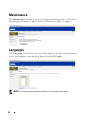
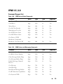
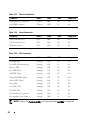
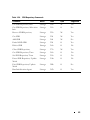
1
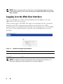
Dell PowerEdge C6105 Using the Baseboard Management Controller COMMENT COMMENT COMMENT COMMENT COMMENT COMMENT COMMENT COMMENT COMMENT COMMENT COMMENT COMMENT COMMENT COMMENT COMMENT ____________________ Information in this publication is subject to change without notice. © 2011 Dell Inc. All rights reserved. Reproduction of these materials in any manner whatsoever without the written permission of Dell Inc. is strictly forbidden. Trademarks used in this text: Dell™, the DELL logo, and PowerEdge™ are trademarks of Dell Inc. Microsoft® and Windows® are registered trademarks of Microsoft Corporation. Linux® is a registered trademark of Red Hat, Inc. in the United States and/or other countries. Other trademarks and trade names may be used in this publication to refer to either the entities claiming the marks and names or their products. Dell Inc. disclaims any proprietary interest in trademarks and trade names other than its own. January 2011 Rev. A00 Contents Introduction . . . . . . . . . . . . . . . . . . . . . . . . . . . . . . . BMC Key Features and Functions . Using the Web UI . . . . . . . . . . . . . . . . . . . 5 . . . . . . . . . . . . . . . . . . . . . . . . . . . . 5 Logging in to the Web User Interface . System Features . 5 . . . . . . . . . . . . . . . . . 6 . . . . . . . . . . . . . . . . . . . . . . . . . . . . 7 System Information. . . Component Information Firmware Update . . . . . . . . . . . . . . . . . . . . . . . . . . 7 8 9 . . . . . . . . . . . . . . . . . . . . . . . 13 . . . . . . . . . . . . . . . . . . . . . . . . . . . Front Panel User Interface . . . . . . . . . . . . . . . . . . . . . . . . . . . . . . . . . . . . . . . . . . . . Power Button. ID Button . . . LEDs . . . . . . . . . . . . . . . . . . . . . . . . . . . . . . . . 13 13 13 System Information . . . . . . . . . . . . . . . . . . . . . . . . . . . 15 . . . . . . . . . . . . . . . . . . . . . . . . . . . . . . . . . . . . . . . . . . . . . . . . . . . 15 15 16 . . . . . . . . . . . . . . . . . . . . . . . . . . . . . . 16 System Information. List FRU . . . . . . . Components . . . . Server Health . . . . . . . . . . . . . . . . . . . . . . . . . . . . . . . . . . . . . . . . . . . . . . . . Sensor Readings . . . . . . . . . . Sensor Readings With Thresholds . Event Log . . . . . . . . . . . . . . Configuration . . . . . . . . . . . . . . . . 17 19 21 . . . . . . . . . . . . . . . . . . . . . . . . . . . . . . 23 Alerts . . . . . Mouse Mode . Network . . . SMTP . . . . . Users . . . . . PEF . . . . . . . . . . . . . . . . . . . . . . . . . . . . . . . . . . . . . . . . . . . . . . . . . . . . . . . . . . . . . . . . . . . . . . . . . . . . . . . . . . . . . . . . . . . . . . . . . . . . . . . . . . . . . . . . . . . . . . . . . . . . . . . . . . . . . . . . . . . . . . . . . . . . . . . . . . . . . . . . . . . . . . . . . . . . . . . . . . . . . . . . . . . . . . . . . . . . . . . . 24 26 27 28 29 32 3 Remote Control . . . . . . . . . . . . . . . . . . . . . . . . . . . . Console Redirection . Server Power Control 33 37 . . . . . . . . . . . . . . . . . . . . . . . . . . . . . 38 Languages . . . . . . . . . . . . . . . . . . . . . . . . . . . . . . . 38 IPMI 1.5 / 2.0 . . . . . . . . . . . . . . . . . . . . . . . . . . . . . . 39 Maintenance. Command Support List . 4 33 . . . . . . . . . . . . . . . . . . . . . . . . . . . . . . . . . . . . . . . . . . . . . . . . . . . . . . . . . . . . . . . . . 39 Introduction This section introduces the Baseboard Management Controller (BMC) and includes the requirements for web-based graphical user interface (GUI), keyboard, video, and mouse (KVM), and virtual media. BMC Key Features and Functions The following lists the supported features of the BMC: • Support for IPMI v1.5 and v2.0 • Out-of-band monitoring and control for server management over LAN • Dedicate NIC for remote management • FRU information report, which includes main board part number, product name, manufacturer, etc. • Health status/hardware monitoring report • View and clear event logs. • Event notification by lighting chassis LED indicator and Platform Event Trap (PET) • Platform Event Filtering (PEF) to take selected action for selected events including NMI • Chassis management, which includes power control, status report, front panel buttons, and LEDs control • Watchdog and auto server re-start and recovery • Support for multi-session user and alert destination for LAN channel Using the Web UI The BMC firmware features an embedded web server, enabling users to connect to the BMC using an Internet browser (Microsoft Internet Explorer) without needing to install KVM and virtual storage software on a remote console. Web-based GUI is supported on the following browsers: Microsoft Windows: • Internet Explorer 6, 7 or later • Mozilla Firefox 2.0 or later Linux: • Mozilla Firefox 2.0 or later 5 NOTE: Before using the web user interface, ensure that the firewall settings are configured to enable access to the following ports: 8890 (KVM), 9000 (storage), 9001, 9002, and 9003. Logging in to the Web User Interface Enter the IP address or URL (default DHCP\static IP address) into the address bar of the web browser. When connecting to the BMC, the login screen prompts for the username and password. This authentication with Secure Sockets Layer (SSL) protection prevents unauthorized intruders from gaining access to the BMC web server. Once authentication is passed, you can manage the server by privilege. Table 1-1. Default User Name And Password Field Default User Name root Password root NOTE: The default username and password are in lowercase characters. It is advised to change the root password once you have logged in. 6 System Features System Information The System Information tab enables you to view the BMC firmware version, BIOS version, and PIC version. Click the System Information tab to view the Remote Management Controller. Table 1-1. BMC Summary BMC Information Description Device Power Status Current power state of the system. Firmware Revision Dell Remote Management Controller firmware version. Aux Firmware Revision Firmware build number. Firmware Build Time Date the firmware was last flashed in the form: MMM Day YYYY HH:MM:SS BMC Chipset Dell Remote Management Controller type. BIOS Version BIOS version for the system. PIC Version PIC FW version for chassis fan control board. 7 Component Information Server Board Information Including Serial Number, BIOS Version, Product ID, Manufacturer, and Manufacture Date. CPU Information Including Socket, Manufacturer, Model, and Frequency. Memory Information Including Memory ID, Status, Socket, Module Size, Model, and Frequency. 8 Firmware Update Use the Firmware Update feature to upgrade to the latest firmware version. The following data is included in the BMC firmware package: • Compiled BMC firmware code and data • Web-based user interface, JPEG, and other user interface data files • Default configuration files Updating the BMC Firmware Through TFTP/HTTP/FTP 1 Get Reservation ID. >ipmitool -H <BMC IP Address> -I lanplus -U root -P root raw 0x30 0x01 > 01 2 Enable Remote Update. >ipmitool -H <BMC IP Address> -I lanplus -U root -P root raw 0x30 0x02 0x01 0x10 0x01 0x00 0x00 0x00 0xff >10 01 00 01 01 3 Get Protocol. >ipmitool -H <BMC IP Address> -I lanplus -U root -P root raw 0x30 0x02 0x01 0x10 0x02 0x00 0x00 0x00 0xff >10 02 00 01 07 4 Set URL. HTTP Server Update: (Ex: http://192.168.1.111/s2gv112.bin) >ipmitool -H <BMC IP Address> -I lanplus -U root -P root raw 0x30 0x03 0x01 0x10 0x03 0x00 0x00 0x00 0x01 0xFF 0x68 0x74 0x74 0x70 0x3A 0x2F 0x2F 0x31 0x39 0x32 0x2E 0x31 0x36 0x38 0x2E 0x31 0x2E 0x31 0x31 0x31 0x2F 0x73 0x32 0x67 0x76 0x31 0x31 0x32 0x2E 0x62 0x69 0x6E ASCII code for URL "http://192.168.1.111/s2gv112.bin" Response: 21 written data length 9 FTP Server Update: (Ex: ftp://user:[email protected]/s2gv112.bin) >ipmitool -H <BMC IP Address> -I lanplus -U root -P root raw 0x30 0x03 0x01 0x10 0x03 0x00 0x00 0x00 0x01 0xFF 0x68 0x74 0x74 0x70 0x3A 0x2F 0x2F 0x31 0x39 0x32 0x2E 0x31 0x36 0x38 0x2E 0x31 0x2E 0x31 0x31 0x31 0x2F 0x73 0x32 0x67 0x76 0x31 0x31 0x32 0x2E 0x62 0x69 0x6E ASCII code for URL "http://192.168.1.111/s2gv112.bin" Response: 21 written data length TFTP Server Update: (Ex: tftp://192.168.1.111/s2gv112.bin) >ipmitool -H <BMC IP Address> -I lanplus -U root -P root raw 0x30 0x03 0x01 0x10 0x03 0x00 0x00 0x00 0x01 0xFF 0x74 0x66 0x74 0x70 0x3A 0x2F 0x2F 0x31 0x39 0x32 0x2E 0x31 0x36 0x38 0x2E 0x31 0x2E 0x31 0x31 0x31 0x2F 0x73 0x32 0x67 0x76 0x31 0x31 0x32 0x2E 0x62 0x69 0x6E ASCII code for URL "tftp://192.168.1.111/s2gv112.bin" Response: 21 written data length Updating BMC Firmware Through Updating Firmware Command >ipmitool -H <BMC IP Address> -I lanplus -U root -P root raw 0x08 0x01 0x01 0x80 0x00 Response: 34 firmware update task ID (force update, config) >ipmitool -H <BMC IP Address> -I lanplus -U root -P root raw 0x08 0x01 0x01 0x80 0x01 Response: 34 firmware update task ID (normal update, no config) >ipmitool -H <BMC IP Address> -I lanplus -U root -P root raw 0x08 0x01 0x01 0x00 0x00 Response: 34 firmware update task ID (normal update, config) >ipmitool -H <BMC IP Address> -I lanplus -U root -P root raw 0x08 0x01 0x01 0x00 0x01 Response: 34 firmware update task ID 1 Get Firmware Status. 10 ipmitool -H <BMC IP Address> -I lanplus -U root -P root raw 0x08 0x02 <Task ID (ex: 0x34)> Response: Status Code as followed: 0x00: Transmitting Image 0x01: Validating Image 0x02: Programming 0x03: Ready to Accept Image 0x04: USB Unit Stage 0x05: Connecting to server 0x80: General Error 0x81: Cannot establish connection 0x82: Path not found 0x83: Transmission Abort 0x84: Checksum Error 0x85: Incorrect Platform 0x86: Allocate memory failed 0x87: Virtual media detach failed 0xFF: Completed 2 Restart firmware while status code is 0xFF >ipmitool -H <BMC IP Address> -I lanplus -U root -P root raw 0x06 0x02 Update BMC Firmware Through UI NOTE: Before beginning the firmware update, download the latest firmware version and save it on your local system. During the process of firmware update, the AC power of the managed system cannot be unplugged and the Web GUI cannot be closed. NOTE: Once you enter into Update Mode and choose to cancel the firmware flash operation, the BMC must be reset. This means that you must close the Internet browser and log back onto the BMC card before you can perform any other types of operations. 11 Select the Enter Update Mode button from the Maintenance tab to put the device in a special mode that allows firmware update. You can now follow the instructions presented below to successfully update the card’s firmware. The device resets if update is cancelled. The device also resets upon successful completion of firmware update. 1 Browse to, or enter the path on your system where the firmware image file resides. Example: C:\Updates\V1.0\<image_name> The default firmware image name is s2gvXXX.bin (XXX means for version number). 2 Select if you want the BMC to auto reset after the update. 3 Click Update Firmware. The update might take several minutes. When the update is completed, a dialog box appears. 4 Click OK to close the session and automatically log out. 5 After the BMC resets, click Log In to log in to the BMC again. Update BMC Firmware Through SSH 1 Get Reservation ID. >ipmitool -H <BMC IP Address> -I lanplus -U root -P root raw 0x30 0x01 > 01Reservation ID 2 Enable SSH/Telnet Service. >ipmitool -H <BMC IP Address> -I lanplus -U root -P root raw 0x30 0x03 <Reservation ID> 0x04 0x01 0x00 0x00 0x00 0x01 0x00 >01 3 Enable SSH/Telnet Redirection: >ipmitool -H <BMC IP Address> -I lanplus -U root -P root raw 0x30 0x03 <Reservation ID> 0x03 0x02 0x00 0x00 0x00 0x01 0x01 >01 12 Front Panel User Interface The BMC provides control panel interface functionality including indicators (fault, status, and ID LEDs) and buttons (power/ID). Power Button The power button turns the device on and off. ID Button The control panel Chassis Identify button toggles the state of the Chassis ID LED. If the ID LED is off, pressing the button turns the LED on (blinking). If the LED is on, pressing the button or an IPMI Chassis Identify command turns the LED off. LEDs BMC Heartbeat LED The green LED provides an easy way to indicate that BMC is now enabled. ID LED A blinking LED indicates the Chassis Identify command has been accepted. System Status LED There is a dual-color LED to show the system status. The BMC turns the LED off after all event logs are cleared. The behavior of Status LED and ID LED is listed in Table 1-2. Table 1-2. LED Status LED Color Status When Status LED Amber Blinks See "Blinking Health LED Conditions" on page 14. Off Normal status On Amber LED is off Blinks Amber LED is blinking Off DC off Green 13 Table 1-2. LED Status (continued) LED Color Status When ID LED Off Normal status Blinks Identifying the system Off BMC is not ready Blinks BMC is ready Heartbeat LED Blue Green Table 1-3. Blinking Health LED Conditions Item Description Temperature Sensors Non-critical / critical event asserted Fan Sensors Non-critical / critical event asserted Voltage Sensors State asserted Power Supply State asserted Processor Thermal trip Event Logging Disable • SEL almost full • SEL full Post Error System firmware error Memory • Correctable ECC error • Uncorrectable ECC error • Correctable ECC error logging limit reached PCI-E Bus • Bus correctable error • Bus uncorrectable error • Bus fatal error Watchdog 2 • Timer expired • Hard reset • Power down • Power cycle 14 System Information System Information The System Information tab shows general information about the system including Device Power Status, Firmware Revision, AuxFirmware Revision, Firmware Build Time, BMC Chipset, BIOS Version, and PIC Version. List FRU The List FRU tab shows a list of the detected Field Replaceable Units (FRUs) in the system. Select a FRU item from the drop down list to show more information. 15 Components The Components tab shows a table of the components. The components can be filtered by category and can be sorted by the column header. The table shows the Socket, Manufacturer, and Model of each component. Server Health The Server Health tab provides information about the server’s health such as sensor readings and the event log. The sensor readings can be shown with or without thresholds in the table. 16 Table 1-1. Server Health Options Button Description Sensor Readings This button allows you to view the readings from the various sensors. Sensor Readings with Thresholds This button allows you to view the readings from the various sensors, with thresholds included in the table. Event Log This button allows you to view the events written to the event log. Sensor Readings The Sensor Readings tab shows all sensor readings from the system. Table 1-2. Sensor Readings Item Description Sensor Type Selection Drop Down Menu This drop down menu allows you to select the type of sensor readings that you want to show in the list. • All Sensors • Voltage Sensors • Current Sensors 17 Table 1-2. Sensor Readings Item Description Sensor Readings List This field shows the individual sensor’s name, reading, and the current status of the sensor. Refresh Button Use this button to refresh the sensor readings view. Show Thresholds Button Clicking Show Thresholds button expands the sensor reading table and also shows the various threshold settings for every sensor. • Name • Status • Reading • Low NR • Low CT • Low NC • High NC • High CT • High NR 18 Sensor Readings With Thresholds The Sensor Readings with Thresholds tab shows all sensor readings and thresholds from the system. Table 1-3. Sensor Readings With Thresholds Item Description Sensor Selection Drop Down Menu This drop-down menu allows you to select the type of sensor readings that you want to show in the list. • All Sensors • Voltage Sensors • Current Sensors Sensor Readings List This field shows the individual sensor’s name, reading and the current status of the sensor. It also shows the following threshold settings for every sensor. • Low NR • Low CT • Low NC • High NC • High CT • High NR Refresh Button Use this button to refresh the sensor readings view. Hide Thresholds Button Clicking Hide Thresholds button reduces the sensor reading table and hides the various threshold settings for every sensor. Table 1-4. Temperature Thresholds Temperature Sensor Number UNCT UCT CPU0_Temp 0x44 75 78 CPU1_Temp 0x45 75 78 MB_TEMP 0x40 60 65 NB_TEMP 0x41 95 98 P0_DIMM_TEMP 0x4C 96 98 19 Table 1-4. Table Temperature Thresholds (continued) Temperature Sensor Number UNCT UCT P1_DIMM_TEMP 0x4D 96 98 Chassis_Ambient 0x54 48 50 Outlet_TEMP 0x42 N/A N/A Table 1-5. Voltage Thresholds Voltage Sensor Sensor Number Normal LCT LNCT UNCT UCT CPU_0_Vcore 0x10 1.00V N/A N/A N/A N/A CPU_1_Vcore 0x11 1.00V N/A N/A N/A N/A DDRP0_Voltage 0x12 1.5V 1.349V 1.388V 1.599V 1.646V DDRP1_Voltage 0x13 1.5V 1.349V 1.388V 1.599V 1.646V DDRP0_Voltage (LV) 0x12 1.35V 1.209V 1.248V 1.443V 1.482V DDRP1_Voltage (LV) 0x13 1.35V 1.209V 1.248V 1.443V 1.482V P5V 0x28 5V 4.472V 4.628V 5.330V 5.486V P3V3 0x15 3.3V 2.958V 3.062V 3.526V 3.629V Table 1-6. Current Thresholds Current Sensor Sensor Number LCT LNCT UNCT UCT MB_12V_Current 0xCA N/A N/A N/A N/A PSU1_OUT_Current 0x70 N/A N/A N/A N/A PSU2_OUT_Current 0x71 N/A N/A N/A N/A Table 1-7. Fan Thresholds Fan Sensor Sensor Number LCT LNCT UNCT UCT FCB Fan 1 0x6B 1000 1200 N/A N/A FCB Fan 2 0x6C 1000 1200 N/A N/A FCB Fan 3 0x6D 1000 1200 N/A N/A FCB Fan 4 0x6E 1000 1200 N/A N/A 20 Event Log The Event Log tab shows a table of the events from the system's event log. Table 1-8. Event Log Item Description Select An Event Log Category Select one of the following event categories: • Sensor-Specific Events • BIOS-Generated Events • System Management Software Events Event Log You can obtain the following information for each event: • Event ID • Time Stamp • Sensor Name • Sensor Type • Description Clear Event Log Button Click the Clear Event Log button to clear the event logs. 21 Table 1-9. Blinking Health LED Conditions Item Description Temperature Sensors Non-critical / critical event asserted Fan Sensors Non-critical / critical event asserted Voltage Sensors State asserted Power Supply State asserted Processor Thermal trip Event Logging Disable • SEL almost full • SEL full Post Error System firmware error Memory • Correctable ECC error • Uncorrectable ECC error • Correctable ECC error logging limit reached PCI-E Bus • Bus correctable error • Bus uncorrectable error • Bus fatal error Watchdog 2 • Timer expired • Hard reset • Power down • Power cycle 22 Configuration The Configuration tab allows you to access various configuration settings including Alerts, Mouse Mode, Network, SMTP, Users, and PEF. Table 1-10. Configuration Options Button Description Alerts Button This button takes you to the Alert list tab, where you can add, edit or remove alert destinations. Mouse Mode Button This button takes you to the Mouse Mode settings tab, where you can view the current setting and/or change the mode of your pointing device to/from either Relative or Absolute. Network Button This button takes you to the Network settings tab, where you can view the MAC address or change network settings, including the dynamic and static IP assignment. SMTP This button takes you to the SMTP settings tab, where you can configure the SMTP mail server. Users This button takes you to the user list tab, where you can add, edit or remove users. PEF This button takes you to the PEF list tab, where you can configure PEF settings including Event Filter Action, Alert Policy Number, Sensor Type, Event Severity, and Event Trigger. 23 Alerts On the Alerts tab, you can configure alert destinations. To delete an alert, select it and press Delete. To create a new alert, select a destination address that has not been configured, yet, from the alert table entry and click Modify. To send a test alert, select the alert from the list and click the Send Test Alert button. Table 1-11. List of Alerts Item Description Modify Button Use this button to modify an alert. Send Test Alert Button Use this button to send a test alert. Delete Button Use this button to delete an alert. 24 Table 1-12. Modify Alert Item Description Alert Type You can select the way an alert is sent when it is triggered by an event. • SNMP Trap • Email Destination IP Type the SNMP destination IP address into this field. If Email as Alert Type is selected, the field is grayed out. Email Address Type the email address into this field. If SNMP Trap as the Alert Type is selected, the field is grayed out. Subject Type a subject into this field. If SNMP Trap as the Alert Type is selected, the field is grayed out. Message Type a message into this field. If SNMP Trap as the Alert Type is selected, the field is grayed out. Save Button Use this button to save your settings. Cancel Button Use this button to cancel this action. 25 Mouse Mode On the Mouse Mode tab, you can configure the mouse mode options. Table 1-13. Mouse Mode Item Description Set Mode to Absolute Option Select this option to select mouse mode to Absolute, depending upon your system. This mode enables you to see two mouse cursors where, one is the redirected host mouse cursor and the other is the actual local mouse cursor. It is recommended to use this mode when the host server is running in the Windows platform. Set Mode to Relative Option Select this option to select mouse mode to Relative, depending upon your system. In this mode, the user can see only one mouse cursor that is redirected. This mode locks the local mouse cursor inside the redirected window and the user has to press <Alt+M> to unlock and stop mouse redirection. Here <Alt+M> is basically used to start or stop mouse redirection. It is recommended to use this mouse mode when the host server is running in Linux and other OS platforms. Apply Button Use this button to make the settings active. 26 Network The Network tab allows you to view and modify the network settings. Select whether to obtain an IP address automatically or manually configure one. Table 1-14. Network Item Description LOM Port Number The default is share NIC and the port is LOM 1. MAC Address This field shows the MAC address. Obtain an IP address This option allows the BMC’s IP to be configured by a DHCP automatically (use DHCP) server (dynamically). Use the following IP address This option allows you to configure a static IP. The IP Address, Subnet Mask, and Gateway fields become editable when this option is selected. IP Address This field allows you to set the BMC’s IP address. Subnet Mask This field allows you to set the Subnet Mask. Default Gateway This field allows you to set the BMC’s Gateway access address. Save Button Use this button to save your settings. 27 SMTP The SMTP tab allows you to configure the SMTP mail server. Table 1-15. Modify SMTP Item Description Mail Server IP This field allows you to configure the IP address of the SMTP mail server. Save Button Use this button to save your settings. NOTE: To test the SMTP server, use the Send Test Alert button on the Alerts tab. 28 Users The Users tab allows you to view the current list of user for the server. If you would like to delete or modify a user, select their name in the list and click Delete User or Modify User. To add a new user, select an un-configured slot and select Add User. Table 1-16. User List Item Description UserID Column This column shows the ID number used in association with the User Name. User Name Column This column shows a list of all users who are able to access this BMC. NOTE: The default administrator is root. It is prudent for you to change the root password. Network Privilege Column This column shows the network rights associated with the account. Add User Button Use this button to add a new user. Select an open field first. Modify User Button Use this button to modify an existing user. Select a user first. 29 Table 1-16. User List Item Description Delete User Button Use this button to delete an existing user. Select a user first. Table 1-17. Add New User Item Description User Name Enter a user name in the user name field. Your user name must be at least four characters long and no more than 32 characters long. User names are case-sensitive and must start with an alphabetical character. Password Enter a password in the password field. Your password must be at least eight characters long. NOTE: The password must be a minimum of eight characters and a maximum of 32 characters. Use a combination of alphanumeric and special characters for better security. The password is case-sensitive. Confirm Password Confirm your password by entering your password again in the Confirm Password field. Network Privileges Drop Assign network permissions and access rights to any of the Down Menu following: • Administrator • Operator • User • Callback • OEM • No Access Add Button Use this button to add the new user. Cancel Button Use this button to cancel this action. 30 Table 1-18. Modify User Item Description User Name This field contains the user name being modified. This field cannot be modified. Change Password Box Select this box to change the password. Password Enter the new password in the password field. Your password must be at least eight characters long. NOTE: The password must be a minimum of eight characters and a maximum of 32 characters. Use a combination of alphanumeric and special characters for better security. The password is case-sensitive. Confirm Password Confirm your password by entering your password again in the Confirm Password field. Network Privileges Drop Modify network permissions and access rights to any of the Down Menu following: • Administrator • Operator • User • Callback • No Access Modify Button Use this button to update the user account. Cancel Button Use this button to cancel this action. 31 PEF The PEF tab allows you to view the list of the configured PEF destinations. You can select a PEF and press the Modify button to configure it. Table 1-19. PEF Item Description Event Filter Action Specify the corresponding action for a PEF triggered event. Alert Policy Number Specify the policy number (default: 1) for the alert policy. Sensor Type Specify the sensor type (default: No Sensor Type) to trigger PEF action. Event Severity Specify severity level of event to trigger PEF action (default: Unspecified) Event Trigger Specify threshold to trigger PEF action. Any: for any event trigger. Select: specify a specific event. 32 Remote Control The Remote Control tab allows you to initiate Console Redirection and to view the Power Control options. Console Redirection The Console Redirection tab enables you to use the display, mouse, and keyboard on the local management station to control the corresponding devices on a remote managed system. Click on Launch Console to launch the Java-based remote console. System Requirements • JRE 1.5 or later • Windows OS • Linux OS (Red Hat Enterprise Linux 5.X 32/64 bit, Ubuntu Desktop Edition 10.X 32/64 bit, Fedora Core 8 or later) • Internet Explorer 6 or later • Firefox 2.x, 3.x • Safari 5.0.1 33 Table 1-20. Console Redirection Buttons Item Description Console Redirection Use this button to launch the redirection console using Java viewer. Power Control Use this button to view the power state and perform power control functions on the server. Table 1-21. Remote Console Shortcut Key Combinations Keystroke Description <ALT+S> Start Console Redirection <ALT+T> Stop Console Redirection <ALT+R> Restart Console Redirection <ALT+F> Toggle Full Screen Mode <ALT+M> Synchronize Mouse <ALT+A> Hold/Unhold Right <ALT> Key <ALT+B> Hold/Unhold Left <ALT> Key <ALT+L> Hold/Unhold Right <CTRL> Key <ALT+N> Hold/Unhold Left <CTRL> Key <ALT+D> Generate <CTRL>, <ALT>, + <DEL> <ALT+E> Start CD-ROM Drive Redirection 34 Table 1-22. Console Redirection Window: Keyboard Menu Item Description Hold Right Ctrl Key This menu item can be used to act as the right-side <CTRL> key when in Console Redirection. Hold Right Alt Key This menu item can be used to act as the right-side <ALT> key when in Console Redirection. Hold Left Ctrl Key This menu item can be used to act as the left-side <CTRL> key when in Console Redirection. Hold Left Alt Key This menu item can be used to act as the left-side <ALT> key when in Console Redirection. Left Windows Key This menu item can be used to act as the left-side <WIN> key when in Console Redirection. You can also decide how the key should be pressed: • Hold Down • Press and Release Right Windows Key This menu item can be used to act as the right-side <WIN> key when in Console Redirection. You can also decide how the key should be pressed: • Hold Down • Press and Release <Alt+Ctrl+Del> Table 1-23. This menu item can be used to act as if you pressed the <CTRL>, <ALT> and <DEL> keys down simultaneously on the server that you are redirecting. Console Redirection Window: Mouse Menu Item Description Sync Cursor This menu item can be used to synchronize or unsynchronize the mouse cursor. Show Cursor This menu item can be used to show or hide the local mouse cursor on the remote client system. 35 Table 1-24. Console Redirection Window: Options Item Description Bandwidth The bandwidth usage option allows you to adjust the bandwidth. You can select one of the following: • Auto Detect • 256 Kbps • 512 Kbps • 1 Mbps • 10 Mbps • 100 Mbps (Default Setting) KB/Mouse Encryption This option allows you to encrypt keyboard inputs and mouse movements sent between the connections. Table 1-25. Console Redirection Window: Device Menu Item Description Redirect CDROM This menu item can be used to start or stop the redirection of a physical DVD/CD-ROM drive. Redirect ISO This menu item can be used to start or stop the redirection of a DVD/CD ISO image. Redirect Floppy/USB Key This menu item can be used to start or stop the redirection of a physical floppy/USB key drive. Redirect Floppy/USB Key Image This menu item can be used to start or stop the redirection of a floppy/USB key image, instead of a physical driver. Table 1-26. Console Redirection Window: Help Menu Item Description About JViewer Shows the copyright and version information. 36 Server Power Control The Server Power Control tab allows you to view and control the power of your server. Select one of the options listed in the following table to execute on your server. You are asked to confirm your choice. Upon confirmation, the command is executed and you are informed of the status. Table 1-27. Power Control and Status Menu Item Description Reset Server Option Select this option to reset the server. Power Off Server Immediate Option Select this option to power down the server immediately. Power Off Server Orderly Shutdown Option Select this option to power down the server gracefully. Power On Server Option Select this option to power up the server. Power Cycle Server Option Select this option to power cycle the server. Perform Action Button Select this button to execute the option selected. 37 Maintenance The Maintenance tab allows you to perform maintenance tasks on the device including the Firmware Update. Refer to "Firmware Update" on page 9. Languages The Languages tab allows you to select the language for the web application. Select the language from the drop down list and click Apply. NOTE: The web interface needs to reload for the change to take effect. 38 IPMI 1.5 / 2.0 Command Support List Table 1-28. IPMI Device Global Commands Command NetFn CMD O/M Supported Get Device ID App 01h M Yes Cold Reset App 02h O Yes Warm Reset App 03h O No Get Self Test Results App 04h M Yes Manufacture Test On App 05h O Yes Set ACPI Power State App 06h O Yes Get ACPI Power State App 07h O Yes Get Device GUID App 08h O Yes App 01h M Yes Broadcast Commands: Broadcast ‘Get Device ID’ Table 1-29. BMC Device and Messaging Commands Command NetFn CMD O/M Supported Set BMC Global Enables App 2Eh M Yes Get BMC Global Enables App 2Fh M Yes Clear Message Buffer Flags App 30h M Yes Get Message Buffer Flags App 31h M Yes Enable Message Channel Receive App 32h O Yes Get Message App 33h M Yes Send Message App 34h M Yes Read Event Message Buffer App 35h O Yes Get BT Interface Capabilities App 36h M No Get System GUID App 37h M Yes 39 Table 1-29. BMC Device and Messaging Commands Command NetFn CMD O/M Supported Get Channel Authentication Capabilities App 38h M Yes Get Session Challenge App 39h M Yes Activate Session Command App 3Ah M Yes Set Session Privilege Level Command App 3Bh M Yes Close Session App 3Ch M Yes Get Session Information App 3Dh M Yes Get Authentication Code Command App 3Fh O Yes Set Channel Access Commands App 40h M Yes Get Channel Access Commands App 41h M Yes Get Channel Info Command App 42h M Yes Set User Access Commands App 43h M Yes Get User Access Commands App 44h M Yes Set User Name Commands App 45h M Yes Get User Name Commands App 46h M Yes Set User Password Commands App 47h M Yes Active Payload Command App 48h M Yes Deactivate Payload Command App 49h M Yes Get Payload Activation Status App 4Ah M Yes Get Payload Instance Info Command App 4Bh M Yes Set User Payload Access App 4Ch M Yes Get User Payload Access App 4Eh M Yes Get Channel Payload Support App 4Fh M Yes Get Channel Payload Version App 50h M Yes Master Write-Read I2C App 52h M Yes 40 Table 1-29. BMC Device and Messaging Commands Command NetFn CMD O/M Supported Get Channel Cipher Suites App 54h O Yes Suspend/Resume Payload Encryption App 55h O Yes Set Channel Security Keys App 56h O Yes Get System Interface Capabilities App 57h O No Table 1-30. BMC Watchdog Timer Commands Command NetFn CMD O/M Supported Reset Watchdog Timer App 22h M Yes Set Watchdog Timer App 24h M Yes Get Watchdog Timer App 25h M Yes Command NetFn CMD O/M Supported Get Chassis Capabilities Chassis 00h M Yes Get Chassis Status Chassis 01h M Yes Chassis Control Chassis 02h M Yes Chassis Reset Chassis 03h O No Chassis Identify Chassis 04h O Yes Set Chassis Capabilities Chassis 05h O Yes Set Power Restore Policy Chassis 06h O Yes Get System Reset Cause Chassis 07h M Yes Set System Boot Options Chassis 08h M Yes Get System Boot Options Chassis 09h M Yes Set Front Panel Button Enable Chassis 0Ah M Yes Table 1-31. Chassis Commands 41 Table 1-31. Chassis Commands Command NetFn CMD O/M Supported Set Power Cycle Interval Chassis 0Bh M Yes Get POH Counter Chassis 0Fh O No Command NetFn CMD O/M Supported Set Event Receiver S/E 00h M M Get Event Receiver S/E 01h M M Platform Event S/E 02h M M Command NetFn CMD O/M Supported Get SEL Info Storage 40h M Yes Get SEL Allocation Info Storage 41h O No Reserve SEL Storage 42h O Yes Get SEL Entry Storage 43h M Yes Add SEL Entry Storage 44h M Yes Partial Add SEL Entry Storage 45h M No1 Delete SEL Entry Storage 46h O Yes Clear SEL Storage 47h M Yes Get SEL Time Storage 48h M Yes Set SEL Time Storage 49h M Yes Get Auxiliary Log Status Storage 5Ah O No Set Auxiliary Log Status Storage 5Bh O No Table 1-32. Event Commands Table 1-33. SEL Commands NOTE: Support for Partial Add SEL is not required when Add SEL is supported. 42 Table 1-34. SDR Repository Commands Command NetFn CMD O/M Supported Get SDR Repository Info Storage 20h M Yes Get SDR Repository Allocation Info Storage 21h O No Reserve SDR Repository Storage 22h M Yes Get SDR Storage 23h M Yes Add SDR Storage 24h M No Partial ADD SDR Storage 25h O Yes Delete SDR Storage 26h O No Clear SDR Repository Storage 27h M Yes Get SDR Repository Time Storage 28h O Yes Set SDR Repository Time Storage 29h O Yes Enter SDR Repository Update Mode Storage 2Ah O No Exit SDR Repository Update Mode Storage 2Bh O No Run Initialization Agent Storage 2Ch O Yes 43 Table 1-35. FRU Inventory Device Commands Command NetFn CMD O/M Supported Get FRU Inventory Area Info Storage 10h M Yes Read FRU Inventory Data Storage 11h M Yes Write FRU Inventory Data Storage 12h M Yes Table 1-36. Sensory Device Commands Command NetFn CMD O/M Supported Get Device SDR Info S/E 20h O No Get Device SDR S/E 21h O No Reserve Device SDR Repository S/E 22h O No Get Sensor Reading Factors S/E 23h O Yes Set Sensor Hysteresis S/E 24h O Yes Get Sensor Hysteresis S/E 25h O Yes Set Sensor Threshold S/E 26h O Yes Get Sensor Threshold S/E 27h O Yes Set Sensor Event Enable S/E 28h O Yes Get Sensor Event Enable S/E 29h O Yes Re-arm Sensor Events S/E 2Ah O Yes Get Sensor Event Status S/E 2Bh O Yes Get Sensor Reading S/E 2Ch M Yes Set Sensor Type S/E 2Dh O No Get Sensor Type S/E 2Eh O No Set Sensor Reading and Event Status S/E 2Fh M Yes 44 Table 1-37. LAN Commands Command NetFn CMD O/M Supported Set LAN Configuration Parameters (Note: Parameter 9 and 25 are not supported.) Transport 01h M Yes Get LAN Configuration Parameters (Note: Parameter 9 and 25 are not supported.) Transport 02h M Yes Suspend BMC ARP Transport 03h O No Get IP/UDP/RMCP Statistics Transport 04h O No Table 1-38. PEF/PET Alerting Commands Command NetFn CMD O/M Supported Get PEF Capabilities S/E 10h M Yes Arm PEF Postpone Timer S/E 11h M Yes Set PEF Configuration Parameters S/E 12h M Yes Get PEF Configuration Parameters S/E 13h M Yes Set Last Processed Event ID S/E 14h M Yes Get Last Processed Event ID S/E 15h M Yes Alert Immediate S/E 16h M Yes PET Acknowledge S/E 17h M Yes VLAN Configuration The VLAN is confiugred through the IPMI Set/Get LAN Configuration command. To configure the VLAN: 1 Get VLAN ID : >ipmitool -H <BMC IP Address> -I lanplus -U root -P root raw 0x0C 0x02 0x01 0x14 0x00 0x00 45 >11 00 00 VLAN is disabled/VLAN ID is zero. 2 Enable and Set VLAN ID : >ipmitool -H <BMC IP Address> -I lanplus -U root -P root raw 0x0C 0x01 0x01 0x14 0x02 0x80 3 Disable VLAN ID : >ipmitool -H <BMC IP Address> -I lanplus -U root -P root raw 0x0C 0x01 0x01 0x14 0x00 0x00 BMC Version Information The BMC firmware version can be obtained by using the IPMI - Get Device ID command. To get the BMC firmware version: >ipmitool -H <BMC IP Address> -I lanplus -U root -P root raw 0x06 0x01 >20 01 01 16 02 bf 4c 1c 00 47 32 11 76 00 00 Version 1.16 BIOS Firmware Information The BIOS firmware version can be obtained by using the IPMI - Get Device ID command. To get the BIOS firmware version: > ipmitool -H <BMC IP Address> -I lanplus -U root -P root raw 0x30 0x1e > 53 32 47 5F 33 41 31 35 00 00 Present with ASCII Code : S2G_3A15 46