1
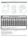
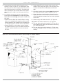
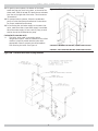
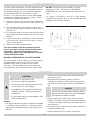
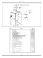
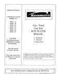
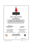
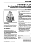
PLYMOUTH STEAM SERIES 2 GAS-FIRED STEAM BOILERS INSTALLATION, OPERATION & MAINTENANCE MANUAL MODEL PVSB Continuous Pilot MODEL PSB Electronic Intermittent Ignition H ECR International, Inc. An ISO 9001-2008 Certified Company 2201 Dwyer Avenue, Utica NY 13504-4729 www.ecrinternational.com P/N# 14683003, Rev. A [07/2011] TABLE OF CONTENTS Safety Symbols .............................................................................................................. 3 Boiler Ratings And Capacities ........................................................................................... 4 Before You Start ............................................................................................................. 5 Locating The Boiler ......................................................................................................... 5 Fresh Air For Combustion................................................................................................. 6 Installation - System Piping ............................................................................................. 7 Chimney And Vent Pipe Connection ................................................................................. 10 Vent Damper Operation ................................................................................................. 11 Gas Supply Piping ......................................................................................................... 12 Electrical Wiring ........................................................................................................... 14 Controls And Accessories ............................................................................................... 20 Operating Instructions................................................................................................... 22 Intermittent Ignition Boiler - VR8204A/VR8304M Gas Valve Operating Instructions................ 22 Continuous Pilot Boiler - VR8200A/VR8300A Gas Valve Operating Instructions ...................... 23 Operating Instructions................................................................................................... 24 Checking and Adjusting ................................................................................................. 25 Cleaning Your Boiler ...................................................................................................... 27 Maintaining Your Boiler .................................................................................................. 28 Service Hints ............................................................................................................... 30 Repair Parts ................................................................................................................. 31 KEEP THIS MANUAL NEAR BOILER RETAIN FOR FUTURE REFERENCE SERIES 2 GAS FIRED BOILERS STEAM BOILERS H 2 SAFETY SYMBOLS The following defined symbols are used throughout this manual to notify the reader of potential hazards of varying risk levels. READ ALL INSTRUCTIONS BEFORE INSTALLING. WARNING DANGER ! Keep boiler area clear and free from combustible materials, gasoline and other flammable vapors and liquids. Indicates a hazardous situation which, if not avoided, WILL result in death or serious injury. DO NOT obstruct air openings to the boiler room. WARNING ! Indicates a hazardous situation which, if not avoided, could result in death or serious injury. ! CAUTION ! Modification, substitution or elimination of factory equipped, supplied or specified components may result in property damage, personal injury or the loss of life. To the owner: Installation and service of this boiler must be performed by a qualified installer. Indicates a hazardous situation which, if not avoided, may result in minor or moderate injury. To the installer: Leave all instructions with the boiler for future reference. NOTICE When this product is installed in the Commonwealth of Massachusetts the installation must be performed by a Licensed Plumber or Licensed Gas Fitter. Indicates information which should be followed to ensure proper installation and operation. WARNING ! 3 All installations of boilers and venting should be done only by a qualified expert and in accordance with the appropriate Installation, Operation and Maintenance manual. Installing or venting a boiler or any other gas appliance with improper methods or materials may result in serious injury or death due to fire or to asphyxiation from poisonous gases such as carbon monoxide which is odorless and invisible. BOILER RATINGS AND CAPACITIES Figure 1 - Dimensions Table 1 - Ratings and Capacities BOILER MODEL NUMBER †Natural Gas (1) †Propane Gas Dimensions (Inches) Input *MBH Heating Capacity *MBH Net I=B-R Rating *MBH Net I=B=R Rating Sq. Ft. Input *MBH Heating Capacity *MBH Net I=B=R Rating *MBH Net I=B=R Rating Sq. Ft. Radiation Flue Diameter "A" Width 3 75 62 47 196 70 58 44 183 5 11¼ PVSB-4D 4 112.5 91 68 283 105 85 64 267 6 14½ PSB-5D PVSB-5D 5 150 122 92 383 140 114 86 358 6 17¾ PSB-6D PVSB-6D 6 187.5 153 115 479 175 143 107 446 7 21 PSB-7D PVSB-7D 7 225 183 137 571 210 171 128 533 7 24¼ PSB-8D PVSB-8D 8 262.5 214 161 671 245 200 150 625 7 27½ PSB-9D PVSB-9D 9 299 245 184 767 280 229 172 717 7 30¾ Intermittent Ignition w/ Vent Damper Standing Pilot w/Vent Damper No. of Sections PSB-3D PVSB-3D PSB-4D * MBH = 1,000 Btuh. Btuh = British Thermal Unit Per Hour. ** Add 5½" to height for Vent Damper † For altitudes above 2,000 ft. reduce input rate 4% for each 1,000 ft. above sea level. Heating Capacity is based on DOE (Department of Energy) test procedure. (1) Add model number suffix 'P' for Propane Gas. The net I=B=R steam Ratings shown are based on a piping and pickup allowance of 1.333. Specifications and dimensions are subject to change without notice. Base selection of boiler size on "Net I=B=R Rating" being equal to or greater than installed radiation in square feet. Consult manufacturer before selecting a boiler for installations having unusual piping and pickup requirements,such as intermittent system operation, exhaust piping systems, etc. 4 BEFORE YOU START Check to be sure you have the right size boiler before starting the installation. See rating and capacity table on previous page. Also be sure the new boiler is for the type of gas you are using. Check the rating plate on the right side of the boiler. You must see that the boiler is supplied with the correct type of gas, fresh air for combustion, and a suitable electrical supply. Also, the boiler must be connected to a suitable venting system and an adequate piping system. Finally, a thermostat, properly located, is needed for control of the heating system. If you have any doubts as to the various requirements, check with local authorities and obtain professional help where needed. Take the time to complete all of the steps for SAFE and PROPER operation of the heating system. If this boiler is installed in a building under construction, special care must be taken to insure a clean combustion air supply during the construction process. Airborne particulates such as from drywall dust and from fiberglass insulation can clog the burner ports and cause incomplete combustion and sooting. These boilers are designed for use in closed heating systems where all of the steam is returned to the boiler as condensate and the amount of make-up water required is minimal. These boilers are not designed for or intended for use in open systems of process applications using 100% make-up water. Damage to the boiler resulting from such use shall not be covered under the warranty. Where required by the authority having jurisdiction, the installation must conform to the Standard for Controls and Safety Devices for Automatically fired Boilers, ANSI/ASME CSD-1. The installation must conform to the requirements of the authority having jurisdiction or, in the absence of such requirements, to the National Fuel Gas Code, ANSI Z223.1/NFPA 54. The following steps are all necessary for proper installation and safe operation of your boiler. 1. LOCATING THE BOILER 5. GAS SUPPLY PIPING 2. FRESH AIR FOR COMBUSTION 6. ELECTRICAL WIRING 3. INSTALLATION - SYSTEM PIPING 7. CHECKING & ADJUSTING 4. CHIMNEY & VENT PIPE CONNECTION LOCATING THE BOILER 1. Select level location as centralized with piping system, and as near chimney as possible. Table - 2 2. Place crated boiler at selected location, remove crate 3. 4. 5. 6. by pulling crate sides from top and bottom boards. Combustible floors: When boiler is to be installed on a combustible floor, a Special Base Plate must be used 146-14-031 (2-6 Section) or 146-14-032 (7-9 Section). This boiler must not be installed on carpeting. Boiler is to be level. Metal shims may be used under base legs for final leveling. Equipment shall be installed in a location in which the facilities for ventilation permit satisfactory combustion of gas, proper venting, and maintenance of ambient temperature at safe limits under normal conditions of use. Equipment shall be located so as not to interfere with proper circulation of air. When normal infiltration does not provide the necessary air, outside air shall be introduced (See Page 6 - “Fresh Air for Combustion”). Advise owner to keep air passages free of obstructions. Ventilating and combustion air must enter boiler room without restrictions. The boiler shall be installed such that the automatic gas ignition system components are protected from water (dripping, spraying, rain, etc.) during appliance operation and service (condensate trap, control replacement, etc.). Minimum Clearance Dimensions Top 6" Rear 6" Control Side 7" Opposite Side 6" Front Alcove Flue/Vent Connector 6" Near Boiler Piping 1" Unit must be set on a concrete or other non-combustible material base or floor. 5 FRESH AIR FOR COMBUSTION B. Known Air Infiltration Rate. See Table 1 for space with boiler only. Use equation for multiple appliances. Do not use an air infiltration rate (ACH) greater than 0.60. WARNING ! Air openings to combustion area must not be obstructed. Following instructions below, adequate combustion air can be maintained. Volume ≥ 21 ft3⁄ACH x Total Input [Mbh] Provide combustion air and ventilation air in accordance with the section “Air for Combustion and Ventilation,” of the National Fuel Gas Code, ANSI Z223.1 / NFPA 54, or applicable provisions of local building codes. C. Refer to National Fuel Gas Code for opening requirements between connected indoor spaces. • All Outdoor Air. Provide permanent opening(s) communicating directly or by ducts with outdoors. Provide make-up air where exhaust fans, clothes dryers, and kitchen ventilation equipment interfere with proper operation. A. Two Permanent Opening Method. Provide opening commencing within 12 inches of top and second opening commencing within 12 inches of bottom of enclosure. National Fuel Gas Code recognizes several methods of obtaining adequate ventilation and combustion air. Requirements of the authority having jurisdiction may override these methods. Direct communication with outdoors or communicating through vertical ducts. Provide minimum free area of 1 in² per 4 Mbh of total input rating of all appliances in enclosure. • Engineered Installations. Must be approved by authority having jurisdiction. • Mechanical Air Supply. Provide minimum of 0.35 cfm per Mbh for all appliances located within space. Additional requirements where exhaust fans installed. Interlock each appliance to mechanical air supply system to prevent main burner operation when mechanical air supply system not operating. Communicating through horizontal ducts. Provide minimum free area of 1 in² per 2 Mbh of total input rating of all appliances in enclosure. B. One Permanent Opening Method. Provide opening commencing within 12 inches of top of enclosure. Provide minimum clearance of 1 inch on sides/back and 6 inches on front of boiler (does not supersede clearance to combustible materials). • All Indoor Air. Calculate minimum volume for all appliances in space. Use a different method if minimum volume not available. A. Standard Method. Cannot be used if known air infiltration rate is 0.40 air changes per hour. See Table 1 for space with natural gas boiler only. Use equation for multiple appliances and/or propane. C. Refer to National Fuel Gas Code for additional requirements for louvers, grilles, screens and air ducts. • Combination Indoor and Outdoor Air. Refer to National Fuel Gas Code for application information. Volume ≥ 50 ft3 x Total Input [Mbh] Table 3 - Minimum Room Volume, Indoor Air Only* Known Air Infiltration Rate Method (Air Changes Per Hour) Standard Input Mbh Method 0.1 0.2 0.3 0.4 0.5 0.6 75 3750 15750 7875 5250 3938 3150 2625 112.5 5625 23625 11813 7875 5906 4725 3938 150 7500 31500 15750 10500 7875 6300 5250 187 9350 39270 19635 13090 9818 7854 6545 255 11250 47250 23625 15750 11813 9450 7875 262.5 13125 55125 27563 18375 13781 11025 9188 299 14950 62790 31395 20930 15698 12558 10465 * Table values based on boiler only. Add volume for any additional appliances. 6 INSTALLATION - SYSTEM PIPING • Use pipe suitable for temperatures of 375°F (191°C) or greater. WARNING ! Burn and scald hazard. Safety valve could discharge steam or hot water during operation. Install discharge piping per these instructions • Individual boiler discharge piping shall be independent of other discharge piping. • Size and arrange discharge piping to avoid reducing safety valve relieving capacity below minimum relief valve capacity stated on rating plate. Near boiler piping, that is the piping around boiler, must be considered as part of boiler for proper water level control, and to produce dry steam. Correct near boiler piping is crucial to the proper operation of the boiler and the heating system. Follow these recommendations carefully. 1. Place boiler in selected location, as near chimney as possible. 2. Install safety valve, using furnished 3/4” coupling, into 3/4” pipe nipple on top of boiler. • Install safety valve with spindle in vertical position. • Run pipe as short and straight as possible to location protecting user from scalding and properly drain piping. • Install union, if used, close to safety valve outlet. • Install elbow(s), if used, close to safety valve outlet and downstream of union (if used). • Terminate pipe with plain end (not threaded). 3. This boiler is equipped with two 2-1/2” supply connections and two 2-1/2” return connections, one each on both the left and right sides of the boiler. Unused connections must be plugged with the 2-1/2” plugs (furnished). • Do no install shutoff valve between boiler and safety valve. • Install discharge piping from safety valve. See Figure 2. • Use 3/4" or larger pipe. Figure 2 - Recommended Near Boiler Piping Using One Supply Tapping 7 INSTALLATION - SYSTEM PIPING 4. Recommended near boiler piping for gravity return 6. System takeoffs from the header must never be bull- systems is shown in Figure 5. This configuration uses one supply and one return tapping. This setup can be used on any size boiler in this series. The supply and return connections may be piped both into the same side (either left or right) or one into each side of the boiler. 5. For installers choosing to use both supply tappings, Figure 6A shows the correct way to pipe this system. Figure 6B shows the wrong way to pipe a header with two risers. • Headers must be fitted with header offsets or swing joints, or be equipped with expansion joints, so that thermal expansion and contraction of the header will not damage the boiler. Headers shall not be welded. headed. If the steam main goes in two directions, there must be two takeoffs from the header, one for each main. 7. All boilers in gravity return systems must be equipped with a Hartford Loop as shown in Figures 2 and 3A. 8. When piping the vertical risers from the boiler to the header, the bottom of the header must be a minimum of 24 inches above the water level line on the right side of the boiler. 9. Steam riser(s) and header shall be 2-1/2” pipe size. 10. Equalizer line shall be minimum 1-1/2” pipe size. 11. The near boiler piping shall include a 2-1/2” tee with a plug located on the supply line as shown for skimming (i.e. surface blowdown). 12. The near boiler piping shall include a 1-1/2 ball valve in the return piping as shown for bottom blowdown and draining. • System takeoffs from the header must be between the equalizer and the riser to the header nearest the equalizer. System takeoffs must never be between two risers. Figure 3A - Recommended Near Boiler Piping Using One Supply Tapping 8 INSTALLATION - SYSTEM PIPING 13. For gravity return systems, the bottom of the lowest Figure 4 - Chilled Water Piping FOR USE WITH COOLING UNITS A. The boiler, when used in connection with a refrigeration system, must be installed so the chilled medium is piped in parallel with the boiler with appropriate valves to prevent the chilled medium from entering the boiler. See Figure 4. VALVES A & B OPEN FOR HEATING; CLOSE FOR COOLING steam carrying pipe, be it a dry return, or the end of the steam main, must be at least 28” above the normal water level line on the right side of the boiler. This is known as “Dimension A.” 14. For pumped return systems, follow the condensate pump or boiler feed pump manufacturer’s instructions for proper installation and hookup. 15. In connecting the cold water supply to the water inlet valve, make sure that a clean water supply is available. When the water supply is from a well or pump, a sand strainer should be installed at the pump. VALVES C & D CLOSE FOR HEATING; OPEN FOR COOLING Figure 3B - Common Near Boiler Piping Mistakes 9 CHIMNEY AND VENT PIPE CONNECTION 8. Do not connect to fireplace flue. 9. End of vent pipe must be flush with inside face of For boilers for connection to gas vents or chimneys, vent installations shall be in accordance with "Venting of Equipment", of the National Fuel Gas Code, ANSI Z223.1/ NFPA 54, or applicable provisions of the local building codes. chimney flue. Use a sealed-in thimble for the chimney connection. 10. Horizontal run should not be longer than 3/4 the chimney height (HT) (Fig.5). CHECK YOUR CHIMNEY This is a very important part of your heating system. It must be clean, the right size, properly constructed and in GOOD CONDITION. No boiler can function properly with a bad chimney. Inspect the chimney and verify that the construction and size of the chimney meets all applicable provisions of the National Fuel Gas Code and local building codes. Figure 4 gives you an idea how a boiler might be vented to a chimney. Note that the height (HT) is measured from the vent pipe to the top. The sections of vent pipe should be fastened with sheet metal screws to make the piping rigid. Horizontal portions of the vent system must be supported to prevent sagging. Use stovepipe wires every 5’ to support the pipe from above. If the vent pipe must go through a crawl space, double wall vent pipe should be used. Where vent pipe passes through a combustible wall or partition, use a ventilated metal thimble. The thimble should be 4 inches larger in diameter than the vent pipe. CONNECTING THE VENT DAMPER AND VENT CONNECTOR Refer to Fig. 1 and Table 1 for the size and location of the vent (flue opening). Use a 28 gauge (minimum) galvanized pipe to connect to the chimney. MINIMUM VENT PIPE CLEARANCE Wood and other combustible materials must not be closer than 6” from any surface of single wall metal vent pipe. Listed Type B vent pipe or other listed venting systems shall be installed in accordance with their listing. IMPORTANT - The damper blade on the furnished vent damper has a 1/2 square inch hole (approximately 3/4” diameter). On boilers equipped with standing pilot, the hole must be left open. On boilers equipped with intermittent ignition, the hole should be plugged by using the plug supplied with the vent damper. 1. Position furnished vent damper on top of flue outlet collar. Fasten damper securely to flue outlet collar with sheet metal screws. Make sure damper blade has clearance to operate inside of diverter. Do not modify draft diverter or vent damper REMOVING EXISTING BOILER FROM COMMON VENTING SYSTEM When an existing boiler is removed from a common venting system, the common venting system is likely to be too large for proper venting of the appliances remaining connected to it. At the time of removal of an existing boiler, the following steps shall be followed with each appliance remaining connected to the common venting system placed in operation, while the other appliances remaining connected to the common venting system are not in operation. 1. Seal any unused openings in the common venting system. 2. Visually inspect the venting system for proper size and horizontal pitch and determine there is no blockage or restriction, leakage, corrosion and other deficiencies which could cause an unsafe condition. 3. Insofar as is practical, close all building doors and windows and all doors between the space in which the appliances remaining connected to the common venting system are located and other spaces of the building. Turn on clothes dryers and any appliance not connected to the common venting system. Turn on any exhaust fans, such as range hoods and bathroom exhausts, so they will operate at maximum speed. Do not operate a summer exhaust fan. Close fireplace dampers. 4. Place in operation the appliance being inspected. Follow the lighting instructions. Adjust thermostat so appliance will operate continuously. As An Option The damper may be installed in any horizontal or vertical position, closer to the flue outlet collar preferred. Follow the diagrams - Figures 6, 7 and 8. 2. Install the vent damper to service only the single boiler for which it is intended. The damper position indicator shall be in a visible location following installation. Locate the damper so that it is accessible for servicing. 3. The damper must be in the open position when appliance main burners are operating. 4. The boiler is equipped with a factory wired harness that plugs into the vent damper. The thermostat must be connected to the black wires marked 24 volt thermostat on the boiler. 5. Vent pipe must be same size as the flue outlet collar. 6. Slope pipe up from boiler to chimney not less than 1/4” per foot. 7. Run pipe as directly as possible with as few elbows as possible. 10 CHIMNEY AND VENT PIPE CONNECTION 5. Test for spillage at the draft hood relief opening after Figure 5 - Typical Masonry Chimney Requirements 5 minutes of main burner operation. Use the flame of a match or candle, or smoke from a cigarette, cigar or pipe. 6. After it has been determined that each appliance remaining connected to the common venting system properly vents when tested as outlined above, return doors, windows, exhaust fans, fireplace dampers and any other gas-burning appliance to their previous conditions of use. 7. Any improper operation of the common venting system should be corrected so the installation conforms with the National Fuel Gas Code, ANSI Z223.1/NFPA 54. When resizing any portion of the common venting system, the common venting system should be resized to approach the minimum size as determined using the appropriate tables in Chapter 13 of the National Fuel Gas Code, ANSI Z223.1/NFPA 54. Vent connectors serving appliances vented by natural draft shall not be connected into any portion of mechanical draft systems operating under positive pressure. VENT DAMPER OPERATION Figure 7 - Alternate Vent Damper Installation Figure 6 - Horizontal Installation TYPICAL INSTALLATION FOR VENT DAMPER NOTE CAUTION AND FOOTNOTES 1. Install the vent damper to service only the single appliance for which it is intended. If improperly installed, a hazardous condition, such as an explosion or carbon monoxide poisoning, could result. 2. Do not install the vent damper on vent pipe curve. 3. Do not run wires near high temperature surfaces. Use stand-off brackets if necessary. 11 VENT DAMPER OPERATION For safe, efficient operation, the vent damper and all flue product carrying areas of the appliance must be checked annually by you, with particular attention given to deterioration from corrosion or other sources. If you see corrosion or other deterioration, contact your heating contractor for repairs. Check vent damper operation as follows: 1. When the boiler is off, check that the vent damper positions indicator points to the closed position, Fig. 8. 2. Turn the thermostat or controller up to call for heat and check the vent damper indicator points to the open position, Fig. 8. 3. Turn the thermostat or controller down again and check that the damper position indicator returns to the closed position. 4. If you have central air conditioning, set the thermostat to COOL and turn it down to call for cooling. Cooling system should operate. DO NOT turn damper open manually or motor damage will result. Set switch to “AUTOMATIC OPERATION” to close vent damper during burner off cycle. For further information, and for a vent damper troubleshooting guide, refer to the manual that was packaged with the vent damper. Figure 8 - Vent Damper Position Indicator 5. Return thermostat to desired position. The vent damper must be inspected at least once a year by a trained, experienced service technician. The name of the person who originally installed your vent damper is shown on the installation label. MANUAL OPERATION OF THE VENT DAMPER The vent damper may be placed in the open position to permit burner operation by using the “HOLD DAMPER OPEN” switch, located on the damper controller. The thermostat will control the burner firing as before, while the damper will remain open. GAS SUPPLY PIPING • Install field sourced manual main shutoff vlave and ground joint union. CAUTION WHAT TO DO IF YOU SMELL GAS • Do not try to light any appliance. ! • Size and install gas piping system to provide sufficient gas supply to meet maximum input at not less than minimum supply pressure. See Table 4a & 4b. • Do not touch any electrical switch; do not use any phone in your building. NOTICE • Immediately call your gas supplier from a neighbor’s phone. Follow gas supplier’s instructions. Use two (2) wrenches when installing pipe to gas valve. Boiler's gas valve can be damaged if subjected to excessive torque. • If you cannot reach your gas supplier, call the fire department. • Support piping with hooks straps, bands, brackets, hangers, or building structure components to prevent or dampen excessive vibrations and prevent strain on gas connection. General • Use piping materials and joining methods acceptable to authority having jurisdiction. In absence of such requirements, National Fuel gas Code, ANSI Z223.1/ NFPA 54. • Use thread (joint) compound (pipe dope) suitable for liquefied petroleum gas. • Provide sediment trap up stream of gas valve. 12 GAS SUPPLY PIPING Propane Installation • Connections by licensed propane dealer only. Figure 9 - Gas Piping At Boiler • Use two stage regulator provided by propane supplier. • Propane supplier should check piping. Leak Check Gas Piping Pressure test boiler and gas connection before placing boiler in operation. • Pressure test over 1/2 psig (3.5 kPa). Disconnect boiler and its individual gas shutoff valve from gas supply system. • Pressure test at 1/2 psig (3.5 kPa) or less. Isolate boiler from gas supply system by closing manual gas shutoff valve. • Locate leakage using gas detector, noncorrosive detection fluid, or other leak detection method acceptable to authority having jurisdiction. Do not use matches, candles, open flames, or other methods providing ignition source. • Correct leaks immediately and retest. Table - 4a Length of Pipe - Ft. Gas Pipe Sizes - Natural Gas Pipe Capacity - BTU Per Hour Input Includes Fittings 1/2" 3/4" 1" 1 -1/4" 20 92,000 190,000 350,000 625,000 40 63,000 130,000 245,000 445,000 60 50,000 105,000 195,000 365,000 Table - 4b Length of Pipe - Ft. Gas Pipe Sizes - Propane Gas Pipe Capacity - BTU Per Hour Input Includes Fittings 5/8" 3/4" 1/2" 3/4" 20 131,000 216,000 189,000 393,000 40 90,000 145,000 129,000 267,000 60 72,000 121,000 103,000 217,000 * Outside diameter Length of pipe or tubing should be measured from the gas meter or propane second stage regulator. 13 ELECTRICAL WIRING ELECTRIC POWER SUPPLY All electrical work must conform to local codes, as well as the National Electrical Code, ANSI/NFPA-70. Run a separate 115 volt circuit from a separate overcurrent protective device in your electrical service entrance panel. This should be a 15 ampere circuit. Locate a shut-off switch at the boiler. It must be turned off during any maintenance. Connect 115 volt electrical supply to the primary leads on the 24 volt transformer. Solder and tape or securely fasten these connections with wire nuts. The boiler, when installed, must be electrically grounded in accordance with the requirements of the authority having jurisdiction or, in the absence of such requirements, with the National Electrical Code, ANSI/NFPA No. 70. Run a 14 gauge or heavier copper wire from the boiler to a grounded connection in the service panel or a properly driven and electrically grounded ground rod. ELECTRONIC THERMOSTATS Certain types of electronic thermostats may lose their memory or shut down. With 67D-1 float type low water cutoffs, this may occur each time the thermostat calls for heat, due to the internal circuit in the vent damper. With PS-802 probe type low water cut off’s, this may occur each time the low water cut off detects a low water condition. If this is the case, an isolation relay is required for the thermostat circuit. A 24 volt single pole single throw (SPST) normally open (N.O.) relay is required, such as the Honeywell R8222A or equivalent. Wire as shown in Fig. 10A or Fig. 10B. WARNING ! Set heat anticipator at 0.4 amps for boilers equipped with standing pilot, and at 0.6 amps for boilers equipped with intermittent ignition. The 24 volt thermostat leads shall be connected to the two wires tagged “24 volt thermostat” on the boiler. For boilers with 67D-1 float type low water cut-off, the two wires are black. One wire is located on the secondary of the 24 volt transformer, the second wire is located on the pressure limit control. For boilers with PS-802 probe type low water cut-off, one wire is green and is located on terminal B of the PS-802, the second wire is black and located on the pressure limit control. Turn off electrical power at fuse box before making any line voltage connections. Follow local electrical codes. VENT DAMPER The boiler is equipped with a factory wired harness with 4 pin molex plug, that plugs into a 4 pin molex receptacle inside the vent damper operator. The vent damper must be connected for the boiler to operate. INSTALL YOUR THERMOSTAT The thermostat location has an important effect on the operation of your boiler system. BE SURE TO FOLLOW THE INSTRUCTIONS INCLUDED WITH YOUR THERMOSTAT. Locate the thermostat about five feet above the floor on an inside wall. It may be mounted directly on the wall or on a vertically mounted outlet box. It should be sensing average room temperature, so avoid the following: DEAD SPOTS: Behind doors Corners and alcoves HOT SPOTS: Concealed pipes Fireplace TV sets Radios Lamps Direct sunlight Kitchens COLD SPOTS: Concealed pipes or ducts Stairwells - drafts Doors – drafts Unheated rooms on other side of wall Wiring diagrams follow for the various different models. CAUTION ! 14 Label all wires prior to disconnection when servicing controls. Wiring errors can cause improper and dangerous operation. Verify proper operation after servicing. ELECTRICAL WIRING Figure 10A - Isolation Relay Wiring For Steam Boilers With Float Type Low Water Cut Off And Using An Electronic Thermostat Figure 10B - Isolation Relay Wiring For Steam Boilers With Probe Type Low Water Cut Off And Using An Electronic Thermostat 15 ELECTRICAL WIRING Figure 11 - Wiring Diagrams For Boilers With PS-802 Probe Type Low Water Cut-Off INTERMITTENT IGNITION If any of the original wire as supplied with this appliance must be replaced, it must be replaced with type 105°C Thermoplastic wire or its equivalent. 16 ELECTRICAL WIRING Figure 12 - Wiring Diagrams For Boilers With PS-802 Probe Type Low Water Cut-Off STANDING PILOT If any of the original wire as supplied with this appliance must be replaced, it must be replaced with type 105°C Thermoplastic wire or its equivalent. 17 ELECTRICAL WIRING Figure 13 - Wiring Diagrams For Boilers With 67D-1 Float Type Low Water Cut-Off INTERMITTENT IGNITION If any of the original wire as supplied with this appliance must be replaced, it must be replaced with type 105°C Thermoplastic wire or its equivalent. 18 ELECTRICAL WIRING Figure 14 - Wiring Diagrams For Boilers With 67D-1 Float Type Low Water Cut-Off STANDING PILOT If any of the original wire as supplied with this appliance must be replaced, it must be replaced with type 105°C Thermoplastic wire or its equivalent. 19 CONTROLS AND ACCESSORIES LOW WATER CUT-OFF 1. Model 67D-1 This is a float operated switch which shuts down the gas burner if water falls below the visible bottom of the gauge glass. 2. Model PS-802 This is an electronic probe type LWCO. The probe is located inside the boiler. The LWCO will shut down the burners if the water loses contact with the probe for a period of 10 seconds. Refer to manufacturer’s instructions (enclosed) for more information. SAFETY VALVE The safety valve should open automatically if the boiler steam pressure exceeds the pressure rating of the valve (15 psig). Should it ever fail to open under this condition, shut down your boiler. If valve discharge occurs, or valve fails to open as described above, contact an authorized contractor or qualified service technician to replace the pop safety valve and inspect the heating system to determine the cause, as this may indicate an equipment malfunction. STEAM PRESSURE GAUGE Every system should have a pressure gauge installed in the boiler. This gauge enables you to monitor the pressure in the system. If the safety devices fail to shut off your boiler at the proper settings, notify your serviceman immediately. WATER FEEDER (Optional) The Model WF-2U-24 water feeder maybe used with either of the available low water cutoffs. The water feeder’s job is to maintain a safe minimum water level. It’s used to keep the boiler running by compensating for minor evaporative steam leaks, and to prevent freeze-ups if the homeowners are away and a return line should spring a leak. McDonnell and Miller Model 101 water feeders may be used, however the water feed rates are too high and need to be regulated or throttled and wiring will have to be revised. Consult the boiler manufacturer before using these or any other non-standard types of controls. WATER LEVEL GAUGE The water level in the boiler can be seen through the glass tube in the water level gauge at side of boiler. Correct cold boiler water level is stamped on side jacket panel. The water level should be checked regularly for the proper level. On the right side jacket panel of the boiler, there are three holes for the glass water level gauge. The top hole is common for both types of low water cut off, and is used for the upper gauge glass fitting. The middle hole, 9” down from the top hole, is used for the bottom gauge glass fitting for the Model 67D-1 and 47-2 float type low water cut off. The lowest hole, 121/4” down from the top hole, is used for the bottom gauge glass fitting for the Model PS-802 probe type low water cut off. The hole that is not being used is covered with a sheet metal knockout. The automatic water feeder is a safety device, not a convenience item. It is not designed to maintain a “normal” water line. The water feeder does not take the place of a responsible person monitoring and maintaining the normal water line. Steam boilers require personal attention. VENT DAMPER This is an automatic, motorized stack damper that has been developed to increase the efficiency of heating systems by reducing standby losses from the boiler and the conditioned air space. The damper closes the chimney vent when the burner is off and fully opens it when combustion is required. STEAM PRESSURE CONTROL The steam pressure limit control (pressuretrol) shuts off the gas to the main burners when the steam pressure in the boiler reaches the cut-off setpoint (i.e. the sum of the cut-in and the differential setpoints). Burners refire when the steam pressure drops to the cut-in setpoint. System pressure requirements are based on the size and condition of the pipes, and the load. ROLLOUT SWITCH (FLAME ROLLOUT SAFETY SHUTOFF) The rollout switch is a temperature-sensitive fuse link device. It is located on the boiler base just outside the fire box. In the event of heat exchanger flueway blockage causing flame to roll out of the fire box, the fuse will blow, shutting down the flow of gas to the main burners. The fuse does not change in appearance when blown. If the rollout switch blows, it must be replaced with an exact replacement. Check heat exchanger flueways for blockage when restoring system to operating condition. Do not operate system without a rollout switch. 20 CONTROLS AND ACCESSORIES SPILL SWITCH (BLOCKED VENT SAFETY SHUTOFF) The spill switch is a manual reset disc thermostat with a fixed setpoint (280° F), and normally closed contacts. It is located at the relief opening of the draft diverter. In the event of chimney or venting system blockage causing products of combustion to spill out of the relief opening, the spill switch disc heats up and the spill switch contacts will open, shutting down the flow of gas to the main burners by removing power to the gas valve. In the event that the spill switch contacts open, the reset button on the back of the switch will pop up. The spill switch must be reset manually, after the switch has cooled off, by pushing the reset button down. Check the venting system and chimney for blockage when restoring the system to operating condition. DO NOT operate the boiler without a spill switch. 21 OPERATING INSTRUCTIONS For Your Safety Read Before Operating C. Use only your hand to push in or turn the gas control knob. Never use tools. If the knob will not push in or turn by hand, don’t try to repair it, call a qualified service technician. Force or attempted repair may result in a fire or explosion. D. Do not use this appliance if any part has been under water. Immediately call a qualified service technician to inspect the appliance and to replace any part of the control system and any gas control which has been under water. WARNING ! If you do not follow these instructions exactly, a fire or explosion may result causing property damage, personal injury or loss of life. A. Some boilers are equipped with an intermittent ignition device which automatically lights the pilot. Do not try to light the pilot by hand. Some boilers are equipped with a continuous pilot and must be manually lighted. (See lighting instructions on page 23.) A match holder is included in the parts bag. B. BEFORE OPERATING smell all around the appliance area for gas. Be sure to smell next to the floor because some gas is heavier than air and will settle on the floor. WHAT TO DO IF YOU SMELL GAS • Do not try to light any appliance. • Do not touch any electric switch; do not use any phone in your building. • Immediately call your gas supplier from a neighbor’s phone. Follow the gas supplier’s instructions. • If you cannot reach your gas supplier, call the fire department. INTERMITTENT IGNITION BOILER - VR8204A/VR8304M GAS VALVE OPERATING INSTRUCTIONS 7. Wait five (5) minutes to clear out any gas. Then smell 1. STOP! Read the safety information on this page. for gas, including near the floor. If you smell gas, STOP! Follow “B” in the safety information on this page If you don’t smell gas, go to next step. 2. Set the thermostat to lowest setting. 3. Turn off all electric power to the appliance. 4. This appliance is equipped with an ignition device which 8. Rotate the gas control knob counterclockwise automatically lights the pilot. Do not try to light the pilot by hand. 9. 10. 11. 12. TO TURN OFF GAS TO APPLIANCE 1. Set the thermostat to lowest setting. 2. Turn off all electric power to the appliance if service is to be performed. 3. Push in gas control knob slightly and turn clockwise 5. Remove lower front panel. 6. Rotate the gas control knob clockwise to “ON.” Replace lower front panel. Turn on all electric power to the appliance. Set thermostat to desired setting. If the appliance will not operate, follow the instructions “To Turn Off Gas To Appliance” and call your service technician or gas supplier. to“OFF”. to “OFF” Do not force. 22 CONTINUOUS PILOT BOILER - VR8200A/VR8300A GAS VALVE OPERATING INSTRUCTIONS 1. STOP! Read the safety information on page 22. Figure 15 - Lighting Pilot 2. Set the thermostat to lowest setting. 3. Turn off all electric power to the appliance. 4. Remove lower front panel. 5. Rotate gas control knob slightly and turn clockwise to “OFF” Figure 16 - VR8200A /VR8300A Automatic Gas Valve 6. Wait five (5) minutes to clear out any gas. Then smell for gas, including near the floor. If you smell gas, STOP! Follow “B” in the safety information on page 22 If you don’t smell gas, go to next step. 7. Find pilot - follow metal tube from gas control. The pilot is between two burner tubes as shown in Fig. 15. 8. Turn knob on gas control counterclockwise “PILOT” to 9. Rotate the gas control knob counterclockwise to “PILOT” Push down and hold the red reset button while you light pilot burner with a match. After about one minute, release reset button. Pilot should remain lit. If it goes out, turn gas control knob to OFF To relight, repeat steps 5-9. clockwise • If button does not pop up when released, stop and immediately call your service technician or gas supplier. • If the pilot will not stay lit after several tries, turn the gas control knob to “OFF” and call your service technician or gas supplier. Figure 17 - VR8204A /VR8304A Automatic Gas Valve 10. After pilot remains lit when red reset button is released, turn gas control knob counterclockwise 11. Replace lower front panel. 12. Turn on all electric power to the appliance. 13. Set thermostat to desired setting. to “ON.” TO TURN OFF GAS TO APPLIANCE 1. Set the thermostat to lowest setting. 2. Turn off all electric power to the appliance if service is to be performed. 3. Push in gas control knob slightly and turn clockwise to “OFF” Do not force. 23 OPERATING YOUR BURNER THERMOSTAT Keep it set at a desired room temperature. If windows are to be opened or heat is not needed, move thermostat pointer to a lower setting. HOW A STEAM SYSTEM OPERATES The water in the boiler is heated until it reaches the boiling point. As the water boils it turns into steam. The steam rises from the top of the water through the supply main to the radiation units. As it passes through the radiators it releases its heat and condenses into water. The water returns to the boiler through the return main. Most residential systems operate at less than 1 pound steam pressure. NOTICE In the event of failure of any component, the system will not operate or will go into safety lockout. The system is completely self-checking. On every call for heat, each component must be functioning properly to permit operation. On safety lockout the system has to be reset by turning the thermostat to the lowest setting for one minute, then back to the normal setting. FILLING SYSTEM WITH WATER On steam heating systems the boiler is partially filled with water. It is very important to the proper operation of the entire system that your boiler be filled to the proper level. The correct water level is about halfway up the glass water level gauge as marked on the boiler jacket. To fill: 1. Close the boiler drain valve. 2. Open the valves at the top and bottom of the glass water level gauge. Also open the drain valve at the bottom of the gauge. 3. Open the fill valve and allow water to run into the boiler. ! WARNING Never run water Into a hot empty boiler. 4. Allow boiler to fill until water runs out the gauge drain valve. Then close the gauge drain valve. 5. Continue to fill boiler until water reaches the indicated water line. This is about halfway up the glass tube. WATER LEVEL The normal water level is shown on the right side of the boiler and is 24” above the floor. The normal water level is determined when the boiler is off and cold, i.e. when all of the water in the system is inside the boiler and the return piping below the water line, and everything above the water line is air, no steam. When the boiler is making steam, the water level will drop two to three inches below the normal water line. AUTOMATIC GAS VALVE The Automatic Gas Valve opens or closes according to the heat requirements of the thermostat and temperature limit control. It closes if the pilot goes out. Each individual control must be operating correctly before any gas can pass to the burners. Any one control can hold the gas supply from burner regardless of the demand of any other control. 24 CHECKING AND ADJUSTING ADJUST STEAM PRESSURE CONTROL The steam pressure limit control (pressuretrol) shuts off the gas to the main burners when the steam pressure in the boiler reaches the cut-off setpoint (i.e. the sum of the cut-in and the differential setpoints). Burners refire when the steam pressure drops to the cut-in setpoint. System pressure requirements are based on the size and condition of the pipes, and the load. For good system operation, the cut-in setting of the pressuretrol should never be less than twice the system pressure drop. In a typical single family residence with a clean one pipe heating system and cast iron radiation, this means that the cut-in will usually be set at the minimum setting, i.e. 1/2 psi. Steam radiation is usually sized based on square feet of equivalent direct radiation (EDR). This is based on a steam pressure in the radiator of just less than 1 psi. Therefore, in our example system from above, we would set the differential adjustment at 1 psi, i.e. the steam pressure required in the radiators. This will give us a cut-off setpoint of 1-1/2 psi. The above is an example of a typical one pipe system. For larger systems or other types of systems such as two pipe systems, or systems with convectors or fan coil units, the pressuretrol settings will need to be determined on a system-by-system basis. The cut-in setpoint is determined by the system pressure drop to the furthest radiator or terminal unit. Double the system pressure drop as a safety factor, resulting in the rule that the cut-in setting should never be less than twice the system pressure drop. The differential setpoint is the steam pressure required at the terminal heating units. Now your boiler will operate in the correct pressure range. It will maintain enough steam pressure to send the steam out to the furthest radiator, and not go over the optimum steam pressure that is required at the radiators. ADJUST PILOT BURNER Pilot flame should surround 3/8” to 1/2” of the pilot sensor. Refer to Fig. 19. If flame needs adjusting, do it as follows: 1. Remove screw cover over pilot adjusting screw. 2. Insert small screwdriver and adjust flame as needed. Turn screw counterclockwise to increase flame, clockwise to decrease. 3. Replace screw cover over pilot adjusting screw. MAIN BURNER(S) The main burners do not require primary air adjustment and are not equipped with primary air shutters. Main burner flames should form sharp blue inner cones in a softer blue outer mantel, with no yellow. Puffs of air from blowing on the flame or stamping on the floor will cause the flames to turn orange momentarily. This is not unusual. Remain still when observing the main burner flames. If the flame appearance is not correct, check main burner orifices and the burner throat and flame ports for dust and lint obstruction. It may be necessary to remove the rollout shield to observe the main burner flames. Replace rollout shield after observation. Refer to Figure 18. Figure 18 - Main Burner GAS VALVE SAFETY SHUTDOWN TEST Ignition System Safety Shutoff device must be tested after placing boiler in operation. 1. For boilers equipped with continuous pilot, with main burners firing, disconnect the thermocouple from the gas valve. The gas valve should immediately shut off the main burners and the pilot. 2. For boilers equipped with intermittent ignition, with main burners firing, disconnect the ignition cable from the intermittent pilot control box. The gas valve should shut off the main burners. TURN OFF ELECTRIC POWER to boiler before reconnecting ignition cable, to prevent electric shock. CHECKING CONTROLS To check the Low Water Cut-Off, turn off power to the boiler or turn the thermostat down to the lowest setting. Drain water to below the visible bottom of the water gauge glass. Turn power on and turn the thermostat to call for heat. When the boiler is equipped with the float type LWCO the gas valve should not open on a call for heat when the water is low. When the boiler is equipped with a probe type LWCO the gas control should be powered for approximately 10 seconds (the time delay on the probe type LWCO), then the gas valve will close and the red indicator will illuminate on the LWCO. 25 CHECKING AND ADJUSTING If your boiler is equipped with the optional WF-2U-24 water feeder, continue to keep the thermostat calling for heat after the low water cut off recognizes the low water condition. After a one minute time delay, the water feeder should start feeding water to the boiler. The feeder should feed for one minute, and then go into another one minute waiting period. This cycle of alternately waiting and feeding should repeat until: 1. For Model 67D-1 float type low water cutoffs - as the water level raises the float above the burner cut off switch level, the burners should ignite. The water feeder remains powered until the water level raises the float to the water feeder switch level, satisfying the water feeder. 2. For Model PS-802 probe type low water cutoffs - the water level will rise until water in the boiler makes contact with the probe, satisfying the water feeder, and igniting the burners. In either case, there should be between one and two inches of water visible in the gauge glass when both the water feeder is satisfied, and the burners are allowed to ignite. The time delays in the feed cycles are designed to prevent the boiler from flooding due to slow return lines. To check the pressure limit, run the boiler until the pressure reaches system demand. Then turn the pressure screw and drop the pressure setting until the boiler shuts down. This will show that the pressure limit is operating properly. Refer to control manufacturer’s instructions (enclosed) for more information. Check thermostat operation. When set above temperature indicated on the thermometer, boiler should ignite. Make certain the thermostat turns off the boiler when room temperature reaches the selected setting and starts the boiler operating when room temperature falls a few degrees. Finally, set the thermostat for the desired temperature. Special conditions in your home and the location of the thermostat will govern this setting. Figure 19 - Igniter 26 CLEANING YOUR BOILER It is very important to clean a new steam boiler after it has been installed and put into continuous operation. This must be done to remove any accumulation of oil, grease, sludge, etc., that may have been present in the system. These substances may cause the boiler water to foam and surge, thus producing a very unsteady water line, throwing water into the steam header, and possibly preventing steam generation. Follow these steps in order to remove these contaminants. Now, let the boiler steam for a few days, to give the majority of the system dirt a chance to work its way back to the boiler. Then check the water in the gauge glass. The gauge glass should be dry above the water line. The water line should not bounce more than one inch when the boiler is steaming. If you see water droplets carrying over from the top of the gauge glass, or excessive bouncing of the water line, the boiler needs further cleaning. Take a water sample and boil it on the stove, to see if it foams. If it does, this also indicates the boiler needs to be cleaned. If cleaning is necessary, repeat the skimming and blow down procedure from above. Usually, a long skim will be all you need to clean the boiler. In more troublesome cases it may be desirable to flush the system as well. This is accomplished by closing the gate valve in the Hartford Loop, and opening the drain(s) at the end of the wet return(s). Run a hose from the drain valve on the wet return to a nearby floor drain or bucket. Run the boiler at two pounds of steam pressure. Feed just enough water to compensate for the waste condensate going down the drain, and to keep the boiler from going off on low water cut off. Run the boiler until all waste condensate runs clear. SKIMMING AND SLOWDOWN New boilers must be skimmed at the time of installation to remove threading oil and other impurities that float on the surface of the water. 1. Remove the plug from the skimmer tapping and pipe to a floor drain or bucket. 2. Raise the water level to the skimmer tapping. 3. Fire the boiler to maintain a water temperature of 180200 degrees. 4. Feed water to the boiler to maintain the water level. Adjust the water feed rate to keep water continuously flowing out of the skimmer tapping without the water level going above or falling below the tapping. Cycle the burners to prevent boiling. 5. Continue skimming until the water runs clear. This may take several hours. 6. Float type low water cutoffs must be blown down after skimming. The float chamber of the low water cut off must be flushed clean and maintained clear of sediment to allow free movement of the float. This must be done frequently during initial operation of the boiler, and at least once a week thereafter. Follow the instructions on the tag attached to the control. Probe type low water cutoffs require no maintenance at this time. 7. After blowing down the low water cut off and before blowing down the boiler, fill the boiler to the water line. Fire the burners and allow normal steam pressure to build up. Run a connection from the boiler blowdown valve to a nearby sewer or floor drain or to a safe discharge point outside. Shut off the gas burners, open the blowdown valve, and allow all of the water in the boiler to drain out. Close the blowdown valve. Allow the boiler to cool thoroughly, and then slowly refill the boiler to the water line. Repeat this step as many times as necessary until the blowdown water is clear. 8. Following the final blow down, allow the boiler to thoroughly cool, and then add fresh water slowly up to the normal water line. Start the burners and maintain at least 180 degrees for 15 minutes to remove dissolved gasses from the fresh water. Shut off burners NOTICE Boiler cleaners and chemical cleaning additives are not recommended. If used and not rinsed properly, they will do more harm than good. The cleaning procedures laid out above will clean out the typical oils and impurities found in new boilers and in residential heating systems. The best thing for your boiler and heating system is clean water with no additives. In very extreme cases it may be necessary to chemically clean and flush the heating system. Consult the boiler manufacturer before introducing any chemicals into the boiler. 27 MAINTAINING YOUR BOILER Keep boiler area clear and free from combustible materials, gasoline and other flammable vapors and liquids. Keep boiler are clear and free of obstructions to flow of combustion and ventilation air. Check the water level every day or two. Verify the water line shown by operating the drain valve on the gauge. BE SURE TOP AND BOTTOM VALVES ON GAUGE ARE ALWAYS OPEN SO THAT ACTUAL WATER LEVEL WILL BE SHOWN AT ALL TIMES. The gauge glass should be dry above the water line. The water line should not bounce more than about one inch when the boiler is steaming. If you see water droplets carrying over through the top of the gauge glass, or excessive bouncing of the water line, the boiler needs to be cleaned. Follow the instructions under “Cleaning Your Boiler.” NOTE: Opening blow-off valve checks cut-off operation too. As float drops with falling water level, burners will shut off. After valve is closed and normal operating conditions are restored, burners will resume firing. For probe type Low Water Cutoffs, check action of the Low Water Cut-Off monthly to make sure it is providing the proper protection. See “Checking and Adjusting” on page 19. Low Water CutOff remote probes must be removed for periodic inspection and cleaning, preferably at the beginning of each heating season. More frequent cleaning may be required on boilers requiring constant or very frequent additions of make up water. BURNERS A visual check of the pilot and main burner flames should be made at least once each year, preferably at the beginning of the heating season. See page 19. SAFETY VALVE Before testing, make certain discharge pipe is properly connected to valve outlet and arranged to contain and safely dispose of boiler discharge. Under normal operating conditions a “try lever test” must be performed every month. A “try lever test” must also be performed at the end of any non-service period. Test at normal system operating pressure by holding the test lever fully open for at least five seconds to flush the valve seat free of sediment and debris. Then release lever and permit the valve to snap shut. If lift lever does not activate, or there is no evidence of discharge, turn off boiler immediately and contact a licensed contractor or qualified service personnel. BOILER FLUE PASSAGES Under normal operating conditions, with the burners properly adjusted, it should not be necessary to clean the boiler flue gas passages. However, to assure trouble-free operation, we recommend that you have the flue passages, burner adjustment, and operation of the controls checked once each year by a competent Service Technician. Before the start of each season (or whenever system has been shut down for some time) recheck the whole system for leaks . . . and recheck the boiler and vent pipe for leaks. LOW WATER CUT-OFF The Low Water Cut-Off will interrupt the electrical current to the burner when the water line in the boiler drops to a low level. On float type low water cutoffs, it is very important to keep the float chamber free from sediment, a condition essential to dependability. To keep any accumulation from interfering with float action is to “BLOW DOWN” or flush out the control regularly. This must be done two to three times during the first week after installation and once a week thereafter during the heating season. Do it while the boiler is in operation. First note water level in gauge glass. Open blow-off valve at bottom of control; water will pour out, flushing away sediment. Drain until water is clear, about a pailful, then close valve. If water level in gauge glass has dropped, add water to boiler to restore level. Consult low water cut-off manufacturer’s instructions included with boiler. VENT PIPE The venting of this unit is very important and the piping should be checked at least once a season. If the vent piping shows any sign of leaking, replace it immediately. CLEANING YOUR BOILER FLUE PASSAGES AND BURNERS Flue Passages between sections should be examined yearly and cleaned, if necessary. To clean, remove burners, pilot, and vent pipe. Remove top and front jacket panels. Remove the two screws attaching the intermediate front panel to the left and right side jacket panels. Remove the draft diverter and intermediate front panel as a unit. Carefully remove the cerafelt gasket strips. Clean passageways between sections with a flexible handle wire brush. Remove dirt from bottom of boiler and from between sections by vacuuming. Make sure all flame ports in burners are open and clear. Shake out or blow out all loose dirt in burners. Reseal seams between adjacent sections as necessary with 400F RTV silicone sealant. Reassemble all parts. Be sure to check tightness of pilot connections and condition of burner flames after reassembly (see Figures 18 and 19). Be sure vent pipe connections to chimney are secure and no obstructions are present. 28 MAINTAINING YOUR BOILER FOAMING, PRIMING OR SURGING These terms are used to describe a fluctuating water line when water leaves the boiler with the steam. It is caused by any combination of the following: 1. Threading oil and organic matter in the boiler water. (Mineral oil, or core sand does not cause surging.) Follow instructions under “Cleaning Your Boiler.” 2. Faulty quick vents that do not release air until a sizeable pressure is built up - if old style, replace - if dirty, clean so you can easily blow through valve. 3. Improper header design - when steam flows in opposite direction of equalizer line on “Hartford Loop.” Generally a 15” horizontal run between riser and main takeoff will allow entrained water to fall out of the steam vapor so it can return to boiler. (See Figures 2, 3A & 3B on pages 7 and 8). 4. Adjustment of steam limit control to a wide differential increases difficulty if quick vents are old style, slowreleasing type or dirty. Always set steam limit control differential as low as possible. 5. Soap and detergents in the boiler water cause extreme surging. Boiler cleaners and chemical cleaning additives are not recommended. If used and not rinsed properly, they will do more harm than good. The cleaning procedures laid out in these instructions will clean out the typical oils and impurities found in new boilers and in residential heating systems. The best thing for your boiler and heating system is clean water with no additives. BOILER WATER TREATMENT (Other Than Cleaners) In steam systems where the system is tight, free from leaks, and all the steam is returned to the boiler as condensate, the amount of make up water is small. Water treatment is generally not required. In steam systems with less than 90% of the steam being returned as condensate, or with very hard or corrosive make up water, treatment may be desirable. Follow the recommendations of your local boiler water treatment specialist. BETWEEN HEATING SEASONS Boilers should not be drained between heating seasons. Steam boilers should be entirely filled with water during the summer months to exclude air. CAUTION ! Never refill a hot boiler with cold water - the danger of thermal shock may crack a section. 29 SERVICE HINTS You may avoid inconvenience and service calls by checking these points before you call for service. FOR YOUR SAFETY WHAT TO DO IF YOU SMELL GAS 1. Do Not try to light any appliance. 2. Do not touch any electric switch, do not use the phone. 3. Leave the building immediately, then call your gas supplier. 4. If you cannot reach the gas supplier, call the fire department. IF YOUR SYSTEM IS NOT HEATING OR NOT GIVING ENOUGH HEAT . . . Possible Cause Thermostat is not set correctly What to do Reset thermostat above room temperature. Check flame. If it is yellow, the burner is not getting enough air. Burner is not operating properly Or, if flame is blue and noisy and seems to lift off the burner, the burner is getting too mush air. Contact your service technician No electric power to boiler Check over current protection. Check to be sure electric power supply circuit is “ON”. Controls out of adjustment Reset according to instructions. Radiators not heating Steam air vents not operting properly. Check flow control valve (if used) - may be in closed position. Poor electrical contact Check all control terminals and wire joints. Rollout switch blown Have your service technician check heat exchanger for blockage. Chimney flue is blocked Spill switch contacts open, requiring manual reset of spill switch. Have your service technician check and correct chimney problem. Vent damper not operating Consult troubleshooting guide, packaged with vent damper. IF BURNER IS NOISY . . . Gas input amount is incorrect Contact your service technician. IF WALLS OR WINDOWS SWEAT . . . Not enough ventilation Contact your service technician Chimney flue is blocked Have your service technician check and correct, if necessary IF RADIATORS ARE NOISY . . . Air in system refer to "Radiators Not Heating" above SAFETY VALVE LEAKING . . . Dirt on seat Open valve manually. Allow steam to blow and clear valve seat. HAVE YOUR SERVICE TECHNICIAN CHECK ANY PROBLEM YOU ARE UNABLE TO CORRECT. 30 REPAIR PARTS 31 REPAIR PARTS 32 REPAIR PARTS 33 REPAIR PARTS 34 35 Date Service Performed Company Name & Tech Initials Company Address & Phone # ECR INTERNATIONAL, INC. 2201 Dwyer Avenue, Utica NY 13501 web site: www.ecrinternational.com